EP2242007A2 - Electronic device including a chip card and an auxiliary battery - Google Patents
Electronic device including a chip card and an auxiliary battery Download PDFInfo
- Publication number
- EP2242007A2 EP2242007A2 EP10159908A EP10159908A EP2242007A2 EP 2242007 A2 EP2242007 A2 EP 2242007A2 EP 10159908 A EP10159908 A EP 10159908A EP 10159908 A EP10159908 A EP 10159908A EP 2242007 A2 EP2242007 A2 EP 2242007A2
- Authority
- EP
- European Patent Office
- Prior art keywords
- contact
- card
- microcircuit
- contacts
- terminal
- Prior art date
- Legal status (The legal status is an assumption and is not a legal conclusion. Google has not performed a legal analysis and makes no representation as to the accuracy of the status listed.)
- Withdrawn
Links
Images

Classifications
-
- G—PHYSICS
- G06—COMPUTING; CALCULATING OR COUNTING
- G06K—GRAPHICAL DATA READING; PRESENTATION OF DATA; RECORD CARRIERS; HANDLING RECORD CARRIERS
- G06K19/00—Record carriers for use with machines and with at least a part designed to carry digital markings
- G06K19/06—Record carriers for use with machines and with at least a part designed to carry digital markings characterised by the kind of the digital marking, e.g. shape, nature, code
- G06K19/067—Record carriers with conductive marks, printed circuits or semiconductor circuit elements, e.g. credit or identity cards also with resonating or responding marks without active components
- G06K19/07—Record carriers with conductive marks, printed circuits or semiconductor circuit elements, e.g. credit or identity cards also with resonating or responding marks without active components with integrated circuit chips
- G06K19/0701—Record carriers with conductive marks, printed circuits or semiconductor circuit elements, e.g. credit or identity cards also with resonating or responding marks without active components with integrated circuit chips at least one of the integrated circuit chips comprising an arrangement for power management
- G06K19/0702—Record carriers with conductive marks, printed circuits or semiconductor circuit elements, e.g. credit or identity cards also with resonating or responding marks without active components with integrated circuit chips at least one of the integrated circuit chips comprising an arrangement for power management the arrangement including a battery
-
- G—PHYSICS
- G06—COMPUTING; CALCULATING OR COUNTING
- G06K—GRAPHICAL DATA READING; PRESENTATION OF DATA; RECORD CARRIERS; HANDLING RECORD CARRIERS
- G06K19/00—Record carriers for use with machines and with at least a part designed to carry digital markings
- G06K19/06—Record carriers for use with machines and with at least a part designed to carry digital markings characterised by the kind of the digital marking, e.g. shape, nature, code
- G06K19/067—Record carriers with conductive marks, printed circuits or semiconductor circuit elements, e.g. credit or identity cards also with resonating or responding marks without active components
- G06K19/07—Record carriers with conductive marks, printed circuits or semiconductor circuit elements, e.g. credit or identity cards also with resonating or responding marks without active components with integrated circuit chips
- G06K19/077—Constructional details, e.g. mounting of circuits in the carrier
- G06K19/07749—Constructional details, e.g. mounting of circuits in the carrier the record carrier being capable of non-contact communication, e.g. constructional details of the antenna of a non-contact smart card
-
- G—PHYSICS
- G06—COMPUTING; CALCULATING OR COUNTING
- G06K—GRAPHICAL DATA READING; PRESENTATION OF DATA; RECORD CARRIERS; HANDLING RECORD CARRIERS
- G06K7/00—Methods or arrangements for sensing record carriers, e.g. for reading patterns
- G06K7/0013—Methods or arrangements for sensing record carriers, e.g. for reading patterns by galvanic contacts, e.g. card connectors for ISO-7816 compliant smart cards or memory cards, e.g. SD card readers
-
- H—ELECTRICITY
- H04—ELECTRIC COMMUNICATION TECHNIQUE
- H04B—TRANSMISSION
- H04B1/00—Details of transmission systems, not covered by a single one of groups H04B3/00 - H04B13/00; Details of transmission systems not characterised by the medium used for transmission
- H04B1/38—Transceivers, i.e. devices in which transmitter and receiver form a structural unit and in which at least one part is used for functions of transmitting and receiving
- H04B1/3816—Mechanical arrangements for accommodating identification devices, e.g. cards or chips; with connectors for programming identification devices
-
- H—ELECTRICITY
- H04—ELECTRIC COMMUNICATION TECHNIQUE
- H04M—TELEPHONIC COMMUNICATION
- H04M1/00—Substation equipment, e.g. for use by subscribers
- H04M1/02—Constructional features of telephone sets
- H04M1/0202—Portable telephone sets, e.g. cordless phones, mobile phones or bar type handsets
- H04M1/026—Details of the structure or mounting of specific components
- H04M1/0262—Details of the structure or mounting of specific components for a battery compartment
Definitions
- the present invention relates to the technical field of microcircuit cards and more specifically but not specifically the technical field of identification cards to a mobile phone network.
- An identification card is also known as the SIM card (acronym for “Subscriber Identity Card Module”) or USIM card (for “Universal Subscriber Identity Module” also called UICC card for “UMTS Integrated Circuit Card”) or RUIM card (for "Removable Universal Identity Module”).
- SIM Subscriber Identity Card Module
- USIM Universal Subscriber Identity Module
- UICC Universal Subscriber Identity Module
- RUIM Removable Universal Identity Module
- These cards generally comprise data processing means and data storage means for storing information specific to a user of the mobile telephone network.
- This card forms a secure element of the phone for authentication of the user of this card with an authentication key stored for example in the memory means of the card.
- mobile payment For example, payment by mobile terminal, commonly referred to as “mobile payment”, consists of paying for a product (or service) via its mobile terminal.
- the payment is made by contactless communication thanks to the presence of a near-field communication antenna incorporated in the terminal which allows the exchange of data between the terminal and an external equipment such as a device. payment terminal.
- a near-field communication antenna incorporated in the terminal which allows the exchange of data between the terminal and an external equipment such as a device. payment terminal.
- the user approaches his mobile terminal from the terminal, so that a near field communication transaction can be performed.
- the microcircuit of the identification card performs secure data exchanges to ensure the security of the communication.
- the identification card is provided with a series of external contacts, one of the contacts being able to be electrically coupled to the main battery of the mobile terminal, which also supplies the various electrical components of the terminal, such as the screen, keyboard, etc.
- the series of contacts complies with the ISO 7816 standard for microcircuit cards and the external contact is the C1 contact defined by this standard.
- the microcircuit is no longer powered and can not perform any transaction which has a certain disadvantage for the user of the terminal.
- An object of the present invention is to provide a solution for the operation of applications related to the SIM card regardless of the operating state of the mobile terminal.
- external electrical contact means an electrical contact flush with the surface of the card.
- Both electrical contacts are connected to the power supply terminal of the microcircuit.
- these two contacts are intended to be coupled to the main battery of the mobile terminal and to an auxiliary battery which is connected to the second contact.
- This auxiliary battery makes it possible to feed the identification card, for example of the SIM type, independently of the mobile terminal. In this case, when the main battery is discharged, the auxiliary battery can power the microcircuit of the SIM card so that applications, such as the "mobile payment" application can operate.
- the conductive member comprising first and second conductive branches comprising a common end electrically connected to the supply terminal and first and second ends opposite to the common end, respectively connected to the first and second contacts
- the first branch is provided with a first switch capable of adopting a first state of electrical connection of the first contact to the terminal and a second state of separation of the first contact and the terminal.
- the first switch comprises a diode arranged on the first branch to allow the flow of a current in a direction from the first contact to the second contact and to prohibit the flow of current in an opposite direction.
- the auxiliary battery when the main battery is discharged, the auxiliary battery does not discharge into the main battery since the current can not flow from the auxiliary battery to the main battery.
- the main battery when the main battery is charged, it feeds the microcircuit while recharging the auxiliary battery if the latter is discharged.
- the microcircuit comprises means for controlling the first switch according to a predefined parameter.
- the first branch carrying means for measuring an intensity of the current passing through it the parameter is defined as the crossing.
- increasing and / or decreasing at least a predefined intensity threshold by the intensity of the measured current. It is thus possible to have two distinct thresholds for increasing and decreasing the intensity of the measured current.
- the conductive member forms a printed circuit on one of the faces of the support.
- the organ is relatively compact and easy to perform.
- the card comprises a module comprising a support bearing on one of its faces the first external contact and, on the other of its faces, the microcircuit and the conductive member.
- the invention has further for an electronic object, such as a mobile terminal, comprising a seat for a microcircuit card and a main battery supplying the microcircuit, characterized in that it comprises a device according to any one of the preceding claims, the main battery being electrically coupled to the first contact and the auxiliary battery being electrically coupled to the second contact.
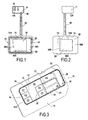
- FIG. 1 a device according to the invention.
- This electronic device is designated by the general reference 10.
- the device 10 comprises a microcircuit card 11.
- the microcircuit card 11 is an identification card to a mobile telephone network and has a format substantially corresponding to the ID-000 format, also designated by micro format. -SIM or SIM plug-in defined by ISO 7816. Alternatively, other card formats may be suitable.
- This card 11 is particularly intended to be incorporated in a compartment 100 of a body 102 of a mobile terminal 104 such as that shown in section on the figure 11 . More specifically, the card 11 is an identification card to a mobile phone network of SIM, USIM, RUIM type.
- the card body 12 defines the outer dimensions of the card 11 which are in this example in the ID-000 format.
- the card body 12 has a general shape of plate 0.76 mm thick and 2.5 mm wide and 2.5 mm long. This card body 12 also delimits opposite faces designated hereafter by the references 12A and 12B.
- This card 11 includes a body 12 of rigid card comprising a microcircuit 16 and a first external electrical contact 18 electrically connected to a supply terminal 20 of the microcircuit 16.
- the outer electrical contact 18 is in particular adapted to be connected to a battery 106 of the mobile terminal 104 (as shown in FIG. figure 11 ).
- This microcircuit 16 comprises communication means with a contact card reading device (not shown).
- the microcircuit 16 is incorporated in a module 14.
- This microcircuit module 14 is shown in detail on the figure 3 .
- the card body 12 is provided with a cavity and the module 14 is housed in the cavity.
- the card 11 preferably comprises an interface 13 of external contacts flush with the surface of the card 11.
- the module 14 comprises an electrically insulating support 30 delimiting opposite internal 301 and external 30E faces.
- the support 30 is for example made of fiberglass epoxy type, polyester or paper and has a thickness for example between 0.1 mm and 0.2 mm.
- the microcircuit 16 is preferably carried by the inner face 301 of the support 30 as shown in FIG. figure 2 .
- the interface 13 is carried by the outer face 30E of the support 30 of the module 14. As can be seen in particular on the figure 3 , the physical interface 13 extends over a surface much smaller than the total surface of the card 10.
- the interface 13 is preferably made of a layer of metallic material such as copper but may also be made, alternatively, by screen printing conductive ink type epoxy charged with silver or gold particles or by screen printing an electrically conductive polymer.
- the module 14 comprises a first series 22 of contacts comprising the first contact 18, this first series 22 being arranged to be electrically coupled with equipment external to the module 14.
- the external equipment is the mobile terminal 104 such as that shown in section on the figure 11 .
- a mobile terminal 104 comprises in particular a read head (not visible in the figure) comprising metal contact tabs arranged to be coupled with the contacts of the first series 22.
- the contacts of the first series 22 are in accordance with the ISO 7816 standard and their arrangement on the card body 12 is defined by the ISO 7816-2 standard.
- the contacts thus form metal correspond to the contacts C1, C2, C3, C5, C6, C7 of the ISO 7816 standard.
- the first external contact 18 is the contact C1.
- the location of the electrical contacts of the first series 22 on the body of the card 14 is defined in particular by the ISO 7816-2 standard.
- the ISO 7816-2 standard defines the number, the function and the position of the electrical surface contacts of the card 11 with an auxiliary interface such as the reading head of the mobile terminal 104.
- the contacts are referenced C1 to C8 in this standard.
- Contacts C4 and C8 have no function assigned by this standard.
- the first contact 18, that is to say, corresponding to the contact C1 is used for the supply of the microcircuit 16.
- the main battery 106 of the mobile terminal 104 is electrically coupled with the first contact 18 via the read head of the terminal 104.
- the module 14 also comprises a second electrical contact 24, distinct from the first contact 18, electrically connected to the power supply terminal 20 of the microcircuit 16.
- the device 10 also comprises an auxiliary battery 28 electrically connected to the second contact 24.
- the second contact 24 is an external contact to the card 11 so that it is directly accessible outside the card 11.
- This battery 28 comprises in particular a positive terminal intended to be electrically coupled with the second contact 24.
- the module 14 comprises a second series 26 of contacts comprising the second electrical contact 24.
- the interface 13 thus comprises in this case the first 22 and second 26 sets of contacts.
- first 22 and second 26 sets of contacts are carried respectively by first Z1 and second Z2 zones of the interface 13.
- At least one contact is common to both series 22 and 26 and is formed by a contact pad which extends on both the first Z1 and second Z2 areas.
- the common contact is the contact C5 defined by the ISO 7816 standard of the first series of contacts 22.
- This contact C5 also referred to as "GND”
- GND provides a common electrical ground to the microcircuit 16 and external equipment connected to the card 10 such as the main battery 106 and the auxiliary battery 28.
- the second series 24 comprises two external contacts, the contact C5 and the contact 24.
- the first series 22 shown in dashed lines in this figure, is connected to the microcircuit 16 via electrically conductive tracks 32 extending on the inner face 301 and electrically conductive son 34 connecting the terminals of the microcircuit 16 to These tracks 32 are electrically connected with the contacts of the first series 22 by the electrically conductive wires 34, such as gold wires, passing through vias 36 formed in the support 30.
- the second series of contacts 26 is also connected to the microcircuit 16 in a similar way.
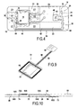
- the card 11 incorporates a conductive member 38, represented in strong lines on the figure 4 . More specifically, the first 18 and second 24 contacts are connected to the supply terminal 20 of the microcircuit 16 via this member 38.
- this member 38 is provided with first 42 and second 44 conductive branches comprising a common end 46 electrically connected to the supply terminal 20 of the microcircuit by a common branch 48 and first 50 and second 52 ends opposite to the end common 46, respectively connected to the first 18 and second 24 contacts.
- the first branch 42 is provided with a first switch 40 capable of adopting a first state of electrical connection of the first contact 18 to the terminal 20 and a second state of electrical insulation of the first contact 18 to the terminal 20.
- the switch 40 is formed by a diode 43.
- This diode 43 is arranged on the first branch 42 so that it allows the flow of a current in a direction from the first contact 18 to the second contact 24 and it prohibits the flow of current in an opposite direction.
- the auxiliary battery 28 when the main battery 106 is discharged, thanks to the conductive member 38, the auxiliary battery 28 does not discharge into the main battery 106. Indeed, the diode 43 prevents the flow of current in this direction. In addition, when the main battery 106 is charged, it recharges the auxiliary battery 28 since the diode 43 allows the flow of current in a direction from the main battery 106 to the auxiliary battery 28.
- the switch 40 is controlled by control means 41 formed for example by a portion of the microcircuit 16 so that the switch 40 changes state when crossing down or up one or more predefined thresholds.
- the first branch 42 is also provided with means 47 for measuring an intensity of the current passing through it, such as for example a shunt, and when this intensity exceeds a first predetermined intensity threshold, the switch 40 switches in a closed state to allow the supply of the microcircuit 16 and when the intensity falls below a second predefined intensity threshold (which may be less than or equal to the first threshold) the switch 40 switches to an open state so to prevent the flow of current in the direction from the auxiliary battery 28 to the main battery 106 which would result in the discharge of the latter.
- a second predefined intensity threshold which may be less than or equal to the first threshold
- the second branch 44 may also be provided with a switch 40 without the first leg 42 being provided with a switch.
- the switch 40 can also be controlled by means formed for example by a portion of the microcircuit 16 according to a predefined parameter.
- This predefined parameter is, for example, the activation of an application requiring an additional supply of the microcircuit 16 exceeding that delivered conventionally by the main battery 106 alone.
- the auxiliary battery 28 temporarily makes it possible to supply an additional supply of the microcircuit 16 for the operation of the microcircuit.
- the two branches 42 and 44 are each respectively provided with first 40A and second 40B switches.
- the microcircuit 16 may in this case comprise means for controlling the closing or opening of these two switches according to predefined parameters, such as the crossing upward and / or downward of one or more thresholds predefined by the intensity of the current passing through one or other of the branches of the organ, the activation of one or more specific applications requiring simultaneous power supply of the two batteries, etc.
- the support 30 carries on its inner face 30E the first external contact 18 and on its inner face 301 the microcircuit 16 and the conductive member 38.
- the conductive member 38 forms a printed circuit on the inner face 301 of the support.
- the branches of this member 38 form printed tracks on the support 30.
- the second contact 24 is an external contact which allows the connection of an additional external battery 28 to the module 14.
- the battery 28 is connected to the card body 12 by a flexible member 54 extending at least partially outside the card body 12 ( figure 1 ). This organ 54 is shown in detail on the figure 9 .
- the flexible member 54 comprises a first end portion 56 arranged to extend on the face 12A of the card body 12 carrying the interface 13 of external contacts.
- This end portion 56 forms in this case the electrical connector of the battery 28 with at least one of the two contacts C5 and 24 of the second series 26 of contacts.
- the flexible member 54 comprises a second end portion 58 forming a support of the battery 28.
- the first 56 and second 58 end portions are opposite to each other and are connected by a middle portion 60 of thinned section.
- the first end portion 56 forming a connector is electrically connected to the battery 28 by at least one electrically conductive element 62 arranged to extend longitudinally in the middle portion 60.
- This element is for example a wire.
- the battery 28 is generally plate-shaped and has a thickness of less than or equal to 150 microns.
- the battery 28 comprises a body 64 defining first and second opposite faces 64A, 64B and a peripheral side wall 66.
- Each face 64A, 64B of the battery 28 is provided with at least one extension 68A, 68B forming an electrical contact tab protruding from the body, the tongues 68A, 68B being arranged in offset position with respect to each other along the wall device 66 of the body 64 of the battery 28.
- the end portion 58 of the body flexible 54 comprises an orifice 70 arranged to receive the battery 28 so that the tabs 68 of the battery 28 each extend on one of the opposite faces of the end portion 58.
- tracks 72 and 73 electrically conductive are printed on the faces 58A, 58B of the end portion 58.
- the track 73 carried by the face 58B of the portion 58, allows the electrical connection of the negative terminal of the battery 28 corresponding to the tongue 68B contact C5.
- the track 73 is extended in the middle portion 60 by an electrically conductive wire to the contact C5 of the second series 26.
- the track 72 comprises a portion 72A carried by the face 58A and a portion 72B carried by the face 58B.
- the two parts 72A, 72B are electrically connected by an electrically conductive wire through a via 74 formed in the end portion 58 (as shown in dashed line on the figure 10 ).
- This track 72 is also extended by an electrically conductive wire to the contact 24 of the second series 26 for the connection of the positive terminal of the battery 28 corresponding to the tab 68A to the contact 24.
- the battery 28 is formed by a battery of battery cells such as anode element, a cathode element, an electrolyte element, anode and cathode current collection elements. These anode and cathode current collection elements thus form electrical terminals and are formed in this embodiment by the opposite faces of the battery 28.
- the first end portion 56 forming a connector carries at least one contact pad (not visible in the figures) arranged to extend facing at least one contact of the second set 26.
- the first part 56 carries two contact pads so as to connect each of the positive and negative terminals of the battery 28 with respectively the contacts 24 and C5 of the second series 26.
- the first end portion 56 is arranged to extend on the face 12A of the card body 12 carrying the contact interface 13 external leaving the contact pads (partially) of the first series 22 for their electrical coupling with the external equipment.
- the first end portion 56 comprises recesses 76 adapted to coincide, once the flexible member 54 attached to the card 10, with the contacts of the first series 22 corresponding to the contacts C1, C2, C3 , C5, C6, C7.
- the interface 13 further comprises a third series 77 of contacts 78 arranged to be electrically coupled to a near-field communication antenna 80.
- the first end portion 56 forms an electrical connector of the antenna 80 with at least one contact 78 of the third series 77.
- the first end portion 56 forming a support carries the antenna 80, the latter being arranged to extend around the battery 28 along the periphery of the second portion 58 forming a support.
- the card 11 is inserted in the compartment provided for this purpose of a mobile terminal 104.
- the face of the card carrying the contact interface is directed towards the bottom of the compartment 100 so that the contact pads of the first series are vis-à-vis with those of a read head of the mobile terminal.
- the end portion of the flexible member 54 carrying the support is then deported above the main battery 106. Indeed, the length of the middle portion is chosen to allow this delocalization.
- the end portion 58 forming a battery holder having substantially a constant thickness and equal to that of the battery is easily inserted between the battery compartment cover of the terminal and the main battery.
- the incorporation of such a battery does not require adaptation of existing mobile terminals and the battery can be inserted into any mobile terminal. This makes it possible to implement in any mobile terminal the "mobile payment" service.
Abstract
Description
La présente invention concerne le domaine technique des cartes à microcircuit et plus précisément mais non spécifiquement le domaine technique des cartes d'identification à un réseau de téléphonie mobile.The present invention relates to the technical field of microcircuit cards and more specifically but not specifically the technical field of identification cards to a mobile phone network.
Une carte d'identification est connue également sous le nom de carte SIM (acronyme anglais pour « Subscriber Identity Card Module ») ou carte USIM (pour « Universal Subscriber Identity Module » encore appelée carte UICC pour « UMTS Integrated Circuit Card ») ou encore carte RUIM (pour « Removable Universal Identity Module »).An identification card is also known as the SIM card (acronym for "Subscriber Identity Card Module") or USIM card (for "Universal Subscriber Identity Module" also called UICC card for "UMTS Integrated Circuit Card") or RUIM card (for "Removable Universal Identity Module").
Ces cartes comprennent généralement des moyens de traitement de données et des moyens de mémorisation de données pour le stockage des informations spécifiques à un utilisateur du réseau de téléphonie mobile.These cards generally comprise data processing means and data storage means for storing information specific to a user of the mobile telephone network.
La présence de cette carte au sein d'un terminal mobile (tel qu'un téléphone portable) permet à ce terminal (grâce aux informations contenues dans la carte d'identification) de se connecter au réseau et d'échanger des données avec d'autres dispositifs du réseau. Cette carte forme un élément sécurisé du téléphone permettant une authentification de l'utilisateur de cette carte grâce à une clef d'authentification mémorisée par exemple dans les moyens de mémorisation de la carte.The presence of this card within a mobile terminal (such as a mobile phone) allows this terminal (thanks to the information contained in the identification card) to connect to the network and to exchange data with data. other network devices. This card forms a secure element of the phone for authentication of the user of this card with an authentication key stored for example in the memory means of the card.
Il est connu dans l'état de la technique d'intégrer dans des terminaux mobiles d'autres applications en plus de l'application de téléphonie mobile telles que des applications de porte-monnaie électronique, de titres de transports (train, métro, bus, avion) sous forme de carte à microcircuit sans contact, etc.It is known in the state of the art to integrate in mobile terminals other applications in addition to the mobile application such as electronic wallet applications, tickets (train, metro, bus , airplane) in the form of a contactless microcircuit card, etc.
Par exemple, le paiement par terminal mobile, désigné couramment par l'expression « mobile paiement », consiste à payer un produit (ou service) par l'intermédiaire de son terminal mobile. De façon classique, le paiement est effectué par communication sans contact grâce à la présence d'une antenne de communication à champ proche incorporée dans le terminal qui permet l'échange de données entre le terminal et un équipement externe tel qu'une borne de paiement. Ainsi, pour utiliser ce type de services ou pour échanger des informations, l'utilisateur approche son terminal mobile de la borne, de manière à ce qu'une transaction par communication en champ proche puisse être effectuée.For example, payment by mobile terminal, commonly referred to as "mobile payment", consists of paying for a product (or service) via its mobile terminal. Conventionally, the payment is made by contactless communication thanks to the presence of a near-field communication antenna incorporated in the terminal which allows the exchange of data between the terminal and an external equipment such as a device. payment terminal. Thus, to use this type of service or to exchange information, the user approaches his mobile terminal from the terminal, so that a near field communication transaction can be performed.
Au cours de la transaction, le microcircuit de la carte d'identification effectue des échanges de données sécurisées permettant d'assurer la sécurité de la communication.During the transaction, the microcircuit of the identification card performs secure data exchanges to ensure the security of the communication.
A cet effet, la carte d'identification est munie d'une série de contacts externes, un des contacts étant apte à être couplé électriquement à la batterie principale du terminal mobile, qui alimente également les différents organes électriques du terminal, tels que l'écran, le clavier, etc. Par exemple, la série de contacts est conforme à la norme ISO 7816 des cartes à microcircuits et le contact externe est le contact C1 défini par cette norme.For this purpose, the identification card is provided with a series of external contacts, one of the contacts being able to be electrically coupled to the main battery of the mobile terminal, which also supplies the various electrical components of the terminal, such as the screen, keyboard, etc. For example, the series of contacts complies with the ISO 7816 standard for microcircuit cards and the external contact is the C1 contact defined by this standard.
Toutefois, lorsque la batterie principale est déchargée ou le terminal mobile éteint, le microcircuit n'est plus alimenté et ne peut effectuer aucune transaction ce qui présente un inconvénient certain pour l'utilisateur du terminal.However, when the main battery is discharged or the mobile terminal off, the microcircuit is no longer powered and can not perform any transaction which has a certain disadvantage for the user of the terminal.
Un but de la présente invention est de proposer une solution permettant le fonctionnement des applications liées à la carte SIM indépendamment de l'état de fonctionnement du terminal mobile.An object of the present invention is to provide a solution for the operation of applications related to the SIM card regardless of the operating state of the mobile terminal.
A cet effet, l'invention a pour objet un dispositif électronique comprenant une carte à microcircuit d'identification à un réseau de téléphonie mobile, comprenant un microcircuit muni d'une borne d'alimentation et un premier contact électrique externe apte à être couplé électriquement à une batterie principale et raccordé électriquement au microcircuit, caractérisé en ce que le dispositif comprend une batterie auxiliaire et en ce que la carte comprend :
- un deuxième contact électrique, distinct du premier contact, raccordé électriquement à la borne d'alimentation du microcircuit et à la batterie auxiliaire,
- un organe électriquement conducteur de raccordement des premier et deuxième contacts à cette borne.
- a second electrical contact, distinct from the first contact, electrically connected to the power supply terminal of the microcircuit and to the auxiliary battery,
- an electrically conductive member for connecting the first and second contacts to this terminal.
On entend au sens de l'invention par « contact électrique externe », un contact électrique affleurant à la surface de la carte.For the purposes of the invention, the term "external electrical contact" means an electrical contact flush with the surface of the card.
Les deux contacts électriques sont raccordés tous les deux à la borne d'alimentation du microcircuit. Ainsi, ces deux contacts sont destinés à être couplés à la batterie principale du terminal mobile et à une batterie auxiliaire qui est raccordée au deuxième contact. Cette batterie auxiliaire permet d'alimenter la carte d'identification, par exemple de type SIM, de manière indépendante du terminal mobile. Dans ce cas, lorsque la batterie principale est déchargée, la batterie auxiliaire permet d'alimenter le microcircuit de la carte SIM de manière à ce que les applications, telles que l'application « mobile paiement » puissent fonctionner.Both electrical contacts are connected to the power supply terminal of the microcircuit. Thus, these two contacts are intended to be coupled to the main battery of the mobile terminal and to an auxiliary battery which is connected to the second contact. This auxiliary battery makes it possible to feed the identification card, for example of the SIM type, independently of the mobile terminal. In this case, when the main battery is discharged, the auxiliary battery can power the microcircuit of the SIM card so that applications, such as the "mobile payment" application can operate.
De préférence, l'organe conducteur comprenant des première et deuxième branches conductrices comprenant une extrémité commune raccordée électriquement à la borne d'alimentation et des première et deuxième extrémités opposées à l'extrémité commune, raccordées respectivement aux premier et deuxième contacts, la première branche est munie d'un premier interrupteur susceptible d'adopter un premier état de raccordement électrique du premier contact à la borne et un deuxième état de séparation du premier contact et de la borne.Preferably, the conductive member comprising first and second conductive branches comprising a common end electrically connected to the supply terminal and first and second ends opposite to the common end, respectively connected to the first and second contacts, the first branch is provided with a first switch capable of adopting a first state of electrical connection of the first contact to the terminal and a second state of separation of the first contact and the terminal.
Dans un mode de réalisation de l'invention, le premier interrupteur comprend une diode agencée sur la première branche afin d'autoriser la circulation d'un courant dans un sens allant du premier contact vers le deuxième contact et d'interdire la circulation du courant dans un sens opposé.In one embodiment of the invention, the first switch comprises a diode arranged on the first branch to allow the flow of a current in a direction from the first contact to the second contact and to prohibit the flow of current in an opposite direction.
Ainsi, grâce à la diode, lorsque la batterie principale est déchargée, la batterie auxiliaire ne se décharge pas dans la batterie principale puisque le courant ne peut pas circuler de la batterie auxiliaire vers la batterie principale. En outre, lorsque la batterie principale est chargée, elle alimente le microcircuit tout en rechargeant la batterie auxiliaire si cette dernière est déchargée.Thus, thanks to the diode, when the main battery is discharged, the auxiliary battery does not discharge into the main battery since the current can not flow from the auxiliary battery to the main battery. In addition, when the main battery is charged, it feeds the microcircuit while recharging the auxiliary battery if the latter is discharged.
De préférence, le microcircuit comprend des moyens de commande du premier interrupteur en fonction d'un paramètre prédéfini. Dans un mode de réalisation, la première branche portant des moyens de mesure d'une intensité du courant la traversant, le paramètre est défini comme étant le franchissement à la hausse et/ou à la baisse d'au moins un seuil prédéfini d'intensité par l'intensité du courant mesurée. Il est possible ainsi d'avoir deux seuils distincts à la hausse et à la baisse de l'intensité du courant mesurée.Preferably, the microcircuit comprises means for controlling the first switch according to a predefined parameter. In one embodiment, the first branch carrying means for measuring an intensity of the current passing through it, the parameter is defined as the crossing. increasing and / or decreasing at least a predefined intensity threshold by the intensity of the measured current. It is thus possible to have two distinct thresholds for increasing and decreasing the intensity of the measured current.
De préférence, l'organe conducteur forme un circuit imprimé sur l'une des faces du support. Ainsi, l'organe est relativement peu encombrant et facile à réaliser.Preferably, the conductive member forms a printed circuit on one of the faces of the support. Thus, the organ is relatively compact and easy to perform.
Dans un mode de réalisation de l'invention, la carte comprend un module comprend un support portant sur l'une de ses faces le premier contact externe et, sur l'autre de ses faces, le microcircuit et l'organe conducteur.In one embodiment of the invention, the card comprises a module comprising a support bearing on one of its faces the first external contact and, on the other of its faces, the microcircuit and the conductive member.
Un dispositif selon l'invention peut en outre comprendre l'une ou plusieurs des caractéristiques selon lesquelles :
- la deuxième branche est munie d'un deuxième interrupteur susceptible d'adopter un premier état de raccordement de la batterie auxiliaire à la borne d'alimentation et un deuxième état de séparation de la batterie auxiliaire et de cette borne ;
- le deuxième contact est un contact externe et la batterie auxiliaire est externe à la carte ;
- la carte comprend une interface de contacts externes agencée affleurant à la surface de la carte et comprenant les premier et deuxième contacts ;
- l'interface comprend une première série de contacts externes, par exemple conforme à la norme ISO-7816, comprenant le premier contact et une deuxième série de contacts externes comprenant le deuxième contact, les première et deuxième séries étant respectivement agencées pour être couplées respectivement à des premier et deuxième équipements externes au microcircuit ;
- les première et deuxième séries de contacts sont portées respectivement par des première et deuxième zones de l'interface ;
- au moins un contact est commun aux deux séries, par exemple le contact C5 défini par la norme ISO 7816 et est formé par une plage de contact qui s'étend sur les première et deuxième zones ;
- le deuxième contact est un contact interne au module et la batterie auxiliaire est incorporée dans le corps de la carte.
- the second branch is provided with a second switch capable of adopting a first state of connection of the auxiliary battery to the power supply terminal and a second state of separation of the auxiliary battery and this terminal;
- the second contact is an external contact and the auxiliary battery is external to the card;
- the card comprises an interface of external contacts arranged flush with the surface of the card and comprising the first and second contacts;
- the interface comprises a first series of external contacts, for example in accordance with the ISO-7816 standard, comprising the first contact and a second series of external contacts comprising the second contact, the first and second series being respectively arranged to be coupled respectively to first and second equipment external to the microcircuit;
- the first and second series of contacts are carried respectively by first and second zones of the interface;
- at least one contact is common to both series, for example contact C5 defined by ISO 7816 and is formed by a contact pad which extends over the first and second zones;
- the second contact is an internal contact to the module and the auxiliary battery is incorporated in the body of the card.
L'invention a en outre pour objet un système électronique, tel qu'un terminal mobile, comprenant un logement pour une carte à microcircuit et une batterie principale d'alimentation du microcircuit, caractérisé en ce qu'il comprend un dispositif selon l'une quelconque des revendications précédentes, la batterie principale étant couplée électriquement avec le premier contact et la batterie auxiliaire étant couplée électriquement avec le second contact.The invention has further for an electronic object, such as a mobile terminal, comprising a seat for a microcircuit card and a main battery supplying the microcircuit, characterized in that it comprises a device according to any one of the preceding claims, the main battery being electrically coupled to the first contact and the auxiliary battery being electrically coupled to the second contact.
D'autres caractéristiques et avantages de l'invention apparaîtront à la lumière de la description qui suit, faite en référence aux dessins annexés dans lesquels :
- la
figure 1 est une vue de dessus d'un dispositif selon l'invention comprenant une carte à microcircuit et une batterie auxiliaire raccordée électriquement à la carte ; - la
figure 2 est une vue de dessous du dispositif de lafigure 1 ; - la
figure 3 est une vue en perspective de la carte à microcircuit du dispositif de lafigure 1 ; - la
figure 4 représente une vue de dessous d'un module incorporé dans la carte de lafigure 3 comprenant un organe conducteur de raccordement électrique de la batterie auxiliaire au microcircuit ; - la
figure 5 est un schéma électrique illustrant le raccordement électrique des contacts au microcircuit de lafigure 4 ; - les
figures 6 à 8 représentent des variantes de réalisation du schéma électrique de lafigure 5 ; - la
figure 9 représente un organe flexible de raccordement de la batterie auxiliaire et de la carte de lafigure 3 ; - la
figure 10 est une vue en coupe de l'organe flexible selon la ligne 10-10 de lafigure 1 ; - la
figure 11 est une vue en coupe d'un terminal mobile comprenant le dispositif de lafigure 1 .
- the
figure 1 is a top view of a device according to the invention comprising a microcircuit card and an auxiliary battery electrically connected to the card; - the
figure 2 is a bottom view of the device of thefigure 1 ; - the
figure 3 is a perspective view of the microcircuit card of the device of thefigure 1 ; - the
figure 4 represents a bottom view of a module embedded in the map of thefigure 3 comprising a conductive member for electrical connection of the auxiliary battery to the microcircuit; - the
figure 5 is an electrical diagram illustrating the electrical connection of the contacts to the microcircuit of thefigure 4 ; - the
Figures 6 to 8 represent alternative embodiments of the circuit diagram of thefigure 5 ; - the
figure 9 represents a flexible connecting member of the auxiliary battery and the card of thefigure 3 ; - the
figure 10 is a sectional view of the flexible member along the line 10-10 of thefigure 1 ; - the
figure 11 is a sectional view of a mobile terminal comprising the device of thefigure 1 .
On a représenté sur la
Le dispositif 10 comprend une carte à microcircuit 11. Dans ce mode de réalisation, la carte à microcircuit 11 est une carte d'identification à un réseau de téléphonie mobile et a un format correspondant sensiblement au format ID-000, désigné également par format micro-SIM ou Plug-in SIM défini par la norme ISO 7816. En variante, d'autres formats de carte peuvent convenir.The
Cette carte 11 est notamment destiné à être incorporée dans un compartiment 100 d'un corps 102 d'un terminal mobile 104 tel que celui représenté en coupe sur la
Par exemple, le corps de carte 12 délimite les dimensions extérieures de la carte 11 qui sont dans cet exemple conforme au format ID-000. Ainsi, le corps de carte 12 a une forme générale de plaque d'épaisseur 0.76 mm et de largeur 2.5 mm et de longueur 2.5 mm. Ce corps de carte 12 délimite également des faces opposées désignées par la suite par les références 12A et 12B.For example, the
En référence à la
De préférence, le microcircuit 16 est incorporé dans un module 14. Ce module à microcircuit 14 est représenté en détail sur la
La carte 11 comprend de préférence une interface 13 de contacts externes affleurant à la surface de la carte 11.The
Dans cet exemple, le module 14 comprend un support 30 électriquement isolant délimitant des faces opposées interne 301 et externe 30E. Le support 30 est par exemple réalisé en fibre de verre de type époxy, en polyester ou bien en papier et a une épaisseur comprise par exemple entre 0.1 mm et 0.2 mm. Le microcircuit 16 est porté de préférence par la face interne 301 du support 30 comme cela est représenté sur la
L'interface 13 est de préférence réalisée dans une couche de matériau métallique telle que du cuivre mais peut également être réalisée, en variante, par sérigraphie d'encre conductrice de type encre époxy chargée de particules d'argent ou d'or ou par sérigraphie d'un polymère électriquement conducteur.The
De préférence, le module 14 comprend une première série 22 de contacts comprenant le premier contact 18, cette première série 22 étant agencée pour être couplée électriquement avec un équipement externe au module 14.Preferably, the
Ainsi, dans ce mode de réalisation, l'équipement externe est le terminal mobile 104 tel que celui représenté en coupe sur la
Par exemple, les contacts de la première série 22 sont conformes à la norme ISO 7816 et leur disposition sur le corps de carte 12 est définie par la norme ISO 7816-2. Les contacts forment ainsi des plages métalliques qui correspondent aux contacts C1, C2, C3, C5, C6, C7 de la norme ISO 7816. Dans cet exemple, le premier contact externe 18 est le contact C1. L'emplacement des contacts électriques de la première série 22 sur le corps de la carte 14 est notamment défini par la norme ISO 7816-2.For example, the contacts of the
En effet, la norme ISO 7816-2 définit le nombre, la fonction et la position des contacts électriques de surface de la carte 11 avec une interface annexe telle que la tête de lecture du terminal mobile 104. Classiquement, les contacts sont référencés C1 à C8 dans cette norme. Les contacts C4 et C8 n'ont pas de fonction attribuée par cette norme.Indeed, the ISO 7816-2 standard defines the number, the function and the position of the electrical surface contacts of the
En particulier, le premier contact 18, c'est-à-dire correspondant au contact C1, est utilisé pour l'alimentation du microcircuit 16. Ainsi, dans ce mode de réalisation, la batterie principale 106 du terminal mobile 104 est couplée électriquement avec le premier contact 18 par l'intermédiaire de la tête de lecture du terminal 104.In particular, the
Le module 14 comprend également un deuxième contact électrique 24, distinct du premier contact 18, raccordé électriquement à la borne d'alimentation 20 du microcircuit 16.The
En particulier, le dispositif 10 comprend encore une batterie auxiliaire 28 raccordée électriquement au deuxième contact 24.In particular, the
Dans ce mode de réalisation, le deuxième contact 24 est un contact externe à la carte 11 de manière à ce qu'il soit directement accessible en-dehors de la carte 11. Cette batterie 28 comprend notamment une borne positive destinée à être couplée électriquement avec le deuxième contact 24.In this embodiment, the
De préférence, le module 14 comprend une deuxième série 26 de contacts comprenant le deuxième contact électrique 24.Preferably, the
L'interface 13 comprend ainsi dans ce cas les première 22 et deuxième 26 séries de contacts.The
Dans cet exemple, les première 22 et deuxième 26 séries de contacts sont portées respectivement par des première Z1 et deuxième Z2 zones de l'interface 13.In this example, the first 22 and second 26 sets of contacts are carried respectively by first Z1 and second Z2 zones of the
En outre, comme cela est visible sur la
Comme cela est illustré en détail sur la
Afin de gérer l'alimentation du microcircuit 16 par la batterie principale 106 et par la batterie auxiliaire 28, la carte 11 incorpore un organe conducteur 38, représenté en trait fort sur la
De préférence, cet organe 38 est muni de première 42 et deuxième 44 branches conductrices comprenant une extrémité commune 46 raccordée électriquement à la borne d'alimentation 20 du microcircuit par une branche commune 48 et des première 50 et deuxième 52 extrémités opposées à l'extrémité commune 46, raccordées respectivement aux premier 18 et deuxième 24 contacts.Preferably, this
En outre, la première branche 42 est munie d'un premier interrupteur 40 susceptible d'adopter un premier état de raccordement électrique du premier contact 18 à la borne 20 et un deuxième état d'isolation électrique du premier contact 18 à la borne 20.In addition, the
Dans le mode de réalisation illustré sur la
On a représenté sur la
Ainsi, lorsque la batterie principale 106 est déchargée, grâce à l'organe conducteur 38, la batterie auxiliaire 28 ne se décharge pas dans la batterie principale 106. En effet, la diode 43 empêche la circulation du courant dans ce sens. En outre, lorsque la batterie principale 106 est chargée, elle recharge la batterie auxiliaire 28 puisque la diode 43 autorise la circulation du courant dans un sens allant de la batterie principale 106 à la batterie auxiliaire 28.Thus, when the
Dans une première variante illustrée sur la
A cet effet, la première branche 42 est également munie de moyens 47 de mesure d'une intensité du courant la traversant tels que par exemple un shunt et lorsque cette intensité dépasse un premier seuil d'intensité prédéfini, l'interrupteur 40 bascule dans un état fermé pour permettre l'alimentation du microcircuit 16 et lorsque l'intensité descend en-dessous d'un deuxième seuil d'intensité prédéfini (qui peut être inférieur ou égale au premier seuil) l'interrupteur 40 bascule dans un état ouvert de manière à empêcher la circulation du courant dans le sens allant de la batterie auxiliaire 28 vers la batterie principale 106 ce qui aurait pour conséquence d'entraîner la décharge de cette dernière.For this purpose, the
Dans une deuxième variante illustrée par la
Enfin, dans une troisième variante illustrée par la
De préférence, comme cela est représenté sur la
En outre, de préférence, l'organe conducteur 38 forme un circuit imprimé sur la face interne 301 du support. Ainsi, les branches de cet organe 38 forment des pistes imprimées sur le support 30.In addition, preferably, the
Dans ce mode de réalisation, le deuxième contact 24 est un contact externe ce qui permet le raccordement d'une batterie additionnelle 28 externe au module 14. Ainsi, dans ce mode de réalisation, la batterie 28 est reliée au corps de carte 12 par un organe flexible 54 s'étendant au moins partiellement en-dehors du corps de carte 12 (
Comme cela est représenté sur la
En outre, l'organe flexible 54 comprend une deuxième partie d'extrémité 58 formant support de la batterie 28. Dans l'exemple décrit, les première 56 et deuxième 58 parties d'extrémités sont opposées entre elles et sont reliées par une partie médiane 60 de section amincie.In addition, the
La première partie d'extrémité 56 formant connecteur est raccordée électriquement à la batterie 28 par au moins un élément 62 électriquement conducteur agencé pour s'étendre longitudinalement dans la partie médiane 60 Cet élément est par exemple un fil métallique.The
Dans cet exemple, la batterie 28 est en forme générale de plaque et a une épaisseur inférieure ou égale à 150 microns. On a représenté sur la
Dans ce mode de réalisation, la batterie 28 comprend un corps 64 délimitant des première et deuxième faces opposées 64A, 64B et une paroi latérale périphérique 66.In this embodiment, the
Chaque face 64A, 64B de la batterie 28 est pourvue d'au moins un prolongement 68A, 68B formant une languette de contact électrique, dépassant du corps, les languettes 68A, 68B étant agencées en position décalée les unes par rapport aux autres suivant la paroi périphérique 66 du corps 64 de la batterie 28.Each
Ces languettes 68 permettent le raccordement électrique de la batterie 28 à des composants électroniques externes à la batterie 28. Ces languettes 68 forment avantageusement des bornes électriques de la batterie 28. Dans ce mode de réalisation, la partie d'extrémité 58 de l'organe flexible 54 comprend un orifice 70 agencé pour recevoir la batterie 28 de manière à ce que les languettes 68 de la batterie 28 s'étendent chacune sur une des faces opposées de la partie d'extrémité 58.These tabs 68 allow the electrical connection of the
En outre, comme cela est visible sur les
En outre, la piste 72 comprend une partie 72A portée par la face 58A et une partie 72B portée par la face 58B. Les deux parties 72A, 72B sont raccordées électriquement par un fil électriquement conducteur traversant un via 74 ménagé dans la partie d'extrémité 58 (tel que représenté en pointillé sur la
De préférence, la batterie 28 est formée par une pile d'éléments de batterie tels qu'un élément d'anode, un élément de cathode, un élément d'électrolyte, des éléments de collecte de courants d'anode et de cathode. Ces éléments de collecte de courant d'anode et de cathode forment ainsi des bornes électriques et sont formés dans ce mode de réalisation par les faces opposées de la batterie 28.Preferably, the
La première partie d'extrémité 56 formant connecteur porte au moins une plage de contact (non visible sur les figures) agencée pour s'étendre en vis-à-vis d'au moins d'un contact de la deuxième série 26. Dans l'exemple décrit, la première partie 56 porte deux plages de contact de manière à connecter chacune des bornes positive et négative de la batterie 28 avec respectivement les contacts 24 et C5 de la deuxième série 26.The
De préférence, la première partie d'extrémité 56 est agencée pour s'étendre sur la face 12A du corps de carte 12 portant l'interface 13 de contacts externes en laissant nus les plages de contacts (de façon partielle) de la première série 22 pour leur couplage électrique avec l'équipement externe.Preferably, the
Dans ce mode de réalisation, la première partie d'extrémité 56 comprend des évidements 76 aptes à coïncider, une fois l'organe flexible 54 rapporté sur la carte 10, avec les contacts de la première série 22 correspondant aux contacts C1, C2, C3, C5, C6, C7.In this embodiment, the
Dans le mode de réalisation illustré sur les figures, l'interface 13 comprend en outre une troisième série 77 de contacts 78 agencée pour être couplée électriquement à une antenne de communication 80 à champ proche. Dans ce cas, la première partie d'extrémité 56 forme connecteur électrique de l'antenne 80 avec au moins un contact 78 de la troisième série 77.In the embodiment illustrated in the figures, the
En outre, de préférence, la première partie d'extrémité 56 formant support porte l'antenne 80, cette dernière étant agencée pour s'étendre autour de la batterie 28 le long de la périphérie de la deuxième partie 58 formant support.In addition, preferably, the
On va maintenant décrire en détail les principaux aspects du fonctionnement d'un dispositif électronique selon l'invention.The main aspects of the operation of an electronic device according to the invention will now be described in detail.
Conformément à la
La partie d'extrémité de l'organe flexible 54 portant le support est alors déportée au-dessus de la batterie principale 106. En effet, la longueur de la partie médiane est choisie de manière à autoriser cette délocalisation.The end portion of the
La partie d'extrémité 58 formant support de batterie ayant sensiblement une épaisseur constante et égale à celle de la batterie est facilement insérable entre le couvercle du compartiment batterie du terminal et la batterie principale. Ainsi, l'incorporation d'une telle batterie ne nécessite pas d'adaptation de terminaux mobiles existants et la batterie peut être insérée dans un terminal mobile quelconque. Ceci permet d'implémenter dans n'importe quel terminal mobile le service « mobile paiement».The
Il est bien entendu que les modes de réalisation qui viennent d'être décrits ne présentent aucun caractère limitatif et qu'ils pourront recevoir toute modification désirable sans sortir pour cela du cadre de l'invention qui est défini par les revendications attachées à la demande.It is understood that the embodiments just described are not limiting and they can receive any desirable modification without departing from the scope of the invention which is defined by the claims attached to the application.
Claims (15)
Applications Claiming Priority (1)
| Application Number | Priority Date | Filing Date | Title |
|---|---|---|---|
| FR0952513A FR2944632B1 (en) | 2009-04-17 | 2009-04-17 | ELECTRONIC DEVICE COMPRISING A MICROCIRCUIT CARD AND AN AUXILIARY BATTERY. |
Publications (2)
| Publication Number | Publication Date |
|---|---|
| EP2242007A2 true EP2242007A2 (en) | 2010-10-20 |
| EP2242007A3 EP2242007A3 (en) | 2011-08-03 |
Family
ID=41124260
Family Applications (1)
| Application Number | Title | Priority Date | Filing Date |
|---|---|---|---|
| EP10159908A Withdrawn EP2242007A3 (en) | 2009-04-17 | 2010-04-14 | Electronic device including a chip card and an auxiliary battery |
Country Status (2)
| Country | Link |
|---|---|
| EP (1) | EP2242007A3 (en) |
| FR (1) | FR2944632B1 (en) |
Family Cites Families (4)
| Publication number | Priority date | Publication date | Assignee | Title |
|---|---|---|---|---|
| JPS63198567U (en) * | 1987-06-12 | 1988-12-21 | ||
| US5761061A (en) * | 1993-12-17 | 1998-06-02 | Berg Technology, Inc. | Data processing medium, its backup circuit, and data processing system |
| KR100965323B1 (en) * | 2003-09-08 | 2010-06-22 | 샤프 가부시키가이샤 | Electronic circuit, non-contact ic system and mobile terminal |
| KR101327483B1 (en) * | 2006-11-21 | 2013-11-08 | 삼성전자주식회사 | Subscirber identification module card and portable wireless terminal using the same |
-
2009
- 2009-04-17 FR FR0952513A patent/FR2944632B1/en active Active
-
2010
- 2010-04-14 EP EP10159908A patent/EP2242007A3/en not_active Withdrawn
Non-Patent Citations (1)
| Title |
|---|
| None |
Also Published As
| Publication number | Publication date |
|---|---|
| FR2944632B1 (en) | 2011-05-06 |
| EP2242007A3 (en) | 2011-08-03 |
| FR2944632A1 (en) | 2010-10-22 |
Similar Documents
| Publication | Publication Date | Title |
|---|---|---|
| EP1692642B1 (en) | Security document having a contactless chip with data masking | |
| EP2218040B1 (en) | Radiofrequency communication device including a timer | |
| WO2007051922A1 (en) | Contactless electronic microcircuit document and proximity sensor | |
| EP3432221A1 (en) | Electronic card comprising a fingerprint sensor and method of manufacturing such a card | |
| EP2194491A1 (en) | Electronic card with control means | |
| EP1695268A1 (en) | Identification booklet having a radio frequency identification device | |
| EP3223199B1 (en) | Method for manufacturing a multi-functional module and device including same | |
| EP1861813A1 (en) | Electronic module and chip card with indicator light | |
| EP1116179B1 (en) | Contactless card comprising inhibiting means | |
| EP0349412A1 (en) | Data carrier and control system of such a data carrier | |
| EP2780867A1 (en) | Radio-frequency communication device whereof the operation is controlled by a deliberate gesture by the wearer | |
| FR2901899A1 (en) | MASKING DEVICE FOR NON-CONTACT PORTABLE OBJECT OF SECURE DOCUMENT TYPE WITH RADIO FREQUENCY DEVICE | |
| WO2000067199A1 (en) | Method for making contactless cards by lamination and contactless card obtained by said method | |
| EP2182473A1 (en) | Electronic device authorising contactless near-field communications | |
| WO1989003325A1 (en) | Anti-theft system for a radio receiver used particularly in a motor vehicle | |
| EP2239691B1 (en) | Unit with USB key including a chip card | |
| WO2010060956A1 (en) | Electric/electronic circuit for connecting a device to a radiofrequency antenna | |
| EP3794507B1 (en) | Electronic passport secured against unauthorised reading | |
| EP2242007A2 (en) | Electronic device including a chip card and an auxiliary battery | |
| WO2012032066A1 (en) | Power supply case for a communication device | |
| EP0714076A1 (en) | Portable object with an electronic circuit powered by internal battery and with a data memory, method and device for externally powering this object and data transmission with the latter | |
| FR2944631A1 (en) | Electronic device for use in portable telephone, for e.g. product payment operation, has battery supplying power to microcircuit, where battery is connected to card body by flexible member partially extending outside card body | |
| WO2014060290A1 (en) | Method for producing a multi-component device comprising an electrical and/or electronic module | |
| EP0564012A1 (en) | Electronic Memory Card with memory available balance display | |
| FR2949589A1 (en) | ELECTRONIC DEVICE COMPRISING A MICROCIRCUIT CARD |
Legal Events
| Date | Code | Title | Description |
|---|---|---|---|
| PUAI | Public reference made under article 153(3) epc to a published international application that has entered the european phase |
Free format text: ORIGINAL CODE: 0009012 |
|
| 17P | Request for examination filed |
Effective date: 20100414 |
|
| AK | Designated contracting states |
Kind code of ref document: A2 Designated state(s): AT BE BG CH CY CZ DE DK EE ES FI FR GB GR HR HU IE IS IT LI LT LU LV MC MK MT NL NO PL PT RO SE SI SK SM TR |
|
| AX | Request for extension of the european patent |
Extension state: AL BA ME RS |
|
| PUAL | Search report despatched |
Free format text: ORIGINAL CODE: 0009013 |
|
| AK | Designated contracting states |
Kind code of ref document: A3 Designated state(s): AT BE BG CH CY CZ DE DK EE ES FI FR GB GR HR HU IE IS IT LI LT LU LV MC MK MT NL NO PL PT RO SE SI SK SM TR |
|
| AX | Request for extension of the european patent |
Extension state: AL BA ME RS |
|
| RIC1 | Information provided on ipc code assigned before grant |
Ipc: H04B 1/38 20060101ALI20110630BHEP Ipc: G06K 19/077 20060101AFI20110630BHEP |
|
| RIN1 | Information on inventor provided before grant (corrected) |
Inventor name: BOSQUET, OLIVIER Inventor name: STRANGES, LORENZO Inventor name: DANREE, ARNAUD Inventor name: DUMOULIN, JEROME |
|
| RIC1 | Information provided on ipc code assigned before grant |
Ipc: G06K 19/077 20060101AFI20131010BHEP Ipc: G06K 19/07 20060101ALI20131010BHEP Ipc: H04B 1/38 20060101ALI20131010BHEP |
|
| GRAP | Despatch of communication of intention to grant a patent |
Free format text: ORIGINAL CODE: EPIDOSNIGR1 |
|
| INTG | Intention to grant announced |
Effective date: 20131216 |
|
| STAA | Information on the status of an ep patent application or granted ep patent |
Free format text: STATUS: THE APPLICATION IS DEEMED TO BE WITHDRAWN |
|
| 18D | Application deemed to be withdrawn |
Effective date: 20140429 |