EP2241962A2 - Information processing apparatus, information processing method, and program - Google Patents
Information processing apparatus, information processing method, and program Download PDFInfo
- Publication number
- EP2241962A2 EP2241962A2 EP10002586A EP10002586A EP2241962A2 EP 2241962 A2 EP2241962 A2 EP 2241962A2 EP 10002586 A EP10002586 A EP 10002586A EP 10002586 A EP10002586 A EP 10002586A EP 2241962 A2 EP2241962 A2 EP 2241962A2
- Authority
- EP
- European Patent Office
- Prior art keywords
- touch
- touch panel
- touch operation
- detected
- end side
- Prior art date
- Legal status (The legal status is an assumption and is not a legal conclusion. Google has not performed a legal analysis and makes no representation as to the accuracy of the status listed.)
- Withdrawn
Links
Images


Classifications
-
- G—PHYSICS
- G06—COMPUTING; CALCULATING OR COUNTING
- G06F—ELECTRIC DIGITAL DATA PROCESSING
- G06F3/00—Input arrangements for transferring data to be processed into a form capable of being handled by the computer; Output arrangements for transferring data from processing unit to output unit, e.g. interface arrangements
- G06F3/01—Input arrangements or combined input and output arrangements for interaction between user and computer
- G06F3/03—Arrangements for converting the position or the displacement of a member into a coded form
- G06F3/041—Digitisers, e.g. for touch screens or touch pads, characterised by the transducing means
- G06F3/0416—Control or interface arrangements specially adapted for digitisers
-
- G—PHYSICS
- G06—COMPUTING; CALCULATING OR COUNTING
- G06F—ELECTRIC DIGITAL DATA PROCESSING
- G06F1/00—Details not covered by groups G06F3/00 - G06F13/00 and G06F21/00
- G06F1/16—Constructional details or arrangements
- G06F1/1613—Constructional details or arrangements for portable computers
- G06F1/1633—Constructional details or arrangements of portable computers not specific to the type of enclosures covered by groups G06F1/1615 - G06F1/1626
- G06F1/1637—Details related to the display arrangement, including those related to the mounting of the display in the housing
- G06F1/1641—Details related to the display arrangement, including those related to the mounting of the display in the housing the display being formed by a plurality of foldable display components
-
- G—PHYSICS
- G06—COMPUTING; CALCULATING OR COUNTING
- G06F—ELECTRIC DIGITAL DATA PROCESSING
- G06F1/00—Details not covered by groups G06F3/00 - G06F13/00 and G06F21/00
- G06F1/16—Constructional details or arrangements
- G06F1/1613—Constructional details or arrangements for portable computers
- G06F1/1633—Constructional details or arrangements of portable computers not specific to the type of enclosures covered by groups G06F1/1615 - G06F1/1626
- G06F1/1637—Details related to the display arrangement, including those related to the mounting of the display in the housing
- G06F1/1643—Details related to the display arrangement, including those related to the mounting of the display in the housing the display being associated to a digitizer, e.g. laptops that can be used as penpads
-
- G—PHYSICS
- G06—COMPUTING; CALCULATING OR COUNTING
- G06F—ELECTRIC DIGITAL DATA PROCESSING
- G06F1/00—Details not covered by groups G06F3/00 - G06F13/00 and G06F21/00
- G06F1/16—Constructional details or arrangements
- G06F1/1613—Constructional details or arrangements for portable computers
- G06F1/1633—Constructional details or arrangements of portable computers not specific to the type of enclosures covered by groups G06F1/1615 - G06F1/1626
- G06F1/1637—Details related to the display arrangement, including those related to the mounting of the display in the housing
- G06F1/1647—Details related to the display arrangement, including those related to the mounting of the display in the housing including at least an additional display
-
- G—PHYSICS
- G06—COMPUTING; CALCULATING OR COUNTING
- G06F—ELECTRIC DIGITAL DATA PROCESSING
- G06F3/00—Input arrangements for transferring data to be processed into a form capable of being handled by the computer; Output arrangements for transferring data from processing unit to output unit, e.g. interface arrangements
- G06F3/01—Input arrangements or combined input and output arrangements for interaction between user and computer
- G06F3/048—Interaction techniques based on graphical user interfaces [GUI]
- G06F3/0487—Interaction techniques based on graphical user interfaces [GUI] using specific features provided by the input device, e.g. functions controlled by the rotation of a mouse with dual sensing arrangements, or of the nature of the input device, e.g. tap gestures based on pressure sensed by a digitiser
- G06F3/0488—Interaction techniques based on graphical user interfaces [GUI] using specific features provided by the input device, e.g. functions controlled by the rotation of a mouse with dual sensing arrangements, or of the nature of the input device, e.g. tap gestures based on pressure sensed by a digitiser using a touch-screen or digitiser, e.g. input of commands through traced gestures
Definitions
- the present invention relates to an information processing apparatus including a plurality of touch panels, an information processing method for the information processing apparatus, and a program therefor.
- Patent Document 1 discloses a watch-type PDA (Personal Digital Assistant) in which a plurality of panels including LCDs (Liquid Crystal Displays) integrally formed with a plurality of touch panels are connected by a hinge portion.
- LCDs Liquid Crystal Displays
- an information processing apparatus including a first touch panel, a second touch panel, a touch sensor, and a controller.
- the first touch panel displays an object and detects a first touch operation of a user on the object.
- the second touch panel detects a second touch operation of the user.
- the touch sensor is provided between the first touch panel and the second touch panel and detects a third touch operation of the user.
- the controller moves the object displayed on the first touch panel in accordance with the first touch operation. Then, the controller displays the object on the second touch panel when the third touch operation is detected within a first time period since the first touch operation has become undetected and the second touch operation is detected within a second time period since the third touch operation is detected.
- the information processing apparatus can execute a drag-and-drop operation across the first touch panel and the second touch panel by recognizing the second touch operation detected within a predetermined time period since the end of the first touch operation as a series of touch operations. Moreover, since the touch sensor is provided, the information processing apparatus is also capable of positively detecting the drag-and-drop operation and preventing an unintentional operation from being made.
- the first and second touch panels include those that include a non-contact-type capacitance sensor, and the first and second touch operations include those that are not accompanied by a physical contact with respect to the first and second touch panels.
- the object includes an icon, a window, and various other images.
- the controller may display, near the touch sensor, when the third touch operation is detected, an image indicating that the object is to be moved to the second touch panel.
- the "image indicating that the object is to be moved” may indirectly indicate the movement by, when the second touch panel is seen as a water surface, for example, an animation such as a ripple or ruffle of the water surface.
- the image may directly indicate the movement with a part of an object, letters indicating the movement, and the like.
- the user can positively grasp that a drag operation of the object is to be executed across the two touch panels.
- the first touch panel may include a first touch surface having a first end side and a second end side opposed to the first end side.
- the second touch panel may include a second touch surface having a third end side adjacent to the second end side with the touch sensor interposed therebetween and a fourth end side opposed to the third end side.
- the controller may display, when the third touch operation is detected, the object such that a part of the object sticks out from the third end side of the second touch panel from the touch sensor side.
- the first touch panel may include a first touch surface to which the first touch operation is input
- the second touch panel may include a second touch surface to which the second touch operation is input
- the touch sensor may include a third touch surface to which the third touch operation is input.
- the first touch surface, the second touch surface, and the third touch surface may be provided so that the first touch surface, the second touch surface, and the third touch surface are positioned on the same plane at a time the first touch operation, the second touch operation, and the third touch operation are input.
- the user can intuitionally perform a drag-and-drop operation from the first touch panel to the second touch panel via the touch sensor without being conscious of the panels and the touch sensor.
- the controller may detect a time period from a time the first touch operation is detected to a time the second touch operation is detected. Further, the controller may display, when the time period is a predetermined value or less, the object on the second touch panel irrespective of whether the third touch operation has been detected.
- the information processing apparatus can move, when the drag operation has momentum, that is, when a movement velocity of a finger, a touch pen, and the like is high, the object to the second touch panel and display it thereon irrespective of whether the third touch operation has been detected. Therefore, even when the third touch operation is not detected although a drag-and-drop operation has been made, the information processing apparatus can positively execute the drag-and-drop operation.
- an information processing apparatus including a first touch panel, a second touch panel, and a controller.
- the first touch panel displays an object and detects a first touch operation of a user on the object.
- the second touch panel is provided adjacent to the first touch panel in a first direction and detects a second touch operation of the user.
- the controller moves the object displayed on the first touch panel in accordance with the first touch operation and stores a first detection coordinate in a second direction orthogonal to the first direction, that is obtained at a time the first touch operation has become undetected.
- the controller displays the object on the second touch panel when the second touch operation is detected within a predetermined time period since the first touch operation has become undetected and a second detection coordinate in the second direction obtained at the time the second touch operation is detected is within a predetermined range from the first detection coordinate.
- the information processing apparatus can move the object assuming that a drag-and-drop operation has been made from the first touch panel to the second touch panel. Therefore, the information processing apparatus can prevent the object from being moved unintentionally when merely the first touch operation and the second touch operation are detected successively.
- the first touch panel may include a first touch surface having a first end side and a second end side opposed to the first end side.
- the second touch panel may include a second touch surface having a third end side adjacent to the second end side and a fourth end side opposed to the third end side.
- the controller may display, when the second detection coordinate in the second direction is within the predetermined range from the first detection coordinate, the object such that a part of the object sticks out from the third end side of the second touch panel.
- an information processing method including displaying, by a first touch panel, an object and detecting a first touch operation of a user on the object, and detecting, by a second touch panel, a second touch operation of the user.
- the information processing method also includes detecting, by a touch sensor that is provided between the first touch panel and the second touch panel, a third touch operation of the user.
- the object displayed on the first touch panel is moved in accordance with the first touch operation, and the object is displayed on the second touch panel when the third touch operation is detected within a first time period since the first touch operation has become undetected and the second touch operation is detected within a second time period since the third touch operation is detected.
- the first touch operation to the first touch panel, the third touch operation to the touch sensor, and the second touch operation to the second touch panel can be recognized as a series of touch operations, and a drag-and-drop operation across the first and second touch panels is thus executed.
- a program causing an information processing apparatus including a first touch panel, a second touch panel, and a touch sensor provided between the first touch panel and the second touch panel to execute a first detection step, a second detection step, a third detection step, and a control step.
- the first detection step includes displaying, by the first touch panel, an object and detecting a first touch operation of a user on the object.
- the second detection step includes detecting, by the second touch panel, a second touch operation of the user.
- the third detection step includes detecting, by the touch sensor, a third touch operation of the user.
- the control step includes moving the object displayed on the first touch panel in accordance with the first touch operation.
- the control step also includes displaying the object on the second touch panel when the third touch operation is detected within a first time period since the first touch operation has become undetected and the second touch operation is detected within a second time period since the third touch operation is detected.
- the first touch operation to the first touch panel, the third touch operation to the touch sensor, and the second touch operation to the second touch panel can be recognized as a series of touch operations, and a drag-and-drop operation across the first and second touch panels is thus executed.
- a drag-and-drop operation of an object can be executed by positively detecting a series of touch operations across a plurality of touch panels.
- Fig. 1 is a diagram showing an outer appearance of a portable information apparatus according to the first embodiment of the present invention.
- a portable information apparatus 100 includes a so-called clamshell-type casing 1 in which two casings 1a and 1b are connected rotatably (in openable state).
- Fig. 1 shows a state where the casings 1a and 1b are opened. A user operates the portable information apparatus 100 in this state.
- the casings 1a and 1b include touch panels 2a and 2b, respectively, on surfaces thereof that are exposed in the opened state.
- the touch panels 2a and 2b are provided integrally with displays 25a and 25b, respectively.
- the touch panel 2a includes a touch surface having an end side 21 and an end side 22 opposed to the end side 21.
- the touch panel 2b includes a touch surface having an end side 23 and an end side 24 opposed to the end side 23.
- the touch panels 2a and 2b detect touch operations made by a finger of a user on an object displayed on the displays 25a and 25b. Examples of the touch operation include, in addition to a drag-and-drop operation to be described later in detail, a click (simple touch) operation, a scroll operation, and a flick operation.
- the casing 1a includes gear members 3a on both side surfaces on the end side 22 side
- the casing 1b includes gear members 3b on both side surfaces on the end side 23 side.
- the gear members 3a and the gear members 3b are connected in an intermeshed state by coupling members 4.
- the coupling members 4 are each structured such that ends of two plates (or bars) are connected rotatably, and the other ends of the two plates (or bars) are connected to rotary axes of the gear members 3a and 3b.
- the casings 1a and 1b are connected rotatably.
- a distance between the touch panel 2a of the casing 1a and the touch panel 2b of the casing 1b can be brought closer to each other than in a case where the casings 1a and 1b are connected using, for example, a hinge.
- a touch sensor 5 is provided between the end side 22 of the touch panel 2a and the end side 23 of the touch panel 2b.
- the touch sensor 5 includes a touch sensor portion 5a that is provided continuously on the casing 1a from the end side 22 of the touch panel 2a and a touch sensor portion 5b that is provided continuously on the casing 1b from the end side 23 of the touch panel 2b.
- the touch surface of the touch panel 2a, the touch surface of the touch panel 2b, and the touch sensor 5 are provided so as to be positioned on the same plane when the casings 1a and 1b are in the opened state.
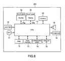
- Fig. 2 is a diagram showing a hardware structure of the portable information apparatus 100.
- the portable information apparatus 100 includes, in addition to the touch panels 2a and 2b (displays 25a and 25b) and the touch sensor 5, a CPU (Central Processing Unit) 11, a RAM (Random Access Memory) 12, and a flash memory 13.
- the portable information apparatus 100 also includes a communication portion 14, an external I/F (Interface) 15, a key/switch portion 16, a microphone 17, a speaker 18, a headphone 19, and a camera 20.
- the CPU 11 exchanges signals with the respective portions of the portable information apparatus 100 to perform various operations and collectively controls various types of display processing and other processing that correspond to touch operations made to the touch panels 2a and 2b.
- the RAM 12 is used as a working area of the CPU 11 and temporarily stores various types of data including images such as various icons to be processed by the CPU 11 and programs such as an application for executing the various types of display processing corresponding to the touch operations to the touch panels 2a and 2b.
- the flash memory 13 is of a NAND type, for example.
- the flash memory 13 stores various types of data including images such as various icons described above and various programs such as a control program to be executed by the CPU 11 and an application for executing the various types of display processing.
- the application may be stored in other recording media such as a memory card (not shown).
- the portable information apparatus 100 may include an HDD in place of or in addition to the flash memory 13.
- the communication portion 14 is an interface for connecting the portable information apparatus 100 to the Internet or a LAN (Local Area Network) according to a standard of the Ethernet (registered trademark), a wireless LAN, or the like.
- LAN Local Area Network
- the external I/F 15 exchanges various types of data via wired or wireless connection with an external apparatus based on various standards of a USB (Universal Serial Bus), a wireless LAN, and the like.
- the external I/F 15 may alternatively be an interface for connecting to various memory cards such as a memory stick.
- the key/switch portion 16 accepts operations corresponding to functions equivalent to functions that cannot be executed by an operation to the touch panels 2a and 2b, such as ON/OFF of a power source (not shown) and a switch of various functions, and functions that can be executed by an operation to the touch panels 2a and 2b, and transmits input signals to the CPU 11.
- the microphone 17 inputs audio such as a user voice for verbal communication in a case where the portable information apparatus 100 is connected to other apparatuses on a network by the communication portion 14.
- the speaker 18 and the headphone 19 output audio signals that are stored in the flash memory 13 or the like or input from the communication portion 14 or the microphone 17.
- the camera 20 captures a still image and a moving image by an image pickup device such as a CMOS (Complementary Metal Oxide Semiconductor) sensor and a CCD (Charge Coupled Device) sensor.
- an image pickup device such as a CMOS (Complementary Metal Oxide Semiconductor) sensor and a CCD (Charge Coupled Device) sensor.
- the captured data is stored in the RAM 12 or the flash memory 13 or transmitted to other apparatuses on the network via the communication portion 14.
- the "touch operation" in this embodiment includes not only a case where a finger of a user is physically in contact with the touch panels 2a and 2b and the touch sensor 5, but also a case where the finger of the user is brought close enough within a range in which a change in a capacitance can be detected.
- the portable information apparatus 100 also includes a cable and a flexible substrate for an electrical connection between the touch panels 2a and 2b.
- the cable and the flexible substrate may be provided across the gear members 3a and 3b and the coupling members 4.
- the displays 25a and 25b are, for example, an LCD of a TFT or the like or an OELD (Organic Electro-Luminescence Display) and display GUIs for touch operations such as an icon and a window and other images.
- the displays 25a and 25b are integrally formed with the touch panels 2a and 2b as described above.
- FIGs. 3 are diagrams showing opening and closing states of the portable information apparatus 100.
- Fig. 3A when the user lifts up the casing 1a in a state where the casings 1a and 1b are closed, for example, the gear members 3a and 3b and the coupling members 4 rotate to open the casing 1a as shown in Figs. 3B to 3D . Accordingly, the touch panels 2a and 2b are exposed. Then, as shown in Fig. 3E , the casings 1a and 1b become static when opened 180 degrees so that the touch surfaces of the touch panels 2a and 2b and the touch sensor 5 are positioned on the same plane. The touch operation of the user is input in the state shown in Fig. 3E . By thus setting the touch surfaces on the same plane, it becomes possible for the user to perform intuitional operations without being bothered by the different touch panels and the touch sensor.
- a drag-and-drop operation executed by the touch panels 2a and 2b of the portable information apparatus 100 will be described.
- the CPU 11 will be described as a subject of the operation, but the operation of the CPU 11 is executed in cooperation with programs developed in the RAM 12.
- Fig. 4 is a flowchart showing a flow of processing of the drag-and-drop operation by the portable information apparatus 100.
- Figs. 5 are diagrams showing an example of a state of the drag-and-drop operation by the portable information apparatus 100 seen from a direction of a plane of the touch panels 2a and 2b. Although a case where the user drags an object from the touch panel 2a to the touch panel 2b will be described in the figures, an operation in an opposite direction is of course executed in the same manner.
- the CPU 11 first displays an object O to be a target of a drag-and-drop operation by the user on the touch panel 2a (Step 41). Subsequently, the CPU 11 detects whether the object O has been dragged by a finger of the user (Step 42).
- Fig. 5A shows a state where the user is dragging the object O on the touch panel 2a.
- the CPU 11 judges whether the object O has been dragged to a lower end (end side 22) of the touch panel 2a and the touch operation has become undetected (Step 43). Specifically, the CPU 11 judges whether, in a coordinate system having an origin at a left end of the end side 22 in Figs. 5 , a Y coordinate of touch detection coordinates has become 0.
- the CPU 11 When judging that the drag operation that has been detected has become undetected at the end side 22 (YES), the CPU 11 subsequently judges whether a touch operation has been detected by the touch sensor 5 within m milliseconds since a time point at which the drag operation has become undetected (hereinafter, referred to as t1) (Step 44). m is, for example, about 50 to 500, though not limited thereto. When judging that the touch operation to the touch sensor 5 has not been detected within m milliseconds (NO), the CPU 11 ends the processing.
- Fig. 5B shows a state where the touch operation to the touch sensor 5 has been detected.
- the image may be, when the touch panels 2a and 2b are seen as a water surface, an animation like a ruffle on the water surface, for example.
- the image is not limited to that shown in the figure and may be any image as long as it indicates to the user that the object O is to be moved to the touch panel 2b. Accordingly, the user can grasp that the drag-and-drop operation from the touch panel 2a to the touch panel 2b is being executed for sure.
- the CPU 11 judges whether a touch operation has been detected at an upper end (end side 23) of the touch panel 2b within n milliseconds since a time point at which the touch operation to the touch sensor 5 has been detected (hereinafter, referred to as t2) (Step 46). Specifically, the CPU 11 judges whether a maximum value of a Y coordinate in a coordinate system of the touch panel 2b having an origin at a left end of the end side 24 in Figs. 5 has been detected within n milliseconds. n is, for example, about 50 to 500, though not limited thereto.
- the CPU 11 ends the processing.
- Fig. 5C shows a state where the object O is moved to and displayed on the touch panel 2b.
- the CPU 11 judges whether the touch operation has become undetected on the touch panel 2b (Step 48). Then, when judging that the touch operation has become undetected (YES), the CPU 11 stops moving (drops) the object O at a position at that time point (Step 49).
- the CPU 11 may alternatively display a part of the object O instead of the animation.
- Figs. 6 are diagrams showing a dragging state by the user in this case.
- the CPU 11 displays a partial upper portion O1 of the object O on the touch panel 2a and a partial lower portion 02 on the touch panel 2b.
- the partial lower portion 02 of the object O is displayed so as to stick out from the end side 23.
- Fig. 6C processes after that are the same as those of Figs. 5 .
- the user can grasp that the drag-and-drop operation from the touch panel 2a to the touch panel 2b is being executed for sure.
- the CPU 11 may alternatively display a part of the object O only on the touch panel 2b depending on an area of the object O.
- the touch panel 2a (2b) may be used on a cloud side, and the touch panel 2b (2a) may be used on a client side.
- An image downloaded from a computer of a cloud service provider on a network connected via the communication portion 14 is displayed on the cloud side, and an image of a file or the like stored in the portable information apparatus 100 is displayed on the client side.
- the user By drag-and-dropping an object from the cloud side to the client side, the user is capable of storing data corresponding to the object in the portable information apparatus 100 or updating data stored in the portable information apparatus 100.
- the user By drag-and-dropping an object from the client side to the cloud side, the user is capable of uploading data to a computer on the network or updating data in the computer.
- processing of exhibiting, by drag-and-dropping a window of a file displayed on the client side to the cloud side, the file to participants of the Web meeting may be executed.
- processing of setting a schedule of the user of the portable information apparatus 100 by drag-and-dropping an icon indicating a specific date on a calendar displayed on the cloud side to an area indicating the specific date on the calendar that is similarly displayed on the client side may be executed.
- the touch panel 2a (2b) may be used on a remote side, and the touch panel 2b (2a) may be used on a local side.
- a GUI for operating a file stored in another apparatus of the user on a LAN connected via the communication portion 14 is displayed on the remote side, and an image of a file or the like stored in the portable information apparatus 100 is displayed on the local side.
- the user By drag-and-dropping an object from the local side to the remote side, the user is capable of storing data of the portable information apparatus 100 in another apparatus or updating the data.
- the user By drag-and-dropping an object from the remote side to the local side, the user is capable of storing data of another apparatus in the portable information apparatus 100 or updating data in the portable information apparatus 100.
- the two touch panels 2a and 2b may be used for tasks in multitasking.
- the user can execute a plurality of tasks at the same time by drag-and-dropping an object alternately between the two touch panels 2a and 2b.
- the portable information apparatus 100 counts, after the drag operation on the touch panel 2a is detected, a time period from a time the touch operation has become undetected at the end side 22 (t1) to a time a touch operation is detected by the touch sensor 5 (t2). Further, the portable information apparatus 100 counts a time period from t2 to a time the touch operation is detected by the touch panel 2b. Then, when the time periods are within m and n milliseconds, respectively, the portable information apparatus 100 moves the object O to the touch panel 2b and displays it thereon. In other words, the portable information apparatus 100 moves the object to the touch panel 2b to display it thereon when a touch operation to the touch panel 2b is detected within (m+n) milliseconds since t1.
- the portable information apparatus 100 can positively execute the drag-and-drop operation of the object from the touch panel 2a to the touch panel 2b while preventing unintentional operations from being made.
- Fig. 7 is a diagram showing an outer appearance of a portable information apparatus of this embodiment.
- Fig. 8 is a diagram showing a hardware structure of the portable information apparatus of this embodiment.
- a portable information apparatus 200 of this embodiment is different from the portable information apparatus 100 of the first embodiment in the point of excluding a touch sensor. Specifically, an area between the touch panels 2a and 2b is formed as parts of the casings 1a and 1b as shown in Fig. 7 . Other structures of the portable information apparatus 200 are the same as those of the portable information apparatus 100.
- FIG. 9 is a flowchart showing a flow of processing of a drag-and-drop operation by the portable information apparatus 200 of this embodiment.
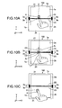
- Figs. 10 are diagrams showing an example of a state of the drag-and-drop operation by the portable information apparatus 200 of this embodiment seen from a direction of a plane of the touch panels 2a and 2b.
- the CPU 11 first displays the object O to be the target of the drag-and-drop operation by the user on the touch panel 2a (Step 91). Subsequently, the CPU 11 detects whether the object O has been dragged by a finger of the user (Step 92). These operations are the same as those of the first embodiment.
- the CPU 11 When detecting that the object O has been dragged (YES), the CPU 11 subsequently judges whether the object O has been dragged to the end side 22 of the touch panel 2a and the touch operation has become undetected (Step 93). Specifically, the CPU 11 judges whether the Y coordinate of the touch detection coordinates in the coordinate system of the touch panel 2a that is the same as that of the first embodiment has become 0.
- the CPU 11 When judging that the drag operation that has been detected has become undetected at the end side 22 (YES), the CPU 11 stores an X coordinate X 1 at a time point at which the drag operation has become undetected (hereinafter, referred to as t1) in, for example, the RAM 12 or the flash memory 13 (Step 94). Fig. 10A shows this case.
- the CPU 11 judges whether a touch operation has been detected at the upper end of the touch panel 2b within m milliseconds since t1 (Step 95). Specifically, the CPU 11 judges whether a maximum value of the Y coordinate has been detected within m milliseconds in the coordinate system of the touch panel 2b that is the same as that of the first embodiment. m is, for example, about 100 to 300, though not limited thereto.
- Step 95 the CPU 11 ends the processing.
- Step 96 the CPU 11 judges whether an X coordinate X 2 of the detection coordinates on the touch panel 2b and the stored X coordinate X 1 satisfy a relationship X 1-d ⁇ X 2 ⁇ X 1+d (Step 96).
- d is a predetermined distance and set as appropriate based on a distance between the end side 22 and the end side 23 in a Y direction in the figures, for example. In other words, d is set within a range that enables the operation to be judged as a natural drag operation from X 1 to X 2 .
- d is set so that an angle formed between a straight line connecting X 1 and X 2 and the end side 23 becomes 30° or more.
- the CPU 11 moves the object O from the touch panel 2a to the touch panel 2b and displays it thereon (Step 97).
- the CPU 11 may first display the partial upper portion O1 of the object O on the touch panel 2a and the partial lower portion 02 on the touch panel 2b as shown in Fig. 10B and then move the entire object O to the touch panel 2b as shown in Fig. 10C .
- the object O may gradually show itself after the partial lower portion 02 thereof is first displayed so as to stick out from the end side 23. Accordingly, the user can grasp that the drag-and-drop operation is being executed for sure across the touch panels 2a and 2b.
- the CPU 11 judges whether the touch operation has become undetected on the touch panel 2b as in the first embodiment (Step 98). Then, when judging that the touch operation has become undetected (YES), the CPU 11 stops moving (drops) the object O at a position at that time point (Step 99).
- the portable information apparatus 200 counts the time period from the time point at which the touch operation has become undetected on the touch panel 2a (t1) to the time point at which the touch operation is detected on the touch panel 2b.
- the portable information apparatus 200 also detects a difference between the X coordinate X 1 at the time point t1 and the X coordinate X 2 at the time point at which the touch operation is detected on the touch panel 2b. Then, the portable information apparatus 200 moves the object O from the touch panel 2a to the touch panel 2b and displays it thereon when the detection time period is within m milliseconds and the difference between X 1 and X 2 is smaller than d.
- the portable information apparatus 200 can positively execute the drag-and-drop operation from the touch panel 2a to the touch panel 2b.
- the present invention is not limited to the above embodiments and can be variously modified without departing from the gist of the present invention.
- the portable information apparatus 100 has displayed an image indicating a drag or the part 02 of the object O on the touch panel 2b when having detected the touch operation to the touch sensor 5.
- the portable information apparatus 100 may display the image or the part of the object on the touch panel 2b irrespective of whether the touch operation to the touch sensor 5 has been detected.
- the portable information apparatus 200 has displayed the part 02 of the object O on the touch panel 2b when having detected the touch operation to the touch panel 2b.
- the portable information apparatus 200 may display the part 02 of the object on the touch panel 2b even before detecting the touch operation to the touch panel 2b.
- the portable information apparatus 100 has moved the object to the touch panel 2b when detecting the touch operation to the touch panel 2b after detecting the touch operation to the touch sensor 5.
- the portable information apparatus 100 may move the object O to the touch panel 2b and display it thereon irrespective of whether the touch operation to the touch sensor 5 has been detected.
- the predetermined time period in this case is, for example, a time period shorter than m+n milliseconds described above.
- the portable information apparatus 100 can positively execute the drag-and-drop operation even when a touch operation to the touch sensor 5 cannot be detected for some reason like too fast a movement of a finger of a user, for example.
- the portable information apparatuses 100 and 200 have moved the object O to the touch panel 2b and displayed it thereon when having detected the touch operation to the touch sensor 5 or the touch panel 2b.
- the portable information apparatuses 100 and 200 it is also possible for the portable information apparatuses 100 and 200 to move the object O to the touch panel 2b and display it thereon when a drag velocity detected on the touch panel 2a exceeds a predetermined value. Accordingly, the portable information apparatuses 100 and 200 can positively execute a so-called flick (throwing object O) operation.
- the portable information apparatus 200 may include the touch sensor 5.
- the portable information apparatus 200 only needs to execute the processing of the first embodiment shown in Fig. 4 in combination with the processing of the second embodiment shown in Fig. 9 .
- the portable information apparatus 200 inserts the process of Step 94 of Fig. 9 between Steps 43 and 44 of Fig. 4 and executes it based on the processing shown in Fig. 4 .
- the portable information apparatus 200 only needs to execute the processes of Step 95 and the subsequent steps of Fig. 9 when it is judged in Step 44 of Fig. 4 that a touch has not been detected by the touch sensor 5 (NO).
- the portable information apparatus 200 can positively execute the drag-and-drop operation even when a touch cannot be detected by the touch sensor 5 for some reason.
- the above two embodiments have shown the examples in which two touch panels 2a and 2b are provided in the portable information apparatuses 100 and 200.
- the number of touch panels is not limited to 2 as long as it is plural, and the same processing as that described above can be executed across the touch panels.
- the touch operations to the touch panels 2a and 2b have been input with a finger of the user.
- the touch operations may be input with a device such as a stylus pen.
- Examples of the portable information apparatuses 100 and 200 to which the present invention can be applied in the above two embodiments include various information processing apparatuses such as a cellular phone, a PDA, a smartphone, a portable music/video player, an electronic dictionary, and an electronic organizer.
- the present invention is not limited to a portable information apparatus and is similarly applicable to various stationary information processing apparatuses.
Landscapes
- Engineering & Computer Science (AREA)
- Theoretical Computer Science (AREA)
- General Engineering & Computer Science (AREA)
- Human Computer Interaction (AREA)
- Physics & Mathematics (AREA)
- General Physics & Mathematics (AREA)
- Computer Hardware Design (AREA)
- User Interface Of Digital Computer (AREA)
- Position Input By Displaying (AREA)
Abstract
Description
- The present invention relates to an information processing apparatus including a plurality of touch panels, an information processing method for the information processing apparatus, and a program therefor.
- From the past, information processing apparatuses that each include a plurality of touch panels are known.
- For example, Japanese Patent Application Laid-open No.
2003-150273 Figs. 1 ,4 ,10 , etc.; hereinafter, referred to as Patent Document 1) discloses a watch-type PDA (Personal Digital Assistant) in which a plurality of panels including LCDs (Liquid Crystal Displays) integrally formed with a plurality of touch panels are connected by a hinge portion. - However, in the PDA disclosed in Patent Document 1, only an operation to a button displayed on each LCD is detected by the touch panel, and the PDA does not support an operation of moving an object by a touch operation. Least of all, the PDA is incapable of detecting a series of touch operations to the plurality of touch panels to cause the object to be drag-and-dropped across the plurality of touch panels.
- In view of the circumstances as described above, there is a need for an information processing apparatus, an information processing method, and a program therefor that are capable of executing a drag-and-drop operation of an object by positively detecting a series of touch operations across a plurality of touch panels.
- According to an embodiment of the present invention, there is provided an information processing apparatus including a first touch panel, a second touch panel, a touch sensor, and a controller. The first touch panel displays an object and detects a first touch operation of a user on the object. The second touch panel detects a second touch operation of the user. The touch sensor is provided between the first touch panel and the second touch panel and detects a third touch operation of the user. The controller moves the object displayed on the first touch panel in accordance with the first touch operation. Then, the controller displays the object on the second touch panel when the third touch operation is detected within a first time period since the first touch operation has become undetected and the second touch operation is detected within a second time period since the third touch operation is detected.
- With this structure, the information processing apparatus can execute a drag-and-drop operation across the first touch panel and the second touch panel by recognizing the second touch operation detected within a predetermined time period since the end of the first touch operation as a series of touch operations. Moreover, since the touch sensor is provided, the information processing apparatus is also capable of positively detecting the drag-and-drop operation and preventing an unintentional operation from being made.
- Here, the first and second touch panels include those that include a non-contact-type capacitance sensor, and the first and second touch operations include those that are not accompanied by a physical contact with respect to the first and second touch panels. Moreover, the object includes an icon, a window, and various other images.
- The controller may display, near the touch sensor, when the third touch operation is detected, an image indicating that the object is to be moved to the second touch panel.
- Here, the "image indicating that the object is to be moved" may indirectly indicate the movement by, when the second touch panel is seen as a water surface, for example, an animation such as a ripple or ruffle of the water surface. Alternatively, the image may directly indicate the movement with a part of an object, letters indicating the movement, and the like.
- Accordingly, the user can positively grasp that a drag operation of the object is to be executed across the two touch panels.
- The first touch panel may include a first touch surface having a first end side and a second end side opposed to the first end side. The second touch panel may include a second touch surface having a third end side adjacent to the second end side with the touch sensor interposed therebetween and a fourth end side opposed to the third end side. In this case, the controller may display, when the third touch operation is detected, the object such that a part of the object sticks out from the third end side of the second touch panel from the touch sensor side.
- With this structure, by displaying a part of the object on the second touch panel at a time of the drag operation, the user can more-positively grasp that the drag operation to the second touch panel is being executed.
- The first touch panel may include a first touch surface to which the first touch operation is input, the second touch panel may include a second touch surface to which the second touch operation is input, and the touch sensor may include a third touch surface to which the third touch operation is input. In this case, the first touch surface, the second touch surface, and the third touch surface may be provided so that the first touch surface, the second touch surface, and the third touch surface are positioned on the same plane at a time the first touch operation, the second touch operation, and the third touch operation are input.
- With this structure, the user can intuitionally perform a drag-and-drop operation from the first touch panel to the second touch panel via the touch sensor without being conscious of the panels and the touch sensor.
- The controller may detect a time period from a time the first touch operation is detected to a time the second touch operation is detected. Further, the controller may display, when the time period is a predetermined value or less, the object on the second touch panel irrespective of whether the third touch operation has been detected.
- With this structure, the information processing apparatus can move, when the drag operation has momentum, that is, when a movement velocity of a finger, a touch pen, and the like is high, the object to the second touch panel and display it thereon irrespective of whether the third touch operation has been detected. Therefore, even when the third touch operation is not detected although a drag-and-drop operation has been made, the information processing apparatus can positively execute the drag-and-drop operation.
- According to another embodiment of the present invention, there is provided an information processing apparatus including a first touch panel, a second touch panel, and a controller. The first touch panel displays an object and detects a first touch operation of a user on the object. The second touch panel is provided adjacent to the first touch panel in a first direction and detects a second touch operation of the user. The controller moves the object displayed on the first touch panel in accordance with the first touch operation and stores a first detection coordinate in a second direction orthogonal to the first direction, that is obtained at a time the first touch operation has become undetected. Further, the controller displays the object on the second touch panel when the second touch operation is detected within a predetermined time period since the first touch operation has become undetected and a second detection coordinate in the second direction obtained at the time the second touch operation is detected is within a predetermined range from the first detection coordinate.
- With this structure, when the first detection coordinate and the second detection coordinate are within the predetermined range, that is, are close to each other, the information processing apparatus can move the object assuming that a drag-and-drop operation has been made from the first touch panel to the second touch panel. Therefore, the information processing apparatus can prevent the object from being moved unintentionally when merely the first touch operation and the second touch operation are detected successively.
- Moreover, in this case, the first touch panel may include a first touch surface having a first end side and a second end side opposed to the first end side. The second touch panel may include a second touch surface having a third end side adjacent to the second end side and a fourth end side opposed to the third end side. In this case, the controller may display, when the second detection coordinate in the second direction is within the predetermined range from the first detection coordinate, the object such that a part of the object sticks out from the third end side of the second touch panel.
- With this structure, by displaying a part of the object on the second touch panel at the time of the drag operation, the user can more-positively grasp that the drag operation to the second touch panel is being executed.
- According to another embodiment of the present invention, there is provided an information processing method including displaying, by a first touch panel, an object and detecting a first touch operation of a user on the object, and detecting, by a second touch panel, a second touch operation of the user. The information processing method also includes detecting, by a touch sensor that is provided between the first touch panel and the second touch panel, a third touch operation of the user. The object displayed on the first touch panel is moved in accordance with the first touch operation, and the object is displayed on the second touch panel when the third touch operation is detected within a first time period since the first touch operation has become undetected and the second touch operation is detected within a second time period since the third touch operation is detected.
- By this method, the first touch operation to the first touch panel, the third touch operation to the touch sensor, and the second touch operation to the second touch panel can be recognized as a series of touch operations, and a drag-and-drop operation across the first and second touch panels is thus executed.
- According to another embodiment of the present invention, there is provided a program causing an information processing apparatus including a first touch panel, a second touch panel, and a touch sensor provided between the first touch panel and the second touch panel to execute a first detection step, a second detection step, a third detection step, and a control step. The first detection step includes displaying, by the first touch panel, an object and detecting a first touch operation of a user on the object. The second detection step includes detecting, by the second touch panel, a second touch operation of the user. The third detection step includes detecting, by the touch sensor, a third touch operation of the user. The control step includes moving the object displayed on the first touch panel in accordance with the first touch operation. The control step also includes displaying the object on the second touch panel when the third touch operation is detected within a first time period since the first touch operation has become undetected and the second touch operation is detected within a second time period since the third touch operation is detected.
- By this program, the first touch operation to the first touch panel, the third touch operation to the touch sensor, and the second touch operation to the second touch panel can be recognized as a series of touch operations, and a drag-and-drop operation across the first and second touch panels is thus executed.
- As described above, according to the embodiments of the present invention, a drag-and-drop operation of an object can be executed by positively detecting a series of touch operations across a plurality of touch panels.
- These and other objects, features and advantages of the present invention will become more apparent in light of the following detailed description of best mode embodiments thereof, as illustrated in the accompanying drawings.
-
-
Fig. 1 is a diagram showing an outer appearance of a portable information apparatus according to a first embodiment of the present invention; -
Fig. 2 is a diagram showing a hardware structure of the portable information apparatus according to the first embodiment of the present invention; -
Figs. 3 are diagrams showing opening and closing states of the portable information apparatus according to the first embodiment of the present invention; -
Fig. 4 is a flowchart showing a flow of processing of a drag-and-drop operation by the portable information apparatus according to the first embodiment of the present invention; -
Figs. 5 are diagrams showing an example of a state of the drag-and-drop operation by the portable information apparatus according to the first embodiment of the present invention seen from a direction of a plane of a touch panel; -
Figs. 6 are diagrams showing another example of a state of the drag-and-drop operation by the portable information apparatus according to the first embodiment of the present invention seen from the direction of the plane of the touch panel; -
Fig. 7 is a diagram showing an outer appearance of a portable information apparatus according to a second embodiment of the present invention; -
Fig. 8 is a diagram showing a hardware structure of the portable information apparatus according to the second embodiment of the present invention; -
Fig. 9 is a flowchart showing a flow of processing of a drag-and-drop operation by the portable information apparatus according to the second embodiment of the present invention; and -
Figs. 10 are diagrams showing an example of a state of the drag-and-drop operation by the portable information apparatus according to the second embodiment of the present invention seen from a direction of a plane of a touch panel. - Hereinafter, embodiments of the present invention will be described with reference to the drawings.
- First, a first embodiment of the present invention will be described.
-
Fig. 1 is a diagram showing an outer appearance of a portable information apparatus according to the first embodiment of the present invention. - As shown in the figure, a
portable information apparatus 100 includes a so-called clamshell-type casing 1 in which twocasings Fig. 1 shows a state where thecasings portable information apparatus 100 in this state. - The
casings touch panels touch panels displays touch panel 2a includes a touch surface having anend side 21 and anend side 22 opposed to theend side 21. Similarly, thetouch panel 2b includes a touch surface having anend side 23 and anend side 24 opposed to theend side 23. Thetouch panels displays - The
casing 1a includesgear members 3a on both side surfaces on theend side 22 side, and thecasing 1b includesgear members 3b on both side surfaces on theend side 23 side. Thegear members 3a and thegear members 3b are connected in an intermeshed state by couplingmembers 4. Thecoupling members 4 are each structured such that ends of two plates (or bars) are connected rotatably, and the other ends of the two plates (or bars) are connected to rotary axes of thegear members gear members coupling members 4, thecasings touch panel 2a of thecasing 1a and thetouch panel 2b of thecasing 1b can be brought closer to each other than in a case where thecasings - A
touch sensor 5 is provided between theend side 22 of thetouch panel 2a and theend side 23 of thetouch panel 2b. Thetouch sensor 5 includes atouch sensor portion 5a that is provided continuously on thecasing 1a from theend side 22 of thetouch panel 2a and atouch sensor portion 5b that is provided continuously on thecasing 1b from theend side 23 of thetouch panel 2b. The touch surface of thetouch panel 2a, the touch surface of thetouch panel 2b, and thetouch sensor 5 are provided so as to be positioned on the same plane when thecasings -
Fig. 2 is a diagram showing a hardware structure of theportable information apparatus 100. - As shown in the figure, the
portable information apparatus 100 includes, in addition to thetouch panels displays touch sensor 5, a CPU (Central Processing Unit) 11, a RAM (Random Access Memory) 12, and aflash memory 13. Theportable information apparatus 100 also includes acommunication portion 14, an external I/F (Interface) 15, a key/switch portion 16, amicrophone 17, aspeaker 18, aheadphone 19, and acamera 20. - The
CPU 11 exchanges signals with the respective portions of theportable information apparatus 100 to perform various operations and collectively controls various types of display processing and other processing that correspond to touch operations made to thetouch panels - The
RAM 12 is used as a working area of theCPU 11 and temporarily stores various types of data including images such as various icons to be processed by theCPU 11 and programs such as an application for executing the various types of display processing corresponding to the touch operations to thetouch panels - The
flash memory 13 is of a NAND type, for example. Theflash memory 13 stores various types of data including images such as various icons described above and various programs such as a control program to be executed by theCPU 11 and an application for executing the various types of display processing. The application may be stored in other recording media such as a memory card (not shown). Theportable information apparatus 100 may include an HDD in place of or in addition to theflash memory 13. - The
communication portion 14 is an interface for connecting theportable information apparatus 100 to the Internet or a LAN (Local Area Network) according to a standard of the Ethernet (registered trademark), a wireless LAN, or the like. - The external I/
F 15 exchanges various types of data via wired or wireless connection with an external apparatus based on various standards of a USB (Universal Serial Bus), a wireless LAN, and the like. The external I/F 15 may alternatively be an interface for connecting to various memory cards such as a memory stick. - The key/
switch portion 16 accepts operations corresponding to functions equivalent to functions that cannot be executed by an operation to thetouch panels touch panels CPU 11. - The
microphone 17 inputs audio such as a user voice for verbal communication in a case where theportable information apparatus 100 is connected to other apparatuses on a network by thecommunication portion 14. - The
speaker 18 and theheadphone 19 output audio signals that are stored in theflash memory 13 or the like or input from thecommunication portion 14 or themicrophone 17. - The
camera 20 captures a still image and a moving image by an image pickup device such as a CMOS (Complementary Metal Oxide Semiconductor) sensor and a CCD (Charge Coupled Device) sensor. The captured data is stored in theRAM 12 or theflash memory 13 or transmitted to other apparatuses on the network via thecommunication portion 14. - Although a resistance film system or a capacitance system is used as an operation system of the
touch panels touch sensor 5, other systems such as an electromagnetic induction system, a matrix switch system, a surface elastic wave system, and an infrared-ray system may be used instead. When the capacitance system is used as the operation system, the "touch operation" in this embodiment includes not only a case where a finger of a user is physically in contact with thetouch panels touch sensor 5, but also a case where the finger of the user is brought close enough within a range in which a change in a capacitance can be detected. - Though not shown, the
portable information apparatus 100 also includes a cable and a flexible substrate for an electrical connection between thetouch panels gear members coupling members 4. - The
displays displays touch panels - Next, an operation of the
portable information apparatus 100 structured as described above will be described. - First, an opening and closing operation of the
portable information apparatus 100 will be described.Figs. 3 are diagrams showing opening and closing states of theportable information apparatus 100. - As shown in
Fig. 3A , when the user lifts up thecasing 1a in a state where thecasings gear members coupling members 4 rotate to open thecasing 1a as shown inFigs. 3B to 3D . Accordingly, thetouch panels Fig. 3E , thecasings touch panels touch sensor 5 are positioned on the same plane. The touch operation of the user is input in the state shown inFig. 3E . By thus setting the touch surfaces on the same plane, it becomes possible for the user to perform intuitional operations without being bothered by the different touch panels and the touch sensor. - Next, a drag-and-drop operation executed by the
touch panels portable information apparatus 100 will be described. In descriptions below, theCPU 11 will be described as a subject of the operation, but the operation of theCPU 11 is executed in cooperation with programs developed in theRAM 12.Fig. 4 is a flowchart showing a flow of processing of the drag-and-drop operation by theportable information apparatus 100.Figs. 5 are diagrams showing an example of a state of the drag-and-drop operation by theportable information apparatus 100 seen from a direction of a plane of thetouch panels touch panel 2a to thetouch panel 2b will be described in the figures, an operation in an opposite direction is of course executed in the same manner. - As shown in
Fig. 4 , theCPU 11 first displays an object O to be a target of a drag-and-drop operation by the user on thetouch panel 2a (Step 41). Subsequently, theCPU 11 detects whether the object O has been dragged by a finger of the user (Step 42).Fig. 5A shows a state where the user is dragging the object O on thetouch panel 2a. - When judging that the object O has been dragged (YES), the
CPU 11 judges whether the object O has been dragged to a lower end (end side 22) of thetouch panel 2a and the touch operation has become undetected (Step 43). Specifically, theCPU 11 judges whether, in a coordinate system having an origin at a left end of theend side 22 inFigs. 5 , a Y coordinate of touch detection coordinates has become 0. - When judging that the drag operation that has been detected has become undetected at the end side 22 (YES), the
CPU 11 subsequently judges whether a touch operation has been detected by thetouch sensor 5 within m milliseconds since a time point at which the drag operation has become undetected (hereinafter, referred to as t1) (Step 44). m is, for example, about 50 to 500, though not limited thereto. When judging that the touch operation to thetouch sensor 5 has not been detected within m milliseconds (NO), theCPU 11 ends the processing. - When judging that the touch operation to the
touch sensor 5 has been detected within m milliseconds (YES), theCPU 11 displays on thetouch panel 2b an image that indicates that the object O is to be moved (dragged) to thetouch panel 2b (Step 45).Fig. 5B shows a state where the touch operation to thetouch sensor 5 has been detected. As shown inFig. 5B , the image may be, when thetouch panels touch panel 2b. Accordingly, the user can grasp that the drag-and-drop operation from thetouch panel 2a to thetouch panel 2b is being executed for sure. - Subsequently, the
CPU 11 judges whether a touch operation has been detected at an upper end (end side 23) of thetouch panel 2b within n milliseconds since a time point at which the touch operation to thetouch sensor 5 has been detected (hereinafter, referred to as t2) (Step 46). Specifically, theCPU 11 judges whether a maximum value of a Y coordinate in a coordinate system of thetouch panel 2b having an origin at a left end of theend side 24 inFigs. 5 has been detected within n milliseconds. n is, for example, about 50 to 500, though not limited thereto. When judging in Step 46 that the touch operation to thetouch panel 2b has not been detected within n milliseconds since t2 (NO), theCPU 11 ends the processing. - When judging that the touch operation to the
touch panel 2b has been detected within n milliseconds since t2 (YES), theCPU 11 moves the object O from thetouch panel 2a to thetouch panel 2b to display it thereon (Step 47).Fig. 5C shows a state where the object O is moved to and displayed on thetouch panel 2b. - After that, the
CPU 11 judges whether the touch operation has become undetected on thetouch panel 2b (Step 48). Then, when judging that the touch operation has become undetected (YES), theCPU 11 stops moving (drops) the object O at a position at that time point (Step 49). - As the image to be displayed in Step 45, the
CPU 11 may alternatively display a part of the object O instead of the animation.Figs. 6 are diagrams showing a dragging state by the user in this case. - As shown in
Figs. 6A and 6B , when the touch operation to thetouch sensor 5 is detected within m milliseconds since t1, theCPU 11 displays a partial upper portion O1 of the object O on thetouch panel 2a and a partiallower portion 02 on thetouch panel 2b. In other words, the partiallower portion 02 of the object O is displayed so as to stick out from theend side 23. As shown inFig. 6C , processes after that are the same as those ofFigs. 5 . Also in this case, the user can grasp that the drag-and-drop operation from thetouch panel 2a to thetouch panel 2b is being executed for sure. In this case, theCPU 11 may alternatively display a part of the object O only on thetouch panel 2b depending on an area of the object O. - The following operations can be exemplified as the drag-and-drop operation executed in this embodiment, though not limited thereto.
- (1) An operation of moving an image (object) such as an icon displayed on the
touch panel 2a (2b) and a window of an application that is being executed to thetouch panel 2b (2a) and displaying it thereon - (2) An operation of widely displaying, also on the
touch panel 2b (2a), an image (object) such as a window of an application that is being executed on thetouch panel 2a (2b) - Various applications are conceivable for applications of the two
touch panels - For example, the
touch panel 2a (2b) may be used on a cloud side, and thetouch panel 2b (2a) may be used on a client side. - An image downloaded from a computer of a cloud service provider on a network connected via the
communication portion 14 is displayed on the cloud side, and an image of a file or the like stored in theportable information apparatus 100 is displayed on the client side. By drag-and-dropping an object from the cloud side to the client side, the user is capable of storing data corresponding to the object in theportable information apparatus 100 or updating data stored in theportable information apparatus 100. On the other hand, by drag-and-dropping an object from the client side to the cloud side, the user is capable of uploading data to a computer on the network or updating data in the computer. - As a specific example of such an application, there is a case of holding a Web meeting with a user of another client apparatus via a service provider. In this case, processing of exhibiting, by drag-and-dropping a window of a file displayed on the client side to the cloud side, the file to participants of the Web meeting may be executed. Also processing of setting a schedule of the user of the
portable information apparatus 100 by drag-and-dropping an icon indicating a specific date on a calendar displayed on the cloud side to an area indicating the specific date on the calendar that is similarly displayed on the client side may be executed. - Alternatively, the
touch panel 2a (2b) may be used on a remote side, and thetouch panel 2b (2a) may be used on a local side. - A GUI for operating a file stored in another apparatus of the user on a LAN connected via the
communication portion 14 is displayed on the remote side, and an image of a file or the like stored in theportable information apparatus 100 is displayed on the local side. By drag-and-dropping an object from the local side to the remote side, the user is capable of storing data of theportable information apparatus 100 in another apparatus or updating the data. On the other hand, by drag-and-dropping an object from the remote side to the local side, the user is capable of storing data of another apparatus in theportable information apparatus 100 or updating data in theportable information apparatus 100. - Furthermore, the two
touch panels - In this case, the user can execute a plurality of tasks at the same time by drag-and-dropping an object alternately between the two
touch panels - As described heretofore, according to this embodiment, the
portable information apparatus 100 counts, after the drag operation on thetouch panel 2a is detected, a time period from a time the touch operation has become undetected at the end side 22 (t1) to a time a touch operation is detected by the touch sensor 5 (t2). Further, theportable information apparatus 100 counts a time period from t2 to a time the touch operation is detected by thetouch panel 2b. Then, when the time periods are within m and n milliseconds, respectively, theportable information apparatus 100 moves the object O to thetouch panel 2b and displays it thereon. In other words, theportable information apparatus 100 moves the object to thetouch panel 2b to display it thereon when a touch operation to thetouch panel 2b is detected within (m+n) milliseconds since t1. - Accordingly, the
portable information apparatus 100 can positively execute the drag-and-drop operation of the object from thetouch panel 2a to thetouch panel 2b while preventing unintentional operations from being made. - Next, a second embodiment of the present invention will be described. In this embodiment, structures and functions that are the same as those of the first embodiment above are denoted by the same symbols, and descriptions thereof will be omitted or simplified.
-
Fig. 7 is a diagram showing an outer appearance of a portable information apparatus of this embodiment.Fig. 8 is a diagram showing a hardware structure of the portable information apparatus of this embodiment. - As shown in the figures, a
portable information apparatus 200 of this embodiment is different from theportable information apparatus 100 of the first embodiment in the point of excluding a touch sensor. Specifically, an area between thetouch panels casings Fig. 7 . Other structures of theportable information apparatus 200 are the same as those of theportable information apparatus 100. - Next, an operation of the
portable information apparatus 200 structured as described above will be described.Fig. 9 is a flowchart showing a flow of processing of a drag-and-drop operation by theportable information apparatus 200 of this embodiment.Figs. 10 are diagrams showing an example of a state of the drag-and-drop operation by theportable information apparatus 200 of this embodiment seen from a direction of a plane of thetouch panels - As shown in
Fig. 9 , theCPU 11 first displays the object O to be the target of the drag-and-drop operation by the user on thetouch panel 2a (Step 91). Subsequently, theCPU 11 detects whether the object O has been dragged by a finger of the user (Step 92). These operations are the same as those of the first embodiment. - When detecting that the object O has been dragged (YES), the
CPU 11 subsequently judges whether the object O has been dragged to theend side 22 of thetouch panel 2a and the touch operation has become undetected (Step 93). Specifically, theCPU 11 judges whether the Y coordinate of the touch detection coordinates in the coordinate system of thetouch panel 2a that is the same as that of the first embodiment has become 0. - When judging that the drag operation that has been detected has become undetected at the end side 22 (YES), the
CPU 11 stores an X coordinate X1 at a time point at which the drag operation has become undetected (hereinafter, referred to as t1) in, for example, theRAM 12 or the flash memory 13 (Step 94).Fig. 10A shows this case. - Subsequently, the
CPU 11 judges whether a touch operation has been detected at the upper end of thetouch panel 2b within m milliseconds since t1 (Step 95). Specifically, theCPU 11 judges whether a maximum value of the Y coordinate has been detected within m milliseconds in the coordinate system of thetouch panel 2b that is the same as that of the first embodiment. m is, for example, about 100 to 300, though not limited thereto. When judging in Step 95 that the touch operation has not been detected at the upper end of thetouch panel 2b within m milliseconds (NO), theCPU 11 ends the processing. - When judging that the touch operation has been detected at the upper end of the
touch panel 2b within m milliseconds since t1 (YES), theCPU 11 judges whether an X coordinate X2 of the detection coordinates on thetouch panel 2b and the stored X coordinate X1 satisfy a relationship X1-d ≤ X2 ≤ X1+d (Step 96). Here, d is a predetermined distance and set as appropriate based on a distance between theend side 22 and theend side 23 in a Y direction in the figures, for example. In other words, d is set within a range that enables the operation to be judged as a natural drag operation from X1 to X2. When a difference between X1 and X2 is larger than d, it is judged that the operation made across thetouch panels end side 23 becomes 30° or more. When judging that d above does not satisfy the relationship (NO), theCPU 11 ends the processing. - When d satisfies the relationship, the
CPU 11 moves the object O from thetouch panel 2a to thetouch panel 2b and displays it thereon (Step 97). At this time, theCPU 11 may first display the partial upper portion O1 of the object O on thetouch panel 2a and the partiallower portion 02 on thetouch panel 2b as shown inFig. 10B and then move the entire object O to thetouch panel 2b as shown inFig. 10C . In other words, the object O may gradually show itself after the partiallower portion 02 thereof is first displayed so as to stick out from theend side 23. Accordingly, the user can grasp that the drag-and-drop operation is being executed for sure across thetouch panels - After that, the
CPU 11 judges whether the touch operation has become undetected on thetouch panel 2b as in the first embodiment (Step 98). Then, when judging that the touch operation has become undetected (YES), theCPU 11 stops moving (drops) the object O at a position at that time point (Step 99). - As described heretofore, according to this embodiment, the
portable information apparatus 200 counts the time period from the time point at which the touch operation has become undetected on thetouch panel 2a (t1) to the time point at which the touch operation is detected on thetouch panel 2b. Theportable information apparatus 200 also detects a difference between the X coordinate X1 at the time point t1 and the X coordinate X2 at the time point at which the touch operation is detected on thetouch panel 2b. Then, theportable information apparatus 200 moves the object O from thetouch panel 2a to thetouch panel 2b and displays it thereon when the detection time period is within m milliseconds and the difference between X1 and X2 is smaller than d. - Accordingly, even when the
touch sensor 5 is not provided unlike the first embodiment, theportable information apparatus 200 can positively execute the drag-and-drop operation from thetouch panel 2a to thetouch panel 2b. - The present invention is not limited to the above embodiments and can be variously modified without departing from the gist of the present invention.
- In the first embodiment above, the
portable information apparatus 100 has displayed an image indicating a drag or thepart 02 of the object O on thetouch panel 2b when having detected the touch operation to thetouch sensor 5. However, when the object O is dragged to an extent that it sticks out from theend side 22 of thetouch panel 2a, theportable information apparatus 100 may display the image or the part of the object on thetouch panel 2b irrespective of whether the touch operation to thetouch sensor 5 has been detected. - In the second embodiment above, the
portable information apparatus 200 has displayed thepart 02 of the object O on thetouch panel 2b when having detected the touch operation to thetouch panel 2b. However, when the object O is dragged to an extent that it sticks out from theend side 22 of thetouch panel 2a, theportable information apparatus 200 may display thepart 02 of the object on thetouch panel 2b even before detecting the touch operation to thetouch panel 2b. - In the first embodiment above, the
portable information apparatus 100 has moved the object to thetouch panel 2b when detecting the touch operation to thetouch panel 2b after detecting the touch operation to thetouch sensor 5. However, when the touch operation to thetouch panel 2b is detected within a predetermined time period since t1 above, theportable information apparatus 100 may move the object O to thetouch panel 2b and display it thereon irrespective of whether the touch operation to thetouch sensor 5 has been detected. The predetermined time period in this case is, for example, a time period shorter than m+n milliseconds described above. - Accordingly, the
portable information apparatus 100 can positively execute the drag-and-drop operation even when a touch operation to thetouch sensor 5 cannot be detected for some reason like too fast a movement of a finger of a user, for example. - In the above two embodiments, the
portable information apparatuses touch panel 2b and displayed it thereon when having detected the touch operation to thetouch sensor 5 or thetouch panel 2b. However, it is also possible for theportable information apparatuses touch panel 2b and display it thereon when a drag velocity detected on thetouch panel 2a exceeds a predetermined value. Accordingly, theportable information apparatuses - Although the
touch sensor 5 has not been provided in theportable information apparatus 200 in the second embodiment above, theportable information apparatus 200 may include thetouch sensor 5. In this case, theportable information apparatus 200 only needs to execute the processing of the first embodiment shown inFig. 4 in combination with the processing of the second embodiment shown inFig. 9 . In other words, theportable information apparatus 200 inserts the process of Step 94 ofFig. 9 between Steps 43 and 44 ofFig. 4 and executes it based on the processing shown inFig. 4 . On that basis, theportable information apparatus 200 only needs to execute the processes of Step 95 and the subsequent steps ofFig. 9 when it is judged in Step 44 ofFig. 4 that a touch has not been detected by the touch sensor 5 (NO). - By such processing, the
portable information apparatus 200 can positively execute the drag-and-drop operation even when a touch cannot be detected by thetouch sensor 5 for some reason. - The above two embodiments have shown the examples in which two
touch panels portable information apparatuses - In the above two embodiments, the touch operations to the
touch panels - Examples of the
portable information apparatuses - The present application contains subject matter related to that disclosed in Japanese Priority Patent Application
JP 2009-097722 - It should be understood by those skilled in the art that various modifications, combinations, sub-combinations and alterations may occur depending on design requirements and other factors insofar as they are within the scope of the appended claims or the equivalents thereof.
Claims (9)
- An information processing apparatus, comprising:a first touch panel to display an object and detect a first touch operation of a user on the object;a second touch panel to detect a second touch operation of the user;a touch sensor that is provided between the first touch panel and the second touch panel and detects a third touch operation of the user; anda controller to move the object displayed on the first touch panel in accordance with the first touch operation, and display the object on the second touch panel when the third touch operation is detected within a first time period since the first touch operation has become undetected and the second touch operation is detected within a second time period since the third touch operation is detected.
- The information processing apparatus according to claim 1,
wherein the controller displays, near the touch sensor, when the third touch operation is detected, an image indicating that the object is to be moved to the second touch panel. - The information processing apparatus according to claim 2,
wherein the first touch panel includes a first touch surface having a first end side and a second end side opposed to the first end side,
wherein the second touch panel includes a second touch surface having a third end side adjacent to the second end side with the touch sensor interposed therebetween and a fourth end side opposed to the third end side, and
wherein the controller displays, when the third touch operation is detected, the object such that a part of the object sticks out from the third end side of the second touch panel from the touch sensor side. - The information processing apparatus according to any of the preceding claims,
wherein the first touch panel includes a first touch surface to which the first touch operation is input,
wherein the second touch panel includes a second touch surface to which the second touch operation is input,
wherein the touch sensor includes a third touch surface to which the third touch operation is input, and
wherein the first touch surface, the second touch surface, and the third touch surface are provided so that the first touch surface, the second touch surface, and the third touch surface are positioned on the same plane at a time the first touch operation, the second touch operation, and the third touch operation are input. - The information processing apparatus according to any of the preceding claims,
wherein the controller detects a time period from a time the first touch operation is detected to a time the second touch operation is detected and displays, when the time period is a predetermined value or less, the object on the second touch panel irrespective of whether the third touch operation has been detected. - An information processing apparatus, comprising:a first touch panel to display an object and detect a first touch operation of a user on the object;a second touch panel that is provided adjacent to the first touch panel in a first direction and detects a second touch operation of the user; anda controller to move the object displayed on the first touch panel in accordance with the first touch operation, store a first detection coordinate in a second direction orthogonal to the first direction, that is obtained at a time the first touch operation has become undetected, and display the object on the second touch panel when the second touch operation is detected within a predetermined time period since the first touch operation has become undetected and a second detection coordinate in the second direction obtained at the time the second touch operation is detected is within a predetermined range from the first detection coordinate.
- The information processing apparatus according to claim 6,
wherein the first touch panel includes a first touch surface having a first end side and a second end side opposed to the first end side,
wherein the second touch panel includes a second touch surface having a third end side adjacent to the second end side and a fourth end side opposed to the third end side, and
wherein the controller displays, when the second detection coordinate in the second direction is within the predetermined range from the first detection coordinate, the object such that a part of the object sticks out from the third end side of the second touch panel. - An information processing method, comprising:displaying, by a first touch panel, an object and detecting a first touch operation of a user on the object;detecting, by a second touch panel, a second touch operation of the user;detecting, by a touch sensor that is provided between the first touch panel and the second touch panel, a third touch operation of the user; andmoving the object displayed on the first touch panel in accordance with the first touch operation, and displaying the object on the second touch panel when the third touch operation is detected within a first time period since the first touch operation has become undetected and the second touch operation is detected within a second time period since the third touch operation is detected.
- A program causing an information processing apparatus including a first touch panel, a second touch panel, and a touch sensor provided between the first touch panel and the second touch panel to execute the steps of:displaying, by the first touch panel, an object and detecting a first touch operation of a user on the object;detecting, by the second touch panel, a second touch operation of the user;detecting, by the touch sensor, a third touch operation of the user; andmoving the object displayed on the first touch panel in accordance with the first touch operation, and displaying the object on the second touch panel when the third touch operation is detected within a first time period since the first touch operation has become undetected and the second touch operation is detected within a second time period since the third touch operation is detected.
Applications Claiming Priority (1)
| Application Number | Priority Date | Filing Date | Title |
|---|---|---|---|
| JP2009097722A JP5606686B2 (en) | 2009-04-14 | 2009-04-14 | Information processing apparatus, information processing method, and program |
Publications (2)
| Publication Number | Publication Date |
|---|---|
| EP2241962A2 true EP2241962A2 (en) | 2010-10-20 |
| EP2241962A3 EP2241962A3 (en) | 2014-02-26 |
Family
ID=42269414
Family Applications (1)
| Application Number | Title | Priority Date | Filing Date |
|---|---|---|---|
| EP10002586.5A Withdrawn EP2241962A3 (en) | 2009-04-14 | 2010-03-11 | Information processing apparatus, information processing method, and program |
Country Status (6)
| Country | Link |
|---|---|
| US (1) | US8704781B2 (en) |
| EP (1) | EP2241962A3 (en) |
| JP (1) | JP5606686B2 (en) |
| CN (1) | CN101866238A (en) |
| BR (1) | BRPI1000982A2 (en) |
| RU (1) | RU2010113367A (en) |
Cited By (6)
| Publication number | Priority date | Publication date | Assignee | Title |
|---|---|---|---|---|
| US20100259494A1 (en) * | 2009-04-14 | 2010-10-14 | Sony Corporation | Information processing apparatus, information processing method, and program |
| WO2012108729A2 (en) | 2011-02-10 | 2012-08-16 | Samsung Electronics Co., Ltd. | Device including plurality of touch screens and screen change method for the device |
| WO2013064378A1 (en) * | 2011-10-31 | 2013-05-10 | Promethean Limited | Gui object manipulation prevention and over-ride |
| EP2677403A1 (en) * | 2011-02-16 | 2013-12-25 | NEC CASIO Mobile Communications, Ltd. | Information processing terminal, and method for controlling same |
| FR3003964A1 (en) * | 2013-04-02 | 2014-10-03 | Fogale Nanotech | DEVICE FOR INTERACTING, WITHOUT CONTACT, WITH AN ELECTRONIC AND / OR COMPUTER APPARATUS, AND APPARATUS PROVIDED WITH SUCH A DEVICE |
| WO2016197248A1 (en) | 2015-06-12 | 2016-12-15 | Nureva, Inc. | Method and apparatus for using gestures across multiple devices |
Families Citing this family (46)
| Publication number | Priority date | Publication date | Assignee | Title |
|---|---|---|---|---|
| US9207717B2 (en) | 2010-10-01 | 2015-12-08 | Z124 | Dragging an application to a screen using the application manager |
| US9213365B2 (en) | 2010-10-01 | 2015-12-15 | Z124 | Method and system for viewing stacked screen displays using gestures |
| JP4904375B2 (en) * | 2009-03-31 | 2012-03-28 | 京セラ株式会社 | User interface device and portable terminal device |
| KR101643377B1 (en) * | 2010-02-26 | 2016-07-28 | 삼성전자주식회사 | Foldable touch screen display apparatus |
| JP4865053B2 (en) * | 2010-04-22 | 2012-02-01 | 株式会社東芝 | Information processing apparatus and drag control method |
| US8810543B1 (en) * | 2010-05-14 | 2014-08-19 | Cypress Semiconductor Corporation | All points addressable touch sensing surface |
| US20110291964A1 (en) * | 2010-06-01 | 2011-12-01 | Kno, Inc. | Apparatus and Method for Gesture Control of a Dual Panel Electronic Device |
| CN101862238A (en) * | 2010-06-29 | 2010-10-20 | 覃叙钧 | Novel elastic waistline paper diaper |
| US8823656B2 (en) * | 2010-08-30 | 2014-09-02 | Atmel Corporation | Touch tracking across multiple touch screens |
| EP2622443B1 (en) | 2010-10-01 | 2022-06-01 | Z124 | Drag move gesture in user interface |
| US9052800B2 (en) | 2010-10-01 | 2015-06-09 | Z124 | User interface with stacked application management |
| JP5628625B2 (en) * | 2010-10-14 | 2014-11-19 | 京セラ株式会社 | Electronic device, screen control method, and screen control program |
| JP5629180B2 (en) * | 2010-10-21 | 2014-11-19 | 京セラ株式会社 | Mobile terminal device |
| US9213428B2 (en) | 2010-11-19 | 2015-12-15 | Blackberry Limited | Portable electronic device including flexible display |
| JP5968588B2 (en) * | 2010-11-26 | 2016-08-10 | 京セラ株式会社 | Electronics |
| JP5771401B2 (en) | 2011-01-27 | 2015-08-26 | 京セラ株式会社 | Mobile communication terminal |
| EP3734404A1 (en) | 2011-02-10 | 2020-11-04 | Samsung Electronics Co., Ltd. | Portable device comprising a touch-screen display, and method for controlling same |
| KR101842906B1 (en) | 2011-02-10 | 2018-05-15 | 삼성전자주식회사 | Apparatus having a plurality of touch screens and screen changing method thereof |
| JP5693305B2 (en) * | 2011-03-11 | 2015-04-01 | 京セラ株式会社 | Mobile terminal device |
| JP5709603B2 (en) * | 2011-03-28 | 2015-04-30 | 京セラ株式会社 | Portable terminal device, program, and display method |
| JP5884282B2 (en) * | 2011-03-29 | 2016-03-15 | ソニー株式会社 | Information processing apparatus, information processing method, recording medium, and program |
| JP5486540B2 (en) * | 2011-03-31 | 2014-05-07 | 株式会社Nttドコモ | Mobile terminal, data transmission system, and data transmission method |
| US8773374B2 (en) * | 2011-05-13 | 2014-07-08 | Blackberry Limited | Identification of touch point on touch screen device |
| JP2013008250A (en) * | 2011-06-24 | 2013-01-10 | Fujitsu Ltd | Cursor control device, cursor control method, and cursor control program |
| JP5751969B2 (en) * | 2011-07-26 | 2015-07-22 | 京セラ株式会社 | Electronic device, electronic device control method, and electronic device application program |
| JP5306430B2 (en) * | 2011-09-07 | 2013-10-02 | 京セラ株式会社 | Mobile terminal device |
| US8842057B2 (en) * | 2011-09-27 | 2014-09-23 | Z124 | Detail on triggers: transitional states |
| US20130125016A1 (en) * | 2011-11-11 | 2013-05-16 | Barnesandnoble.Com Llc | System and method for transferring content between devices |
| JP2013117885A (en) * | 2011-12-02 | 2013-06-13 | Nintendo Co Ltd | Information processing program, information processing equipment, information processing system and information processing method |
| US20130147702A1 (en) * | 2011-12-13 | 2013-06-13 | Nokia Corporation | Method, Apparatus, Computer Program and User Interface |
| JP2013235359A (en) * | 2012-05-08 | 2013-11-21 | Tokai Rika Co Ltd | Information processor and input device |
| JPWO2013175770A1 (en) | 2012-05-25 | 2016-01-12 | パナソニック インテレクチュアル プロパティ コーポレーション オブアメリカPanasonic Intellectual Property Corporation of America | Information processing apparatus, information processing method, and information processing program |
| JPWO2013175798A1 (en) | 2012-05-25 | 2016-01-12 | パナソニック インテレクチュアル プロパティ コーポレーション オブアメリカPanasonic Intellectual Property Corporation of America | Information processing apparatus, information processing method, and information processing program |
| KR101957173B1 (en) | 2012-09-24 | 2019-03-12 | 삼성전자 주식회사 | Method and apparatus for providing multi-window at a touch device |
| US9772722B2 (en) | 2012-10-22 | 2017-09-26 | Parade Technologies, Ltd. | Position sensing methods and devices with dynamic gain for edge positioning |
| JP6197327B2 (en) | 2013-03-27 | 2017-09-20 | 富士通株式会社 | Electronics |
| JP6169944B2 (en) * | 2013-10-22 | 2017-07-26 | アルパイン株式会社 | Touch panel device and operation detection method |
| JP2015127897A (en) * | 2013-12-27 | 2015-07-09 | ソニー株式会社 | Display control device, display control system, display control method, and program |
| US20150241978A1 (en) * | 2014-02-27 | 2015-08-27 | Motorola Mobility Llc | Electronic Device Having Multiple Sides with Gesture Sensors |
| JP2015194983A (en) * | 2014-03-25 | 2015-11-05 | パナソニックIpマネジメント株式会社 | Input device and display device |
| KR20160034135A (en) * | 2014-09-19 | 2016-03-29 | 삼성전자주식회사 | Device for Handling Touch Input and Method Thereof |
| CN106850719B (en) * | 2015-12-04 | 2021-02-05 | 珠海金山办公软件有限公司 | Data transmission method and device |
| US11157047B2 (en) * | 2018-11-15 | 2021-10-26 | Dell Products, L.P. | Multi-form factor information handling system (IHS) with touch continuity across displays |
| USD918898S1 (en) * | 2019-09-18 | 2021-05-11 | Robert Charles DeMaio | Electronic device |
| JP2021071959A (en) * | 2019-10-31 | 2021-05-06 | レノボ・シンガポール・プライベート・リミテッド | Information processing device and control method |
| CN112987957A (en) * | 2019-12-17 | 2021-06-18 | 群创光电股份有限公司 | Electronic device |
Citations (2)
| Publication number | Priority date | Publication date | Assignee | Title |
|---|---|---|---|---|
| JP2003150273A (en) | 2001-11-09 | 2003-05-23 | Sony Corp | Display unit |
| JP2009097722A (en) | 2007-10-16 | 2009-05-07 | Volvo Construction Equipment Ab | Hydraulic circuit for construction machinery |
Family Cites Families (23)
| Publication number | Priority date | Publication date | Assignee | Title |
|---|---|---|---|---|
| JP3177274B2 (en) * | 1991-11-19 | 2001-06-18 | シャープ株式会社 | Information processing device |
| JPH0644001A (en) | 1992-07-27 | 1994-02-18 | Toshiba Corp | Display controller and display control method |
| JP3876455B2 (en) * | 1996-05-21 | 2007-01-31 | ソニー株式会社 | Coordinate input apparatus and method |
| JP3304290B2 (en) * | 1997-06-26 | 2002-07-22 | シャープ株式会社 | Pen input device, pen input method, and computer readable recording medium recording pen input control program |
| US6331840B1 (en) * | 1998-03-27 | 2001-12-18 | Kevin W. Nielson | Object-drag continuity between discontinuous touch screens of a single virtual desktop |
| US6545669B1 (en) * | 1999-03-26 | 2003-04-08 | Husam Kinawi | Object-drag continuity between discontinuous touch-screens |
| US20040049743A1 (en) * | 2000-03-31 | 2004-03-11 | Bogward Glenn Rolus | Universal digital mobile device |
| US7170468B2 (en) * | 2001-02-21 | 2007-01-30 | International Business Machines Corporation | Collaborative tablet computer |
| US7453936B2 (en) * | 2001-11-09 | 2008-11-18 | Sony Corporation | Transmitting apparatus and method, receiving apparatus and method, program and recording medium, and transmitting/receiving system |
| US7136042B2 (en) * | 2002-10-29 | 2006-11-14 | Microsoft Corporation | Display controller permitting connection of multiple displays with a single video cable |
| CN101122808A (en) * | 2003-08-21 | 2008-02-13 | 阿尔卑斯电气株式会社 | Electronic device |
| US7532196B2 (en) * | 2003-10-30 | 2009-05-12 | Microsoft Corporation | Distributed sensing techniques for mobile devices |
| JP2005346583A (en) * | 2004-06-04 | 2005-12-15 | Canon Inc | Image display apparatus, multi-display system, coordinate information output method, and control program thereof |
| KR20070034767A (en) * | 2005-09-26 | 2007-03-29 | 엘지전자 주식회사 | Mobile communication terminal having multiple display areas and data display method between displays using same |
| US7844301B2 (en) * | 2005-10-14 | 2010-11-30 | Lg Electronics Inc. | Method for displaying multimedia contents and mobile communications terminal capable of implementing the same |
| US7636794B2 (en) * | 2005-10-31 | 2009-12-22 | Microsoft Corporation | Distributed sensing techniques for mobile devices |
| JP4650280B2 (en) | 2006-01-19 | 2011-03-16 | ソニー株式会社 | Display device and method, and program |
| US20090008161A1 (en) * | 2007-07-04 | 2009-01-08 | Jones Christopher W | Capacitive sensor array and gesture recognition |
| US20090322689A1 (en) * | 2008-06-30 | 2009-12-31 | Wah Yiu Kwong | Touch input across touch-sensitive display devices |
| JP2010176332A (en) * | 2009-01-28 | 2010-08-12 | Sony Corp | Information processing apparatus, information processing method, and program |
| JP4697558B2 (en) * | 2009-03-09 | 2011-06-08 | ソニー株式会社 | Information processing apparatus, information processing method, and information processing program |
| JP5606686B2 (en) * | 2009-04-14 | 2014-10-15 | ソニー株式会社 | Information processing apparatus, information processing method, and program |
| JP5229083B2 (en) * | 2009-04-14 | 2013-07-03 | ソニー株式会社 | Information processing apparatus, information processing method, and program |
-
2009
- 2009-04-14 JP JP2009097722A patent/JP5606686B2/en not_active Expired - Fee Related
-
2010
- 2010-02-18 US US12/708,099 patent/US8704781B2/en not_active Expired - Fee Related
- 2010-03-11 EP EP10002586.5A patent/EP2241962A3/en not_active Withdrawn
- 2010-03-31 CN CN201010157726A patent/CN101866238A/en active Pending
- 2010-04-06 RU RU2010113367/08A patent/RU2010113367A/en unknown
- 2010-04-07 BR BRPI1000982-5A patent/BRPI1000982A2/en not_active IP Right Cessation
Patent Citations (2)
| Publication number | Priority date | Publication date | Assignee | Title |
|---|---|---|---|---|
| JP2003150273A (en) | 2001-11-09 | 2003-05-23 | Sony Corp | Display unit |
| JP2009097722A (en) | 2007-10-16 | 2009-05-07 | Volvo Construction Equipment Ab | Hydraulic circuit for construction machinery |
Cited By (16)
| Publication number | Priority date | Publication date | Assignee | Title |
|---|---|---|---|---|
| US20100259494A1 (en) * | 2009-04-14 | 2010-10-14 | Sony Corporation | Information processing apparatus, information processing method, and program |
| US8704781B2 (en) * | 2009-04-14 | 2014-04-22 | Sony Corporation | Information processing apparatus, information processing method, and program |
| WO2012108729A2 (en) | 2011-02-10 | 2012-08-16 | Samsung Electronics Co., Ltd. | Device including plurality of touch screens and screen change method for the device |
| US10635295B2 (en) | 2011-02-10 | 2020-04-28 | Samsung Electronics Co., Ltd | Device including plurality of touch screens and screen change method for the device |
| AU2017272284B2 (en) * | 2011-02-10 | 2019-08-29 | Samsung Electronics Co., Ltd. | Device including plurality of touch screens and screen change method for the device |
| AU2012214930B2 (en) * | 2011-02-10 | 2017-09-07 | Samsung Electronics Co., Ltd | Device including plurality of touch screens and screen change method for the device |
| EP2673702A4 (en) * | 2011-02-10 | 2016-09-07 | Samsung Electronics Co Ltd | Device including plurality of touch screens and screen change method for the device |
| US9122337B2 (en) | 2011-02-16 | 2015-09-01 | Nec Corporation | Information processing terminal, and method for controlling same |
| EP2677403A4 (en) * | 2011-02-16 | 2014-10-01 | Nec Casio Mobile Comm Ltd | Information processing terminal, and method for controlling same |
| EP2677403A1 (en) * | 2011-02-16 | 2013-12-25 | NEC CASIO Mobile Communications, Ltd. | Information processing terminal, and method for controlling same |
| WO2013064378A1 (en) * | 2011-10-31 | 2013-05-10 | Promethean Limited | Gui object manipulation prevention and over-ride |
| WO2014161775A1 (en) * | 2013-04-02 | 2014-10-09 | Fogale Nanotech | Device for contactless interaction with an electronic and/or computer apparatus, and apparatus equipped with such a device |
| FR3003964A1 (en) * | 2013-04-02 | 2014-10-03 | Fogale Nanotech | DEVICE FOR INTERACTING, WITHOUT CONTACT, WITH AN ELECTRONIC AND / OR COMPUTER APPARATUS, AND APPARATUS PROVIDED WITH SUCH A DEVICE |
| WO2016197248A1 (en) | 2015-06-12 | 2016-12-15 | Nureva, Inc. | Method and apparatus for using gestures across multiple devices |
| EP3308259A4 (en) * | 2015-06-12 | 2019-01-23 | Nureva Inc. | Method and apparatus for using gestures across multiple devices |
| US11354009B2 (en) | 2015-06-12 | 2022-06-07 | Nureva, Inc. | Method and apparatus for using gestures across multiple devices |
Also Published As
| Publication number | Publication date |
|---|---|
| US8704781B2 (en) | 2014-04-22 |
| US20100259494A1 (en) | 2010-10-14 |
| CN101866238A (en) | 2010-10-20 |
| RU2010113367A (en) | 2011-10-20 |
| JP2010250463A (en) | 2010-11-04 |
| EP2241962A3 (en) | 2014-02-26 |
| JP5606686B2 (en) | 2014-10-15 |
| BRPI1000982A2 (en) | 2011-07-26 |
Similar Documents
| Publication | Publication Date | Title |
|---|---|---|
| US8704781B2 (en) | Information processing apparatus, information processing method, and program | |
| US9047046B2 (en) | Information processing apparatus, information processing method and program | |
| US10506153B2 (en) | Device and method for processing image in electronic device | |
| EP3232731B1 (en) | Mobile terminal | |
| US20200326839A1 (en) | Systems, Methods, and User Interfaces for Interacting with Multiple Application Windows | |
| US10331296B2 (en) | Multi-screen mobile device that launches applications into a revealed desktop | |
| US20180059891A1 (en) | Apparatus and method for providing a visual transition between screens | |
| US9411449B2 (en) | Mobile terminal and operation method therefor | |
| US20120180001A1 (en) | Electronic device and method of controlling same | |
| KR101343479B1 (en) | Electronic device and method of controlling same | |
| EP2779598A1 (en) | Method and apparatus for operating electronic device with cover | |
| KR20130124360A (en) | Electronic device and method of displaying information in response to a gesture | |
| JP5846129B2 (en) | Information processing terminal and control method thereof | |
| US20130162516A1 (en) | Apparatus and method for providing transitions between screens | |
| US20120274551A1 (en) | Electronic device, screen control method, and storage medium storing screen control program | |
| JP6213467B2 (en) | Terminal device, display control method, and program | |
| CN103809794A (en) | Information processing method and electronic device | |
| WO2013128512A1 (en) | Input device, input control method and program |
Legal Events
| Date | Code | Title | Description |
|---|---|---|---|
| PUAI | Public reference made under article 153(3) epc to a published international application that has entered the european phase |
Free format text: ORIGINAL CODE: 0009012 |
|
| 17P | Request for examination filed |
Effective date: 20100311 |
|
| AK | Designated contracting states |
Kind code of ref document: A2 Designated state(s): AT BE BG CH CY CZ DE DK EE ES FI FR GB GR HR HU IE IS IT LI LT LU LV MC MK MT NL NO PL PT RO SE SI SK SM TR |
|
| AX | Request for extension of the european patent |
Extension state: AL BA ME RS |
|
| PUAL | Search report despatched |
Free format text: ORIGINAL CODE: 0009013 |
|
| AK | Designated contracting states |
Kind code of ref document: A3 Designated state(s): AT BE BG CH CY CZ DE DK EE ES FI FR GB GR HR HU IE IS IT LI LT LU LV MC MK MT NL NO PL PT RO SE SI SK SM TR |
|
| AX | Request for extension of the european patent |
Extension state: AL BA ME RS |
|
| RIC1 | Information provided on ipc code assigned before grant |
Ipc: G06F 3/041 20060101ALI20140121BHEP Ipc: G06F 3/048 20130101AFI20140121BHEP |
|
| 17Q | First examination report despatched |
Effective date: 20140225 |
|
| STAA | Information on the status of an ep patent application or granted ep patent |
Free format text: STATUS: THE APPLICATION IS DEEMED TO BE WITHDRAWN |
|
| 18D | Application deemed to be withdrawn |
Effective date: 20151001 |