EP2241902B1 - Lokalisation eines mobilen Senders mit einer Schnittstelle Mensch/Maschine zum Auslösen der Lokalisationsvorgangs - Google Patents
Lokalisation eines mobilen Senders mit einer Schnittstelle Mensch/Maschine zum Auslösen der Lokalisationsvorgangs Download PDFInfo
- Publication number
- EP2241902B1 EP2241902B1 EP10003443A EP10003443A EP2241902B1 EP 2241902 B1 EP2241902 B1 EP 2241902B1 EP 10003443 A EP10003443 A EP 10003443A EP 10003443 A EP10003443 A EP 10003443A EP 2241902 B1 EP2241902 B1 EP 2241902B1
- Authority
- EP
- European Patent Office
- Prior art keywords
- location
- reference area
- probes
- handheld device
- magnetic field
- Prior art date
- Legal status (The legal status is an assumption and is not a legal conclusion. Google has not performed a legal analysis and makes no representation as to the accuracy of the status listed.)
- Not-in-force
Links
Images


Classifications
-
- G—PHYSICS
- G01—MEASURING; TESTING
- G01S—RADIO DIRECTION-FINDING; RADIO NAVIGATION; DETERMINING DISTANCE OR VELOCITY BY USE OF RADIO WAVES; LOCATING OR PRESENCE-DETECTING BY USE OF THE REFLECTION OR RERADIATION OF RADIO WAVES; ANALOGOUS ARRANGEMENTS USING OTHER WAVES
- G01S5/00—Position-fixing by co-ordinating two or more direction or position line determinations; Position-fixing by co-ordinating two or more distance determinations
- G01S5/02—Position-fixing by co-ordinating two or more direction or position line determinations; Position-fixing by co-ordinating two or more distance determinations using radio waves
- G01S5/08—Position of single direction-finder fixed by determining direction of a plurality of spaced sources of known location
-
- H—ELECTRICITY
- H04—ELECTRIC COMMUNICATION TECHNIQUE
- H04W—WIRELESS COMMUNICATION NETWORKS
- H04W64/00—Locating users or terminals or network equipment for network management purposes, e.g. mobility management
Definitions
- the invention relates to a method for detecting the location of an object within a reference area. More particularly, the invention relates to a method for locating a portable device emitting an electric field and / or a magnetic field within a reference area.
- Microsoft Surface® is an innovative human / machine interface that has recently been introduced and is described in US Patent Application No. 2006/0284874 .
- This patent application describes a method and a device for detecting one or more objects with respect to a display screen on which images (for example photos) are projected.
- An infrared light source directs infrared light toward the display screen.
- the infrared light is then reflected by objects on or near the display screen and this reflected light is captured by a digital video camera.
- the presence and / or movement of objects, such as the hands of a user are thus detected by the system, and a computer connected to the projector and the camera can calculate, by means of optical flow algorithms, what action should be performed and what should be displayed on the display screen.
- This application allows one or more users to perform actions such as translating, rotating, and resizing items projected on the display surface.
- NFC devices such as NFC PDAs or NFC mobile phones include an NFC reader that emits an RF magnetic field oscillating for example at 13.56 MHz.
- NFC Near Field Communication
- mobile phones conventionally, mobile phones also emit a UHF electromagnetic field having an electric field component to communicate with a mobile telephone network.
- Embodiments of the invention include the observation that electric fields or magnetic fields emitted by such portable devices can be used to detect their location or displacement within a reference area.
- Embodiments of the invention also include the observation that portable devices emitting an electric field or a magnetic field can be used as new types of human / machine interfaces to initiate interactive operations according to their location within a reference area.
- embodiments of the invention relate to a method for locating a portable emitting device emitting an electric field and / or a magnetic field, such as a mobile phone emitting an electric field or an NFC device emitting a field.
- magnetic method comprising the steps of: defining a reference area, having at least one electric field and / or magnetic field probe near or within the reference area, arranging the portable device to inside the reference area, receiving from the probe a detection signal of the electric field and / or the magnetic field emitted by the portable device, and analyzing the detection signal provided by the probe and deducing the location of the device portable within the reference area.
- the analysis of the detection signal comprises the steps of analyzing the amplitude of the detection signal to provide an amplitude value, and determining from the amplitude value the location of the detection signal. portable device within the reference area.
- the analysis of the detection signal comprises the steps of analyzing the phase of the detection signal to provide a phase value, and determining from the phase value the location of the portable device to inside the reference area.
- the method comprises the steps of: disposing at least two electric field and / or magnetic field probes near or within the reference area, receiving probes at least two signals of detecting and determining the location of the portable device within the reference area from the phase difference between the detection signals.
- the method comprises the steps of: disposing at least two electric field and / or magnetic field probes near or within the reference area, receiving probes at least two signals of detecting and determining the location of the portable device within the reference area from the amplitudes of the detection signals.
- the method comprises the steps of: arranging at least three electric field and / or magnetic field probes near or within the reference area, receiving probes at least three signals of detecting, determining a first phase difference between a first pair of detection signals, determining at least a second phase difference between a second pair of detection signals, and determining the location of the portable device within the area reference from the first and second phase differences.
- the method comprises the steps of: defining predetermined locations within the reference area, analyzing the detection signal provided by the probe, and deriving on which predetermined location the device is located portable.
- Embodiments of the invention also relate to a method for performing at least one interactive action, comprising a step of locating a portable device. transmitter within a reference area according to the method described above, and a step of initiating the interactive action according to the location of the portable device within the reference area.
- the initiation of the interactive action includes a step of providing interactive control signals to an external device configured to perform the interactive action.
- Embodiments of the invention also relate to a human / machine interface system for use with a portable device emitting an electric field and / or a magnetic field, such as a mobile phone emitting an electric field or an NFC device emitting a magnetic field, and comprising at least one electric field and / or magnetic field probe providing a detection signal, a location determining device, the location determining device being configured to analyze the detection signal, in deriving the location of the portable device within a reference area, and initiating at least one interactive action depending on the location of the portable device.
- a portable device emitting an electric field and / or a magnetic field such as a mobile phone emitting an electric field or an NFC device emitting a magnetic field, and comprising at least one electric field and / or magnetic field probe providing a detection signal, a location determining device, the location determining device being configured to analyze the detection signal, in deriving the location of the portable device within a reference area, and initiating at least one interactive action depending on the location of the portable device.
- the location determining device is configured to determine the location of the portable device from the amplitude value of the detection signal.
- the location determining device is configured to determine the location of the portable device from the phase value of the detection signal.
- the system comprises at least two electric field and / or magnetic field probes near or within the reference area, providing detection signals, and the location determining device is configured to determine the location of the portable device within the reference area from the phase difference between the detection signals.
- the system comprises at least two electric field and / or magnetic field probes near or within the reference area, providing detection signals, and the location determining device is configured to determine the location of the device portable within the reference area from the amplitudes of the detection signals.
- the system comprises at least three electric field and / or magnetic field probes near or within the reference area, the probes providing detection signals, and the device for determining the detection field. location is configured to determine a first phase difference between a first pair of sense signals, determine at least a second phase difference between a second pair of sense signals, and determine the location of the portable device within a second pair of sense signals; the reference area from the first and second phase differences.
- the location determining device is configured to store predetermined locations within the reference area, associating at least one interactive action at each predetermined location of the portable device, determining from the signal sensing on which predetermined location is located the portable device, and initiating the interactive action that is associated with the location of the portable device.
- the location determining device is configured to record, for each predetermined location, a set of amplitude and / or phase values of the detection signals when the portable device is placed on the location.
- Embodiments of a method for locating a portable transmitting device include the steps of defining a reference area and arranging electric field and / or magnetic field probes around the area of the invention. reference.
- a portable device emitting an electric field and / or a magnetic field is placed inside the reference area, and the probes provide detection signals.
- Each detection signal is the image of the electric or magnetic field emitted by the portable device as detected by the probe in question, and its amplitude and its phase depend on the distance between the portable device and the probe.
- the detection signals are used to determine the location of the portable device.
- the human-machine interface system receives detection signals provided by the probes and evaluates the location of the portable device within the the reference area. Operations may be assigned to the various locations on the reference area, and are executed when a user places the portable device at a certain location.
- a first embodiment of the method is illustrated on the figure 1 .
- a reference area RA1 is defined.
- the RA1 reference area can be on a surface such as a table or desk, the floor, a wall, etc. Therefore, it can be horizontal, vertical, or have any orientation or any shape, for example square, circular, etc.
- the reference area has a surface of the order of a few tens of square centimeters to a maximum of a few square meters, corresponding to the maximum amplitude of the movements that the user of the telephone can make with his arm and possibly his body, in a piece of usual dimensions.
- Two probes P1, P2 are arranged opposite each other on sides of the reference area RA1.
- the reference area RA1 is substantially a one-dimensional space along an axis X in which the probes P1, P2 are arranged.
- the reference area may be considered as a line coinciding with the X axis, or a fine rectangle aligned with the X axis, having a small width and a length equal to the distance between the probes P1, P2.
- the probes P1, P2 illustrated on the figure 1 are electric field probes.
- the probe P1 comprises, for example, a conducting wire W1 and a voltage probe EP1 in order to detect a voltage in the conducting wire.
- the probe P2 comprises a conducting wire W2 and an electric field probe EP2 in order to detect a voltage in the conducting wire W2.
- Probes P1, P2 are separated from each other by a known distance D12.
- the probes P1, P2 detect the electric field emitted by the portable device and provide detection signals S1, S2.
- Knowing the distance D12 makes it possible to determine the location of the portable device on the X axis without requiring a calibration step.
- the location of the portable device H1 can be determined by means of the phase difference between the signals S1, S2 or the difference in amplitude between the signals S1, S2, as will be explained later.
- D1 and D2 shall be determined.
- the amplitude of the signals detected by the probes is used to determine the location of the portable device.
- the probe P1 detects an amplitude signal M1 and the probe P2 detects a signal of amplitude M2.
- M0 being the maximum amplitude detected when the distance between the probes and the emitter object is zero
- K2 being a constant representing the slope of the function F which is determined by means of a calibration step.
- the figure 1 also illustrates an embodiment of a MMIS1 human / machine interface system implementing one or both of the methods described above.
- the MMIS1 system comprises probes P1, P2 and also includes an ADC1 analog-to-digital converter and a location determiner LDD1.
- the detection signals S1, S2 provided by the probes P1, P2 are digitized by the converter ADC1, which supplies the corresponding digitized signals DS1, DS2 to the device LDD1.
- the device LDD1 comprises an SD storage device containing programs and algorithms for analyzing the DS1, DS2 signals, extracting the phase difference or their amplitude or both, and executing algorithms to find the distances D1, D2 and so on. locate the portable device H1 according to at least one of the methods described above.
- a calibration step is performed in order to define the constant K2 or to define the amplitude M0 at a zero distance from the probes (see the equations alternatives 10 ', 11' above).
- the user must place the portable device in two different locations with respect to at least one probe, assuming that the probes are identical, in order to define K2.
- the user must place the portable device right next to at least one probe, in order to define M0.
- the device LDD1 may optionally be equipped with a display unit DU.
- the analog-digital converter ADC1 can also be part of the LDD1 device.
- the LDD1 device is a personal computer
- the SD storage device is a hard disk
- the display unit DU is a monitor.
- the monitor can have as interface a touch screen and / or the personal computer may also be equipped with an input member such as a keyboard (not shown).
- the device LDD1 provides interactive control signals IS1, IS2 ... ISi based on actions assigned to the various locations of the portable device. These control signals are used to initiate operations such as “Turn on the light”, “Turn off the light”, “Turn on the television”, “Turn off the television”, “Turn on the radio”, “Turn off the radio”, “Next slide” » « Previous slide »(for an image projection system during a presentation) etc. These operations are actions defined by the user, an administrator, or by the manufacturer or system vendor.
- a preliminary step may be performed before the system is used to define the actions to be performed when the portable device H1 is detected in the various locations of the reference area. It can consist of choosing actions from a predefined menu.
- the reference area could be divided into several different zones (not shown), such as a zone Z1 near the probe P1, a zone Z2 in the center, and a zone Z3 near the probe P2.
- each location can also be marked with symbols, photos, words, etc. to indicate to the user where to place the portable device for an action to be performed.
- Preconfigured templates for example an icon representing a light bulb to indicate that the light will turn on, can be provided.
- these models which may also indicate where to place the probes, may vary depending on the type of portable device to be used, the number of probes, the size and shape of the reference area, etc.
- Another example of use is to connect the home / machine interface system to an audio system or to light, and to use the movement of the portable device as a sliding switch to increase or decrease the volume or intensity of the light.
- the system MMIS1 is configured so that as the portable device is moved to the probe P1, the amplitude M1 increases as the amplitude M2 decreases and the volume or intensity of the light increases. Conversely, as the portable device is moved to the probe P2, the amplitude M2 increases as the amplitude M1 decreases, and the volume or intensity of the light decreases.
- the probes P1, P2 may also be magnetic field probes, for example antenna coils configured to detect a magnetic field emitted by a portable device comprising a NFC (Near Field Communication) controller.
- NFC Near Field Communication
- the wavelength ⁇ is equal to 22.1 m and represents the maximum distance between the P1 probes.
- P2 if the phase difference method is used to locate the portable device.
- a second embodiment of a method for locating a portable transmitter device within a reference area is illustrated on the Figure 2A .
- a two-dimensional reference area RA2 is defined. Locations are defined within the area with respect to an orthogonal coordinate system Oxy having a center O, an x-axis, and a y-axis.
- Two probes P1, P2 are arranged opposite each other on sides of the reference area RA2, at points F1, F2 which are for example located on the X axis (the x axis being for example defined as passing through F1, F2 ).
- Two other probes P3, P4 are arranged opposite each other on sides of the reference area RA2, for example at points F3, F4 located for example near the y-axis. It is assumed here that the respective x, y coordinates of the points F1, F2, F3, F4 are known.
- Probes P1-P4 are for example electric field probes of the type described above, or magnetic field probes configured to operate with an NFC portable device.
- the portable device H1 is then arranged inside the reference area RA2 at a point E1.
- the probes P1, P2, P3, P4 detect the electric field or the magnetic field emitted by the portable device and provide detection signals S1, S2, S3, S4.
- the location E1 of the portable device H1 is determined by means of the phase difference between the signals S1 and S2, S3 and S4.
- the hyperbola can be drawn in the Oxy plane as illustrated on the Figure 2A since ⁇ 1- ⁇ 2, ⁇ and K1 are known (or its points can be simply calculated by a location determination device).
- the hyperbole includes the curves H12, H12 '.
- the second hyperbola can also be drawn in the Oxy plane as illustrated on the Figure 2A , since ⁇ 1- ⁇ 2, ⁇ and K1 are known, or its calculated points.
- the hyperbola comprises the curves H34, H34 '.
- the determination of the actual location among the four possible locations is performed using the sign of the phase differences or the sign d differences between the magnitudes M1, M2, M3, M4 of the signals S1, S2, S3, S4 to determine in which quadrant of the plane Oxy is the desired intersection point, the four quadrants being for example defined as follows: x> 0 and y> 0, x> 0 and y ⁇ 0, x ⁇ 0 and y ⁇ 0, x ⁇ 0 and y> 0.
- the identification of the quadrant in which the portable device is located i.e., the quadrant in which the desired intersection point is located, is performed prior to searching for the intersection of the hyperbolas. , in order to simplify the calculation by avoiding having to look for the four points of intersection.
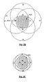
- the Figure 2B schematically illustrates the shape of the reference area RA2 obtained with the four probes situated at the points F1, F2, F3, F4, within which the distances D1, D2, D3 and D4 are less than or equal to the length of d wave ⁇ .
- the reference area RA2 is represented by a shaded area and corresponds to the intersection zone of four circles C1, C2, C3, C4 whose respective centers are the points F1, F2, F3, F4 and each having a radius R equal to ⁇ .
- the distance between F1 and F2 and the distance between F3 and F4 is close to ⁇ and F1-F4 are close to the boundaries of the reference area.
- Figure 2C schematically illustrates the shape of the reference area RA2 when the distance between F1 and F2 and the distance between F3 and F4 are well below ⁇ .
- F1, F2, F3, F4 lie within the reference area RA2.
- the embodiment of the method just described is capable of many other embodiments.
- the method can use the phase differences ⁇ 1- ⁇ 3, ⁇ 2- ⁇ 4 and the corresponding hyperbolas and their points of intersection, or the phase differences ⁇ 1- ⁇ 4, ⁇ 2- ⁇ 3 and the corresponding hyperbolas and their points of intersection.
- the method instead of using four probes, it is possible to use only three P1, P2, P3, and the method can use the phase differences ⁇ 1- ⁇ 3, ⁇ 2- ⁇ 3 and the corresponding hyperbolas and their dots. 'intersection.
- the hyperbola can be plotted in the Oxy plane if K2 is known (alternatively its points can be calculated by means of a location determination device).
- the second hyperbola can also be plotted in the Oxy plane, where its points are simply calculated. Once the hyperbolas are drawn or their points are simply calculated, four points of intersection E1, E1 ', E1 ", E1"' are found, as before.
- the point where the portable device is actually located here the point E1, must be chosen from the points E1, E1 ', E1 ", E1"'.
- the determination of the actual location between the four possible locations is made by using the sign of the differences between the amplitudes M1, M2, M3, M4 of the signals S1, S2, S3, S4 to determine in which quadrant of the plane Oxy is located the desired intersection point, or the sign of phase differences.
- the quadrant can also be determined before calculating the hyperbolas, in order to reduce the number of hyperbola points to calculate.
- the figure 3 illustrates another embodiment of a MMIS2 man / machine interface system configured to implement the second method described above.
- the MMIS2 system includes probes P1 to P4.
- the probes P1-P4 are probes of magnetic field, each comprising an AC1-AC4 antenna coil.
- the locations of the probes are stored in the LDD2 device, by the user or during system configuration at the factory.
- the probes P1-P4 may be dipole antennas configured to detect a UHF electric field emitted by a UHF reader (i.e. a reader provided for UHF transponders or contactless chips ).
- the MMIS2 system includes an ADC2 analog-to-digital converter, an LDD2 location determiner, and an optional SD storage unit and a DU display unit.
- the device LDD2 can also first look for the quadrant in which the portable device is located, then only find the point (s) of intersection of the hyperbolas that are in this quadrant.
- the device LDD2 provides interactive control signals IS1, IS2 ... ISi based on actions assigned to the various locations of the portable device.
- the control signals are used to initiate operations (see the examples described above).
- a preliminary step may be performed before the system is used to define the actions to be performed when the portable device H1 is detected in the various locations of the reference area.
- This step may consist of choosing actions from a predefined menu.
- the reference area could be divided into several different zones (not shown), for example ten different zones Z1 to Z10, each being assigned to a specific action.
- the MMIS2 system can measure the phase differences ⁇ 1- ⁇ 3, ⁇ 2- ⁇ 4 and determine the points of intersection of the corresponding hyperbolas, or measure the phase differences ⁇ 1- ⁇ 4, ⁇ 2- ⁇ 3 and determine the points of intersection of the corresponding hyperbolas.
- the MMIS2 system can comprise only three probes P1, P2, P3, and can be configured to measure the phase differences ⁇ 1- ⁇ 3, ⁇ 2- ⁇ 3 and determine the points of intersection of the corresponding hyperbolas.
- the MMIS2 system can also include more than four probes, for example ten probes arranged at various locations near the boundaries of the reference area.
- the method of locating the transmitting portable device may include a calibration step for storing different amplitude or phase values in relation to predetermined locations of the portable device.
- the user first defines the reference area RA1 or RA2 and arranges the probes P1, P2 or P1, P2, P3, or P1 to P4, on sides of the reference area. Then the user activates a configuration menu in the LDD1 or LDD2 device and provides him with a minimum of information such as the number of locations within the reference area that he wishes to define. and the number of probes.
- the LDD1 or LDD2 device then requests the user to place the portable device in the various locations declared, preferably keeping the same orientation of the portable device.
- Each probe detects the field emitted by the portable device.
- the digitized detection signals DS1, DS2 or DS1-DS3 or DS1-DS4 are analyzed by the device LDD1 or LDD2 in order to collect information concerning the difference in amplitude and / or phase of the signals S1, S2 or S1-S3 or S1-S4 in relation to each location. These measurements are preferably repeated until a set of values is collected for each probe and each location.
- the variations of the values measured in each location represent the variations that may be encountered during the operation of the device, for example if the user does not place the portable device at the locations with exactly the same orientation each time, or if various portable devices are used. .
- operations can be assigned to each location.
- the ability of the system to distinguish between different locations may be considered. For example, if the locations are too close together or there is not enough amplitude or phase difference between one location and another, the system may not be able to determine which operation the user wants to perform. . In this case, the user may request to choose a larger interval between locations by enlarging the size of the reference area or decreasing the number of locations within the reference area. Alternatively, the user could add additional probes or reposition the probes.
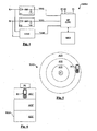
- the figure 4 illustrates a third embodiment of a human / machine interface system MMIS3 according to the invention (the reference area and the probes are not illustrated).
- the MMIS3 system comprises two integrators IT1, IT2, a phase difference detection module PDM1, a microprocessor MP, and a memory MEM.
- Each integrator IT1, IT2 comprises for example a diode, a resistor, a capacitor and a connection to ground.
- the integrators IT1, IT2 receive alternating detection signals (AC signals) S1, S2 of the probes P1, P2 and convert them into demodulated DC voltages (DC voltages) V (S1) and V (S2), the values of which depend on the amplitude of the signals S1, S2 and which are supplied to the microprocessor MP.
- AC signals alternating detection signals
- S1, S2 of the probes P1, P2 and convert them into demodulated DC voltages (DC voltages) V (S1) and V (S2), the values of which depend on the amplitude of the signals S
- the phase difference detection module PDM1 may be of analog or wired type.
- the microprocessor MP receives signals V (S1), V (S2), V ( ⁇ ) and performs the determination of the location according to at least one of the methods described above.
- the signals IS1, IS2 ... ISi are provided to external devices (not shown). In this embodiment, it is not necessary to digitize the signals S1, S2. Of course, it is possible to extend this embodiment to more than two probes by adding integrators and phase detection modules.
- the figure 5 illustrates an embodiment of the method according to the invention in which a single probe is used.
- a probe P1 is located at the center of a circular reference area RA3 with several circular and concentric locations, A01, A02, A03.
- the form The RA3 reference area circular allows, for example, several users around a table to use one H1 mobile phone one after the other to initiate various interactive actions.
- the figure 6 illustrates a probe P1 arranged on one side of a reference area RA4, which comprises several locations, for example A01, A02, A03 or more.
- the amplitude of the detected signal decreases as the portable device is moved away from the probe.
- the NFC portable devices are equipped with an NFC reader which emits a magnetic field and which can be detected by magnetic field probes, for example probes comprising detection antenna coils, Hall effect sensors etc.
- the location determining device LDD1, LDD2 performs further calculations to determine, based on the changes in locations of the portable device, the speed of movement, as well as the variations. speed (ie acceleration and deceleration). Actions are associated with a speed variation greater than a first threshold and / or less than a second threshold. For example, slowly moving the portable device to the P1 probe can move to the next slide of a visual presentation, while quickly move the portable device to the P1 probe can go directly to the end of the visual presentation.
- the portable device can also be an electronic token comprising a power source and for emitting an electric field, a field magnetic, or both.
- location may have different meanings depending on the embodiment of the invention, and that the term “area” should not be construed as being specifically limited to a one-dimensional space or two-dimensional.
- motion detection of the portable device may extend along axes that are perpendicular to the work surface, thereby defining a three-dimensional reference space.
- a mobile phone and an NFC device can be used within a single detection area, provided they do not operate exactly on the same frequency or that fields of different types are used to differentiate them, for example the electric field emitted by a mobile phone and the magnetic field emitted by an NFC mobile phone or an NFC device.
- the sets of values for the mobile phone are programmed to execute a certain set of interactive actions, while the sets of values for the phone or the NFC device are configured to perform a different set of interactive actions.
Landscapes
- Engineering & Computer Science (AREA)
- Physics & Mathematics (AREA)
- General Physics & Mathematics (AREA)
- Radar, Positioning & Navigation (AREA)
- Remote Sensing (AREA)
- Computer Networks & Wireless Communication (AREA)
- Signal Processing (AREA)
- Position Fixing By Use Of Radio Waves (AREA)
- Measurement Of Length, Angles, Or The Like Using Electric Or Magnetic Means (AREA)
Claims (13)
- Verfahren zur Durchführung wenigstens eines interaktiven Vorgangs anhand eines Mensch-Maschine-Schnittstellensystems, umfassend :- einen Schritt der Lokalisierung einer tragbaren Sendevorrichtung (H1), die ein Spannungsfeld und/oder ein Magnetfeld emittierende Kommunikationsmittel umfasst, wie ein ein Spannungsfeld emittierendes tragbares Mobiltelefon oder eine ein Magnetfeld emittierende NFC-Vorrichtung,dadurch gekennzeichnet, dass der Schritt der Lokalisierung Schritte umfasst, die darin bestehen:- eine Referenzfläche (RA1, RA2, RA3, RA4) einer Fläche in der Größenordnung von ein paar Dutzend Quadratzentimeter bis ein paar Quadratmeter zu definieren,- Plätze innerhalb der Referenzfläche zu definieren, und den verschiedenen Plätzen interaktive Vorgänge zuzuweisen,- wenigstens einen Spannungsfeld- und/oder Magnetfeld-Messkopf (P1-P4) in der Nähe von oder innerhalb der Referenzfläche anzuordnen,- einen interaktiven Vorgang auszuwählen, indem die tragbare Vorrichtung innerhalb der Referenzfläche (RA1, RA2, RA3, RA4) an einem dem interaktiven Vorgang entsprechenden Platz angeordnet wird,- ein vom Messkopf abgegebenes Signal (S1-S4) der Erfassung des von der tragbaren Vorrichtung emittierten Spannungsfelds und/oder Magnetfelds zu empfangen, und- das vom Messkopf abgegebene Erfassungssignal zu analysieren und daraus den Platz der tragbaren Vorrichtung innerhalb der Referenzfläche zu bestimmen,- anhand des Mensch-Maschine-Schnittstellensystems, den dem bestimmten Platz zugewiesenen interaktiven Vorgang zu initiieren, wobei der interaktive Vorgang einen Schritt umfasst, der darin besteht, interaktive Kontrollsignale (IS1, IS2...ISi) an eine externe Vorrichtung, die nicht die tragbare Vorrichtung und zur Durchführung des interaktiven Vorgangs konfiguriert ist, abzugeben.
- Verfahren nach Anspruch 1, bei dem die Analyse des Erfassungssignals Schritte umfasst, die darin bestehen, die Erfassungssignalamplitude zu analysieren, um einen Amplitudenwert zu erhalten, und den Platz der tragbaren Vorrichtung innerhalb der Referenzfläche aus dem Amplitudenwert zu bestimmen.
- Verfahren nach einem der Ansprüche 1 oder 2, bei dem die Analyse des Erfassungssignals Schritte umfasst, die darin bestehen, die Erfassungssignalphase zu analysieren, um einen Phasenwert zu erhalten, und den Platz der tragbaren Vorrichtung innerhalb der Referenzfläche aus dem Phasenwert zu bestimmen.
- Verfahren nach einem der Ansprüche 1 bis 3, umfassend Schritte, die darin bestehen:- wenigstens zwei Spannungsfeld- und/oder Magnetfeld-Messköpfe (P1-P4) in der Nähe von oder innerhalb der Referenzfläche (RA1-RA4) anzuordnen,- wenigstens zwei von den Messköpfen abgegebene Erfassungssignale (S1-S4) zu empfangen, und- den Platz der tragbaren Vorrichtung innerhalb der Referenzfläche aus der Phasendifferenz (ϕ1-ϕ2) zwischen den Erfassungssignalen zu bestimmen.
- Verfahren nach einem der Ansprüche 1 bis 4, umfassend Schritte, die darin bestehen:- wenigstens zwei Spannungsfeld- und/oder Magnetfeld-Messköpfe (P1-P4) in der Nähe von oder innerhalb der Referenzfläche (RA1-RA4) anzuordnen,- wenigstens zwei von den Messköpfen abgegebene Erfassungssignale (S1-S4) zu empfangen, und- den Platz der tragbaren Vorrichtung innerhalb der Referenzfläche aus den Erfassungssignalamplituden (M1-M4) zu bestimmen.
- Verfahren nach einem der Ansprüche 1 bis 4, umfassend Schritte, die darin bestehen:- wenigstens drei Spannungsfeld- und/oder Magnetfeld-Messköpfe (P1-P4) in der Nähe von oder innerhalb der Referenzfläche (RA1-RA4) anzuordnen,- wenigstens drei von den Messköpfen abgegebene Erfassungssignale (S1-S4) zu empfangen,- eine erste Phasendifferenz (ϕ1-ϕ2) zwischen einem ersten Paar (S1, S2) von Erfassungssignalen zu bestimmen,- wenigstens eine zweite Phasendifferenz (ϕ1-ϕ3, ϕ2-ϕ4) zwischen einem zweiten Paar (S1, S3; S3, S4) von Erfassungssignalen zu bestimmen, und- den Platz der tragbaren Vorrichtung innerhalb der Referenzfläche aus der ersten und der zweiten Phasendifferenz zu bestimmen.
- Mensch-Maschine-Schnittstellensystem (MMIS1, MMIS2) zur Verwendung mit einer tragbaren Vorrichtung (H1), die ein Spannungsfeld und/oder ein Magnetfeld emittierende Kommunikationsmittel umfasst, wie ein ein Spannungsfeld emittierendes tragbares Mobiltelefon oder eine ein Magnetfeld emittierende NFC-Vorrichtung, und umfassend:- wenigstens einen Spannungsfeld- und/oder Magnetfeld-Messkopf (P1-P4), d e r ein Erfassungssignal (S1-S4) abgibt,- eine Platzbestimmungsvorrichtung (LDD1, LDD2),dadurch gekennzeichnet, dass die Platzbestimmungsvorrichtung konfiguriert ist, um:- interaktive Vorgänge verschiedenen Plätzen innerhalb einer Referenzfläche einer Fläche in der Größenordnung von ein paar Dutzend Quadratzentimeter bis ein paar Quadratmeter zuzuweisen,- das vom Messkopf abgegebene Signal (S1-S4) der Erfassung des von der tragbaren Vorrichtung emittierten Spannungsfelds und/oder Magnetfelds zu empfangen,- das Erfassungssignal zu analysieren und daraus den Platz der tragbaren Vorrichtung innerhalb der Referenzfläche (RA1, RA2, RA3, RA4) zu bestimmen, und- wenigstens einen interaktiven dem bestimmten Platz zugewiesenen Vorgang zu initiieren, wobei der interaktive Vorgang einen Schritt umfasst, der darin besteht, interaktive Kontrollsignale (IS1, IS2...ISi) an eine externe Vorrichtung, die nicht die tragbare Vorrichtung und zur Durchführung des interaktiven Vorgangs konfiguriert ist, abzugeben,und das System es einem Benutzer ermöglicht, interaktive Vorgänge auszuwählen, indem die tragbare Vorrichtung an bestimmten, den interaktiven Vorgängen entsprechenden Plätzen innerhalb der Referenzfläche, angeordnet wird.
- Mensch-Maschine-Schnittstellensystem nach Anspruch 7, bei dem die Platzbestimmungsvorrichtung konfiguriert ist, um den Platz der tragbaren Vorrichtung aus dem Amplitudenwert des Erfassungssignals zu bestimmen.
- Mensch-Maschine-Schnittstellensystem nach einem der Ansprüche 7 oder 8, bei dem die Platzbestimmungsvorrichtung konfiguriert ist, um den Platz der tragbaren Vorrichtung aus dem Phasenwert des Erfassungssignals zu bestimmen.
- Mensch-Maschine-Schnittstellensystem nach einem der Ansprüche 7 bis 9, das wenigstens zwei Spannungsfeld - und/oder Magnetfeld-Messköpfe (P1-P4) in der Nähe von oder innerhalb der Referenzfläche (RA1-RA4) umfasst, das Erfassungssignale (S1-S4) abgibt, und bei dem die Platzbestimmungsvorrichtung konfiguriert ist, um den Platz der tragbaren Vorrichtung innerhalb der Referenzfläche aus der Phasendifferenz (ϕ1-ϕ2) zwischen den Erfassungssignalen zu bestimmen.
- Mensch-Maschine-Schnittstellensystem nach einem der Ansprüche 7 bis 10, das wenigstens zwei Spannungsfeld- und/oder Magnetfeld-Messköpfe (P1-P4) in der Nähe von oder innerhalb der Referenzfläche (RA1-RA4) umfasst, das Erfassungssignale (S1-S4) abgibt, und bei dem die Platzbestimmungsvorrichtung konfiguriert ist, um den Platz der tragbaren Vorrichtung innerhalb der Referenzfläche aus den Erfassungssignalamplituden (M1-M4) zu bestimmen.
- Mensch-Maschine-Schnittstellensystem nach einem der Ansprüche 7 bis 11, umfassend wenigstens drei Spannungsfeld- und/oder Magnetfeld-Messköpfe (P1-P4) in der Nähe von oder innerhalb der Referenzfläche (RA1-RA4), bei dem die Messköpfe Erfassungssignale (S1-S4) abgeben, und bei dem die Platzbestimmungsvorrichtung konfiguriert ist, um- eine erste Phasendifferenz (ϕ1-ϕ2) zwischen einem ersten Paar (S1, S2) von Erfassungssignalen zu bestimmen,- wenigstens eine zweite Phasendifferenz (ϕ1-ϕ3, ϕ2-ϕ4) zwischen einem zweiten Paar (S1, S3; S3, S4) von Erfassungssignalen zu bestimmen, und- den Platz der tragbaren Vorrichtung innerhalb der Referenzfläche aus der ersten und der zweiten Phasendifferenz zu bestimmen.
- Mensch-Maschine-Schnittstellensystem nach einem der Ansprüche 7 b i s 1 2, bei dem die Platzbestimmungsvorrichtung konfiguriert ist, um für jeden vorbestimmten Platz einen Satz von Amplituden - und/oder Phasenwerten der Erfassungssignale zu registrieren, wenn die tragbare Vorrichtung sich auf dem Platz befindet.
Applications Claiming Priority (1)
| Application Number | Priority Date | Filing Date | Title |
|---|---|---|---|
| FR0901658A FR2944109A1 (fr) | 2009-04-06 | 2009-04-06 | Localisation d'un objet portatif emettant un champ e ou h a l'interieur d'une aire de travail et de detection d'impact |
Publications (2)
| Publication Number | Publication Date |
|---|---|
| EP2241902A1 EP2241902A1 (de) | 2010-10-20 |
| EP2241902B1 true EP2241902B1 (de) | 2012-12-12 |
Family
ID=41394056
Family Applications (1)
| Application Number | Title | Priority Date | Filing Date |
|---|---|---|---|
| EP10003443A Not-in-force EP2241902B1 (de) | 2009-04-06 | 2010-03-30 | Lokalisation eines mobilen Senders mit einer Schnittstelle Mensch/Maschine zum Auslösen der Lokalisationsvorgangs |
Country Status (5)
| Country | Link |
|---|---|
| US (1) | US20100253532A1 (de) |
| EP (1) | EP2241902B1 (de) |
| KR (1) | KR101633808B1 (de) |
| CA (1) | CA2698404A1 (de) |
| FR (1) | FR2944109A1 (de) |
Families Citing this family (8)
| Publication number | Priority date | Publication date | Assignee | Title |
|---|---|---|---|---|
| DE102010033901B4 (de) * | 2010-08-10 | 2022-03-17 | Volkswagen Ag | Kraftfahrzeug mit einem Display zur Darstellung veränderlicher Informationen zur Bedienung von Funktionen des Kraftfahrzeuges |
| US9030303B2 (en) * | 2011-03-30 | 2015-05-12 | William Jay Hotaling | Contactless sensing and control system |
| DE102011107164B4 (de) * | 2011-07-13 | 2023-11-30 | Symeo Gmbh | Verfahren und System zur Ortung einer momentanen Position oder eines Einkoppelorts einer mobilen Einheit mittels Leckwellenleiters |
| US20130065212A1 (en) * | 2011-09-12 | 2013-03-14 | Mats Selen | Interactive online laboratory |
| WO2013100971A1 (en) * | 2011-12-28 | 2013-07-04 | Intel Corporation | Proximity detection via magnetic resonance coupling |
| US9496744B2 (en) * | 2012-12-20 | 2016-11-15 | Intel Corporation | Wireless charging optimization utilizing an NFC module that detects induced current and provides an indication of induced current |
| US20140266609A1 (en) * | 2013-03-15 | 2014-09-18 | Microchip Technology Incorporated | System and Method for Locating Wireless Nodes |
| CN105866858B (zh) * | 2016-03-25 | 2018-11-30 | 东莞市华盾电子科技有限公司 | 手机探测的标定方法、测试方法及其系统 |
Citations (1)
| Publication number | Priority date | Publication date | Assignee | Title |
|---|---|---|---|---|
| US20040203904A1 (en) * | 2002-12-27 | 2004-10-14 | Docomo Communications Laboratories Usa, Inc. | Selective fusion location estimation (SELFLOC) for wireless access technologies |
Family Cites Families (15)
| Publication number | Priority date | Publication date | Assignee | Title |
|---|---|---|---|---|
| US6414673B1 (en) * | 1998-11-10 | 2002-07-02 | Tidenet, Inc. | Transmitter pen location system |
| US6639585B1 (en) * | 1999-07-29 | 2003-10-28 | Brother Kogyo Kabushiki Kaisha | Coordinate reading device |
| US6300905B1 (en) * | 1999-10-05 | 2001-10-09 | Lucent Technologies Inc. | Location finding using a single base station in CDMA/TDMA systems |
| US8082096B2 (en) * | 2001-05-22 | 2011-12-20 | Tracbeam Llc | Wireless location routing applications and architecture therefor |
| US7538715B2 (en) * | 2004-10-04 | 2009-05-26 | Q-Track Corporation | Electromagnetic location and display system and method |
| GB0410610D0 (en) * | 2004-05-12 | 2004-06-16 | Nokia Corp | Locating mobile terminals |
| EP1786601A1 (de) * | 2004-06-24 | 2007-05-23 | Abb Ab | Industrierobotersystem mit einer tragbaren bedienungsvorrichtung |
| TWI263954B (en) * | 2005-05-27 | 2006-10-11 | Au Optronics Corp | Structure of a panel display device |
| US7535463B2 (en) | 2005-06-15 | 2009-05-19 | Microsoft Corporation | Optical flow-based manipulation of graphical objects |
| US7456596B2 (en) * | 2005-08-19 | 2008-11-25 | Cisco Technology, Inc. | Automatic radio site survey using a robot |
| JP4586690B2 (ja) * | 2005-09-09 | 2010-11-24 | 沖電気工業株式会社 | 位置推定システム |
| US7567627B1 (en) * | 2005-11-07 | 2009-07-28 | Raytheon Company | Estimating the location of a transmitter according to phase differences |
| US7940253B2 (en) * | 2006-08-17 | 2011-05-10 | Avago Technologies Ecbu Ip (Singapore) Pte. Ltd. | Method and system for screen navigation |
| US20080297319A1 (en) * | 2007-05-29 | 2008-12-04 | Semiconductor Energy Laboratory Co., Ltd. | Article management system |
| US7502619B1 (en) * | 2008-01-22 | 2009-03-10 | Katz Daniel A | Location determination of low power wireless devices over a wide area |
-
2009
- 2009-04-06 FR FR0901658A patent/FR2944109A1/fr active Pending
-
2010
- 2010-03-30 EP EP10003443A patent/EP2241902B1/de not_active Not-in-force
- 2010-03-31 CA CA2698404A patent/CA2698404A1/fr not_active Abandoned
- 2010-04-06 KR KR1020100031571A patent/KR101633808B1/ko not_active Expired - Fee Related
- 2010-04-06 US US12/755,048 patent/US20100253532A1/en not_active Abandoned
Patent Citations (1)
| Publication number | Priority date | Publication date | Assignee | Title |
|---|---|---|---|---|
| US20040203904A1 (en) * | 2002-12-27 | 2004-10-14 | Docomo Communications Laboratories Usa, Inc. | Selective fusion location estimation (SELFLOC) for wireless access technologies |
Also Published As
| Publication number | Publication date |
|---|---|
| CA2698404A1 (fr) | 2010-10-06 |
| US20100253532A1 (en) | 2010-10-07 |
| KR101633808B1 (ko) | 2016-07-08 |
| EP2241902A1 (de) | 2010-10-20 |
| KR20100111257A (ko) | 2010-10-14 |
| FR2944109A1 (fr) | 2010-10-08 |
Similar Documents
| Publication | Publication Date | Title |
|---|---|---|
| EP2241902B1 (de) | Lokalisation eines mobilen Senders mit einer Schnittstelle Mensch/Maschine zum Auslösen der Lokalisationsvorgangs | |
| US10621844B2 (en) | RFID reader and antenna system for locating items using a mobile device | |
| US11238513B1 (en) | Methods and device for implementing a virtual browsing experience | |
| US8953570B2 (en) | Radio frequency identification system and related operating methods | |
| CN111856073B (zh) | 基于分束自混合干涉测量传感器的颗粒物传感器 | |
| US9824384B2 (en) | Techniques for locating an item to purchase in a retail environment | |
| US20230079979A1 (en) | Determining relevant signals using multi-dimensional radar signals | |
| JP5987187B1 (ja) | 記憶媒体位置検出システム及びプログラム | |
| TW202009650A (zh) | 促進使用者與擴增實境介面中之顯示物件互動之簡易性及準確性之基於智慧型手機之雷達系統 | |
| US20170262134A1 (en) | Touch sensitive curved and flexible displays | |
| US20140337732A1 (en) | Music playback control with gesture detection using proximity or light sensors | |
| US20160231862A1 (en) | Identifying a target touch region of a touch-sensitive surface based on an image | |
| US11962096B2 (en) | Electronic device comprising antennas | |
| CN104871028B (zh) | 用于生成图像的方法以及手持式筛选装置 | |
| CN103885089A (zh) | 用于生成图像的方法及手提式筛分装置 | |
| US20170228092A1 (en) | Touch region projection onto touch-sensitive surface | |
| US20240053153A1 (en) | Target Localization Using AC Magnetic Fields | |
| US20230070733A1 (en) | Vernier Scan Architecture for Self-Mixing Interferometry Phase Measurements | |
| FR2959019A1 (fr) | Procede et dispositif de compensation d'une mesure d'un champ magnetique, procede et systeme de localisation d'un objet, support d'enregistrement pour ces procedes | |
| WO2015159547A1 (ja) | 情報処理システム、制御方法、及びプログラム記録媒体 | |
| CN107077196B (zh) | 识别触敏表面上的对象 | |
| FR3049144B1 (fr) | Agencement pour, et procede d'analyse d'une couverture de champ de reseau local sans fil (wlan) dans un lieu | |
| EP3258287B1 (de) | Vorrichtung und entsprechende verfahren zur standortbestimmung | |
| US20250271777A1 (en) | Determining an optimal configuration for a metrology system | |
| WO2023244816A1 (en) | Reference point for configuring an object counter |
Legal Events
| Date | Code | Title | Description |
|---|---|---|---|
| PUAI | Public reference made under article 153(3) epc to a published international application that has entered the european phase |
Free format text: ORIGINAL CODE: 0009012 |
|
| AK | Designated contracting states |
Kind code of ref document: A1 Designated state(s): AT BE BG CH CY CZ DE DK EE ES FI FR GB GR HR HU IE IS IT LI LT LU LV MC MK MT NL NO PL PT RO SE SI SK SM TR |
|
| AX | Request for extension of the european patent |
Extension state: AL BA ME RS |
|
| 17P | Request for examination filed |
Effective date: 20110414 |
|
| RAP1 | Party data changed (applicant data changed or rights of an application transferred) |
Owner name: INSIDE SECURE |
|
| 17Q | First examination report despatched |
Effective date: 20111213 |
|
| GRAP | Despatch of communication of intention to grant a patent |
Free format text: ORIGINAL CODE: EPIDOSNIGR1 |
|
| GRAS | Grant fee paid |
Free format text: ORIGINAL CODE: EPIDOSNIGR3 |
|
| GRAA | (expected) grant |
Free format text: ORIGINAL CODE: 0009210 |
|
| AK | Designated contracting states |
Kind code of ref document: B1 Designated state(s): AT BE BG CH CY CZ DE DK EE ES FI FR GB GR HR HU IE IS IT LI LT LU LV MC MK MT NL NO PL PT RO SE SI SK SM TR |
|
| REG | Reference to a national code |
Ref country code: GB Ref legal event code: FG4D Free format text: NOT ENGLISH |
|
| REG | Reference to a national code |
Ref country code: CH Ref legal event code: EP |
|
| REG | Reference to a national code |
Ref country code: AT Ref legal event code: REF Ref document number: 588555 Country of ref document: AT Kind code of ref document: T Effective date: 20121215 |
|
| REG | Reference to a national code |
Ref country code: IE Ref legal event code: FG4D Free format text: LANGUAGE OF EP DOCUMENT: FRENCH |
|
| REG | Reference to a national code |
Ref country code: DE Ref legal event code: R096 Ref document number: 602010004007 Country of ref document: DE Effective date: 20130207 |
|
| PG25 | Lapsed in a contracting state [announced via postgrant information from national office to epo] |
Ref country code: SE Free format text: LAPSE BECAUSE OF FAILURE TO SUBMIT A TRANSLATION OF THE DESCRIPTION OR TO PAY THE FEE WITHIN THE PRESCRIBED TIME-LIMIT Effective date: 20121212 Ref country code: ES Free format text: LAPSE BECAUSE OF FAILURE TO SUBMIT A TRANSLATION OF THE DESCRIPTION OR TO PAY THE FEE WITHIN THE PRESCRIBED TIME-LIMIT Effective date: 20130323 Ref country code: FI Free format text: LAPSE BECAUSE OF FAILURE TO SUBMIT A TRANSLATION OF THE DESCRIPTION OR TO PAY THE FEE WITHIN THE PRESCRIBED TIME-LIMIT Effective date: 20121212 Ref country code: NO Free format text: LAPSE BECAUSE OF FAILURE TO SUBMIT A TRANSLATION OF THE DESCRIPTION OR TO PAY THE FEE WITHIN THE PRESCRIBED TIME-LIMIT Effective date: 20130312 Ref country code: HR Free format text: LAPSE BECAUSE OF FAILURE TO SUBMIT A TRANSLATION OF THE DESCRIPTION OR TO PAY THE FEE WITHIN THE PRESCRIBED TIME-LIMIT Effective date: 20121212 Ref country code: LT Free format text: LAPSE BECAUSE OF FAILURE TO SUBMIT A TRANSLATION OF THE DESCRIPTION OR TO PAY THE FEE WITHIN THE PRESCRIBED TIME-LIMIT Effective date: 20121212 |
|
| REG | Reference to a national code |
Ref country code: NL Ref legal event code: VDEP Effective date: 20121212 |
|
| REG | Reference to a national code |
Ref country code: AT Ref legal event code: MK05 Ref document number: 588555 Country of ref document: AT Kind code of ref document: T Effective date: 20121212 |
|
| REG | Reference to a national code |
Ref country code: LT Ref legal event code: MG4D |
|
| PG25 | Lapsed in a contracting state [announced via postgrant information from national office to epo] |
Ref country code: GR Free format text: LAPSE BECAUSE OF FAILURE TO SUBMIT A TRANSLATION OF THE DESCRIPTION OR TO PAY THE FEE WITHIN THE PRESCRIBED TIME-LIMIT Effective date: 20130313 Ref country code: LV Free format text: LAPSE BECAUSE OF FAILURE TO SUBMIT A TRANSLATION OF THE DESCRIPTION OR TO PAY THE FEE WITHIN THE PRESCRIBED TIME-LIMIT Effective date: 20121212 Ref country code: SI Free format text: LAPSE BECAUSE OF FAILURE TO SUBMIT A TRANSLATION OF THE DESCRIPTION OR TO PAY THE FEE WITHIN THE PRESCRIBED TIME-LIMIT Effective date: 20121212 |
|
| PG25 | Lapsed in a contracting state [announced via postgrant information from national office to epo] |
Ref country code: SK Free format text: LAPSE BECAUSE OF FAILURE TO SUBMIT A TRANSLATION OF THE DESCRIPTION OR TO PAY THE FEE WITHIN THE PRESCRIBED TIME-LIMIT Effective date: 20121212 Ref country code: BG Free format text: LAPSE BECAUSE OF FAILURE TO SUBMIT A TRANSLATION OF THE DESCRIPTION OR TO PAY THE FEE WITHIN THE PRESCRIBED TIME-LIMIT Effective date: 20130312 Ref country code: IS Free format text: LAPSE BECAUSE OF FAILURE TO SUBMIT A TRANSLATION OF THE DESCRIPTION OR TO PAY THE FEE WITHIN THE PRESCRIBED TIME-LIMIT Effective date: 20130412 Ref country code: CZ Free format text: LAPSE BECAUSE OF FAILURE TO SUBMIT A TRANSLATION OF THE DESCRIPTION OR TO PAY THE FEE WITHIN THE PRESCRIBED TIME-LIMIT Effective date: 20121212 Ref country code: EE Free format text: LAPSE BECAUSE OF FAILURE TO SUBMIT A TRANSLATION OF THE DESCRIPTION OR TO PAY THE FEE WITHIN THE PRESCRIBED TIME-LIMIT Effective date: 20121212 Ref country code: AT Free format text: LAPSE BECAUSE OF FAILURE TO SUBMIT A TRANSLATION OF THE DESCRIPTION OR TO PAY THE FEE WITHIN THE PRESCRIBED TIME-LIMIT Effective date: 20121212 |
|
| PG25 | Lapsed in a contracting state [announced via postgrant information from national office to epo] |
Ref country code: PL Free format text: LAPSE BECAUSE OF FAILURE TO SUBMIT A TRANSLATION OF THE DESCRIPTION OR TO PAY THE FEE WITHIN THE PRESCRIBED TIME-LIMIT Effective date: 20121212 Ref country code: RO Free format text: LAPSE BECAUSE OF FAILURE TO SUBMIT A TRANSLATION OF THE DESCRIPTION OR TO PAY THE FEE WITHIN THE PRESCRIBED TIME-LIMIT Effective date: 20121212 Ref country code: PT Free format text: LAPSE BECAUSE OF FAILURE TO SUBMIT A TRANSLATION OF THE DESCRIPTION OR TO PAY THE FEE WITHIN THE PRESCRIBED TIME-LIMIT Effective date: 20130412 Ref country code: NL Free format text: LAPSE BECAUSE OF FAILURE TO SUBMIT A TRANSLATION OF THE DESCRIPTION OR TO PAY THE FEE WITHIN THE PRESCRIBED TIME-LIMIT Effective date: 20121212 |
|
| BERE | Be: lapsed |
Owner name: INSIDE SECURE Effective date: 20130331 |
|
| PLBE | No opposition filed within time limit |
Free format text: ORIGINAL CODE: 0009261 |
|
| STAA | Information on the status of an ep patent application or granted ep patent |
Free format text: STATUS: NO OPPOSITION FILED WITHIN TIME LIMIT |
|
| PG25 | Lapsed in a contracting state [announced via postgrant information from national office to epo] |
Ref country code: MC Free format text: LAPSE BECAUSE OF NON-PAYMENT OF DUE FEES Effective date: 20130331 Ref country code: DK Free format text: LAPSE BECAUSE OF FAILURE TO SUBMIT A TRANSLATION OF THE DESCRIPTION OR TO PAY THE FEE WITHIN THE PRESCRIBED TIME-LIMIT Effective date: 20121212 |
|
| 26N | No opposition filed |
Effective date: 20130913 |
|
| PG25 | Lapsed in a contracting state [announced via postgrant information from national office to epo] |
Ref country code: CY Free format text: LAPSE BECAUSE OF FAILURE TO SUBMIT A TRANSLATION OF THE DESCRIPTION OR TO PAY THE FEE WITHIN THE PRESCRIBED TIME-LIMIT Effective date: 20121212 |
|
| REG | Reference to a national code |
Ref country code: FR Ref legal event code: CA Effective date: 20131112 |
|
| PG25 | Lapsed in a contracting state [announced via postgrant information from national office to epo] |
Ref country code: IT Free format text: LAPSE BECAUSE OF FAILURE TO SUBMIT A TRANSLATION OF THE DESCRIPTION OR TO PAY THE FEE WITHIN THE PRESCRIBED TIME-LIMIT Effective date: 20121212 |
|
| REG | Reference to a national code |
Ref country code: IE Ref legal event code: MM4A |
|
| REG | Reference to a national code |
Ref country code: DE Ref legal event code: R081 Ref document number: 602010004007 Country of ref document: DE Owner name: INSIDE SECURE, FR Free format text: FORMER OWNER: INSIDE SECURE, AIX-EN-PROVENCE, FR Effective date: 20131111 |
|
| REG | Reference to a national code |
Ref country code: DE Ref legal event code: R097 Ref document number: 602010004007 Country of ref document: DE Effective date: 20130913 |
|
| PG25 | Lapsed in a contracting state [announced via postgrant information from national office to epo] |
Ref country code: BE Free format text: LAPSE BECAUSE OF NON-PAYMENT OF DUE FEES Effective date: 20130331 Ref country code: IE Free format text: LAPSE BECAUSE OF NON-PAYMENT OF DUE FEES Effective date: 20130330 |
|
| PG25 | Lapsed in a contracting state [announced via postgrant information from national office to epo] |
Ref country code: MT Free format text: LAPSE BECAUSE OF FAILURE TO SUBMIT A TRANSLATION OF THE DESCRIPTION OR TO PAY THE FEE WITHIN THE PRESCRIBED TIME-LIMIT Effective date: 20121212 |
|
| REG | Reference to a national code |
Ref country code: CH Ref legal event code: PL |
|
| GBPC | Gb: european patent ceased through non-payment of renewal fee |
Effective date: 20140330 |
|
| PG25 | Lapsed in a contracting state [announced via postgrant information from national office to epo] |
Ref country code: LI Free format text: LAPSE BECAUSE OF NON-PAYMENT OF DUE FEES Effective date: 20140331 Ref country code: CH Free format text: LAPSE BECAUSE OF NON-PAYMENT OF DUE FEES Effective date: 20140331 Ref country code: GB Free format text: LAPSE BECAUSE OF NON-PAYMENT OF DUE FEES Effective date: 20140330 |
|
| REG | Reference to a national code |
Ref country code: FR Ref legal event code: PLFP Year of fee payment: 6 |
|
| PG25 | Lapsed in a contracting state [announced via postgrant information from national office to epo] |
Ref country code: SM Free format text: LAPSE BECAUSE OF FAILURE TO SUBMIT A TRANSLATION OF THE DESCRIPTION OR TO PAY THE FEE WITHIN THE PRESCRIBED TIME-LIMIT Effective date: 20121212 |
|
| PG25 | Lapsed in a contracting state [announced via postgrant information from national office to epo] |
Ref country code: TR Free format text: LAPSE BECAUSE OF FAILURE TO SUBMIT A TRANSLATION OF THE DESCRIPTION OR TO PAY THE FEE WITHIN THE PRESCRIBED TIME-LIMIT Effective date: 20121212 |
|
| PG25 | Lapsed in a contracting state [announced via postgrant information from national office to epo] |
Ref country code: LU Free format text: LAPSE BECAUSE OF NON-PAYMENT OF DUE FEES Effective date: 20130330 Ref country code: MK Free format text: LAPSE BECAUSE OF FAILURE TO SUBMIT A TRANSLATION OF THE DESCRIPTION OR TO PAY THE FEE WITHIN THE PRESCRIBED TIME-LIMIT Effective date: 20121212 Ref country code: HU Free format text: LAPSE BECAUSE OF FAILURE TO SUBMIT A TRANSLATION OF THE DESCRIPTION OR TO PAY THE FEE WITHIN THE PRESCRIBED TIME-LIMIT; INVALID AB INITIO Effective date: 20100330 |
|
| REG | Reference to a national code |
Ref country code: FR Ref legal event code: CL Name of requester: FRANCE BREVETS, FR Effective date: 20151027 |
|
| REG | Reference to a national code |
Ref country code: FR Ref legal event code: PLFP Year of fee payment: 7 |
|
| REG | Reference to a national code |
Ref country code: FR Ref legal event code: PLFP Year of fee payment: 8 |
|
| REG | Reference to a national code |
Ref country code: FR Ref legal event code: PLFP Year of fee payment: 9 |
|
| REG | Reference to a national code |
Ref country code: DE Ref legal event code: R081 Ref document number: 602010004007 Country of ref document: DE Owner name: VERIMATRIX, FR Free format text: FORMER OWNER: INSIDE SECURE, MEYREUIL, FR |
|
| PGFP | Annual fee paid to national office [announced via postgrant information from national office to epo] |
Ref country code: DE Payment date: 20230524 Year of fee payment: 14 |
|
| PGFP | Annual fee paid to national office [announced via postgrant information from national office to epo] |
Ref country code: FR Payment date: 20240322 Year of fee payment: 15 |
|
| REG | Reference to a national code |
Ref country code: DE Ref legal event code: R119 Ref document number: 602010004007 Country of ref document: DE |
|
| PG25 | Lapsed in a contracting state [announced via postgrant information from national office to epo] |
Ref country code: DE Free format text: LAPSE BECAUSE OF NON-PAYMENT OF DUE FEES Effective date: 20241001 |
|
| PG25 | Lapsed in a contracting state [announced via postgrant information from national office to epo] |
Ref country code: DE Free format text: LAPSE BECAUSE OF NON-PAYMENT OF DUE FEES Effective date: 20241001 |
|
| PG25 | Lapsed in a contracting state [announced via postgrant information from national office to epo] |
Ref country code: FR Free format text: LAPSE BECAUSE OF NON-PAYMENT OF DUE FEES Effective date: 20250331 |