EP2241881A2 - Converter for use with Sensing Devices - Google Patents
Converter for use with Sensing Devices Download PDFInfo
- Publication number
- EP2241881A2 EP2241881A2 EP10158880A EP10158880A EP2241881A2 EP 2241881 A2 EP2241881 A2 EP 2241881A2 EP 10158880 A EP10158880 A EP 10158880A EP 10158880 A EP10158880 A EP 10158880A EP 2241881 A2 EP2241881 A2 EP 2241881A2
- Authority
- EP
- European Patent Office
- Prior art keywords
- interface module
- output
- sensor
- conformance
- voltage
- Prior art date
- Legal status (The legal status is an assumption and is not a legal conclusion. Google has not performed a legal analysis and makes no representation as to the accuracy of the status listed.)
- Withdrawn
Links
- QVGXLLKOCUKJST-UHFFFAOYSA-N atomic oxygen Chemical compound [O] QVGXLLKOCUKJST-UHFFFAOYSA-N 0.000 claims abstract description 32
- 229910052760 oxygen Inorganic materials 0.000 claims abstract description 32
- 239000001301 oxygen Substances 0.000 claims abstract description 32
- 238000000034 method Methods 0.000 claims abstract description 16
- 238000004891 communication Methods 0.000 claims abstract description 7
- 238000006243 chemical reaction Methods 0.000 claims description 19
- 239000000872 buffer Substances 0.000 description 5
- 238000010438 heat treatment Methods 0.000 description 4
- 239000000463 material Substances 0.000 description 4
- BASFCYQUMIYNBI-UHFFFAOYSA-N platinum Chemical compound [Pt] BASFCYQUMIYNBI-UHFFFAOYSA-N 0.000 description 4
- KJTLSVCANCCWHF-UHFFFAOYSA-N Ruthenium Chemical compound [Ru] KJTLSVCANCCWHF-UHFFFAOYSA-N 0.000 description 3
- 230000009471 action Effects 0.000 description 3
- 230000003287 optical effect Effects 0.000 description 3
- 229910052707 ruthenium Inorganic materials 0.000 description 3
- 239000004020 conductor Substances 0.000 description 2
- 230000014509 gene expression Effects 0.000 description 2
- 230000002209 hydrophobic effect Effects 0.000 description 2
- 239000012528 membrane Substances 0.000 description 2
- 238000012986 modification Methods 0.000 description 2
- 230000004048 modification Effects 0.000 description 2
- 229910052697 platinum Inorganic materials 0.000 description 2
- 238000005070 sampling Methods 0.000 description 2
- 229910052709 silver Inorganic materials 0.000 description 2
- 239000004332 silver Substances 0.000 description 2
- MYMOFIZGZYHOMD-UHFFFAOYSA-N Dioxygen Chemical compound O=O MYMOFIZGZYHOMD-UHFFFAOYSA-N 0.000 description 1
- 102000004190 Enzymes Human genes 0.000 description 1
- 108090000790 Enzymes Proteins 0.000 description 1
- 230000009286 beneficial effect Effects 0.000 description 1
- 230000031018 biological processes and functions Effects 0.000 description 1
- 239000003990 capacitor Substances 0.000 description 1
- 150000001875 compounds Chemical class 0.000 description 1
- 238000013500 data storage Methods 0.000 description 1
- 230000005281 excited state Effects 0.000 description 1
- 238000001914 filtration Methods 0.000 description 1
- 239000012467 final product Substances 0.000 description 1
- 239000011521 glass Substances 0.000 description 1
- PCHJSUWPFVWCPO-UHFFFAOYSA-N gold Chemical compound [Au] PCHJSUWPFVWCPO-UHFFFAOYSA-N 0.000 description 1
- 229910052737 gold Inorganic materials 0.000 description 1
- 239000010931 gold Substances 0.000 description 1
- XLYOFNOQVPJJNP-ZSJDYOACSA-N heavy water Substances [2H]O[2H] XLYOFNOQVPJJNP-ZSJDYOACSA-N 0.000 description 1
- 239000012212 insulator Substances 0.000 description 1
- WABPQHHGFIMREM-RNFDNDRNSA-N lead-211 Chemical compound [211Pb] WABPQHHGFIMREM-RNFDNDRNSA-N 0.000 description 1
- WABPQHHGFIMREM-BKFZFHPZSA-N lead-212 Chemical compound [212Pb] WABPQHHGFIMREM-BKFZFHPZSA-N 0.000 description 1
- 238000012423 maintenance Methods 0.000 description 1
- 239000002417 nutraceutical Substances 0.000 description 1
- 238000007254 oxidation reaction Methods 0.000 description 1
- 230000010287 polarization Effects 0.000 description 1
- 239000010970 precious metal Substances 0.000 description 1
- 239000000047 product Substances 0.000 description 1
- 238000010791 quenching Methods 0.000 description 1
- 230000035440 response to pH Effects 0.000 description 1
- 239000000126 substance Substances 0.000 description 1
- 238000012546 transfer Methods 0.000 description 1
- 230000009466 transformation Effects 0.000 description 1
- 238000013519 translation Methods 0.000 description 1
- XLYOFNOQVPJJNP-UHFFFAOYSA-N water Substances O XLYOFNOQVPJJNP-UHFFFAOYSA-N 0.000 description 1
Images




Classifications
-
- G—PHYSICS
- G01—MEASURING; TESTING
- G01N—INVESTIGATING OR ANALYSING MATERIALS BY DETERMINING THEIR CHEMICAL OR PHYSICAL PROPERTIES
- G01N21/00—Investigating or analysing materials by the use of optical means, i.e. using sub-millimetre waves, infrared, visible or ultraviolet light
- G01N21/62—Systems in which the material investigated is excited whereby it emits light or causes a change in wavelength of the incident light
- G01N21/66—Systems in which the material investigated is excited whereby it emits light or causes a change in wavelength of the incident light electrically excited, e.g. electroluminescence
-
- G—PHYSICS
- G01—MEASURING; TESTING
- G01N—INVESTIGATING OR ANALYSING MATERIALS BY DETERMINING THEIR CHEMICAL OR PHYSICAL PROPERTIES
- G01N21/00—Investigating or analysing materials by the use of optical means, i.e. using sub-millimetre waves, infrared, visible or ultraviolet light
- G01N21/62—Systems in which the material investigated is excited whereby it emits light or causes a change in wavelength of the incident light
- G01N21/63—Systems in which the material investigated is excited whereby it emits light or causes a change in wavelength of the incident light optically excited
- G01N21/64—Fluorescence; Phosphorescence
- G01N21/6428—Measuring fluorescence of fluorescent products of reactions or of fluorochrome labelled reactive substances, e.g. measuring quenching effects, using measuring "optrodes"
- G01N2021/6432—Quenching
Definitions
- sensing devices to monitor the progress or outcome of a particular event. Often, these sensing devices are used to provide input to a controller, which then varies its output, based on this input. The output of the controller is typically used to influence, affect or control the particular event.
- a bioreaction it may be important to monitor and control a number of characteristics of the reaction, including but not limited to temperature, pH, oxygen concentration, or other parameters. Because of this, devices have been developed to sensor these characteristics. There exists a plethora of pH sensors, dissolved oxygen sensors and temperature sensors.
- Figure 1 shows a simple example of a closed loop control system which can be used with a bioreactor.
- a temperature sensor 10 may be used to monitor the temperature of a particular reaction occurring within a reaction chamber 20.
- a controller 30, in communication with that sensor 10 may vary the output of a heating element 40.
- the controller 30 can use the sensor 10 and the heating element 40, in conjunction with a software control loop, to insure that these conditions are met.
- the senor 10 may be in communication with other devices.
- the output of a pH sensor may be in communication with controller, a logging device and/or data storage device.
- the attached device samples the output of the specific sensor over time. This sampling step may be performed periodically, such as at fixed time intervals. In other embodiments, this sampling step is performed at sporadic intervals, or based on other external events.
- the value sampled is simply stored, usually with an associated timestamp, so that a graph of that characteristic over a period of time can be generated.
- the value is sampled so that corrective action can be performed.
- the controller may be in communication with a heating element, such that if the temperature reading is below a predetermined threshold, the controller actuates the heating element. Similar actions can be taken in response to pH or dissolved oxygen readings.
- the sensor 100 includes a membrane 120 through which oxygen can pass. It also includes a cathode 130 and an anode 160.
- the cathode 130 is made from a conductive material, such as platinum.
- the anode 160 is made from a conductive material, such as gold or silver. These two conductive components are separated by an insulator 140, such as glass.
- An external device provides a voltage potential, such as between 600 and 800 mV, between the cathode 130 and the anode 160.
- oxygen molecules diffuse through the membrane 120. These molecules are reduced at the surface of the cathode 130, such as according to the following equation: O 2 + 2 H 2 O + 4e - ⁇ 4 OH - At the anode, an oxidation reaction is occurring, thereby producing electrons. These electrons move toward the cathode 130, thereby generating a current proportional to the oxygen concentration. This current can then be measured by a device, such as a controller or a logging device.
- the senor has an emitter, which emits light, typically at a specific wavelength, such as 475 nm. The light is directed toward a sensing element.
- the sensing element has a thin layer of hydrophobic material.
- a compound capable to fluorescing, such as ruthenium is trapped within the hydrophobic material, effectively shielded from the water. The light excites the ruthenium, which then emits energy at a specific wavelength, such as 600 nm.
- Oxygen is able to effectively quench the fluorescence of ruthenium. Collision of an oxygen molecule with a fluorophore in its excited state leads to a non-radiative transfer of energy. Thus, the more collisions that occur, the less fluorescence is created. The frequency of collisions is directly related to the concentration of oxygen molecules. Therefore, the measured fluorescence is a direct measure of the concentration of oxygen molecules.
- sensors are typically more accurate than traditional polarographic sensors. Furthermore, since they do not include any precious metals, such as platinum and silver, they are typically much less expensive. These qualities make these newer sensors the preferred choice in many applications. For example, disposable systems are more likely to utilize fluorescence oxygen sensors, due to the lower cost (especially when taking into account that the sensor will be discarded with the bag).
- optical-based sensors do not require a polarizing voltage input.
- the output of an optical-based oxygen sensor is typically between 0 and 10 volts. In another embodiment, the output is typically between 4 and 20 mA. These outputs are completely incompatible with the input characteristics of existing devices, such as Applikon controllers. Therefore, the adoption of these new optical-based sensors has been slowed.
- An interface module is used in combination with a newer sensor, such as a fluorescence oxygen sensor, and an older legacy device.
- the older legacy device supplies a polarizing voltage, and anticipates a measured current of between 0 and 100 nA.
- the newer sensor requires no polarizing voltage and delivers an output of 0-10 volts in one embodiment, and 4-20 mA in another embodiment.
- the interface module receives the output from the sensor, and converts it into a useable signal to the legacy device.
- the interface module comprises a number of outputs, such that both legacy devices and newer devices can be in communication with the sensor simultaneously.
- reaction chambers can be of any type, including vats and disposable plastic bags.
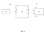
- Figure 3 shows a first embodiment of the present invention.
- sensors such as fluorescence oxygen sensors, produce an output that represents a measure of the characteristic that they are sensing.
- this output may be, in some embodiments, between 0 and 10 volts. In other embodiments, this output is between 4 and 20 mA.
- the specific output range and type is not important; other output ranges are within the scope of the invention.
- Sensor 200 is such a sensor, having an exemplary output of 0 to 10V.
- This sensor 200 is to be connected to device 210.
- the device 210 provides a polarization voltage of between 600 and 800 mV between its two leads 211,212.
- the output of the sensor is expected as a current between the two leads. In some embodiments, this current is between 0 and 100 nA.
- an interface module 220 is placed between the two components.
- This interface module 220 has an input port 222, adapted to receive signals conforming to a first specification from the sensor 200, and has an output port 221, adapted to generate outputs conforming to a second specification to the device 210.
- the first specification is 0-10 volts.
- the first specification is 4-20 mA.
- the second specification in one embodiment, is 0-100 nA between lead 211 and 212, with a polarizing voltage of 600 to 800 mV.
- the system shown in Figure 3 can be used with a fluorescence oxygen sensor, and a legacy controller, such as from Applikon.
- a disposable pharmaceutical system can be used.
- Such a system may include disposable storage bags, reaction bags and filtering devices.
- fluorescence oxygen sensors As these are less expensive than traditional polarographic sensors.
- disposable systems much like traditional systems, need to be monitored and controlled.
- the inability of an existing legacy controller to operate with a fluorescence sensor thwarts the adoption of this configuration.
- the disclosed system, and specifically the inclusion of the interface module 220 enables such a disposable configuration.
- a traditional bioreactor can be fitted with fluorescence oxygen sensors. These sensors require less maintenance, less calibration and are more accurate than polarographic sensors. Therefore, they may be more desirable in reactions requiring precision control.
- the introduction of the interface module 220 allows a legacy controller 210 to be used with this bioreactor.
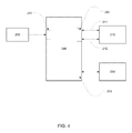
- Figure 4 shows a second embodiment of the present invention.
- This embodiment includes the sensor 200 and device 210. However, in this embodiment, a second device 230 is introduced.
- this second device 230 is adapted to receive signals conforming to the second specification. In other words, it can interface directly to the sensor 200.
- the interface module 240 contains an input port 241, adapted to receive signals from the sensor 200.
- the interface module also includes the circuitry required to convert these signals from the first specification to the second specification for the first device 210. This modified output is available on port 242.
- the interface module 240 also includes a second output port 243 to which the second device 230 can attach. This second output port 243 simply passes the signals received at input port 241 from the sensor 200 to the second device 230.
- the interface module may buffer this signal to reduce noise or load.
- One exemplary configuration may include a data logger functioning as the second device 230. This data logger may be able to accept a signal having an output between 0 and 10 V. In such a scenario, it is attached to the second port 243 on the interface module 221.
- this second device 230 is also a legacy device, and can only receive signals conforming to the first specification.
- the interface module 221 contains duplicate circuitry to produce two identical outputs on output ports 242, 243 for the two devices 210, 230.
- One exemplary configuration may include a legacy data logger, which can only accept inputs from 0-100 nA.
- this second device 230 requires inputs conforming to a third specification.
- the interface module 240 may include circuit to convert input signals received on input port 241 to output signals of a third specification on output port 243.
- the interface module 260 has a plurality of output ports, where one or more output ports 261a,b conform to the first specification, and one or more output ports 262 a,b conform to the second specification.
- Figure 4 shows two legacy controllers 210a,b and two other devices that conform to the second specification 270a,b.
- the number of each type of device is not limited, and all configurations of devices are within the scope of the invention.
- Figure 6 shows a schematic of a representative circuit used to convert signals from a first specification to a second specification.
- signals received by the interface module are in the range of 0-10 V, and the outputs must be between 0-100 nA (with a 600-800 mV polarizing voltage).
- the power supplies for the circuit are created, using traditional components and circuitry.
- the power for the interface module can be supplied either by a battery 600 or a remote power supply (not shown).
- the selection of the power source is performed using traditional methods, such as jumper 601.
- the remote power source is at a voltage greater than required.
- a voltage regulator 602 may be used to convert the incoming voltage to a lower level.
- the interim voltage 603 is used to create the power rails.
- a linear regulator 604 is used to create a smooth output voltage 605.
- a switching regulator 606 is used to create a negative rail voltage 607.
- Other methods of creating the necessary voltages for the interface module are well known and are within the scope of the disclosure.
- a connector 610 is used to connect the output of the sensor to the interface module.
- the output of the sensor is a voltage, in the range from 0-10 volts.
- a resistor divider 611 may used to reduce the voltage such that it is less than the voltage rail 605.
- an op amp 612 is used to buffer the incoming signal so as to minimize the current load thereon.
- the output of the sensor may be a current in the range from 4-20 mA, although other ranges are also possible and within the scope of the invention.
- a resistor, or resistor divider network may be used to convert this current output to a voltage.
- a programmable microprocessor having an analog to digital (A/D) converter, and a pulse width modulated (PWM) output is used. In other embodiments, other forms of D/A conversion can be employed.
- the microprocessor may also have a storage element for storing code, tables or software to be executed.
- the microprocessor may also have RAM, which can be rewritten to serve as temporary storage.
- the buffered input signal 613 is connected to the internal A/D converter of programmable microprocessor 615.
- the microprocessor 615 converts this analog voltage to a digital value, representative of the received analog voltage. Once this is completed, the microprocessor then determines a suitable output voltage.
- This determination can be based on an algorithm, which uses the incoming digital value in an equation to generate the output voltage. Such a method is useful when the output voltage has a linear or nearly linear relationship to the input voltage. In other scenarios, it may be advantageous to use a translation table to determine the appropriate output voltage. In other words, the incoming digital value is used to index a table, which provides the suggested output voltage.
- a circuit comprising passive and active components, such as resistors, capacitors, and opamps, can be employed.
- the output voltage produced by the microprocessor may be a PWM signal. In such a case, it may be necessary to convert this signal back to an analog value.
- a low pass filter 617 may be used to convert a PWM signal to an analog voltage 618.
- An opamp 619 is then used to buffer this analog voltage 618.
- the microprocessor may include a D/A converter and directly output an analog value.
- the output specification is 0-100 nA, with a 600-800 mV polarizing voltage. Therefore, the final stage of the circuit must convert an analog voltage, which is indicative of the desired current, into a current in the proper range.
- the current is determined by measuring the voltage across resistor 634, which will be between 0 mV (no current) and the full polarizing voltage of 600-800mV (maximum current).
- Opamp 632 simply buffers the voltage across resistor 634, and a resistor divider 633 may be used to reduce the voltage (if necessary) before it feeds into the negative input of opamp 630.
- a circuit having a gain greater than one is used to amplify the voltage measured across resistor 634 such that the entire voltage range of the opamp 630 can be exploited. Such an embodiment may also increase the precision of the output.
- the positive input of opamp 630 is fed by resistor divider 620.
- the output of opamp 630 is used to drive the gate of a FET transistor 631.
- This FET 631 has a variable resistance across its other two terminals, where that resistance is determined by the voltage applied to the gate of FET 631. The greater the voltage applied to the FET, the lower the resistance across its other two terminals.
- the desired voltage, as applied to the positive terminal of opamp 630 is greater than the measured voltage, as applied to the negative terminal of opamp 630, the output of opamp 630 will increase, thereby lowering the resistance of FET 631.
- the current flow through resistor 634 increases.
- circuit of Figure 6 other variations are possible. For example, if two output ports are desired, where both conform to the second specification, components 630-634 can be replicated to create a second output port. If an output port conforming to the first specification is desired, an opamp, configured as a buffer may be added near the input 610. Furthermore, if an output conforming to a third specification is desired, the applicable parts of the circuit shown in Figure 6 can be duplicated. In certain embodiments, it may be necessary to replicate the microprocessor 615. However, the code executed by the microprocessor, or the lookup tables contained within may be modified.
Landscapes
- Health & Medical Sciences (AREA)
- Nuclear Medicine, Radiotherapy & Molecular Imaging (AREA)
- Physics & Mathematics (AREA)
- Life Sciences & Earth Sciences (AREA)
- Chemical & Material Sciences (AREA)
- Analytical Chemistry (AREA)
- Biochemistry (AREA)
- General Health & Medical Sciences (AREA)
- General Physics & Mathematics (AREA)
- Immunology (AREA)
- Pathology (AREA)
- Investigating, Analyzing Materials By Fluorescence Or Luminescence (AREA)
Abstract
Description
- This application claims priority of
U.S. Provisional Patent Application No. 61/169,415, filed April 15, 2009 - Many industries, such as the pharmaceutical industry, employ sensing devices to monitor the progress or outcome of a particular event. Often, these sensing devices are used to provide input to a controller, which then varies its output, based on this input. The output of the controller is typically used to influence, affect or control the particular event.
- For example, in a bioreaction, it may be important to monitor and control a number of characteristics of the reaction, including but not limited to temperature, pH, oxygen concentration, or other parameters. Because of this, devices have been developed to sensor these characteristics. There exists a plethora of pH sensors, dissolved oxygen sensors and temperature sensors.
- However, while sensing the characteristic is important, it is equally important to be able to monitor and track these characteristics over time. Additionally, it is important to use these characteristics to determine future actions. For example,
Figure 1 shows a simple example of a closed loop control system which can be used with a bioreactor. In this figure, atemperature sensor 10 may be used to monitor the temperature of a particular reaction occurring within areaction chamber 20. Based on the output of thetemperature sensor 10, acontroller 30, in communication with thatsensor 10, may vary the output of aheating element 40. In this way, if the temperature within the reaction chamber must be within a prescribed temperature range, thecontroller 30 can use thesensor 10 and theheating element 40, in conjunction with a software control loop, to insure that these conditions are met. - Additionally, the
sensor 10 may be in communication with other devices. For example, the output of a pH sensor may be in communication with controller, a logging device and/or data storage device. The attached device samples the output of the specific sensor over time. This sampling step may be performed periodically, such as at fixed time intervals. In other embodiments, this sampling step is performed at sporadic intervals, or based on other external events. - In the case of a data logger, the value sampled is simply stored, usually with an associated timestamp, so that a graph of that characteristic over a period of time can be generated. In the case of the controller, the value is sampled so that corrective action can be performed. For example, as described above, in the case of a temperature sensor, the controller may be in communication with a heating element, such that if the temperature reading is below a predetermined threshold, the controller actuates the heating element. Similar actions can be taken in response to pH or dissolved oxygen readings.
- One of the most common dissolved oxygen sensor is known as a polarographic sensor. A representative sensor is shown in
Figure 2 . Thesensor 100 includes amembrane 120 through which oxygen can pass. It also includes acathode 130 and ananode 160. In some embodiments, thecathode 130 is made from a conductive material, such as platinum. In some embodiments, theanode 160 is made from a conductive material, such as gold or silver. These two conductive components are separated by aninsulator 140, such as glass. An external device provides a voltage potential, such as between 600 and 800 mV, between thecathode 130 and theanode 160. - In operation, oxygen molecules diffuse through the
membrane 120. These molecules are reduced at the surface of thecathode 130, such as according to the following equation:
O2 + 2H2O + 4e- → 4 OH-
At the anode, an oxidation reaction is occurring, thereby producing electrons. These electrons move toward thecathode 130, thereby generating a current proportional to the oxygen concentration. This current can then be measured by a device, such as a controller or a logging device. - Because of the popularity of polarographic sensors, many devices, such as controllers, including those made by Applikon, were designed to interface directly to them. In other words, these devices, provided a polarizing voltage of 600-800 mV, and were designed to measure the resulting current flow, which is in the range of 0-100 nA. These devices also were used to control operations, such as bioreactions, and have been used for a significant amount of time. Thus, there exists a large installed base of these controllers and other devices, configured to interoperate with polarographic sensors.
- More recently, alternative sensors have been developed. Unlike traditional polarographic sensors, these alternative sensors typically use a different indicator of oxygen content. One such indicator is fluorescence. In one embodiment, the sensor has an emitter, which emits light, typically at a specific wavelength, such as 475 nm. The light is directed toward a sensing element. The sensing element has a thin layer of hydrophobic material. A compound capable to fluorescing, such as ruthenium, is trapped within the hydrophobic material, effectively shielded from the water. The light excites the ruthenium, which then emits energy at a specific wavelength, such as 600 nm.
- Oxygen is able to effectively quench the fluorescence of ruthenium. Collision of an oxygen molecule with a fluorophore in its excited state leads to a non-radiative transfer of energy. Thus, the more collisions that occur, the less fluorescence is created. The frequency of collisions is directly related to the concentration of oxygen molecules. Therefore, the measured fluorescence is a direct measure of the concentration of oxygen molecules.
- These sensors are typically more accurate than traditional polarographic sensors. Furthermore, since they do not include any precious metals, such as platinum and silver, they are typically much less expensive. These qualities make these newer sensors the preferred choice in many applications. For example, disposable systems are more likely to utilize fluorescence oxygen sensors, due to the lower cost (especially when taking into account that the sensor will be discarded with the bag).
- However, today, it is not possible to use these new sensors with existing systems. Unlike polarographic sensors, this optical-based sensors do not require a polarizing voltage input. Furthermore, rather than producing a very small current, the output of an optical-based oxygen sensor is typically between 0 and 10 volts. In another embodiment, the output is typically between 4 and 20 mA. These outputs are completely incompatible with the input characteristics of existing devices, such as Applikon controllers. Therefore, the adoption of these new optical-based sensors has been slowed.
- Therefore, it would be beneficial if there were a system and method whereby these new, inexpensive, accurate oxygen sensors can be employed with existing devices, such as data loggers and controllers. Furthermore, it would be advantageous if these sensors were compatible with both older legacy controllers, and newer devices, such that two devices, such as a data logger and a controller, can be used simultaneously.
- The problems of the prior art are alleviated by the system and method disclosed herein. An interface module is used in combination with a newer sensor, such as a fluorescence oxygen sensor, and an older legacy device. The older legacy device supplies a polarizing voltage, and anticipates a measured current of between 0 and 100 nA. The newer sensor requires no polarizing voltage and delivers an output of 0-10 volts in one embodiment, and 4-20 mA in another embodiment. The interface module receives the output from the sensor, and converts it into a useable signal to the legacy device. In another embodiment, the interface module comprises a number of outputs, such that both legacy devices and newer devices can be in communication with the sensor simultaneously.
-
-
Figure 1 illustrates a simple control system; -
Figure 2 is a representative cross section of a polarographic oxygen sensor of the prior art; -
Figure 3 is a schematic drawing of first embodiment; -
Figure 4 is a schematic drawing of a second embodiment; -
Figure 5 is a schematic drawing of a third embodiment; -
Figure 6 is a schematic drawing of a representative circuit used in the present invention. - Pharmaceutical and biological processes often involve the transformation of materials into a final product, wherein the materials undergo various reactions. Often, it is imperative to monitor these reactions, and control them, using parameters such as temperature, pH, oxygen concentration, and others. To do so, sensors are incorporated into the reaction chambers, so that the sensor can obtain and transmit information related to a particular characteristic of the reaction. These reaction chambers can be of any type, including vats and disposable plastic bags.
-
Figure 3 shows a first embodiment of the present invention. As described above, sensors, such as fluorescence oxygen sensors, produce an output that represents a measure of the characteristic that they are sensing. For example, for a fluorescence oxygen sensor, this output may be, in some embodiments, between 0 and 10 volts. In other embodiments, this output is between 4 and 20 mA. However, the specific output range and type is not important; other output ranges are within the scope of the invention. -
Sensor 200 is such a sensor, having an exemplary output of 0 to 10V. Thissensor 200 is to be connected todevice 210. As described above, older legacy devices have certain expectations or specifications for the attached sensor. In some embodiments, thedevice 210 provides a polarization voltage of between 600 and 800 mV between its two leads 211,212. The output of the sensor is expected as a current between the two leads. In some embodiments, this current is between 0 and 100 nA. - Due to the difference in specifications between the
sensor 200 anddevice 210, these two components cannot be connected directly together. Therefore, aninterface module 220 is placed between the two components. Thisinterface module 220 has aninput port 222, adapted to receive signals conforming to a first specification from thesensor 200, and has anoutput port 221, adapted to generate outputs conforming to a second specification to thedevice 210. In one embodiment, the first specification is 0-10 volts. In a second embodiment, the first specification is 4-20 mA. The second specification, in one embodiment, is 0-100 nA betweenlead - The system shown in
Figure 3 can be used with a fluorescence oxygen sensor, and a legacy controller, such as from Applikon. This system enables a variety of new configurations. In one embodiment, a disposable pharmaceutical system can be used. Such a system may include disposable storage bags, reaction bags and filtering devices. To reduce total product cost, it is advantageous to use fluorescence oxygen sensors, as these are less expensive than traditional polarographic sensors. However, disposable systems, much like traditional systems, need to be monitored and controlled. The inability of an existing legacy controller to operate with a fluorescence sensor thwarts the adoption of this configuration. However, the disclosed system, and specifically the inclusion of theinterface module 220, enables such a disposable configuration. - In another embodiment, a traditional bioreactor can be fitted with fluorescence oxygen sensors. These sensors require less maintenance, less calibration and are more accurate than polarographic sensors. Therefore, they may be more desirable in reactions requiring precision control. The introduction of the
interface module 220 allows alegacy controller 210 to be used with this bioreactor. -
Figure 4 shows a second embodiment of the present invention. This embodiment includes thesensor 200 anddevice 210. However, in this embodiment, asecond device 230 is introduced. - In some embodiments, this
second device 230 is adapted to receive signals conforming to the second specification. In other words, it can interface directly to thesensor 200. In this embodiment, theinterface module 240 contains aninput port 241, adapted to receive signals from thesensor 200. The interface module also includes the circuitry required to convert these signals from the first specification to the second specification for thefirst device 210. This modified output is available onport 242. Theinterface module 240 also includes asecond output port 243 to which thesecond device 230 can attach. Thissecond output port 243 simply passes the signals received atinput port 241 from thesensor 200 to thesecond device 230. In some embodiments, the interface module may buffer this signal to reduce noise or load. One exemplary configuration may include a data logger functioning as thesecond device 230. This data logger may be able to accept a signal having an output between 0 and 10 V. In such a scenario, it is attached to thesecond port 243 on theinterface module 221. - In other embodiments, this
second device 230 is also a legacy device, and can only receive signals conforming to the first specification. In this embodiment, theinterface module 221 contains duplicate circuitry to produce two identical outputs onoutput ports devices - In yet other embodiments, this
second device 230 requires inputs conforming to a third specification. In this scenario, theinterface module 240 may include circuit to convert input signals received oninput port 241 to output signals of a third specification onoutput port 243. - In a third embodiment, shown in
Figure 5 , theinterface module 260 has a plurality of output ports, where one ormore output ports 261a,b conform to the first specification, and one ormore output ports 262 a,b conform to the second specification.Figure 4 shows twolegacy controllers 210a,b and two other devices that conform to thesecond specification 270a,b. However, the number of each type of device is not limited, and all configurations of devices are within the scope of the invention. -
Figure 6 shows a schematic of a representative circuit used to convert signals from a first specification to a second specification. In this embodiment, signals received by the interface module are in the range of 0-10 V, and the outputs must be between 0-100 nA (with a 600-800 mV polarizing voltage). - Referring to the upper portion of the Figure, the power supplies for the circuit are created, using traditional components and circuitry. The power for the interface module can be supplied either by a
battery 600 or a remote power supply (not shown). The selection of the power source is performed using traditional methods, such asjumper 601. In some embodiments, the remote power source is at a voltage greater than required. In such a scenario, avoltage regulator 602 may be used to convert the incoming voltage to a lower level. Theinterim voltage 603 is used to create the power rails. In some embodiments, alinear regulator 604 is used to create asmooth output voltage 605. In some embodiments, aswitching regulator 606 is used to create anegative rail voltage 607. Other methods of creating the necessary voltages for the interface module are well known and are within the scope of the disclosure. - A
connector 610 is used to connect the output of the sensor to the interface module. In some embodiments, the output of the sensor is a voltage, in the range from 0-10 volts. In such an embodiment, aresistor divider 611 may used to reduce the voltage such that it is less than thevoltage rail 605. In some embodiments, anop amp 612 is used to buffer the incoming signal so as to minimize the current load thereon. In other embodiments, the output of the sensor may be a current in the range from 4-20 mA, although other ranges are also possible and within the scope of the invention. In such an embodiment, a resistor, or resistor divider network, may be used to convert this current output to a voltage. - In certain embodiments, a programmable microprocessor, having an analog to digital (A/D) converter, and a pulse width modulated (PWM) output is used. In other embodiments, other forms of D/A conversion can be employed. The microprocessor may also have a storage element for storing code, tables or software to be executed. The microprocessor may also have RAM, which can be rewritten to serve as temporary storage. In the embodiment shown in
Figure 6 , the buffered input signal 613 is connected to the internal A/D converter ofprogrammable microprocessor 615. Themicroprocessor 615 converts this analog voltage to a digital value, representative of the received analog voltage. Once this is completed, the microprocessor then determines a suitable output voltage. This determination can be based on an algorithm, which uses the incoming digital value in an equation to generate the output voltage. Such a method is useful when the output voltage has a linear or nearly linear relationship to the input voltage. In other scenarios, it may be advantageous to use a translation table to determine the appropriate output voltage. In other words, the incoming digital value is used to index a table, which provides the suggested output voltage. - Alternatively, in lieu of a microprocessor, especially in scenarios where the desired output voltage is proportional or linearly related to the input voltage, a circuit comprising passive and active components, such as resistors, capacitors, and opamps, can be employed.
- Returning to
Figure 6 , the output voltage produced by the microprocessor may be a PWM signal. In such a case, it may be necessary to convert this signal back to an analog value. In some embodiments, a low pass filter 617 may be used to convert a PWM signal to ananalog voltage 618. Anopamp 619 is then used to buffer thisanalog voltage 618. In other embodiments, the microprocessor may include a D/A converter and directly output an analog value. - As described above, in some embodiments, the output specification is 0-100 nA, with a 600-800 mV polarizing voltage. Therefore, the final stage of the circuit must convert an analog voltage, which is indicative of the desired current, into a current in the proper range. In this embodiment, the current is determined by measuring the voltage across
resistor 634, which will be between 0 mV (no current) and the full polarizing voltage of 600-800mV (maximum current).Opamp 632 simply buffers the voltage acrossresistor 634, and aresistor divider 633 may be used to reduce the voltage (if necessary) before it feeds into the negative input ofopamp 630. In some embodiments, a circuit having a gain greater than one is used to amplify the voltage measured acrossresistor 634 such that the entire voltage range of theopamp 630 can be exploited. Such an embodiment may also increase the precision of the output. - The positive input of
opamp 630 is fed byresistor divider 620. The output ofopamp 630 is used to drive the gate of aFET transistor 631. ThisFET 631 has a variable resistance across its other two terminals, where that resistance is determined by the voltage applied to the gate ofFET 631. The greater the voltage applied to the FET, the lower the resistance across its other two terminals. Thus, if the desired voltage, as applied to the positive terminal ofopamp 630 is greater than the measured voltage, as applied to the negative terminal ofopamp 630, the output ofopamp 630 will increase, thereby lowering the resistance ofFET 631. By reducing the resistance acrossFET 631, the current flow throughresistor 634 increases. - As suggested above, other embodiments are also possible, including ones that do not include a microprocessor.
- Furthermore, other variations of the circuit of
Figure 6 are possible. For example, if two output ports are desired, where both conform to the second specification, components 630-634 can be replicated to create a second output port. If an output port conforming to the first specification is desired, an opamp, configured as a buffer may be added near theinput 610. Furthermore, if an output conforming to a third specification is desired, the applicable parts of the circuit shown inFigure 6 can be duplicated. In certain embodiments, it may be necessary to replicate themicroprocessor 615. However, the code executed by the microprocessor, or the lookup tables contained within may be modified. - While the above description illustrates a pharmaceutical system, the invention is not so limited. Other systems, such as those reactions using enzymes, nutriceuticals and pure chemical systems, can also utilize the present invention.
- The terms and expressions which have been employed herein are used as terms of description and not of limitation, and there is no intention in the use of such terms and expressions of excluding any equivalents of the features shown and described (or portions thereof). It is also recognized that various modifications are possible within the scope of the claims. Other modifications, variations, and alternatives are also possible. Accordingly, the foregoing description is by way of example only and is not intended as limiting.
Claims (15)
- A system having one or more sensors for measuring one or more parameters, comprising:a. a sensor adapted to measure a characteristic of a reaction, and transmit information about said characteristic in conformance with a first specification;b. a device adapted to receive information corresponding to a characteristic of said reaction; said information in conformance with a second specification; andc. an interface module, in communication with said sensor and said device, wherein said interface module receives information from said sensor in conformance within said first specification via an input port, converts said information to said second specification and transmits information in conformance with said second specification to said device via a first output port.
- The system of claim 1, wherein said sensor comprises a dissolved oxygen sensor.
- The system of claim 2, wherein said sensor comprises a fluorescence oxygen sensor.
- The system of claim 2, wherein said first specification comprises a voltage output in the range of 0 to 10 volts.
- The system of claim 2, wherein said first specification comprises a current output in the range of 4 to 20 milliamps.
- The system of claim 1, wherein said device comprises a controller.
- The system of claim 1, wherein said device comprises a data logger.
- The system of claim 6, wherein said second specification comprises two leads, having a polarizing voltage of 600 to 800 mV between said leads, and a current output in the range of 0 to 100 nA.
- The system of claim 1, wherein said interface module further comprisesa. a second output port on which said interface module transmits information in conformance to said first specification,b. a second output port on which said interface module transmits information in conformance to said second specification, and/orc. a second output port on which said interface module transmits information in conformance to a third specification.
- A method of utilizing a legacy controller with an oxygen sensor to control a reaction, comprising:a. locating said oxygen sensor in a reaction chamber;b. attaching the output of said oxygen sensor to an interface module;c. using said oxygen sensor to monitor said reaction;d. providing a circuit on said interface module, adapted to receive signals conforming to a first specification defined by said oxygen sensor, and output signals conforming to a second specification defined by said legacy controller;e. attaching the output of said interface module to said legacy controller; andf. utilizing said legacy controller to control said reaction.
- The method of claim 10, wherein said first specification comprises a voltage output in the range of 0 to 10 volts.
- The method of claim 10, wherein said first specification comprises a current output in the range of 4 to 20 milliamps.
- The method of claim 10, wherein said oxygen sensor comprises a fluorescence oxygen sensor.
- The method of claim 10, wherein said second specification comprises two leads, having a polarizing voltage of 600 to 800 mV between said leads, and a current output in the range of 0 to 100 nA.
- The method of claim 10, wherein said interface module further comprisesa. a second output port, wherein said method further comprises using said interface module to transmit on this second output port information in conformance to said first specification,b. a second output port, wherein said method further comprises using said interface module to transmit on this second output port information in conformance to said second specification, and/orc. a second output port, wherein said method further comprises using said interface module to transmit on this second output port information in conformance to a third specification.
Applications Claiming Priority (1)
| Application Number | Priority Date | Filing Date | Title |
|---|---|---|---|
| US16941509P | 2009-04-15 | 2009-04-15 |
Publications (2)
| Publication Number | Publication Date |
|---|---|
| EP2241881A2 true EP2241881A2 (en) | 2010-10-20 |
| EP2241881A3 EP2241881A3 (en) | 2011-07-27 |
Family
ID=42372298
Family Applications (1)
| Application Number | Title | Priority Date | Filing Date |
|---|---|---|---|
| EP10158880A Withdrawn EP2241881A3 (en) | 2009-04-15 | 2010-03-31 | Converter for use with Sensing Devices |
Country Status (5)
| Country | Link |
|---|---|
| US (2) | US8852414B2 (en) |
| EP (1) | EP2241881A3 (en) |
| JP (1) | JP5345971B2 (en) |
| CN (1) | CN101936755A (en) |
| SG (1) | SG166050A1 (en) |
Families Citing this family (1)
| Publication number | Priority date | Publication date | Assignee | Title |
|---|---|---|---|---|
| US8852414B2 (en) | 2009-04-15 | 2014-10-07 | Emd Millipore Corporation | Converter for use with sensing devices |
Family Cites Families (27)
| Publication number | Priority date | Publication date | Assignee | Title |
|---|---|---|---|---|
| DE3637304A1 (en) * | 1986-08-23 | 1988-05-05 | Vdo Schindling | METHOD AND CIRCUIT FOR DETECTING THE READY FOR OPERATION OF AN OXYGEN MEASUREMENT PROBE |
| NL9100984A (en) | 1991-06-07 | 1993-01-04 | Applikon Dependable Instr Bv | METHOD FOR DETERMINING THE CONCENTRATION OF A SUBSTANTIAL TO BE DETERMINED USING AN ION-SELECTIVE ELECTRODE AND USING AN APPARATUS IN THIS METHOD |
| JP3115408B2 (en) | 1992-05-28 | 2000-12-04 | 能美防災株式会社 | Fire alarm system |
| US5344544A (en) | 1992-07-06 | 1994-09-06 | Porton Diagnostics, Inc. | Diagnostic electrode for evaluating circuitry of an analyzer |
| US5326447A (en) * | 1992-09-30 | 1994-07-05 | The Foxboro Company | Oxygen analyzer |
| US5669009A (en) | 1994-06-30 | 1997-09-16 | Hughes Electronics | Signal processing array |
| JPH08287346A (en) | 1995-04-11 | 1996-11-01 | Kubota Corp | Communication interface device for vending machines |
| GB9514528D0 (en) | 1995-07-15 | 1995-09-13 | Smiths Industries Plc | Electrical apparatus |
| US5708368A (en) | 1996-03-07 | 1998-01-13 | Ade Corporation | Method and apparatus for emulation of a linear variable differential transducer by a capacitive gaging system |
| JPH09282271A (en) | 1996-04-17 | 1997-10-31 | Canon Inc | Communication device and control method thereof |
| US5735605A (en) | 1996-10-02 | 1998-04-07 | Deroyal Industries, Inc. | Thermocouple temperature probe adapter |
| US5793230A (en) | 1997-02-26 | 1998-08-11 | Sandia Corporation | Sensor readout detector circuit |
| DE19846461B4 (en) * | 1997-10-08 | 2006-05-11 | Hitachi, Ltd. | Sensoreinstellschaltung |
| EP0965980A1 (en) | 1998-06-19 | 1999-12-22 | Deutsche Thomson-Brandt Gmbh | Device for amplifying and converting current signals into voltage signals |
| DE10025578C2 (en) | 2000-05-24 | 2002-03-21 | Siemens Ag | Test and calibration device for an evaluation circuit of a linear oxygen probe (lambda probe) |
| WO2003008957A1 (en) | 2000-12-07 | 2003-01-30 | Aep Emtech, Llc | COMBINED OXYGEN AND NOx SENSOR |
| US6632402B2 (en) | 2001-01-24 | 2003-10-14 | Ntc Technology Inc. | Oxygen monitoring apparatus |
| JP4535741B2 (en) * | 2003-01-30 | 2010-09-01 | 株式会社タニタ | Measuring method using chemical sensor and chemical sensor type measuring device |
| EP1445678A1 (en) | 2003-02-05 | 2004-08-11 | Agilent Technologies, Inc. - a Delaware corporation - | Voltage to current converter |
| US7340543B2 (en) * | 2003-09-24 | 2008-03-04 | Lockheed Martin Corporation | Device and method for discrete signal conditioning |
| JP2005252810A (en) | 2004-03-05 | 2005-09-15 | Canon Inc | Current-voltage conversion circuit |
| US7135841B1 (en) | 2004-11-10 | 2006-11-14 | National Semiconductor Corporation | Emulated inductor current automatic correction without knowledge of actual inductor current ramp for emulated peak control mode PWM |
| US7433267B2 (en) | 2004-12-13 | 2008-10-07 | Ssi Technologies, Inc. | Two wire resistive sensor |
| JP4358785B2 (en) | 2005-05-27 | 2009-11-04 | 麒麟麦酒株式会社 | Method for measuring oxygen content in sealed container and piercing device for sealed container used therefor |
| US7830805B2 (en) | 2005-08-12 | 2010-11-09 | The Invention Science Fund I, Llc | Sensor emulation using mote networks |
| CN100541194C (en) * | 2007-08-14 | 2009-09-16 | 浙江大学 | Water body environment pollution monitoring system based on electrochemical sensor |
| US8852414B2 (en) | 2009-04-15 | 2014-10-07 | Emd Millipore Corporation | Converter for use with sensing devices |
-
2010
- 2010-03-24 US US12/730,754 patent/US8852414B2/en not_active Expired - Fee Related
- 2010-03-30 SG SG201002180-6A patent/SG166050A1/en unknown
- 2010-03-31 EP EP10158880A patent/EP2241881A3/en not_active Withdrawn
- 2010-04-14 CN CN2010101652432A patent/CN101936755A/en active Pending
- 2010-04-15 JP JP2010094162A patent/JP5345971B2/en not_active Expired - Fee Related
-
2011
- 2011-12-22 US US13/334,592 patent/US8852421B2/en not_active Expired - Fee Related
Non-Patent Citations (2)
| Title |
|---|
| DIETMAYER ET AL: "Integrated online diagnosis for AMR-based angular measurement systems", SENSORS AND ACTUATORS A, ELSEVIER SEQUOIA S.A., LAUSANNE, CH, vol. 91, no. 1-2, 5 June 2001 (2001-06-05), pages 12 - 15, XP027357282, ISSN: 0924-4247, [retrieved on 20010605] * |
| Instruction Manual FIBOX 3-LCD 26.05.2004 (DR. Huber; Dr Krause) |
Also Published As
| Publication number | Publication date |
|---|---|
| EP2241881A3 (en) | 2011-07-27 |
| JP2011022130A (en) | 2011-02-03 |
| US20100264041A1 (en) | 2010-10-21 |
| US8852414B2 (en) | 2014-10-07 |
| JP5345971B2 (en) | 2013-11-20 |
| CN101936755A (en) | 2011-01-05 |
| US20120091012A1 (en) | 2012-04-19 |
| US8852421B2 (en) | 2014-10-07 |
| SG166050A1 (en) | 2010-11-29 |
Similar Documents
| Publication | Publication Date | Title |
|---|---|---|
| US6908535B2 (en) | Current-to-voltage-converter for a biosensor | |
| US20100066378A1 (en) | Current Mirror Potentiostat | |
| KR101462019B1 (en) | Blood glucose measuring instrument | |
| DE102016117733A1 (en) | measuring device | |
| US20180266986A1 (en) | Multichannel potentiostat analyzer system and methods | |
| US8852414B2 (en) | Converter for use with sensing devices | |
| CN1325906C (en) | Portable multifunctional electrochemical biodetector | |
| Lin et al. | A multichannel electrochemical sensor interface IC for bioreactor monitoring | |
| Nien et al. | Improving the Drift Effect and Hysteresis Effect of Urea Biosensor Based on Graphene Oxide/Nickel Oxide Sensing Film Modified Either by Au Nanoparticles or γ-Fe₂O₃ Nanoparticles Using Back-End Calibration Circuit | |
| KR20220110386A (en) | Apparatus and method for detecting sample using nanowire fet | |
| Lazaro et al. | Low-cost wireless device for DNA sensing using square wave voltammetry | |
| Chou et al. | Fabrication and characteristic analysis of a remote real-time monitoring applied to glucose sensor system based on microfluidic framework | |
| Huynh Vo et al. | P-EcStat: a versatile design of photoelectrochemical and electrochemical sensing system with smartphone interface via bluetooth low energy | |
| Pajusalu et al. | Open-source sensor for measuring oxygen partial pressures below 100 microbars | |
| Hefele et al. | Integrated multipurpose analog front-end for electrochemical ISFET sensors | |
| Kim et al. | Manipulation of microenvironment with a built-in electrochemical actuator in proximity of a dissolved oxygen microsensor | |
| US20120235739A1 (en) | Programmable gain amplifier with multi-range operation for use in body sensor interface applications | |
| López et al. | Development of Continuous Flow Analysis System Based on Amperometric Biosensors | |
| Ghoreishizadeh et al. | Sub-mW reconfigurable interface IC for electrochemical sensing | |
| Raj et al. | Fabrication of a configurable multi-potentiostat for LOC applications | |
| EP4471415A1 (en) | Electronic device configured to convert electro-optical gas sensor data into an analog signal | |
| Lai et al. | Biosensor integrated with transducer to detect the glucose | |
| Germano et al. | Microsystem for biological analysis based on magnetoresistive sensing | |
| US20070068805A1 (en) | Operating circuit for a biosensor arrangement | |
| US20250244285A1 (en) | Circuitry for Measurement of Electrochemical Cells |
Legal Events
| Date | Code | Title | Description |
|---|---|---|---|
| PUAI | Public reference made under article 153(3) epc to a published international application that has entered the european phase |
Free format text: ORIGINAL CODE: 0009012 |
|
| AK | Designated contracting states |
Kind code of ref document: A2 Designated state(s): AT BE BG CH CY CZ DE DK EE ES FI FR GB GR HR HU IE IS IT LI LT LU LV MC MK MT NL NO PL PT RO SE SI SK SM TR |
|
| AX | Request for extension of the european patent |
Extension state: AL BA ME RS |
|
| RIN1 | Information on inventor provided before grant (corrected) |
Inventor name: BAGGIO, RICKY F. Inventor name: JOENS, MICHAEL |
|
| PUAL | Search report despatched |
Free format text: ORIGINAL CODE: 0009013 |
|
| AK | Designated contracting states |
Kind code of ref document: A3 Designated state(s): AT BE BG CH CY CZ DE DK EE ES FI FR GB GR HR HU IE IS IT LI LT LU LV MC MK MT NL NO PL PT RO SE SI SK SM TR |
|
| AX | Request for extension of the european patent |
Extension state: AL BA ME RS |
|
| RIC1 | Information provided on ipc code assigned before grant |
Ipc: G01N 27/28 20060101ALI20110620BHEP Ipc: G01N 21/64 20060101ALI20110620BHEP Ipc: G01N 27/26 20060101AFI20100805BHEP |
|
| 17P | Request for examination filed |
Effective date: 20120126 |
|
| TPAC | Observations filed by third parties |
Free format text: ORIGINAL CODE: EPIDOSNTIPA |
|
| RAP1 | Party data changed (applicant data changed or rights of an application transferred) |
Owner name: EMD MILLIPORE CORPORATION |
|
| 17Q | First examination report despatched |
Effective date: 20120321 |
|
| STAA | Information on the status of an ep patent application or granted ep patent |
Free format text: STATUS: THE APPLICATION IS DEEMED TO BE WITHDRAWN |
|
| 18D | Application deemed to be withdrawn |
Effective date: 20161001 |