EP2241831A1 - Air conditioner with reduced standby power consuption of the outdoor unit on the basis of a three wire cable connection between indoor and outdoor unit - Google Patents
Air conditioner with reduced standby power consuption of the outdoor unit on the basis of a three wire cable connection between indoor and outdoor unit Download PDFInfo
- Publication number
- EP2241831A1 EP2241831A1 EP10002461A EP10002461A EP2241831A1 EP 2241831 A1 EP2241831 A1 EP 2241831A1 EP 10002461 A EP10002461 A EP 10002461A EP 10002461 A EP10002461 A EP 10002461A EP 2241831 A1 EP2241831 A1 EP 2241831A1
- Authority
- EP
- European Patent Office
- Prior art keywords
- outdoor
- unit
- indoor
- power
- relay
- Prior art date
- Legal status (The legal status is an assumption and is not a legal conclusion. Google has not performed a legal analysis and makes no representation as to the accuracy of the status listed.)
- Granted
Links
Images


Classifications
-
- F—MECHANICAL ENGINEERING; LIGHTING; HEATING; WEAPONS; BLASTING
- F24—HEATING; RANGES; VENTILATING
- F24F—AIR-CONDITIONING; AIR-HUMIDIFICATION; VENTILATION; USE OF AIR CURRENTS FOR SCREENING
- F24F1/00—Room units for air-conditioning, e.g. separate or self-contained units or units receiving primary air from a central station
- F24F1/0003—Room units for air-conditioning, e.g. separate or self-contained units or units receiving primary air from a central station characterised by a split arrangement, wherein parts of the air-conditioning system, e.g. evaporator and condenser, are in separately located units
-
- F—MECHANICAL ENGINEERING; LIGHTING; HEATING; WEAPONS; BLASTING
- F24—HEATING; RANGES; VENTILATING
- F24F—AIR-CONDITIONING; AIR-HUMIDIFICATION; VENTILATION; USE OF AIR CURRENTS FOR SCREENING
- F24F11/00—Control or safety arrangements
- F24F11/50—Control or safety arrangements characterised by user interfaces or communication
- F24F11/52—Indication arrangements, e.g. displays
-
- F—MECHANICAL ENGINEERING; LIGHTING; HEATING; WEAPONS; BLASTING
- F24—HEATING; RANGES; VENTILATING
- F24F—AIR-CONDITIONING; AIR-HUMIDIFICATION; VENTILATION; USE OF AIR CURRENTS FOR SCREENING
- F24F1/00—Room units for air-conditioning, e.g. separate or self-contained units or units receiving primary air from a central station
- F24F1/06—Separate outdoor units, e.g. outdoor unit to be linked to a separate room comprising a compressor and a heat exchanger
- F24F1/26—Refrigerant piping
- F24F1/32—Refrigerant piping for connecting the separate outdoor units to indoor units
-
- F—MECHANICAL ENGINEERING; LIGHTING; HEATING; WEAPONS; BLASTING
- F24—HEATING; RANGES; VENTILATING
- F24F—AIR-CONDITIONING; AIR-HUMIDIFICATION; VENTILATION; USE OF AIR CURRENTS FOR SCREENING
- F24F11/00—Control or safety arrangements
- F24F11/30—Control or safety arrangements for purposes related to the operation of the system, e.g. for safety or monitoring
-
- F—MECHANICAL ENGINEERING; LIGHTING; HEATING; WEAPONS; BLASTING
- F24—HEATING; RANGES; VENTILATING
- F24F—AIR-CONDITIONING; AIR-HUMIDIFICATION; VENTILATION; USE OF AIR CURRENTS FOR SCREENING
- F24F11/00—Control or safety arrangements
- F24F11/62—Control or safety arrangements characterised by the type of control or by internal processing, e.g. using fuzzy logic, adaptive control or estimation of values
-
- F—MECHANICAL ENGINEERING; LIGHTING; HEATING; WEAPONS; BLASTING
- F24—HEATING; RANGES; VENTILATING
- F24F—AIR-CONDITIONING; AIR-HUMIDIFICATION; VENTILATION; USE OF AIR CURRENTS FOR SCREENING
- F24F11/00—Control or safety arrangements
- F24F11/30—Control or safety arrangements for purposes related to the operation of the system, e.g. for safety or monitoring
- F24F11/46—Improving electric energy efficiency or saving
-
- F—MECHANICAL ENGINEERING; LIGHTING; HEATING; WEAPONS; BLASTING
- F24—HEATING; RANGES; VENTILATING
- F24F—AIR-CONDITIONING; AIR-HUMIDIFICATION; VENTILATION; USE OF AIR CURRENTS FOR SCREENING
- F24F11/00—Control or safety arrangements
- F24F11/62—Control or safety arrangements characterised by the type of control or by internal processing, e.g. using fuzzy logic, adaptive control or estimation of values
- F24F11/63—Electronic processing
- F24F11/65—Electronic processing for selecting an operating mode
Landscapes
- Engineering & Computer Science (AREA)
- Chemical & Material Sciences (AREA)
- Combustion & Propulsion (AREA)
- Mechanical Engineering (AREA)
- General Engineering & Computer Science (AREA)
- Human Computer Interaction (AREA)
- Physics & Mathematics (AREA)
- Fuzzy Systems (AREA)
- Mathematical Physics (AREA)
- Signal Processing (AREA)
- Air Conditioning Control Device (AREA)
Abstract
An indoor unit (2) includes an outdoor activation relay (22) configured to open and close a connection between a power line (8) and a signal line (16), and an indoor control unit (5) configured to operate the outdoor activation relay (22) and supply the utility power (7) between the signal line (16) and a power signal common line (9), and the indoor control unit (5) opens a connection between the power line (8) and the power signal common line (9) in a standby condition.
Description
- The present invention relates to an air conditioner.
- As one of the air conditioners in the related art, "an air conditioner in which power supplied to an indoor unit is supplied to an outdoor unit via power supply electric wiring, and a reference frequency extraction circuit, an indoor unit rectifier circuit, and an indoor unit control unit are provided in the indoor unit, characterized in that utility power is connected to the indoor unit rectifier circuit and the indoor unit control unit, a power relay and the reference frequency extraction circuit are connected to the power supply electric wiring for supplying power to the outdoor unit, and the reference frequency extraction circuit is brought into a non-energized state by opening the power relay in a standby condition." is proposed (For example, see Patent Literature 1).
Citation List
Patent Literature - Patent Literature 1:
JP-A-2007-225128 - In the air conditioner in the related art, communications are carried out between the indoor unit and the outdoor unit, and the outdoor unit is activated by a transmission of an operation start signal or the like to
the outdoor unit. However, since the communications are constantly carried out in the standby condition, there is a problem that power is constantly consumed by the indoor unit and the outdoor unit, so that standby condition power consumption is consumed in the standby condition. - According to the technology described in
Patent Literature 1, in a case of an outdoor power receiving system in which the utility power is supplied from the outdoor unit to the indoor unit, there is a problem that control cannot be achieved as-is without increasing the number of cores of the connecting cable between the indoor unit and the outdoor unit from three. - In order to solve the problems as described above, it is an object of the invention to provide an air conditioner in which the standby condition power consumption is reduced.
- An air conditioner according to the invention includes: an indoor unit and an outdoor unit, the indoor unit and the outdoor unit being connected by a three core cable including a power line, a common line, and a signal line to distribute utility power supplied to either one of the outdoor unit or the indoor unit via the power line and the common line,
the indoor unit includes: an outdoor activation relay configured to open and close a connection between the power line and the signal line; and an indoor control unit is configured to operate the outdoor activation relay to supply the utility power between the signal line and the common line, and
the indoor control unit opens the connection between the power line and the signal line in a standby condition. Advantageous Effects of Invention - The invention is configured to open the connection between the power line and the signal line by the outdoor activation relay in the standby condition, and no utility power is supplied between the signal line and the common line, so that reduction of the standby condition power consumption is achieved.
-
-
Fig. 1 is an electric component system block diagram of an air conditioner according toEmbodiment 1; -
Fig. 2 is an electric component system block diagram of the air conditioner according toEmbodiment 1 in a standby condition; -
Fig. 3 is an electric component system block diagram of the air conditioner according toEmbodiment 1 in a state in which an outdoor unit is activated; -
Fig. 4 is an electric component system diagram of the air conditioner according toEmbodiment 1 during operation; -
Fig. 5 is a flowchart showing an operation of an indoor unit according toEmbodiment 1; -
Fig. 6 is a flowchart showing an operation of the outdoor unit according toEmbodiment 1; -
Fig. 7 is an electric component system block diagram of an air conditioner according toEmbodiment 2; -
Fig. 8 is a flowchart showing an operation of an outdoor unit according toEmbodiment 2; -
Fig. 9 is an electric component system block diagram of an air conditioner according toEmbodiment 3; -
Fig. 10 is a flowchart showing an operation of an indoor unit according toEmbodiment 3; -
Fig. 11 is an electric component system block diagram of an air conditioner in the standby condition according toEmbodiment 4; -
Fig. 12 is an electric component system block diagram of the air conditioner according toEmbodiment 4 in which one of indoor units is activated; -
Fig. 13 is an electric component system block diagram of the air conditioner according toEmbodiment 4 in which one of the indoor units is in operation; and -
Fig. 14 is a flowchart showing an operation of an outdoor unit according to Embodiment 4. -
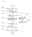
Fig. 1 is an electric component system block diagram of an air conditioner according toEmbodiment 1.
As shown inFig. 1 , anair conditioner 1 includes anindoor unit 2 and anoutdoor unit 3 in Embodiment 1.
Theindoor unit 2 includes anindoor terminal base 30. Theindoor terminal base 30 includes terminals S1, S2, and S3. Theoutdoor unit 3 includes anoutdoor terminal base 31. Theoutdoor terminal base 31 includes terminal.s L, N, S1, S2, and S3. - The
indoor unit 2 and theoutdoor unit 3 are connected by a three core cable including apower line 8, a power signalcommon line 9, and asignal line 16.
Thepower line 8 is connected to the terminal S1 on theindoor terminal base 30 and the terminal S1 on theoutdoor terminal base 31.
The power signalcommon line 9 is connected to the terminal S2 on theindoor terminal base 30 and the terminal S2 on theoutdoor terminal base 31.
Thesignal line 16 is connected to the terminal S3 on theindoor terminal base 30 and the terminal S3 on theoutdoor terminal base 31. -
Utility power 7 is connected to the terminals L and N on theoutdoor terminal base 31 of theoutdoor unit 3.
The terminal L on theoutdoor terminal base 31 is connected to the terminal S1 on theoutdoor terminal base 31.
The terminal N on theoutdoor terminal base 31 is connected to the terminal S2 on theoutdoor terminal base 31.
Accordingly, theutility power 7 supplied to the terminals L and N on theoutdoor terminal base 31 is supplied from the terminals S1 and S2 on theoutdoor terminal base 31 to the terminals S1 and S2 on theindoor terminal base 30 of theindoor unit 2 via thepower line 8 and the power signalcommon line 9. - The
indoor unit 2 includes anindoor rectifier 4, anindoor control unit 5, an indoorcommunication circuit unit 6, areceiving unit 18, anoutdoor activation relay 22, an outdoorpower supply line 24, and a power receivingsystem data unit 26. - The
indoor rectifier 4 is connected to the terminals S1 and S2 of theindoor terminal base 30. Theindoor rectifier 4 converts an AC voltage to a given DC voltage, and supplies the same to theindoor control unit 5. - The indoor
communication circuit unit 6 is connected to the terminals S2 and S3 of theindoor terminal base 30. The indoorcommunication circuit unit 6 carries out communication with an outdoor communication circuit unit 14 (described later) of theoutdoor unit 3 via thesignal line 16 and the power signalcommon line 9. - The power receiving
system data unit 26 is connected to theindoor control unit 5. The power receivingsystem data unit 26 is, for example, a storage device, and is configured to be connected and disconnected by a switching operation of a jumper cable or a switch.
The power receivingsystem data unit 26 stores information used for discriminating between an indoor power receiving system and an outdoor power receiving system.
The power receivingsystem data unit 26 also stores information used for discriminating whether or not theoutdoor unit 3 connected to theindoor unit 2 includes an outdoor relay 11 (described later) and an inrush current preventing relay 19 (described later) and allows reduction of power consumption in a standby condition (hereinafter, referred to as "standby condition power consumption reduction capability information"). - The
receiving unit 18 is connected to theindoor control unit 5. Thereceiving unit 18 receives signals from aremote controller 17 and transmits the signals to theindoor control unit 5. - The
indoor control unit 5 operates theoutdoor activation relay 22. Theindoor control unit 5 also operates the indoorcommunication circuit unit 6 to perform transmission and reception of a variety of operation signals with respect to theoutdoor unit 3. - The outdoor
power supply line 24 is connected at one end thereof to the terminal S1 on theindoor terminal base 30 and at the other end thereof to theoutdoor activation relay 22. - The
outdoor activation relay 22 is configured to switch the connection from a connection between the terminal S3 on theindoor terminal base 30 and the indoorcommunication circuit unit 6 to a connection between the terminal S3 on theindoor terminal base 30 and the outdoorpower supply line 24, or vice versa.
In other words, theoutdoor activation relay 22 opens and closes the connection between thepower line 8 and thesignal line 16. When theoutdoor activation relay 22 is operated, theutility power 7 is supplied between thesignal line 16 and the power signalcommon line 9.
Theoutdoor activation relay 22 connects the terminal S3 on theindoor terminal base 30 and the indoorcommunication circuit unit 6 in a stationary state and, when the operation is effected by theindoor control unit 5, opens the connection between the terminal S3 on theindoor terminal base 30 and the indoorcommunication circuit unit 6, and connects the terminal S3 on theindoor terminal base 30 to the outdoorpower supply line 24. - Although not shown, the
indoor unit 2 is provided with an indoor heat exchanger, an indoor fan, a sensor, a display as mechanical systems. - The
outdoor unit 3 includes an inrushcurrent preventing resistance 10, theoutdoor relay 11, anoutdoor rectifier 12, a communication circuitpower supply unit 13, the outdoorcommunication circuit unit 14, anoutdoor control unit 15, the inrushcurrent preventing relay 19, an inrush current preventingrelay coil 20, a powersupply cutoff relay 21, aninverter circuit 23, and acapacitor 25. - The
outdoor relay 11 is connected to at one end thereof to the terminal L on theoutdoor terminal base 31 and at the other end thereof to theoutdoor rectifier 12.
In the stationary state, theoutdoor relay 11 opens a contact point (normally open) and, when the operation is effected by theoutdoor control unit 15, closes the contact point (hereinafter, also referred to as "short circuit"). - The inrush
current preventing resistance 10 is provided in parallel with theoutdoor relay 11. The inrushcurrent preventing resistance 10 is connected at one end thereof to the terminal L of theoutdoor terminal base 31 via the inrushcurrent preventing relay 19 and at the other end thereof to theoutdoor rectifier 12.
The inrushcurrent preventing resistance 10 is configured to restrain an inrush current to thecapacitor 25. - The inrush
current preventing relay 19 is provided in parallel with theoutdoor relay 11. The inrushcurrent preventing relay 19 is connected at one end thereof to the terminal L of theoutdoor terminal base 31 and at the other end thereof to the inrushcurrent preventing resistance 10.
In a stationary state, the inrushcurrent preventing relay 19 opens the contact point (normally open) and, when the inrush current preventingrelay coil 20 is energized, closes the contact point to make a short circuit between the inrush current preventingresistance 10 and the terminal L of theoutdoor terminal base 31.
In other words, the inrush current preventingrelay coil 20 closes the inrushcurrent preventing relay 19 when theutility power 7 is supplied between thesignal line 16 and the power signalcommon line 9. - The
outdoor rectifier 12 is connected to the terminal L on theoutdoor terminal base 31 via theoutdoor relay 11 and the inrushcurrent preventing resistance 10. Theoutdoor rectifier 12 is also connected to the terminal N on theoutdoor terminal base 31.
Theoutdoor rectifier 12 converts an AC voltage supplied from theutility power 7 to a given DC voltage, and supplies the same to theoutdoor control unit 15 and theinverter circuit 23. - The
capacitor 25 is provided between outputs of theoutdoor rectifier 12 for smoothing an output from theoutdoor rectifier 12 and supplying a DC voltage to theinverter circuit 23. - The
inverter circuit 23 converts the input DC voltage to an AC voltage of a given frequency and a given voltage. Theinverter circuit 23 is provided with a motor or the like connected thereto, and drives a compressor or the like provided in theoutdoor unit 3. - The
outdoor control unit 15 operates theoutdoor relay 11 and the powersupply cutoff relay 21. Theoutdoor control unit 15 also operates the outdoorcommunication circuit unit 14 to perform transmission and reception of a variety of operation signals with respect to theindoor unit 2.
Theoutdoor control unit 15 controls theinverter circuit 23. - The communication circuit
power supply unit 13 is connected at one end thereof to a point between theoutdoor relay 11 and theoutdoor rectifier 12, thereby being connected to the terminal L on theoutdoor terminal base 31 via theoutdoor relay 11 and the inrushcurrent preventing relay 19, and at the other end thereof to the terminal S2 on theoutdoor terminal base 31.
The communication circuitpower supply unit 13 converts an AC voltage supplied from theutility power 7 to a given DC voltage and supplies the same to the outdoorcommunication circuit unit 14. The communication circuitpower supply unit 13 is made up of, for example, a half-wave rectifier circuit. - The outdoor
communication circuit unit 14 is connected at one end thereof to the terminal S3 on theoutdoor terminal base 31 and at the other end thereof to the communication circuitpower supply unit 13. The outdoorcommunication circuit unit 14 carries out communications with the indoorcommunication circuit unit 6 of theindoor unit 2 via thesignal line 16 and the power signalcommon line 9. - The inrush current preventing
relay coil 20 is connected at one end thereof to the terminal S2 on theoutdoor terminal base 31, and at the other end thereof to the terminal S3 on theoutdoor terminal base 31 via the powersupply cutoff relay 21.
The inrush current preventingrelay coil 20 closes the contact point of the inrush current preventing relay when being energized. - The power
supply cutoff relay 21 is connected at one end thereof to the inrush current preventingrelay coil 20, and at the other end thereof to the terminal S3 on theoutdoor terminal base 31.
In the stationary state, the powersupply cutoff relay 21 closes the contact point (normally close) and, when operated by theoutdoor control unit 15, opens the contact point so that energization of the inrush current preventingrelay coil 20 is cut off. - Although not shown, the
outdoor unit 3 is provided with an outdoor heat exchange, an outdoor fan, a sensor, an electromagnetic expansion valve, a refrigerant switching valve, and a compressor as mechanical systems. - The power signal
common line 9 corresponds to a "common line" in the invention.
Theoutdoor relay 11 and the inrushcurrent preventing relay 19 each correspond to a "power supply relay" in the invention.
The inrush current preventingrelay coil 20 corresponds to a "power supply relay coil" in the invention. - The configuration of the air conditioner in
Embodiment 1 has been described. - Subsequently, an operation of the air conditioner in
Embodiment 1 will be described. - First of all, supply of power in the
air conditioner 1 in the standby condition will be described. -
Fig. 2 is an electric component system block diagram of the air conditioner in the standby condition according toEmbodiment 1. - As shown in
Fig. 2 , theutility power 7 supplied to the terminals L and N of theoutdoor terminal base 31 is supplied from the terminals S1 and S2 on theoutdoor terminal base 31 to the terminals S1 and S2 on theindoor terminal base 30 of theindoor unit 2 via thepower line 8 and the power signalcommon line 9. - Then, the
indoor rectifier 4 receives theutility power 7 supplied to the terminals S1 and S2 of theindoor terminal base 30 of theindoor unit 2. - The
indoor rectifier 4 converts the input AC voltage to a given DC voltage. Theindoor rectifier 4 supplies the converted DC voltage to respective components of theindoor control unit 5 and theindoor unit 2. - The
indoor control unit 5 determines whether theair conditioner 1 employs the indoor power receiving system or the outdoor power receiving system on the basis of data stored in the power receivingsystem data unit 26 and, when it is determined to be the outdoor power receiving system, enables the control of theoutdoor activation relay 22. - The
indoor control unit 5 determines whether or not theoutdoor unit 3 connected to theindoor unit 2 is of the type which allows reduction of power consumption in the standby condition on the basis of the standby condition power consumption reduction capability information stored in the power receivingsystem data unit 26.
InEmbodiment 1, a case where theoutdoor unit 3 is of the type which allows reduction of the power consumption in the standby condition will be described.
An operation when theoutdoor unit 3 is not of the type which allows reduction of the power consumption in the standby condition will be described in conjunction withEmbodiment 2. - The
outdoor activation relay 22 connects the terminal S3 on theindoor terminal base 30 and the indoorcommunication circuit unit 6 in the stationary state.
Accordingly, the indoorcommunication circuit unit 6 is connected to theoutdoor unit 3 via thesignal line 16, and is brought into a state of being capable of establishing communications with theoutdoor unit 3.
At the same time, theindoor control unit 5 is brought into a state of waiting for the reception of an operation start request signal transmitted from theremote controller 17 and received via the receivingunit 18. - The contact points of the
outdoor relay 11 and the inrushcurrent preventing relay 19 of theoutdoor unit 3 are opened in the stationary state.
At the same time, theoutdoor activation relay 22 of theindoor unit 2 opens the connection between the terminal S3 on theindoor terminal base 30 and the outdoorpower supply line 24.
Therefore, noutility power 7 is supplied between the terminals S2 and S3 on theoutdoor terminal base 31, so that the inrush current preventingrelay coil 20 is in a non-energized state.
Therefore, even when theutility power 7 is supplied to the terminals L and N on theoutdoor terminal base 31 of theoutdoor unit 3, the inrushcurrent preventing relay 19 and theoutdoor relay 11 are each brought into an opened state.
Therefore, in the standby condition, a power source supply to the respective components connected to downstream of the inrushcurrent preventing relay 19 and theoutdoor relay 11 is cut off, so that reduction of the power consumption of theoutdoor unit 3 in the standby condition is achieved. - Subsequently, the operation of the outdoor unit of the air conditioner at the time of activation and during operation will be described.
-
Fig. 3 is an electric component system block diagram of the air conditioner according toEmbodiment 1, showing a state where the outdoor unit of the air conditioner is activated.
Fig. 4 is an electric component system block diagram of the air conditioner according toEmbodiment 1 during operation.
Fig. 5 is a flowchart showing an operation of the indoor unit according toEmbodiment 1.
Fig. 6 is a flowchart showing an operation of the outdoor unit according toEmbodiment 1.
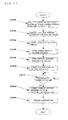
Referring now toFig. 3 andFig. 4 , description will be given on the basis of respective steps inFig. 5 andFig. 6 . - First of all, an operation of the
indoor unit 2 will be described. - The
indoor control unit 5 receives an operation start request from theremote controller 17 via the receivingunit 18. - The
indoor control unit 5 makes a reference to the information in the power receivingsystem data unit 26 and, when data from the power receivingsystem data unit 26 indicates the outdoor power receiving system, operates the indoorcommunication circuit unit 6 to start communications with theoutdoor unit 3. - The
indoor control unit 5 determines whether or not communications between the indoorcommunication circuit unit 6 and the outdoorcommunication circuit unit 14 of theoutdoor unit 3 are established. - If the communications between the indoor
communication circuit unit 6 and theoutdoor unit 3 are established, the procedure goes toStep 9. - In contrast, if the communication between the indoor
communication circuit unit 6 and theoutdoor unit 3 is not established inStep 3, theindoor control unit 5 operates (turns ON) theoutdoor activation relay 22 to open the connection between the terminal S3 of theindoor terminal base 30 and the indoorcommunication circuit unit 6, and connects the terminal S3 of theindoor terminal base 30 with the outdoorpower supply line 24.
Accordingly, theutility power 7 is supplied between thesignal line 16 and the power signalcommon line 9. - The
indoor control unit 5 operates theoutdoor activation relay 22 for a predetermined time.
The predetermined time may be set to a time (n seconds) required for charging thecapacitor 25 of theoutdoor unit 3. The predetermined time is not limited thereto. - The
indoor control unit 5 operates theoutdoor activation relay 22 for the predetermined time, then stops (turns OFF) the operation thereof, connects the terminal S3 on theindoor terminal base 30 and the indoorcommunication circuit unit 6, and opens the connection between the terminal S3 on theindoor terminal base 30 and the outdoor power supply line 24 (seeFig. 3 ). - The
indoor control unit 5 operates the indoorcommunication circuit unit 6 to start the communications with theoutdoor unit 3. - Then, the
indoor control unit 5 determines whether or not the communications between the indoorcommunication circuit unit 6 and the outdoorcommunication circuit unit 14 of theoutdoor unit 3 are established again. - When the communications between the indoor
communication circuit unit 6 and theoutdoor unit 3 are established, the indoorcommunication circuit unit 6 starts communications with the outdoorcommunication circuit unit 14 of theoutdoor unit 3. - The
indoor control unit 5 carries out communications with theoutdoor unit 3 via the indoorcommunication circuit unit 6, and causes theair conditioner 1 to perform a cooling operation or a heating operation. - In contrast, if the communications between the indoor
communication circuit unit 6 and theoutdoor unit 3 cannot be established inStep 7, theindoor control unit 5 operates the indoorcommunication circuit unit 6 again to start communications with theoutdoor unit 3.
Then, theindoor control unit 5 determines whether or not the communications between the indoorcommunication circuit unit 6 and theoutdoor unit 3 are established within the predetermined time (n seconds) . - If the communications between the indoor
communication circuit unit 6 and theoutdoor unit 3 cannot be established within n seconds inStep 10, theindoor control unit 5 determines that the communications are abnormal. - Subsequently, an operation of the
outdoor unit 3 will be described. - When the
outdoor activation relay 22 of theindoor unit 2 is turned ON and theutility power 7 is supplied between thesignal line 16 and the power signalcommon line 9 inStep 4, theutility power 7 is supplied between the terminals S2 and S3 on theoutdoor terminal base 31 of theoutdoor unit 3. - When the electric power from the
utility power 7 is supplied between the terminals S2 and S3 of theoutdoor terminal base 31, the inrush current preventingrelay coil 20 is energized via the powersupply cutoff relay 21, and makes the inrush current preventingrelay 19 short-circuited (seeFig. 3 ).
When the inrushcurrent preventing relay 19 is made short-circuited, theutility power 7 supplied to the terminals L and N of theoutdoor terminal base 31 is supplied to theoutdoor rectifier 12 and the communication circuitpower supply unit 13 via the inrushcurrent preventing resistor 10. - The
outdoor rectifier 12 converts an AC voltage, supplied from theutility power 7 to a given DC voltage, and supplies the same to theoutdoor control unit 15, thecapacitor 25, and theinverter circuit 23. - The communication circuit
power supply unit 13 converts an AC voltage supplied from theutility power 7 to a given DC voltage and supplies the same to the outdoorcommunication circuit unit 14. - When the DC power is supplied from the
outdoor rectifier 12, theoutdoor control unit 15 makes theoutdoor relay 11 short-circuited. - Subsequently, the
outdoor control unit 15 operates the powersupply cutoff relay 21 to open the contact point. - When the power
supply cutoff relay 21 is opened, the inrush current preventingrelay coil 20 is brought into a non-energized state, and the inrushcurrent preventing relay 19 is opened (seeFig. 4 ).
Accordingly, a short circuit between the terminals S2 and S3 on theoutdoor terminal base 31 is prevented during operation of theoutdoor unit 3, so that communications between the indoorcommunication circuit unit 6 and the outdoorcommunication circuit unit 14 are enabled. - Subsequently, the
outdoor control unit 15 operates the outdoorcommunication circuit unit 14 to start communications with theindoor unit 2.
The outdoorcommunication circuit unit 14 starts communications with the indoorcommunication circuit unit 6 via the power signalcommon line 9 and thesignal line 16. - The
outdoor control unit 15 determines whether or not communications between the outdoor communication,circuit unit 14 and the indoorcommunication circuit unit 6 of theindoor unit 2 are established. - When the communications between the outdoor
communication circuit unit 14 and theindoor unit 2 are established, the communications with theindoor unit 2 are started. - The
outdoor control unit 15 carries out communications with theindoor unit 2 via the outdoorcommunication circuit unit 14, and causes theair conditioner 1 to perform the cooling operation or the heating operation. - In contrast, if the communications between the outdoor
communication circuit unit 14 and theindoor unit 2 cannot be established inStep 18, theoutdoor control unit 15 operates the outdoorcommunication circuit unit 14 again to start communications with theindoor unit 2.
Then, theoutdoor control unit 15 determines whether or not the communications between the outdoorcommunication circuit unit 14 and theindoor unit 2 are established within the predetermined time (n seconds). - If the communications between the outdoor
communication circuit unit 14 and theindoor unit 2 are not established within n seconds inStep 21, theoutdoor control unit 15 determines that the communications are abnormal. - Subsequently, an operation to bring the
air conditioner 1 to the standby condition will be described. - The
indoor control unit 5 receives an operation standby signal from theremote controller 17 via the receivingunit 18.
Theindoor control unit 5 transmits the operation standby signal to theoutdoor unit 3 via the indoorcommunication circuit unit 6.
The indoorcommunication circuit unit 6 transmits the operation standby signal to the outdoorcommunication circuit unit 14 via thesignal line 16 and the power signalcommon line 9.
Theoutdoor control unit 15 receives the operation standby signal via the outdoorcommunication circuit unit 14.
Theoutdoor control unit 15 operates theoutdoor relay 11 to open the contact point upon receipt of the operation standby signal. - Accordingly, a supply of the
utility power 7 to theoutdoor rectifier 12 and the communication circuitpower supply unit 13 via the terminals L and N on theoutdoor terminal base 31 is stopped, and a supply of the DC power to the respective components of theoutdoor unit 3 is also stopped.
With the operation as described above, transition to the standby condition described above (Fig. 2 ) is achieved again. - As described above, according to Embodiment 1., the inrush
current preventing relay 19 and theoutdoor relay 11 are brought into an opened state to cut off the power supply from theutility power 7 to theoutdoor unit 3 in the standby condition. Therefore, the standby condition power consumption consumed by theoutdoor unit 3 in the standby condition is reduced. - In order to activate the
outdoor unit 3, theutility power 7 is supplied between thesignal line 16 and the power signalcommon line 9, and the operation of the inrushcurrent preventing relay 19 is effected thereby, so that the power supply to theoutdoor unit 3 is achieved. Therefore, the control is achieved as-is without increasing the number of cores of the connecting cable between theindoor unit 2 and theoutdoor unit 3 from three. - During operation after having activated the
outdoor unit 3, theutility power 7 supplied between thesignal line 16 and the power signalcommon line 9 is stopped. The powersupply cutoff relay 21 is provided in theoutdoor unit 3 to prevent a short circuit between the terminals S2 and S3 on theoutdoor terminal base 31. Therefore, during operation of theair conditioner 1, communications via thesignal line 16 are enabled between theindoor unit 2 and theoutdoor unit 3. - In
Embodiment 1, the case where theutility power 7 is connected to theoutdoor terminal base 31 of theoutdoor unit 3 has been described. The invention is not limited thereto, and theutility power 7 may be connected to theindoor terminal base 30 of theindoor unit 2.
For example, the terminals L and N are provided on theindoor terminal base 30 of theindoor unit 2, and theutility power 7 is connected thereto. Then, the terminal L on theindoor terminal base 30 is connected to the terminal S1 on theindoor terminal base 30. The terminal N on theindoor terminal base 30 is connected to the terminal S2 on theindoor terminal base 30.
Accordingly, theutility power 7 supplied to the terminals L and N on theindoor terminal base 30 is supplied from the terminals S1 and S2 on theindoor terminal base 30 to the terminals S1 and S2 on theoutdoor terminal base 31 of theoutdoor unit 3 via thepower line 8 and the power signalcommon line 9.
In this configuration as well, the same advantages are achieved with the same operation. - In
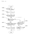
Embodiment 2, a pattern in which theoutdoor unit 3 is not of the type which allows reduction of the power consumption in the standby condition will be described. -
Fig. 7 is an electric component system block diagram of an air conditioner according toEmbodiment 2.
Subsequently, a configuration of theoutdoor unit 3 inEmbodiment 2 will be described with a particular emphasis on different points fromEmbodiment 1.
Theindoor unit 2 inEmbodiment 2 has the similar configuration asEmbodiment 1, and the same numbers reference the same parts. - As shown in
Fig. 7 , theoutdoor unit 3 inEmbodiment 2 does not include the inrushcurrent preventing relay 19, the inrush current preventingrelay coil 20, and the powersupply cutoff relay 21 which have been described in conjunction with Embodiment 1 (Fig. 1 ). Other parts of the configuration are the same as those in Embodiment1, and the same numbers reference the same parts. - The
outdoor unit 3 inEmbodiment 2 is not of the type which allows reduction of the power consumption in the standby condition. For example, it is theoutdoor unit 3 having an electric component system in the related art.
The configuration of theoutdoor unit 3 is not limited thereto, and may be varied as long as it is connected to theindoor unit 2 by the three core cable including thepower line 8, the power signalcommon line 9, and thesignal line 16. - The
outdoor relay 11 is connected at one end thereof to the terminal L on theoutdoor terminal base 31 and at the other end thereof to theoutdoor rectifier 12 in the same manner asEmbodiment 1.
The inrushcurrent preventing resistance 10 is provided in parallel with theoutdoor relay 11. The inrushcurrent preventing resistance 10 is connected at one end thereof to the terminal L on theoutdoor terminal base 31 and at the other end thereof to theoutdoor rectifier 12. - The power receiving
system data unit 26 inEmbodiment 2 stores information indicating that theoutdoor unit 3 connected to theindoor unit 2 is not of the type which allows reduction of the power consumption in the standby condition as standby condition power consumption reduction capability information. - In this configuration, the
utility power 7 supplied to the terminals L and N on theoutdoor terminal base 31 is supplied to theoutdoor rectifier 12 and the communication circuitpower supply unit 13 via the inrushcurrent preventing resistance 10 in the standby condition of theair conditioner 1. - The electric power from the
utility power 7 supplied to the terminals L and N of theoutdoor terminal base 31 is supplied from the terminals S1 and S2 of theoutdoor terminal base 31 to the terminals S1 and S2 of theindoor terminal base 30 of theindoor unit 2 via thepower line 8 and the power signalcommon line 9.
Then, to theindoor rectifier 4 the electric power of theutility power 7 supplied to the terminals S1 and S2 of theindoor terminal base 30 of theindoor unit 2 is input.
Theindoor rectifier 4 converts the input AC voltage to a given DC voltage. Theindoor rectifier 4 supplies the converted DC voltage to respective components of theindoor control unit 5 and theindoor unit 2. - The
indoor control unit 5 determines whether or not theoutdoor unit 3 connected to theindoor unit 2 is of the type which, allows reduction of the power consumption in the standby condition on the basis of the standby condition power consumption capability information stored in the power receivingsystem data unit 26.
InEmbodiment 2, since theoutdoor unit 3 is not of the type which allows reduction of the power consumption in the standby condition, theindoor control unit 5 does not effect the operation of theoutdoor activation relay 22. - Upon receipt of the operation start request or the operation standby signal from the
remote controller 17 via the receivingunit 18, theindoor control unit 5 effects the operation of the indoorcommunication circuit unit 6 to start communications with theoutdoor unit 3, and transmits the signal to theoutdoor unit 3. - Subsequently, an operation of the
outdoor unit 3 at the time of activation inEmbodiment 2 will be described. -
Fig. 8 is a flowchart showing an operation of the outdoor unit according toEmbodiment 2.
Subsequently, respective steps shown inFig. 8 will be described. - The
utility power 7 being supplied to the terminals L and N on theoutdoor terminal base 31 is supplied to theoutdoor rectifier 12 via the communication circuitpower supply unit 13 and the inrushcurrent preventing resistance 10.
Then, theoutdoor rectifier 12 converts an AC voltage supplied from theutility power 7 to a given DC voltage, and supplies the same to theoutdoor control unit 15, thecapacitor 25, and the inverter circuit, 23.
The communication circuitpower supply unit 13 converts an AC voltage supplied from theutility power 7 to a given DC voltage and supplies the same to the outdoorcommunication circuit unit 14. - The
outdoor control unit 15 effects the operation of the outdoorcommunication circuit unit 14 to start communications with theindoor unit 2.
The outdoorcommunication circuit unit 14 starts communications with the indoorcommunication circuit unit 6 via the power signalcommon line 9 and thesignal line 16. - The
outdoor control unit 15 determines whether or not communications between the outdoorcommunication circuit unit 14 and the indoorcommunication circuit unit 6 of theindoor unit 2 are established. - When the communications between the outdoor
communication circuit unit 14 and theindoor unit 2 are established, the communications with theindoor unit 2 are started.
Theoutdoor control unit 15 determines a request signal from theindoor unit 2. When the request signal from theindoor unit 2 is an operation standby signal, theoutdoor control unit 15 is brought into a state of waiting an operation start request signal. - When the request signal from the
indoor unit 2 is the operation standby signal, theoutdoor control unit 15 turns the outdoor relay ON (short circuit). - The
outdoor control unit 15 carries out communications with theindoor unit 2 via the outdoorcommunication circuit unit 14, and causes theair conditioner 1 to perform the cooling operation or the heating operation. - In contrast, if the communications between the outdoor
communication circuit unit 14 and theindoor unit 2 cannot be established inStep 25, theoutdoor control unit 15 effects the operation of the outdoorcommunication circuit unit 14 again to start communications with theindoor unit 2.
Then, theoutdoor control unit 15 determines whether or not the communications between the outdoorcommunication circuit unit 14 and theindoor unit 2 are established within the predetermined time (n seconds). - If the communications between the outdoor
communication circuit unit 14 and theindoor unit 2 are not established within n seconds inStep 31, theoutdoor control unit 15 determines that the communications are abnormal. - As described the above, in the present embodiment, even when the
outdoor unit 3 is not of the type which allows reduction of the power consumption in the standby condition, theindoor unit 2 and theoutdoor unit 3 are connected by the three core cable including thepower line 8, the power signalcommon line 9, and thesignal line 16. Therefore, the control is achieved without increasing the number of the connecting cable between theindoor unit 2 and theoutdoor unit 3 from three cores. - In addition, even when the
outdoor unit 3 always requires the supply of the electric power of theutility power 7, theindoor unit 2 which allows the reduction of the standby condition power consumption can be connected thereto. - Since the
indoor unit 2 and theoutdoor unit 3 are connected by the three core cable including thepower line 8, the power signalcommon line 9, and thesignal line 16, theoutdoor unit 3 of the model in the related art can be connected to theindoor unit 2 without developing the substrate and software. - The connection of the
indoor unit 2 and theoutdoor unit 3 is also possible even when the levels of development of the standby condition power consumption reduction capability thereof are different. - In
Embodiment 3, a pattern in which theutility power 7 is connected to theindoor unit 2 will be described. -
Fig. 9 is an electric component system block diagram of an air conditioner according toEmbodiment 3.
Subsequently, a configuration of theair conditioner 1 inEmbodiment 3 will be described with a particular emphasis on different points fromEmbodiments - As shown in
Fig. 9 , theindoor unit 2 according toEmbodiment 3 includes a52C relay 27 in addition to the configuration inEmbodiment 1. (Fig. 1 ) .
Theindoor terminal base 30 inEmbodiment 3 includes terminals N, L in addition to the configuration in Embodiment 1 (Fig. 1 ). - The
52C relay 27 is connected at one end thereof to the terminal S1 on theindoor terminal base 30 and at the other end to theindoor rectifier 4. The52C relay 27 opens a contact point in the stationary state (normally open), and closes the contact point when the operation is effected by theindoor control unit 5. - The
utility power 7 is connected to the terminals L and N on theindoor terminal base 30 of theindoor unit 2.
The terminal L on theindoor terminal base 30 is connected to a point between the52C relay 27 and theindoor rectifier 4.
The terminal N on theindoor terminal base 30 is connected to a point between the terminal S2 on theindoor terminal base 30 and theindoor rectifier 4.
Accordingly, theutility power 7 supplied to the terminals L and N on theindoor terminal base 30 is input to theindoor rectifier 4. Theindoor rectifier 4 converts the input AC voltage to a given DC voltage. Theindoor rectifier 4 supplies the converted DC voltage to respective components of theindoor control unit 5 and theindoor unit 2. - The power receiving
system data unit 26 inEmbodiment 3 stores information indicating that theoutdoor unit 3 connected to theindoor unit 2 is not of the type which allows reduction of the power consumption in the standby condition as the standby condition power consumption reduction capability information.
The power receivingsystem data unit 26 also stores information indicating that theindoor unit 2 employs the indoor power receiving system. - Other parts of the configuration of the
indoor unit 2 are the same as those inEmbodiment 1, and the same numbers reference the same parts.
The52C relay 27 corresponds to an "indoor power distribution relay" in the invention. - The
outdoor unit 3 inEmbodiment 3 has a configuration in which the terminals L and N on theoutdoor terminal base 31 are not provided and theutility power 7 is not connected thereto in contrast to the configuration of Embodiment 2 (Fig. 7 ).
As shown inFig. 9 , the terminal S1 on theoutdoor terminal base 31 and theoutdoor relay 11 are connected directly without the intermediary of the terminal L. The terminal S2 on theoutdoor terminal base 31 and theoutdoor rectifier 12 are connected directly without the intermediary of the terminal N. - Other parts of the configuration of the
indoor unit 3 are the same as those inEmbodiment 2, and the same numbers reference the same parts. - Although the configuration in which the terminals L and N are not provided on the
outdoor terminal base 31 is shown inFig. 9 , the invention is not limited thereto, and a configuration similar to theoutdoor unit 3 in Embodiment 2 (Fig. 7 ) in which theutility power 7 is not connected to theoutdoor unit 3 is also applicable. - The configuration of the
outdoor unit 3 is not limited thereto, and may be varied as long as it is connected to theindoor unit 2 by the three core cable including thepower line 8, the power signalcommon line 9, and thesignal line 16, and theutility power 7 is not connected thereto. - Subsequently, supply of power when the
air conditioner 1 is in the standby condition will be described. - As shown in
Fig. 9 , theutility power 7 is supplied to the terminals L and N on theindoor terminal base 30 of theindoor unit 2. Then, theutility power 7 is input to theindoor rectifier 4.
Theindoor rectifier 4 converts the input AC voltage to a given DC voltage. Theindoor rectifier 4 supplies the converted DC voltage to respective components of theindoor control unit 5 and theindoor unit 2. - The
indoor control unit 5 determines whether theair conditioner 1 employs the indoor power receiving system or the outdoor power receiving system on the basis of data stored in the power receivingsystem data unit 26 and, when it is determined to be the indoor power receiving system, enables the control of the52C relay 27. - The
indoor control unit 5 determines whether or not theoutdoor unit 3 connected to theindoor unit 2 is of the type which allows reduction of the power consumption in the standby condition on the basis of the standby condition power consumption reduction capability information stored in the power receivingsystem data unit 26.
InEmbodiment 3, since theoutdoor unit 3 is not of the type which allows reduction of the power consumption in the standby condition, theindoor control unit 5 does not operate theoutdoor activation relay 22. - The
outdoor activation relay 22 connects the terminal S3 on theindoor terminal base 30 and the indoorcommunication circuit unit 6 in the stationary state.
Accordingly, the indoorcommunication circuit unit 6 is connected to theoutdoor unit 3 via thesignal line 16, and is brought into a state of being capable of establishing communications with theoutdoor unit 3.
At the same time, theindoor control unit 5 is brought into a state of waiting for the reception of an operation start request signal transmitted from theremote controller 17 and received via the receivingunit 18. - In contrast, the
52C relay 27 opens the contact point in the stationary state.
Therefore, noutility power 7 is supplied between the terminals S1 and S2 on theindoor terminal base 30, so that theutility power 7 is not supplied to theoutdoor unit 3.
Therefore, in the standby condition, the power source supply to the respective components of theoutdoor unit 3 is cut off, so that reduction of the power consumption of theoutdoor unit 3 in the standby condition is achieved. - Subsequently, an operation of the
indoor unit 2 at the time of activation inEmbodiment 3 will be described. -
Fig. 10 is a flowchart showing an operation of the indoor unit according toEmbodiment 3.
Subsequently, respective steps shown inFig. 10 will be described. - The
indoor control unit 5 receives an operation start request from theremote controller 17 via the receivingunit 18. - The
indoor control unit 5 effects the operation (ON) of the52C relay 27, and connects the terminal L on theindoor terminal base 30 and the terminal S1 on theindoor terminal base 30.
Accordingly, theutility power 7 is supplied between thepower line 8 and the power signalcommon line 9. - The
indoor control unit 5 effects the operation of the indoorcommunication circuit unit 6 to start the communications with theoutdoor unit 3. - The
indoor control unit 5 determines whether or not the communication between the indoorcommunication circuit unit 6 and the outdoorcommunication circuit unit 14 of theoutdoor unit 3 is established. - When the communication between the indoor
communication circuit unit 6 and theoutdoor unit 3 is established, the indoorcommunication circuit unit 6 starts communications with the outdoorcommunication circuit unit 14 of theoutdoor unit 3. - The
indoor control unit 5 carries out communications with theoutdoor unit 3 via the indoorcommunication circuit unit 6, and causes theair conditioner 1 to perform the cooling operation or the heating operation. - In contrast, if the communications between the indoor
communication circuit unit 6 and theoutdoor unit 3 cannot be established in Step 36, theindoor control unit 5 effects the operation of the indoorcommunication circuit unit 6 again to start communications with theoutdoor unit 3.
Then, theindoor control unit 5 determines whether or not the communications between the indoorcommunication circuit unit 6 and theoutdoor unit 3 are established within the predetermined time (n seconds). - If the communications between the indoor
communication circuit unit 6 and theoutdoor unit 3 cannot be established within n seconds in Step 39, theindoor control unit 5 determines that the communication is abnormal. - Subsequently, an operation of the
outdoor unit 3 at the time of activation will be described. - When the electric power from the
utility power 7 is supplied between thepower line 8 and the power signalcommon line 9 in Step 34 described above, the electric power from theutility power 7 is supplied to the terminals S1 and S2 on theoutdoor terminal base 31 of theoutdoor unit 3.
When the electric power from theutility power 7 is supplied to the terminals S1 and S2 on theoutdoor terminal base 31, the power is supplied to theoutdoor rectifier 12 and the communication circuitpower supply unit 13 via the inrushcurrent preventing resistor 10.
Theoutdoor rectifier 12 converts an AC voltage supplied from theutility power 7 to a given DC voltage, and supplies the same to theoutdoor control unit 15, thecapacitor 25, and theinverter circuit 23.
The communication circuitpower supply unit 13 converts an AC voltage supplied from theutility power 7 to a given DC voltage and supplies the same to the outdoorcommunication circuit unit 14. - Operations from then onward are the same as those in
Step 24 to Step 32 inEmbodiment 2. - As described above, in
Embodiment 3, even when theoutdoor unit 3 is not of the type which allows reduction of the power consumption in the standby condition, the 52C relay is brought into an opened state to cut off the power supply from theutility power 7 to theoutdoor unit 3 in the standby condition. Therefore, the standby condition power consumption consumed by theoutdoor unit 3 in the standby condition is reduced.
Even in the indoor power receiving system in which theutility power 7 is connected to theindoor unit 2, theindoor unit 2 and theoutdoor unit 3 are connected by the three core cable including thepower line 8, the power signalcommon line 9, and thesignal line 16. Therefore, the control is achieved as-is without increasing the number of cores of the connecting cable between theindoor unit 2 and theoutdoor unit 3 from three.
For example, in theoutdoor unit 3 of a model in the related art, theoutdoor unit 3 of the model in the related art can be connected to theindoor unlit 2 without developing the substrate and the software.
The connection of theindoor unit 2 and theoutdoor unit 3 is also possible even when the levels of development of the standby condition power consumption reduction capability thereof are different.
The indoor control substrate and the control may be commonly used irrespective of the power receiving mode of theutility power 7 and the connection to the outdoor unit of the prior year model. - In
Embodiment 3, the case of theoutdoor unit 3 having no inrushcurrent preventing relay 19 provided therein and not allowing the reduction of the power consumption in the standby condition has been described. The invention is not limited thereto, and theoutdoor unit 3 which allows the reduction of the power consumption in the standby condition described inEmbodiment 1 may be connected as theoutdoor unit 3.
In this case, in addition to the operations described above, theindoor control unit 5 makes a reference to data in the power receivingsystem data unit 26, and effects the operation of theoutdoor activation relay 22 when theoutdoor unit 3 is of the type which allows the reduction of the power consumption in the standby condition and theutility power 7 is supplied to theindoor unit 2.
With such the configuration and the operation, the same advantages are achieved. - In
Embodiment 4, the mode of theair conditioner 1 in a multiple connection having a plurality of the indoor units will be described. -
Fig. 11 is an electric component system block diagram of an air conditioner in the standby condition according toEmbodiment 4.
As shown inFig. 11 , inEmbodiment 4, a plurality of the indoor units are provided.
InEmbodiment 4, a case where two indoor units, that is, anindoor unit A 28 and anindoor unit B 29 are provided will be described.
The configurations of theindoor unit A 28 and theindoor unit B 29 are the same as theindoor unit 2 in Embodiment 1 (Fig. 1 ), and the same numbers reference the same parts.
The number of the indoor units is not limited thereto, and three or more of those may be provided. - The
indoor unit A 28 and theindoor unit B 29 each are connected to theoutdoor unit 3 respectively by the three core cable including thepower line 8, the power signalcommon line 9, and thesignal line 16.
Theoutdoor terminal base 31 of theoutdoor unit 3 is provided with two sets of the terminals S1, S2 and S3 corresponding to theindoor unit A 28 and theindoor unit B 29.
The terminal S1 on theoutdoor terminal base 31 is connected to the respective terminals S1 on theoutdoor terminal base 31.
The terminal S2 on theoutdoor terminal base 31 is connected to the respective terminals S2 on theoutdoor terminal base 31.
The terminal S3 on theoutdoor terminal base 31 is connected to the respective terminals S3 on theoutdoor terminal base 31. - The
outdoor unit 3 inEmbodiment 4 includes the outdoorcommunication circuit units 14 according to the number of the indoor units to be connected in addition to the configuration in Embodiment 1 (Fig. 1 ).
The outdoorcommunication circuit units 14 each are connected at one end thereof to the communication circuitpower supply unit 13, and at the other end thereof to the terminal S3 to which thesignal line 16 of the indoor unit corresponding thereto is connected. - The
outdoor unit 3 is provided with the power supply cutoff relays 21 according to the number of the indoor units to be connected.
The power supply cutoff relays 21 each are connected at one end to the inrush current preventingrelay coil 20 and at the other end to the terminal S3 to which thesignal line 16 of the indoor unit corresponding to the outdoorcommunication circuit unit 14 is connected. - Other parts of the configuration of the
outdoor unit 3 are the same as those inEmbodiment 1, and the same number reference the same parts. - First of all, the supply of power in the
air conditioner 1 in the standby condition will be described. - The
utility power 7 supplied to the terminals L and N on theoutdoor terminal base 31 is supplied from the terminals S1 and S2 on theoutdoor terminal base 31 to the terminals S1 and S2 on theindoor terminal bases 30 of theindoor unit A 28 and theindoor unit B 29 via thepower line 8 and the power signalcommon line 9.
Then, theindoor rectifiers 4 each receive an input of the power of theutility power 7 supplied to the terminals S1 and S2 on the indoor terminal bases 30.
Theindoor rectifier 4 converts the input AC voltage to a given DC voltage. Theindoor rectifier 4 supplies the converted DC voltage to respective components of theindoor control unit 5 and theindoor unit 2. - The
indoor control unit 5 determines whether theair conditioner 1 employs the indoor power receiving system or the outdoor power receiving system on the basis of data stored in the power receivingsystem data unit 26 and, when it is determined to be the outdoor power receiving system, enables the control of theoutdoor activation relay 22.
Theindoor control unit 5 determines whether or not theoutdoor unit 3 connected to theindoor unit 2 is of the type which allows reduction of the power consumption in the standby condition on the basis of the standby condition power consumption reduction capability information stored in the power receivingsystem data unit 26. - The
outdoor activation relay 22 connects the terminal S3 on theindoor terminal base 30 and the indoorcommunication circuit unit 6 in the stationary state.
Accordingly, the each indoorcommunication circuit unit 6 is connected to theoutdoor unit 3 via thesignal line 16, and is brought into a state of being capable of establishing communications with theoutdoor unit 3.
At the same time, theindoor control unit 5 is brought into a state of waiting for the reception of an operation start request signal transmitted from theremote controller 17 and received via the receivingunit 18. - The contact points of the
outdoor relay 11 and the inrushcurrent preventing relay 19 of theoutdoor unit 3 are opened in the stationary state.
At the same time, each of the respective outdoor activation relays 22 of theindoor unit A 28 and theindoor unit B 29 opens the connection between the terminal S3 on theindoor terminal base 30 and the outdoorpower supply line 24.
Therefore, noutility power 7 is supplied between the terminals S2 and S3 on theoutdoor terminal base 31, so that the inrush current preventingrelay coil 20 is in the non-energized state.
Therefore, even when theutility power 7 is supplied to the terminals L and N on theoutdoor terminal base 31 of theoutdoor unit 3, the inrushcurrent preventing relay 19 and theoutdoor relay 11 are each brought into an opened state.
Therefore, in the standby condition, the power source supply to the respective components connected to downstream of the inrushcurrent preventing relay 19 and theoutdoor relay 11 is cut off, so that reduction of the standby condition power consumption of theoutdoor unit 3 in the standby condition is achieved. - Subsequently, the operation of the outdoor unit of the air conditioner at the time of activation and during operation will be described.
-
Fig. 12 is an electric component system block diagram of the air conditioner according toEmbodiment 4 in which one of the indoor units is activated.
Fig. 13 is an electric component system block diagram of the air conditioner according toEmbodiment 4 in which one of the indoor units is in operation.
The operation to activate theoutdoor unit 3 when an operation start request is transmitted from theremote controller 17 only to theindoor unit A 28 will be described. - When the operation start request is transmitted from the
remote controller 17 to theindoor unit A 28, theindoor control unit 5 of theindoor unit A 28 receives the operation start request via the receivingunit 18.
Operations from then onward of theindoor unit A 28 are the same as those inStep 1 to Step 11 inEmbodiment 1. - Subsequently, an operation of the
outdoor unit 3 will be described. -
Fig. 14 is a flowchart showing an operation of the outdoor unit according toEmbodiment 4.
Referring now toFig. 12 andFig. 13 , description will be given on the basis of respective steps inFig. 14 . - When the
outdoor activation relay 22 of theindoor unit A 28 is turned ON and theutility power 7 is supplied between thesignal line 16 and the power signalcommon line 9, theutility power 7 is supplied between the terminals S2 and S3 on theoutdoor terminal base 31 of theoutdoor unit 3. - When the
utility power 7 is supplied between the terminals S2 and S3 on theoutdoor terminal base 31, the inrush current preventingrelay coil 20 is energized via the power supply cutoff relays 21, and makes the inrush current preventingrelay 19 short-circuited (seeFig. 12 ).
When the inrushcurrent preventing relay 19 is made short-circuited, theutility power 7 supplied to the terminals L and N on theoutdoor terminal base 31 is supplied to theoutdoor rectifier 12 and the communication circuitpower supply unit 13 via the inrushcurrent preventing resistance 10.
Theoutdoor rectifier 12 converts an AC voltage supplied from theutility power 7 to a given DC voltage, and supplies the same to theoutdoor control unit 15, thecapacitor 25, and theinverter circuit 23.
The communication circuitpower supply unit 13 converts an AC voltage supplied from theutility power 7 to a given DC voltage and supplies the same to the outdoorcommunication circuit units 14. - When the DC power is supplied from the
outdoor rectifier 12, theoutdoor control unit 15 makes theoutdoor relay 11 short-circuited. - Subsequently, the
outdoor control unit 15 effects the operations of all the power supply cutoff relays 21 to open the contact points. - When the power supply cutoff relays 21 are opened, the inrush current preventing
relay coil 20 is brought into a non-energized state, and the inrushcurrent preventing relay 19 is opened (seeFig. 13 ).
Accordingly, the short circuit between the terminals S2 and S3 on theoutdoor terminal base 31 is prevented during operation of theoutdoor unit 3, so that communications between the indoorcommunication circuit unit 6 and the outdoorcommunication circuit unit 14 are enabled. - Subsequently, the
outdoor control unit 15 effects the operations of all the outdoorcommunication circuit units 14 to start communications with theindoor unit A 28 or theindoor unit B 29.
The outdoorcommunication circuit units 14 each start communications with the indoorcommunication circuit unit 6 of the corresponding indoor unit via the power signalcommon line 9 and thesignal line 16. - The
outdoor control unit 15 determines whether or not communications between the respective outdoorcommunication circuit units 14 and the indoorcommunication circuit unit 6 of the corresponding indoor unit are established. - The
outdoor control unit 15 repeats Step 47 until the communications with the indoorcommunication circuit unit 6 of either one of theindoor unit A 28 or theindoor unit B 29 are established. - Since the indoor
communication circuit unit 6 of theindoor unit A 28 is in operation here, it is determined that communications between the outdoorcommunication circuit unit 14 and the indoorcommunication circuit unit 6 of theindoor unit A 28 are established.
In this case, theoutdoor unit 3 starts communication with theindoor unit A 28. - The
outdoor control unit 15 carries out communications with theindoor unit A 28 via the outdoorcommunication circuit unit 14, and causes theair conditioner 1 to perform the cooling operation or the heating operation. - Subsequently, an operation in a case where the operation start request is transmitted from the
remote controller 17 to theindoor unit B 29 when theindoor unit A 28 and theoutdoor unit 3 are in operation will be described. - When the operation start request is transmitted from the
remote controller 17 to theindoor unit B 29, theindoor control unit 5 of theindoor unit B 29 receives the operation start request via the receivingunit 18.
From then onward, establishment of the communications between the indoorcommunication circuit unit 6 of theindoor unit B 29 and theoutdoor unit 3 with the same operations as inStep 1 toStep 3 inEmbodiment 1 is achieved. - Here the
outdoor unit 3 is already in operation by the operations described above, and the outdoorcommunication circuit unit 14 to be connected to theindoor unit B 29 is repeating the establishment of communications, so that the establishment of communications between theindoor unit B 29 and theoutdoor unit 3 is achieved.
Therefore, theoutdoor control unit 15 of theindoor unit B 29 carries out the communications with theoutdoor unit 3 via the indoorcommunication circuit unit 6 by the operations inStep 3 andStep 9 inEmbodiment 1, and causes theair conditioner 1 to perform the cooling operation or the heating operation. - Subsequently, an operation to bring the
air conditioner 1 to the standby condition will be described. - In the same manner as in
Embodiment 1, theindoor control units 5 each receive an operation standby signal from theremote controller 17 via the corresponding receivingunit 18.
Theoutdoor control unit 15 of theoutdoor unit 3 receives the operation standby signal via the respective outdoorcommunication circuit units 14.
Theoutdoor control unit 15 effects the operation of theoutdoor relay 11 to open the contact point upon receipt of the operation standby signal from all the indoor units. - Accordingly, the power supply from the
utility power 7 to theoutdoor rectifier 12 and the communication circuitpower supply unit 13 via the terminals L and N on theoutdoor terminal base 31 is stopped, and the supply of the DC power to the respective components of theoutdoor unit 3 is also stopped.
With the operation as described above, transition to the standby condition described above (Fig. 11 ) is achieved again. - As described thus far, in
Embodiment 4, even when there are a plurality of the indoor units, connection between the respective indoor units and theoutdoor unit 3 is achieved as-is without increasing the number of cores of the connecting cable between the respective indoor units and theoutdoor unit 3 from three, and the reduction of the standby made power consumption in the standby condition is achieved. - 1:air conditioner, 2:indoor unit, 3: outdoor unit, 4: indoor rectifier, 5: indoor control unit, 6: indoor communication circuit unit, 7: utility power, 8: power line, 9: power signal common line, 10: inrush current preventing resistance, 11: outdoor relay, 12: outdoor rectifier, 13: communication circuit power supply unit, 14: outdoor communication circuit unit, 15: outdoor control unit, 16: signal line, 17: remote controller, 18: receiving unit, 19: inrush current preventing relay, 20: inrush current preventing relay coil, 21: power supply cutoff relay, 22: outdoor activation relay, 23: inverter circuit, 24: outdoor power supply line, 25: capacitor, 26: power receiving system data unit, 27: 52C relay, 28: indoor unit A, 29: indoor unit B, 30: indoor terminal base, 31: outdoor terminal base
Claims (9)
- An air conditioner, in which an indoor unit (2) and an outdoor unit (3) are provided, the indoor unit (2) and the outdoor unit (3) being connected by a three-core cable of a power line (8), a common line (9), and a signal line (16), and utility power (7) supplied to either the outdoor unit (3) or the indoor unit (2) is distributed via the power line (8) and the common line (9), wherein
the indoor unit (2) includes:an outdoor activation relay (22) configured to open and close a connection between the power line (8) and the signal line (16); andan indoor control unit (5) configured to effect the operation of the outdoor activation relay (22) to supply the utility power (7) between the signal line (16) and the common line (9), andthe indoor control unit (5) opens the connection between the power line (8) and the signal line (16) in a standby condition. - The air conditioner of claim 1, wherein the outdoor unit (3) includes:a power supply relay configured to open and close a connection of the utility power (7) supplied to the outdoor unit (3) and the outdoor unit (3); anda power supply relay coil configured to close the power supply relay when the utility power (7) is supplied between the signal line (16) and the common line (9).
- The air conditioner of claim 2, wherein a plurality of the indoor units (28,29) are provided,
the outdoor unit (3) is connected to the plurality of indoor units (28,29) by three core cables each including the power line (8), the common line (9), and the signal line (16), and
the power supply relay coil closes the power supply relay when the utility power (7) is supplied between the signal line (16) and the common line (9) which are connected to any one of the plurality of indoor units (28,29). - The air conditioner of any one of claims 1 to 3, wherein the indoor unit (2,28,29) includes an indoor communication circuit unit (6) configured to carry out communications with the outdoor unit (2,28,29) via the signal line (16) and the common line (9), and
the indoor control unit (5) operates the outdoor activation relay (22) for a predetermined time when the communication between the indoor communication circuit unit (6) and the outdoor unit (3) is not established when starting operation. - The air conditioner of claim 4, wherein the outdoor unit (3) includes:an outdoor communication circuit unit (14) configured to carry out communications with the indoor unit (2,28,29) via the signal line (16) and the common line (9);a power supply cutoff relay (21) configured to cut off energization of the power supply relay coil; andan outdoor control unit (15) configured to operates the power supply cutoff relay (21),the power supply relay includes:an outdoor relay (11) operated by the outdoor control unit (15); andan inrush current preventing relay (19) connected in parallel with the outdoor relay (11) and configured to be operated by energization of the power supply relay coil, andthe outdoor control unit (15) operates the outdoor relay (11) after a contact point of the inrush current preventing relay (19) is closed by a supply of the utility power (7) between the signal line (16) and the common line (9), opens the contact point by operating the power supply cutoff relay (21) after having closed the contact point of the outdoor relay (11), and operates the outdoor communication circuit unit (14) to start communication with the indoor unit (2, 28, 29) .
- The air conditioner of claim 1, wherein
a power receiving system data part (26) is provided, in which information to identify whether or not the outdoor unit (3) includes a power supply relay is stored,
and the indoor control unit (5) does not operates the outdoor activation relay (22) when the outdoor unit (3) does not have the power supply relay. - The air conditioner of claim 1, wherein the indoor unit (2) includes:an indoor power distribution relay (27) configured to open and close a connection between the utility power (7) supplied to the indoor unit (2) and the power line (8); anda power receiving system data unit (26), in which information for discriminating to which the utility power (7) is supplied, the outdoor unit (3) or the indoor unit (2), is stored, andthe indoor control unit (5) is configured to operate the indoor power distribution relay (27) on the basis of the information stored at least in the power receiving system data unit (26), and to supply the utility power (7) from the indoor unit (2) to the outdoor unit (3) via the power line (8) and the common line (9).
- The air conditioner of claim 7, wherein the power receiving system data unit (26) stores information for discriminating whether or not the outdoor unit (3) includes a power supply relay, and
the indoor control unit (5) does not operate the outdoor activation relay (22) when the outdoor unit (3) does not have the power supply relay. - The air conditioner of claim 7, wherein the outdoor unit (3) includes:a power supply relay configured to open and close a connection between the power line (8) and the outdoor unit (3); anda power supply relay coil configured to close the power supply relay when the utility power (7) is supplied between the signal line (16) and the common line (9),the power receiving system data unit (26) stores information for discriminating whether or not the outdoor unit (3) includes the power supply relay, andthe indoor control unit (5) operates the outdoor activation relay (22) when the outdoor unit (3) includes the power supply relay and the utility power (7) is supplied to the indoor unit.
Applications Claiming Priority (1)
| Application Number | Priority Date | Filing Date | Title |
|---|---|---|---|
| JP2009091723A JP5241585B2 (en) | 2009-04-06 | 2009-04-06 | Air conditioner |
Publications (3)
| Publication Number | Publication Date |
|---|---|
| EP2241831A1 true EP2241831A1 (en) | 2010-10-20 |
| EP2241831A8 EP2241831A8 (en) | 2011-02-09 |
| EP2241831B1 EP2241831B1 (en) | 2018-04-25 |
Family
ID=42235845
Family Applications (1)
| Application Number | Title | Priority Date | Filing Date |
|---|---|---|---|
| EP10002461.1A Active EP2241831B1 (en) | 2009-04-06 | 2010-03-09 | Air conditioner with reduced standby power consuption of the outdoor unit on the basis of a three wire cable connection between indoor and outdoor unit |
Country Status (3)
| Country | Link |
|---|---|
| EP (1) | EP2241831B1 (en) |
| JP (1) | JP5241585B2 (en) |
| ES (1) | ES2670725T3 (en) |
Cited By (17)
| Publication number | Priority date | Publication date | Assignee | Title |
|---|---|---|---|---|
| CN101847314A (en) * | 2010-04-28 | 2010-09-29 | 辛明 | Signal transmission method and transmission device for solar water heater |
| US8987946B2 (en) | 2011-12-28 | 2015-03-24 | Daikin Industries, Ltd. | Air conditioner |
| CN104487776A (en) * | 2012-04-25 | 2015-04-01 | 松下设备空调研发马来西亚公司 | Air conditioner |
| CN105337598A (en) * | 2014-07-29 | 2016-02-17 | 青岛海尔空调器有限总公司 | Air conditioner, and circuit having low stand-by power consumption and control method thereof |
| EP3056830A1 (en) * | 2015-02-11 | 2016-08-17 | Panasonic Appliances Air-Conditioning R&D Malaysia Sdn. Bhd. | Reduced power consumption in air conditioners |
| CN104214901B (en) * | 2014-09-25 | 2017-01-11 | 中国扬子集团滁州扬子空调器有限公司 | Out-of-communication control method of indoor unit of inverter air conditioner |
| EP2455676A3 (en) * | 2010-11-18 | 2017-09-06 | Johnson Controls-Hitachi Air Conditioning Technology (Hong Kong) Limited | Air conditioning apparatus |
| EP3208551A4 (en) * | 2016-01-06 | 2017-09-13 | Mitsubishi Electric Corporation | Air conditioner |
| EP2746685A3 (en) * | 2012-12-20 | 2017-12-27 | Mitsubishi Electric Corporation | Air conditioner |
| US9951966B2 (en) | 2014-11-07 | 2018-04-24 | Mitsubishi Electric Corporation | Air conditioner |
| KR20180109433A (en) * | 2017-03-28 | 2018-10-08 | 엘지전자 주식회사 | Air conditioner having power saving function |
| EP3379162A3 (en) * | 2017-03-24 | 2018-11-21 | Mitsubishi Heavy Industries Thermal Systems, Ltd. | Air conditioning system and control method |
| CN109270862A (en) * | 2018-10-01 | 2019-01-25 | 珠海格力电器股份有限公司 | Apparatus control method, control device and the equipment using the control device |
| EP3660406A4 (en) * | 2017-07-26 | 2020-08-12 | Mitsubishi Electric Corporation | Air conditioner |
| US11162700B2 (en) * | 2017-11-16 | 2021-11-02 | Qingdao Haier Air Conditioner General Corp., Ltd. | Method and apparatus for identifying air-conditioning circuit, and air conditioner |
| US11486600B2 (en) | 2018-03-26 | 2022-11-01 | Mitsubishi Electric Corporation | Air conditioner |
| US11506412B2 (en) | 2018-01-11 | 2022-11-22 | Mitsubishi Electric Corporation | Air conditioner |
Families Citing this family (23)
| Publication number | Priority date | Publication date | Assignee | Title |
|---|---|---|---|---|
| JP5289384B2 (en) * | 2010-06-01 | 2013-09-11 | 三菱電機株式会社 | Air conditioner |
| JP2012117704A (en) * | 2010-11-29 | 2012-06-21 | Mitsubishi Electric Corp | Air conditioner |
| JP5830719B2 (en) * | 2011-05-16 | 2015-12-09 | パナソニックIpマネジメント株式会社 | Control device for multi-room air conditioner |
| JP5873966B2 (en) * | 2011-06-17 | 2016-03-01 | パナソニックIpマネジメント株式会社 | Air conditioner |
| JP2013133974A (en) * | 2011-12-26 | 2013-07-08 | Panasonic Corp | Multi-type air conditioner |
| JP5502062B2 (en) * | 2011-12-26 | 2014-05-28 | 三菱電機株式会社 | Air conditioner |
| JP5403144B2 (en) * | 2011-12-28 | 2014-01-29 | ダイキン工業株式会社 | Air conditioner |
| JP5655775B2 (en) * | 2011-12-28 | 2015-01-21 | ダイキン工業株式会社 | Air conditioner |
| JP5772588B2 (en) * | 2011-12-28 | 2015-09-02 | ダイキン工業株式会社 | Air conditioner |
| JP5772587B2 (en) * | 2011-12-28 | 2015-09-02 | ダイキン工業株式会社 | Air conditioner |
| JP5246324B2 (en) * | 2011-12-28 | 2013-07-24 | ダイキン工業株式会社 | Air conditioner |
| JP5472333B2 (en) * | 2012-01-26 | 2014-04-16 | ダイキン工業株式会社 | Air conditioner |
| JP5661090B2 (en) * | 2012-12-20 | 2015-01-28 | 三菱電機株式会社 | Air conditioner |
| JP6231749B2 (en) * | 2013-01-23 | 2017-11-15 | 三菱電機株式会社 | Air conditioner |
| JP2014152968A (en) * | 2013-02-06 | 2014-08-25 | Mitsubishi Electric Corp | Air conditioner |
| JP6037884B2 (en) * | 2013-02-15 | 2016-12-07 | 三菱電機株式会社 | Air conditioner |
| JP5984732B2 (en) * | 2013-04-09 | 2016-09-06 | 三菱電機株式会社 | Air conditioner |
| CN104167643A (en) * | 2014-08-04 | 2014-11-26 | 珠海格力电器股份有限公司 | Plug, air conditioner and plug control method |
| KR101737364B1 (en) | 2015-08-31 | 2017-05-18 | 엘지전자 주식회사 | Air conditioner including the same |
| CN106440220B (en) * | 2016-10-12 | 2019-07-02 | 青岛海尔空调器有限总公司 | Air-conditioner standby circuit and air conditioner |
| WO2019049330A1 (en) | 2017-09-08 | 2019-03-14 | 三菱電機株式会社 | Air conditioner |
| KR102053986B1 (en) * | 2018-02-09 | 2019-12-09 | 엘지전자 주식회사 | Standby power device |
| WO2019155620A1 (en) * | 2018-02-09 | 2019-08-15 | 三菱電機株式会社 | Air conditioner |
Citations (5)
| Publication number | Priority date | Publication date | Assignee | Title |
|---|---|---|---|---|
| JP2000111123A (en) * | 1998-10-05 | 2000-04-18 | Daikin Ind Ltd | Separate type air-conditioner |
| EP1795823A1 (en) * | 2004-09-14 | 2007-06-13 | Daikin Industries, Ltd. | Separate type air conditioner |
| EP1830138A1 (en) * | 2004-11-29 | 2007-09-05 | Daikin Industries, Ltd. | Air conditioner |
| JP2007225128A (en) | 2006-02-21 | 2007-09-06 | Fujitsu General Ltd | Air conditioner |
| JP2009041857A (en) * | 2007-08-09 | 2009-02-26 | Sharp Corp | Air conditioner |
Family Cites Families (1)
| Publication number | Priority date | Publication date | Assignee | Title |
|---|---|---|---|---|
| JP2010054065A (en) * | 2008-08-26 | 2010-03-11 | Fujitsu General Ltd | Air conditioner |
-
2009
- 2009-04-06 JP JP2009091723A patent/JP5241585B2/en active Active
-
2010
- 2010-03-09 EP EP10002461.1A patent/EP2241831B1/en active Active
- 2010-03-09 ES ES10002461.1T patent/ES2670725T3/en active Active
Patent Citations (5)
| Publication number | Priority date | Publication date | Assignee | Title |
|---|---|---|---|---|
| JP2000111123A (en) * | 1998-10-05 | 2000-04-18 | Daikin Ind Ltd | Separate type air-conditioner |
| EP1795823A1 (en) * | 2004-09-14 | 2007-06-13 | Daikin Industries, Ltd. | Separate type air conditioner |
| EP1830138A1 (en) * | 2004-11-29 | 2007-09-05 | Daikin Industries, Ltd. | Air conditioner |
| JP2007225128A (en) | 2006-02-21 | 2007-09-06 | Fujitsu General Ltd | Air conditioner |
| JP2009041857A (en) * | 2007-08-09 | 2009-02-26 | Sharp Corp | Air conditioner |
Cited By (22)
| Publication number | Priority date | Publication date | Assignee | Title |
|---|---|---|---|---|
| CN101847314A (en) * | 2010-04-28 | 2010-09-29 | 辛明 | Signal transmission method and transmission device for solar water heater |
| EP2455676A3 (en) * | 2010-11-18 | 2017-09-06 | Johnson Controls-Hitachi Air Conditioning Technology (Hong Kong) Limited | Air conditioning apparatus |
| US8987946B2 (en) | 2011-12-28 | 2015-03-24 | Daikin Industries, Ltd. | Air conditioner |
| CN104487776A (en) * | 2012-04-25 | 2015-04-01 | 松下设备空调研发马来西亚公司 | Air conditioner |
| EP2864713A4 (en) * | 2012-04-25 | 2016-06-15 | Panasonic Appliances Air Conditioning R&D Malaysia Sdn Bhd | Air conditioner |
| EP2746685A3 (en) * | 2012-12-20 | 2017-12-27 | Mitsubishi Electric Corporation | Air conditioner |
| CN105337598A (en) * | 2014-07-29 | 2016-02-17 | 青岛海尔空调器有限总公司 | Air conditioner, and circuit having low stand-by power consumption and control method thereof |
| CN104214901B (en) * | 2014-09-25 | 2017-01-11 | 中国扬子集团滁州扬子空调器有限公司 | Out-of-communication control method of indoor unit of inverter air conditioner |
| US9951966B2 (en) | 2014-11-07 | 2018-04-24 | Mitsubishi Electric Corporation | Air conditioner |
| EP3056830A1 (en) * | 2015-02-11 | 2016-08-17 | Panasonic Appliances Air-Conditioning R&D Malaysia Sdn. Bhd. | Reduced power consumption in air conditioners |
| EP3208551A4 (en) * | 2016-01-06 | 2017-09-13 | Mitsubishi Electric Corporation | Air conditioner |
| AU2016383826B2 (en) * | 2016-01-06 | 2019-08-01 | Mitsubishi Electric Corporation | Air conditioner |
| AU2016383826C1 (en) * | 2016-01-06 | 2019-12-12 | Mitsubishi Electric Corporation | Air conditioner |
| US10742023B2 (en) | 2016-01-06 | 2020-08-11 | Mitsubishi Electric Corporation | Air conditioner |
| EP3379162A3 (en) * | 2017-03-24 | 2018-11-21 | Mitsubishi Heavy Industries Thermal Systems, Ltd. | Air conditioning system and control method |
| KR20180109433A (en) * | 2017-03-28 | 2018-10-08 | 엘지전자 주식회사 | Air conditioner having power saving function |
| US10775063B2 (en) | 2017-03-28 | 2020-09-15 | Lg Electronics Inc. | Power supply apparatus having power saving function and air conditioner including the same |
| EP3660406A4 (en) * | 2017-07-26 | 2020-08-12 | Mitsubishi Electric Corporation | Air conditioner |
| US11162700B2 (en) * | 2017-11-16 | 2021-11-02 | Qingdao Haier Air Conditioner General Corp., Ltd. | Method and apparatus for identifying air-conditioning circuit, and air conditioner |
| US11506412B2 (en) | 2018-01-11 | 2022-11-22 | Mitsubishi Electric Corporation | Air conditioner |
| US11486600B2 (en) | 2018-03-26 | 2022-11-01 | Mitsubishi Electric Corporation | Air conditioner |
| CN109270862A (en) * | 2018-10-01 | 2019-01-25 | 珠海格力电器股份有限公司 | Apparatus control method, control device and the equipment using the control device |
Also Published As
| Publication number | Publication date |
|---|---|
| EP2241831A8 (en) | 2011-02-09 |
| ES2670725T3 (en) | 2018-05-31 |
| JP2010243051A (en) | 2010-10-28 |
| EP2241831B1 (en) | 2018-04-25 |
| JP5241585B2 (en) | 2013-07-17 |
Similar Documents
| Publication | Publication Date | Title |
|---|---|---|
| EP2241831A1 (en) | Air conditioner with reduced standby power consuption of the outdoor unit on the basis of a three wire cable connection between indoor and outdoor unit | |
| JP5984732B2 (en) | Air conditioner | |
| EP2993421B1 (en) | Low-power consumption standby circuit device, air conditioner and control method for air conditioner | |
| EP2618457B1 (en) | Intelligent power distribution system and method | |
| CN101826749B (en) | Electric power management system and method for operation thereof | |
| CN101478176B (en) | Backup electric power system | |
| US8987947B2 (en) | Air conditioner | |
| JP2012117704A (en) | Air conditioner | |
| CN101165421A (en) | Air conditioner and method of controlling the same | |
| US8248058B2 (en) | Signal testing apparatus for load control system | |
| WO2013099277A1 (en) | Air conditioning device | |
| JP6797311B2 (en) | Air conditioner | |
| JP2014142107A (en) | Air conditioner | |
| JP2014156963A (en) | Air conditioner | |
| CN106440220B (en) | Air-conditioner standby circuit and air conditioner | |
| CN110500696B (en) | Control circuit and air conditioner | |
| EP3367559B1 (en) | Air conditioner | |
| JP5502062B2 (en) | Air conditioner | |
| JP5246324B2 (en) | Air conditioner | |
| JP2013139891A (en) | Air conditioner | |
| CN108418183B (en) | Control method of motor unit, heat pump system and storage medium | |
| CN109888578A (en) | Multifunctional access line apparatus and control method | |
| CN113251578B (en) | Multifunctional test process line automatic switching method, electronic equipment and storage medium | |
| US20240102686A1 (en) | Air conditioner | |
| CN213273305U (en) | Control cabinet, control system and air cooling unit |
Legal Events
| Date | Code | Title | Description |
|---|---|---|---|
| PUAI | Public reference made under article 153(3) epc to a published international application that has entered the european phase |
Free format text: ORIGINAL CODE: 0009012 |
|
| AK | Designated contracting states |
Kind code of ref document: A1 Designated state(s): AT BE BG CH CY CZ DE DK EE ES FI FR GB GR HR HU IE IS IT LI LT LU LV MC MK MT NL NO PL PT RO SE SI SK SM TR |
|
| AX | Request for extension of the european patent |
Extension state: AL BA ME RS |
|
| RTI1 | Title (correction) |
Free format text: AIR CONDITIONER WITH REDUCED STANDBY POWER CONSUMPTION OF THE OUTDOOR UNIT ON THE BASIS OF A THREE WIRE CABLE CONNECTION BETWEEN INDOOR AND OUTDOOR UNIT |
|
| 17P | Request for examination filed |
Effective date: 20110420 |
|
| RBV | Designated contracting states (corrected) |
Designated state(s): DE ES FR IT |
|
| GRAP | Despatch of communication of intention to grant a patent |
Free format text: ORIGINAL CODE: EPIDOSNIGR1 |
|
| INTG | Intention to grant announced |
Effective date: 20171004 |
|
| GRAS | Grant fee paid |
Free format text: ORIGINAL CODE: EPIDOSNIGR3 |
|
| GRAA | (expected) grant |
Free format text: ORIGINAL CODE: 0009210 |
|
| AK | Designated contracting states |
Kind code of ref document: B1 Designated state(s): DE ES FR IT |
|
| REG | Reference to a national code |
Ref country code: DE Ref legal event code: R096 Ref document number: 602010050119 Country of ref document: DE |
|
| REG | Reference to a national code |
Ref country code: ES Ref legal event code: FG2A Ref document number: 2670725 Country of ref document: ES Kind code of ref document: T3 Effective date: 20180531 |
|
| REG | Reference to a national code |
Ref country code: DE Ref legal event code: R097 Ref document number: 602010050119 Country of ref document: DE |
|
| PLBE | No opposition filed within time limit |
Free format text: ORIGINAL CODE: 0009261 |
|
| STAA | Information on the status of an ep patent application or granted ep patent |
Free format text: STATUS: NO OPPOSITION FILED WITHIN TIME LIMIT |
|
| 26N | No opposition filed |
Effective date: 20190128 |
|
| REG | Reference to a national code |
Ref country code: DE Ref legal event code: R084 Ref document number: 602010050119 Country of ref document: DE |
|
| REG | Reference to a national code |
Ref country code: ES Ref legal event code: GC2A Effective date: 20210113 |
|
| PGFP | Annual fee paid to national office [announced via postgrant information from national office to epo] |
Ref country code: FR Payment date: 20230208 Year of fee payment: 14 |
|
| PGFP | Annual fee paid to national office [announced via postgrant information from national office to epo] |
Ref country code: IT Payment date: 20230213 Year of fee payment: 14 Ref country code: DE Payment date: 20230131 Year of fee payment: 14 |
|
| P01 | Opt-out of the competence of the unified patent court (upc) registered |
Effective date: 20230512 |
|
| PGFP | Annual fee paid to national office [announced via postgrant information from national office to epo] |
Ref country code: ES Payment date: 20230404 Year of fee payment: 14 |