EP2241808A1 - A gas turbine engine and method of operation - Google Patents
A gas turbine engine and method of operation Download PDFInfo
- Publication number
- EP2241808A1 EP2241808A1 EP10008127A EP10008127A EP2241808A1 EP 2241808 A1 EP2241808 A1 EP 2241808A1 EP 10008127 A EP10008127 A EP 10008127A EP 10008127 A EP10008127 A EP 10008127A EP 2241808 A1 EP2241808 A1 EP 2241808A1
- Authority
- EP
- European Patent Office
- Prior art keywords
- air
- combustion
- liner wall
- moisture
- adjacent
- Prior art date
- Legal status (The legal status is an assumption and is not a legal conclusion. Google has not performed a legal analysis and makes no representation as to the accuracy of the status listed.)
- Granted
Links
- 238000000034 method Methods 0.000 title claims abstract description 30
- 238000002485 combustion reaction Methods 0.000 claims abstract description 74
- 239000000446 fuel Substances 0.000 claims abstract description 24
- 238000001816 cooling Methods 0.000 claims abstract description 12
- 238000011144 upstream manufacturing Methods 0.000 claims description 7
- 239000003570 air Substances 0.000 description 34
- 239000007789 gas Substances 0.000 description 15
- UGFAIRIUMAVXCW-UHFFFAOYSA-N Carbon monoxide Chemical compound [O+]#[C-] UGFAIRIUMAVXCW-UHFFFAOYSA-N 0.000 description 12
- 229910002091 carbon monoxide Inorganic materials 0.000 description 12
- 238000007789 sealing Methods 0.000 description 8
- 239000000463 material Substances 0.000 description 6
- 238000003466 welding Methods 0.000 description 6
- 230000015572 biosynthetic process Effects 0.000 description 4
- 238000009792 diffusion process Methods 0.000 description 4
- VNWKTOKETHGBQD-UHFFFAOYSA-N methane Chemical compound C VNWKTOKETHGBQD-UHFFFAOYSA-N 0.000 description 4
- 239000000203 mixture Substances 0.000 description 4
- 230000008569 process Effects 0.000 description 4
- XLYOFNOQVPJJNP-UHFFFAOYSA-N water Substances O XLYOFNOQVPJJNP-UHFFFAOYSA-N 0.000 description 4
- 230000004927 fusion Effects 0.000 description 3
- 239000007788 liquid Substances 0.000 description 3
- IJGRMHOSHXDMSA-UHFFFAOYSA-N Atomic nitrogen Chemical compound N#N IJGRMHOSHXDMSA-UHFFFAOYSA-N 0.000 description 2
- 239000004215 Carbon black (E152) Substances 0.000 description 2
- 241000237503 Pectinidae Species 0.000 description 2
- 239000012080 ambient air Substances 0.000 description 2
- 238000005219 brazing Methods 0.000 description 2
- 229930195733 hydrocarbon Natural products 0.000 description 2
- 150000002430 hydrocarbons Chemical class 0.000 description 2
- 238000007689 inspection Methods 0.000 description 2
- 238000009434 installation Methods 0.000 description 2
- 238000005304 joining Methods 0.000 description 2
- 238000004519 manufacturing process Methods 0.000 description 2
- 238000003801 milling Methods 0.000 description 2
- 238000012986 modification Methods 0.000 description 2
- 230000004048 modification Effects 0.000 description 2
- 239000003345 natural gas Substances 0.000 description 2
- 239000007800 oxidant agent Substances 0.000 description 2
- 230000009467 reduction Effects 0.000 description 2
- 235000020637 scallop Nutrition 0.000 description 2
- 230000007704 transition Effects 0.000 description 2
- 230000004323 axial length Effects 0.000 description 1
- 239000002551 biofuel Substances 0.000 description 1
- 230000003197 catalytic effect Effects 0.000 description 1
- 238000006243 chemical reaction Methods 0.000 description 1
- 238000010276 construction Methods 0.000 description 1
- 238000004512 die casting Methods 0.000 description 1
- 238000006073 displacement reaction Methods 0.000 description 1
- 238000010438 heat treatment Methods 0.000 description 1
- 230000000977 initiatory effect Effects 0.000 description 1
- 238000002347 injection Methods 0.000 description 1
- 239000007924 injection Substances 0.000 description 1
- 238000005495 investment casting Methods 0.000 description 1
- 238000003754 machining Methods 0.000 description 1
- 229910052751 metal Inorganic materials 0.000 description 1
- 239000002184 metal Substances 0.000 description 1
- 229910052757 nitrogen Inorganic materials 0.000 description 1
- 230000003647 oxidation Effects 0.000 description 1
- 238000007254 oxidation reaction Methods 0.000 description 1
- 230000003954 pattern orientation Effects 0.000 description 1
- 230000000149 penetrating effect Effects 0.000 description 1
- 238000005086 pumping Methods 0.000 description 1
- 238000010791 quenching Methods 0.000 description 1
- 230000004044 response Effects 0.000 description 1
- 238000007528 sand casting Methods 0.000 description 1
- 239000000779 smoke Substances 0.000 description 1
- 238000004528 spin coating Methods 0.000 description 1
- 238000009987 spinning Methods 0.000 description 1
- 239000000126 substance Substances 0.000 description 1
Images


Classifications
-
- F—MECHANICAL ENGINEERING; LIGHTING; HEATING; WEAPONS; BLASTING
- F23—COMBUSTION APPARATUS; COMBUSTION PROCESSES
- F23R—GENERATING COMBUSTION PRODUCTS OF HIGH PRESSURE OR HIGH VELOCITY, e.g. GAS-TURBINE COMBUSTION CHAMBERS
- F23R3/00—Continuous combustion chambers using liquid or gaseous fuel
- F23R3/002—Wall structures
-
- F—MECHANICAL ENGINEERING; LIGHTING; HEATING; WEAPONS; BLASTING
- F23—COMBUSTION APPARATUS; COMBUSTION PROCESSES
- F23L—SUPPLYING AIR OR NON-COMBUSTIBLE LIQUIDS OR GASES TO COMBUSTION APPARATUS IN GENERAL ; VALVES OR DAMPERS SPECIALLY ADAPTED FOR CONTROLLING AIR SUPPLY OR DRAUGHT IN COMBUSTION APPARATUS; INDUCING DRAUGHT IN COMBUSTION APPARATUS; TOPS FOR CHIMNEYS OR VENTILATING SHAFTS; TERMINALS FOR FLUES
- F23L7/00—Supplying non-combustible liquids or gases, other than air, to the fire, e.g. oxygen, steam
- F23L7/002—Supplying water
- F23L7/005—Evaporated water; Steam
-
- F—MECHANICAL ENGINEERING; LIGHTING; HEATING; WEAPONS; BLASTING
- F23—COMBUSTION APPARATUS; COMBUSTION PROCESSES
- F23R—GENERATING COMBUSTION PRODUCTS OF HIGH PRESSURE OR HIGH VELOCITY, e.g. GAS-TURBINE COMBUSTION CHAMBERS
- F23R3/00—Continuous combustion chambers using liquid or gaseous fuel
- F23R3/28—Continuous combustion chambers using liquid or gaseous fuel characterised by the fuel supply
-
- F—MECHANICAL ENGINEERING; LIGHTING; HEATING; WEAPONS; BLASTING
- F23—COMBUSTION APPARATUS; COMBUSTION PROCESSES
- F23D—BURNERS
- F23D2214/00—Cooling
-
- F—MECHANICAL ENGINEERING; LIGHTING; HEATING; WEAPONS; BLASTING
- F23—COMBUSTION APPARATUS; COMBUSTION PROCESSES
- F23D—BURNERS
- F23D2900/00—Special features of, or arrangements for burners using fluid fuels or solid fuels suspended in a carrier gas
- F23D2900/14—Special features of gas burners
- F23D2900/14681—Adding steam or water vapor to primary or secondary combustion air
-
- F—MECHANICAL ENGINEERING; LIGHTING; HEATING; WEAPONS; BLASTING
- F23—COMBUSTION APPARATUS; COMBUSTION PROCESSES
- F23R—GENERATING COMBUSTION PRODUCTS OF HIGH PRESSURE OR HIGH VELOCITY, e.g. GAS-TURBINE COMBUSTION CHAMBERS
- F23R2900/00—Special features of, or arrangements for continuous combustion chambers; Combustion processes therefor
- F23R2900/03045—Convection cooled combustion chamber walls provided with turbolators or means for creating turbulences to increase cooling
-
- Y—GENERAL TAGGING OF NEW TECHNOLOGICAL DEVELOPMENTS; GENERAL TAGGING OF CROSS-SECTIONAL TECHNOLOGIES SPANNING OVER SEVERAL SECTIONS OF THE IPC; TECHNICAL SUBJECTS COVERED BY FORMER USPC CROSS-REFERENCE ART COLLECTIONS [XRACs] AND DIGESTS
- Y02—TECHNOLOGIES OR APPLICATIONS FOR MITIGATION OR ADAPTATION AGAINST CLIMATE CHANGE
- Y02E—REDUCTION OF GREENHOUSE GAS [GHG] EMISSIONS, RELATED TO ENERGY GENERATION, TRANSMISSION OR DISTRIBUTION
- Y02E20/00—Combustion technologies with mitigation potential
- Y02E20/30—Technologies for a more efficient combustion or heat usage
-
- Y—GENERAL TAGGING OF NEW TECHNOLOGICAL DEVELOPMENTS; GENERAL TAGGING OF CROSS-SECTIONAL TECHNOLOGIES SPANNING OVER SEVERAL SECTIONS OF THE IPC; TECHNICAL SUBJECTS COVERED BY FORMER USPC CROSS-REFERENCE ART COLLECTIONS [XRACs] AND DIGESTS
- Y02—TECHNOLOGIES OR APPLICATIONS FOR MITIGATION OR ADAPTATION AGAINST CLIMATE CHANGE
- Y02T—CLIMATE CHANGE MITIGATION TECHNOLOGIES RELATED TO TRANSPORTATION
- Y02T50/00—Aeronautics or air transport
- Y02T50/60—Efficient propulsion technologies, e.g. for aircraft
Definitions
- the present invention generally relates to a gas turbine engine and more specifically to a combustion chamber of the engine with reduced emissions.
- Gas turbine engines operate according to a continuous-flow, Brayton cycle.
- a compressor section pressurizes an ambient air stream, fuel is added and the mixture is burned in a central combustor section.
- the combustion products expand through a turbine section where bladed rotors convert heat energy from the combustion products into mechanical energy for rotating one or more centrally mounted shafts.
- the shafts drive the forward compressor section, thus continuing the cycle.
- Gas turbine engines are compact and powerful power plants, making them suitably for powering aircraft, heavy equipment, ships and electrical power generators. In power generating applications, the combustion products also drive a separate power turbine attached to an electrical generator.
- NOx typically forms at the forward region, in the hottest area of the combustor where the fuel and combustion air mixture ignites to form the combustion flame.
- the CO emissions form as the combustion reaction propagates axially rearward down the axial length of the combustion chamber. More complete combustion reduces the CO emissions produced as the CO is converted to CO 2 by hotter combustion and/or longer residence time.
- One method of NOx reduction involves the injection of moisture such as water (H 2 O) or steam into land-based turbines.
- the H 2 O or steam may be injected at locations from the engine inlet to the combustor.
- Typical combustor locations include the fuel nozzle or injector and various locations along the combustor wall.
- the moisture quenches the combustion flame temperature and significantly reduces the formation of NOx.
- DLN 'Dry Low NOx'
- DLE 'Dry Low Emissions'
- DLN/DLE combustion a lean combustion mixture produces a lower combustion flame temperature.
- Yet another method of reducing NOx formation in land-based or aero turbines is to inject additional compressor air transversely into the combustion flame to quench the combustion flame temperature, thus reducing the formation of NOx.
- the level of CO emissions may actually increase due to the lower flame temperatures.
- combustion chambers During engine operation, combustion chambers contain flame temperatures in excess of about 3000 degrees Fahrenheit (1649 degrees Celsius). In order to operate for the number of years necessary to be economically viable, metal combustion chamber wall temperatures must not exceed about 1700 degrees Fahrenheit (927 degrees Celsius). Routinely subjecting a combustion chamber to temperatures above about 1700 degrees Fahrenheit (927 degrees Celsius) will eventually weaken the material, leading to oxidation, loss of material and part replacement.
- An upstream compressor 18 provides pressurized air 32 to a combustion chamber having an inner liner 58 and an outer shroud 62 circumscribing a portion of the inner liner 58.
- the inner liner 58 having a wall 74 with an inwardly facing hot side 76 and an outwardly facing cold side 78.
- the shroud 62 is spaced from the inner liner 58, forming an annulus 100 for accepting a pressurized air stream 32B therein.
- Heat transfer features 82 disposed on the cold side 78, exchange heat from the liner wall 74 to the air stream 32B.
- Methods of operation include introducing fuel and air inside a liner wall 74 without premixing, and producing combustion products without introducing any additional pressurized air adjacent the hot side 76.
- An exemplary industrial gas turbine engine 10 is circumferentially disposed about a central, longitudinal axis or axial centerline 12 as illustrated in Figure 1 .
- the engine 10 includes in series order from front to rear, low and high pressure compressor sections 16 and 18, a central combustor section 20 and high and low pressure turbine sections 22 and 24.
- a free turbine section 26 is disposed aft of the low pressure turbine 24.
- This application also extends to aero engines with a fan or gear driven fan, and engines with more or fewer sections than illustrated.
- incoming ambient air 30 becomes pressurized air 32 in the compressors 16 and 1 ⁇ .
- Fuel mixes with the pressurized air 32 in the combustor section 20, where it is burned. Once burned, combustion products 34 expand through turbine sections 22, 24 and power turbine 26.
- Turbine sections 22 and 24 drive high and low rotor shafts 36 and 38 respectively, which rotate in response to the combustion products and thus the attached compressor sections 18, 16.
- Free turbine section 26 may, for example, drive an electrical generator, pump, or gearbox (not shown).
- Figure 1 provides a basic understanding and overview of the various sections and the basic operation of an industrial gas turbine engine. It will become apparent to those skilled in the art that the present application is applicable to all types of gas turbine engines, including those with aerospace applications.
- a combustor case 40 forms an annular pressurized air passage 42, which receives a portion of the pressurized air 32 via a diffuser 44.
- Distributed circumferentially about the centerline 12 is an array of approximately cylindrical combustion chambers 46, also known as combustor cans.
- a fuel nozzle 48 delivers natural gas, diese1, home heating oil, aviation fuel, bio fuels or other fuels to each chamber 46. Water or steam may also be introduced through the fuel nozzle 48, or other locations upstream of, or within the combustion chambers 46.
- the fuel burns within each chamber 46 in rich and lean combustion zones 50, 52.
- the combustion products 34 then exist the chamber 46 through a louvered transition duct 54 to the high pressure turbine module 22.
- Each combustion chamber 46 broadly comprises a forward scoop 56, an inner liner 58, an aft ring 60 and an outer shroud 62.
- a front attachment 64 is affixed to the scoop 56 and secures each combustion chamber 46 to a diffuser case 66.
- the aft ring 60 fits within the transition duct 54 and secures the combustion chamber 46 at the rear.
- At least one of the chambers 46 may include an igniter retaining provision 68, which retains an igniter 69 for initiating a flame during start up.
- Transfer tubes ( Figure 7 ) may join adjacent chambers 46, allowing the combustion flame to propagate between chambers.
- One or more stepped louvers 70 are arranged between the scoop 56 and the inner liner 58.
- the scoop 56 is formed of a high strength material.
- the rearmost louver 70 has a shape that closely resembles the inner liner 58 to which it is joined.
- the rear louver 70 is joined to the inner liner 58 at a butt-type, forward joint 72.
- the forward joint 72 is preferably created via a fusion welding process.
- the fusion welded joint 72 can be formed manually or robotically.
- nondestructive inspection techniques such as x-ray, fluorescent penetrant, ultrasonic or similar techniques are used to ensure joint 72 integrity.
- the rear louver 70 is integrally formed with the inner liner 58 and joined to an upstream louver 70 using a lap style joint (not illustrated).
- a lap style joint requires samples to be removed destructively and inspected microscopically to ensure joint integrity.
- the lap joint inspection process adds an additional overhead cost to each of the combustion chambers 46.
- the shape of the inner liner 58 is substantially cylindrical.
- An inner liner wall 74 has a radial thickness and is defined by an internal, hot side 76 (facing the rich and lean combustion zones 50, 52) and an oppositely faced, external, cold side 78.
- the surface of the hot side 76 is relatively featureless, and the surface of the external cold side78 has a scalloped flange 80, heat transfer features 82 and bosses 84.
- the scalloped flange 80 is located proximate the forward joint 72, and extends radially outwardly from the cold side 78.
- the flange 80 comprises a plurality of circumferentially spaced scallops around the outer radial edge for introducing air.
- a plurality of heat transfer features 82 create an interrupted topology on the surface of the cold side 78.
- the features 82 preferably extend radially outwardly from the cold side 78; however, other heat transfer features such as voids or dimples in the cold side 78 and axial fins are also contemplated.
- a plurality of pedestals and/or dimples of various shapes and sizes may be arranged about the cold side 78. While feature 82 shapes such as spherical, square or other shapes may be also used, only cylindrical shaped pedestals of varying spacing are shown for brevity.
- the features 82 are sized and arranged to tailor the transfer of heat from the liner wall 74 to the cooling air 32B in the annulus 100 between the liner hot side 76 and shroud 62.
- the features 82 may be oriented in patterns such as axial rows or circumferential rows or can be non-linear or the patterns may be completely variable. In one example, the pattern orientation varies in the axial direction.
- the rich combustion zone 50 typically operates at a higher temperature than the lean zone 52, so the heat transfer features 82 are sized and arranged to remove a greater amount of localized heat.
- the pattern is tailored to remove an appropriate amount of heat.
- the features 82 vary in size and spacing in order to tailor the heat transfer capability. By tailoring the size and pattern of the heat transfer features 82, a varying amount of heat is removed from the liner wall 74 depending upon axial and circumferential location. Localized hot spots may require more heat transfer features 82 than cooler areas.
- the result of a varying pattern of features 82 is a substantially constant temperature profile about the inner liner wall 74.
- bosses 84 are spaced about the inner liner 58 at various axial and circumferential locations.
- a boss 84 is cylindrical shaped and includes a boss wall 86, bounded by a boss outer surface 88 and a boss bore 90.
- Each boss 84 extends radially outwardly from the cold side 78 with the bore 90 penetrating through the boss 84 and the inner liner wall 74.
- the boss wall 86 contains a radially outer sealing surface 92 that may be flat or arcuate.
- the shape of the sealing surface 92 is defined by a radius extending from a longitudinal, combustion chamber axis 94 to match the shape of the outer shroud 62.
- the shape of the sealing surface 92 may or may not be constant in the axial direction. Further details of the sealing surfaces 92 and their function are discussed later.
- the inner liner 58 is preferably formed from a high strength, high temperature capability material using an investment casting process. For example, die casting, sand casting, spin casting, chemical milling, conventional milling or other methods can also be used to form the liner. Although the scalloped fl.ange 80, heat transfer features 82 and bosses 84 may be formed separately and affixed to the inner liner via brazing, welding or machining for example, they are preferably formed with the inner liner 74 during manufacture.
- An aft ring 60 can be affixed to the inner liner 58 at an aft joint 96.
- the aft joint 96 is preferably a butt type joint and is similar in construction to the forward joint 72 discussed earlier.
- the aft ring 60 is formed of a high strength sheet material by spinning, press forming, joining or other suitable methods.
- a plurality of spaced tabs 98 extend radially outwardly from the ring 60 proximate the aft joint 96.
- a first end of the tabs 98 is affixed to the aft ring 60 and a second end is affixed to the shroud 62 by resistance welding or similar joining methods.
- the tabs 98 effectively space the shroud 62 from the inner liner 58 and affix the shroud 62 to the aft ring 60 at the aft end of the combustion chamber 46.
- the shroud 62 is affixed to the inner liner 74 at a forward or central location.
- the shroud 62 is approximately cylindrical shaped and circumscribes a portion of the inner liner 58, defining an annulus 100 therebetween.
- the shroud 62 is formed of a high temperature capability material.
- a number of apertures 102 penetrate the shroud 62 and are spaced about the shroud 62 as illustrated in Figure 4 . Some apertures 102 align with and correspond to the boss bores 90 while others do not. The function of the apertures 102 is determined by location. Apertures 102 corresponding to the boss bores 90 and disposed near the forward end of the shroud 62 introduce a portion of compressor air 32A to the rich combustion zone 50.
- the shroud 62 Since the shroud 62 is affixed to the aft ring 60 via the plurality of tabs 98, it is constrained from rearward axial movement. There is slight relative axial growth between the shroud 62 and the inner liner 58 due to thermal expansion differences, so the shroud 62 is not constrained proximate the forward joint 72. As the shroud 62 expands axially forward, it slides along the scalloped flange 80 and the sealing surface 92 of corresponding bosses 84.
- shroud apertures 102 communicate with the boss bores 90 in the inner liner 58.
- the shroud apertures 102 that communicate with the boss bores 90 are slightly larger than the boss bores 90 while also being slightly smaller than the boss outer surfaces 88. This overlap allows the boss sealing surface 92 to seat against the shroud 62, forming a substantial seal between the inner liner 58 and the shroud 62.
- the ratio of shroud aperture 102 diameter to boss bore 90 diameter to increase the farther the boss 84 is away from the aft ring 60. This accommodates the greater axial displacement of the shroud 62 proximate the forward joint 72.
- the size and location of the shroud apertures 102 and boss bores 90 and boss outer walls 88 are defined such that during engine operation the edges of the shroud apertures 102 do not block the boss bores 90 and also do not allow a leakage path to form between the shroud aperture 102 edges and the boss outer walls 88.
- each boss 84 provides a minimal clearance between the sealing surface 92 and the outer shroud 62 for enabling cold assembly in an engine.
- the sealing surface 92 moves outward radially and seats against the outer shroud 62 to form a substantial seal.
- the radial growth is determined to provide a substantial seal at operating temperatures and relative axial movement between the inner liner 58 and the outer shroud 62 at lower temperatures.
- a diffusion combustor system is defined broadly as a system where gaseous or liquid fuel is introduced into the combustion chamber without premixing in the pressurized air (also known as oxidizer air stream) prior to combustion. No additional pressurized air enters the chamber to film cool the hot side 76 of the inner liner wall 74. Moisture in the form of water or steam may also be introduced upstream of the combustor 20, through the fuel nozzle 48, or along the liner wall 74.
- a fuel nozzle 48 injects fuel, in the form of a liquid or a gas and in some examples fuel and moisture, into the combustion chamber 46.
- An igniter 69 initially lights the mixture in rich combustion zone 50 and, once lit, the flame propagates between adjacent combustion chambers 46 via cross over tubes (not shown).
- the low emissions combustor 20 uses the pressurized compressor air 32 exiting the diffuser 44 for various purposes.
- a combustion portion of the air 32A enters the rich combustion zone 50 axially through the fuel nozzle 48, scoop 56, and transversely through a forward array of boss bores 90 radially spanning the annulus 100 between the wall 74 and outer shroud 62.
- a cooling portion of the air 32B enters the annulus 100 through the scallops in flange 80 ( Figure 8 ) and through apertures 102. The cooling portion of the air 32B forms a blanket about the inner liner wall 74, eventually exiting the annulus 100 between the aft tabs 98 ( Figure 8 ).
- cooling portion of the air 32B remains in the annulus 100 and does not enter the rich or lean combustion zones 50, 52.
- a diffusion portion of the air 32C enters the lean combustion zone 52 transversely though an aft array of boss bores 90.
- the diffusion portion 32C conditions the radial profile and circumferential pattern of the combustion products for entry into the turbine 22.
- a film portion of the air 32D enters upstream of the inner liner 74 and shields the forward louvers 70 from the extreme temperatures proximate the fuel nozzle 48 exit.
- the cooling portion of air 32B interacts with the heat transfer features 82 to absorb heat from the liner wall 74.
- the apertures 102 directing the cooling portion of air 32B into the annulus 100 do not communicate with bosses 84, ensuring the cooling air portion 32B remains external of the rich and lean combustion zones 50, 52.
- the cooling air 32B forms a blanket about the liner 58, interacting with the heat transfer features 82.
- the size, shape and pattern of the heat transfer features 82 are tailored to maintain a substantially uniform liner wall 74 temperature.
Landscapes
- Engineering & Computer Science (AREA)
- Chemical & Material Sciences (AREA)
- Combustion & Propulsion (AREA)
- Mechanical Engineering (AREA)
- General Engineering & Computer Science (AREA)
- Turbine Rotor Nozzle Sealing (AREA)
Abstract
Description
- The present invention generally relates to a gas turbine engine and more specifically to a combustion chamber of the engine with reduced emissions.
- Gas turbine engines operate according to a continuous-flow, Brayton cycle. A compressor section pressurizes an ambient air stream, fuel is added and the mixture is burned in a central combustor section. The combustion products expand through a turbine section where bladed rotors convert heat energy from the combustion products into mechanical energy for rotating one or more centrally mounted shafts. The shafts, in turn, drive the forward compressor section, thus continuing the cycle. Gas turbine engines are compact and powerful power plants, making them suitably for powering aircraft, heavy equipment, ships and electrical power generators. In power generating applications, the combustion products also drive a separate power turbine attached to an electrical generator.
- Most power turbine applications provide base load power and peak power during high demand periods only. Other applications include a more continuous mode of operation such as a means to power natural gas pipeline pumping and powering military and commercial ships. Because most power turbine applications are land-based installations, the exhaust emissions typically require treatment to meet government, state and local clean air standards for unburned hydrocarbon (HC), oxides of nitrogen (NOx), carbon monoxide (CO) and smoke or airborn particulate. Most permanent installations include large stacks to redirect the exhaust stream upward while simultaneously providing treatment to lower emissions. Today, exhaust gases are treated with selective catalytic converters and other methods of exhaust clean up down stream of the engine. As the worldwide demand for electrical power continues to rise, air emissions standards are becoming ever more paramount and stringent.
- During the combustion process, different types of emissions are created at various times and areas in the combustor. NOx typically forms at the forward region, in the hottest area of the combustor where the fuel and combustion air mixture ignites to form the combustion flame. The CO emissions form as the combustion reaction propagates axially rearward down the axial length of the combustion chamber. More complete combustion reduces the CO emissions produced as the CO is converted to CO2 by hotter combustion and/or longer residence time.
- One method of NOx reduction involves the injection of moisture such as water (H2O) or steam into land-based turbines. The H2O or steam may be injected at locations from the engine inlet to the combustor. Typical combustor locations include the fuel nozzle or injector and various locations along the combustor wall. The moisture quenches the combustion flame temperature and significantly reduces the formation of NOx.
- Another method of reducing NOx formation in land-based or aero turbines is known as 'Dry Low NOx' (DLN) or 'Dry Low Emissions' (DLE) combustion. With DLN/DLE combustion, a lean combustion mixture produces a lower combustion flame temperature. Yet another method of reducing NOx formation in land-based or aero turbines is to inject additional compressor air transversely into the combustion flame to quench the combustion flame temperature, thus reducing the formation of NOx. However, by reducing the combustion flame temperature using any of these methods, the level of CO emissions may actually increase due to the lower flame temperatures.
- During engine operation, combustion chambers contain flame temperatures in excess of about 3000 degrees Fahrenheit (1649 degrees Celsius). In order to operate for the number of years necessary to be economically viable, metal combustion chamber wall temperatures must not exceed about 1700 degrees Fahrenheit (927 degrees Celsius). Routinely subjecting a combustion chamber to temperatures above about 1700 degrees Fahrenheit (927 degrees Celsius) will eventually weaken the material, leading to oxidation, loss of material and part replacement.
- What is presently needed is a combustion chamber for reducing both NOx and CO emissions, without negatively affecting component durability or the operational efficiencies of the other gas turbine engine sections.
- Provided are
gas turbine engines 10,combustion chambers 46 and methods of operation for reducing NOx and CO emissions in aerospace and industrial applications. Anupstream compressor 18 providespressurized air 32 to a combustion chamber having aninner liner 58 and anouter shroud 62 circumscribing a portion of theinner liner 58. Theinner liner 58 having awall 74 with an inwardly facinghot side 76 and an outwardly facingcold side 78. Theshroud 62 is spaced from theinner liner 58, forming anannulus 100 for accepting apressurized air stream 32B therein.Heat transfer features 82, disposed on thecold side 78, exchange heat from theliner wall 74 to theair stream 32B. - Methods of operation include introducing fuel and air inside a
liner wall 74 without premixing, and producing combustion products without introducing any additional pressurized air adjacent thehot side 76. - These and other objects, features and advantages of the present invention will become apparent in view of the following detailed description and accompanying figures illustrating various embodiments, where corresponding identifiers represent like features between the various figures.
-
-
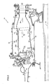
Figure 1 is a segmented cross section of a land-based gas turbine engine; -
Figure 2 is a cross section of a combustor of the gas turbine engine ofFigure 1 according to an embodiment of the present invention, with the lower half details removed for clarity; -
Figure 3 is a perspective view of a combustion chamber of the combustor ofFigure 2 ; -
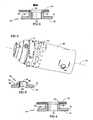
Figure 4 is a cross section of an aft liner to shroud seal of the combustion chamber ofFigure 3 taken along line 4-4; -
Figure 5 is a cross section of the a forward liner to shroud seal of the combustion chamber ofFigure 3 taken along line 5-5; -
Figure 6 is a cross section of a liner boss of the combustion chamber ofFigure 3 taken along line 6-6; -
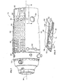
Figure 7 is a perspective view of the combustion chamber ofFigure 3 with the outer shroud partially removed to illustrate internal features; -
Figure 8 is a perspective cross section of a tab of the combustion chamber ofFigure 7 taken along line 8-8; and -
Figure 9 is a chart comparing the CO and NOx characteristics of a conventional, baseline combustion chamber with those of the present, low emissions combustion chamber. - An exemplary industrial
gas turbine engine 10 is circumferentially disposed about a central, longitudinal axis oraxial centerline 12 as illustrated inFigure 1 . Theengine 10 includes in series order from front to rear, low and highpressure compressor sections central combustor section 20 and high and lowpressure turbine sections free turbine section 26 is disposed aft of thelow pressure turbine 24. This application also extends to aero engines with a fan or gear driven fan, and engines with more or fewer sections than illustrated. - As is well known in the art of gas turbines, incoming
ambient air 30 becomespressurized air 32 in thecompressors 16 and 1ε. Fuel mixes with the pressurizedair 32 in thecombustor section 20, where it is burned. Once burned,combustion products 34 expand throughturbine sections power turbine 26.Turbine sections low rotor shafts compressor sections Free turbine section 26 may, for example, drive an electrical generator, pump, or gearbox (not shown). - It is understood that
Figure 1 provides a basic understanding and overview of the various sections and the basic operation of an industrial gas turbine engine. It will become apparent to those skilled in the art that the present application is applicable to all types of gas turbine engines, including those with aerospace applications. - Referring now to the
combustor module 20 ofFigure 2 , acombustor case 40 forms an annular pressurizedair passage 42, which receives a portion of the pressurizedair 32 via adiffuser 44. Distributed circumferentially about thecenterline 12 is an array of approximatelycylindrical combustion chambers 46, also known as combustor cans. Afuel nozzle 48 delivers natural gas, diese1, home heating oil, aviation fuel, bio fuels or other fuels to eachchamber 46. Water or steam may also be introduced through thefuel nozzle 48, or other locations upstream of, or within thecombustion chambers 46. The fuel burns within eachchamber 46 in rich andlean combustion zones combustion products 34 then exist thechamber 46 through alouvered transition duct 54 to the highpressure turbine module 22. - Each
combustion chamber 46 broadly comprises aforward scoop 56, aninner liner 58, anaft ring 60 and anouter shroud 62. In one example, afront attachment 64 is affixed to thescoop 56 and secures eachcombustion chamber 46 to adiffuser case 66. Theaft ring 60 fits within thetransition duct 54 and secures thecombustion chamber 46 at the rear. At least one of thechambers 46 may include anigniter retaining provision 68, which retains anigniter 69 for initiating a flame during start up. Transfer tubes (Figure 7 ) may joinadjacent chambers 46, allowing the combustion flame to propagate between chambers. - One or more stepped
louvers 70 are arranged between thescoop 56 and theinner liner 58. Thescoop 56 is formed of a high strength material. Preferably, therearmost louver 70 has a shape that closely resembles theinner liner 58 to which it is joined. - The
rear louver 70 is joined to theinner liner 58 at a butt-type, forward joint 72. Although resistance welding, flash butt welding, laser welding, brazing or other methods may be used, the forward joint 72 is preferably created via a fusion welding process. The fusion welded joint 72 can be formed manually or robotically. By using a fusion weld process to form the joint 72, nondestructive inspection techniques such as x-ray, fluorescent penetrant, ultrasonic or similar techniques are used to ensure joint 72 integrity. In other examples, therear louver 70 is integrally formed with theinner liner 58 and joined to anupstream louver 70 using a lap style joint (not illustrated). A lap style joint requires samples to be removed destructively and inspected microscopically to ensure joint integrity. The lap joint inspection process adds an additional overhead cost to each of thecombustion chambers 46. - Referring now to
Figures 3-7 , the shape of theinner liner 58 is substantially cylindrical. Aninner liner wall 74 has a radial thickness and is defined by an internal, hot side 76 (facing the rich andlean combustion zones 50, 52) and an oppositely faced, external,cold side 78. The surface of thehot side 76 is relatively featureless, and the surface of the external cold side78 has a scalloped flange 80, heat transfer features 82 andbosses 84. The scalloped flange 80 is located proximate the forward joint 72, and extends radially outwardly from thecold side 78. The flange 80 comprises a plurality of circumferentially spaced scallops around the outer radial edge for introducing air. - A plurality of heat transfer features 82 create an interrupted topology on the surface of the
cold side 78. Thefeatures 82 preferably extend radially outwardly from thecold side 78; however, other heat transfer features such as voids or dimples in thecold side 78 and axial fins are also contemplated. For example, a plurality of pedestals and/or dimples of various shapes and sizes may be arranged about thecold side 78. Whilefeature 82 shapes such as spherical, square or other shapes may be also used, only cylindrical shaped pedestals of varying spacing are shown for brevity. Thefeatures 82 are sized and arranged to tailor the transfer of heat from theliner wall 74 to the coolingair 32B in theannulus 100 between the linerhot side 76 andshroud 62. Thefeatures 82 may be oriented in patterns such as axial rows or circumferential rows or can be non-linear or the patterns may be completely variable. In one example, the pattern orientation varies in the axial direction. - The
rich combustion zone 50 typically operates at a higher temperature than thelean zone 52, so the heat transfer features 82 are sized and arranged to remove a greater amount of localized heat. In the rich andlean zones features 82 vary in size and spacing in order to tailor the heat transfer capability. By tailoring the size and pattern of the heat transfer features 82, a varying amount of heat is removed from theliner wall 74 depending upon axial and circumferential location. Localized hot spots may require more heat transfer features 82 than cooler areas. The result of a varying pattern offeatures 82 is a substantially constant temperature profile about theinner liner wall 74. - As best illustrated in
Figures 4-6 ,bosses 84 are spaced about theinner liner 58 at various axial and circumferential locations. In one example, aboss 84 is cylindrical shaped and includes aboss wall 86, bounded by a bossouter surface 88 and a boss bore 90. Eachboss 84 extends radially outwardly from thecold side 78 with thebore 90 penetrating through theboss 84 and theinner liner wall 74. Theboss wall 86 contains a radially outer sealingsurface 92 that may be flat or arcuate. Preferably, the shape of the sealingsurface 92 is defined by a radius extending from a longitudinal,combustion chamber axis 94 to match the shape of theouter shroud 62. The shape of the sealingsurface 92 may or may not be constant in the axial direction. Further details of the sealing surfaces 92 and their function are discussed later. - The
inner liner 58 is preferably formed from a high strength, high temperature capability material using an investment casting process. For example, die casting, sand casting, spin casting, chemical milling, conventional milling or other methods can also be used to form the liner. Although the scalloped fl.ange 80, heat transfer features 82 andbosses 84 may be formed separately and affixed to the inner liner via brazing, welding or machining for example, they are preferably formed with theinner liner 74 during manufacture. - An
aft ring 60 can be affixed to theinner liner 58 at an aft joint 96. The aft joint 96 is preferably a butt type joint and is similar in construction to the forward joint 72 discussed earlier. Theaft ring 60 is formed of a high strength sheet material by spinning, press forming, joining or other suitable methods. - Referring to the embodiment of
Figure 8 , a plurality of spacedtabs 98 extend radially outwardly from thering 60 proximate the aft joint 96. A first end of thetabs 98 is affixed to theaft ring 60 and a second end is affixed to theshroud 62 by resistance welding or similar joining methods. Thetabs 98 effectively space theshroud 62 from theinner liner 58 and affix theshroud 62 to theaft ring 60 at the aft end of thecombustion chamber 46. In other embodiments, theshroud 62 is affixed to theinner liner 74 at a forward or central location. - The
shroud 62 is approximately cylindrical shaped and circumscribes a portion of theinner liner 58, defining anannulus 100 therebetween. Theshroud 62 is formed of a high temperature capability material. A number ofapertures 102 penetrate theshroud 62 and are spaced about theshroud 62 as illustrated inFigure 4 . Someapertures 102 align with and correspond to the boss bores 90 while others do not. The function of theapertures 102 is determined by location.Apertures 102 corresponding to the boss bores 90 and disposed near the forward end of theshroud 62 introduce a portion ofcompressor air 32A to therich combustion zone 50.Apertures 102 corresponding to the boss bores 90 and disposed near the aft end of theshroud 62 introducecompressor air 32C into thelean combustion zone 52.Apertures 102 that do not align with or correspond to the boss bores 90 introducecompressor air 32B into theannulus 100. - Since the
shroud 62 is affixed to theaft ring 60 via the plurality oftabs 98, it is constrained from rearward axial movement. There is slight relative axial growth between theshroud 62 and theinner liner 58 due to thermal expansion differences, so theshroud 62 is not constrained proximate the forward joint 72. As theshroud 62 expands axially forward, it slides along the scalloped flange 80 and the sealingsurface 92 of correspondingbosses 84. - As described earlier, a number of the
shroud apertures 102 communicate with the boss bores 90 in theinner liner 58. Theshroud apertures 102 that communicate with the boss bores 90 are slightly larger than the boss bores 90 while also being slightly smaller than the boss outer surfaces 88. This overlap allows theboss sealing surface 92 to seat against theshroud 62, forming a substantial seal between theinner liner 58 and theshroud 62. Note that it is preferable for the ratio ofshroud aperture 102 diameter to boss bore 90 diameter to increase the farther theboss 84 is away from theaft ring 60. This accommodates the greater axial displacement of theshroud 62 proximate the forward joint 72. The size and location of theshroud apertures 102 and boss bores 90 and bossouter walls 88 are defined such that during engine operation the edges of theshroud apertures 102 do not block the boss bores 90 and also do not allow a leakage path to form between theshroud aperture 102 edges and the bossouter walls 88. - The radial height of each
boss 84 provides a minimal clearance between the sealingsurface 92 and theouter shroud 62 for enabling cold assembly in an engine. At operating temperatures, the sealingsurface 92 moves outward radially and seats against theouter shroud 62 to form a substantial seal. The radial growth is determined to provide a substantial seal at operating temperatures and relative axial movement between theinner liner 58 and theouter shroud 62 at lower temperatures. - A diffusion combustor system is defined broadly as a system where gaseous or liquid fuel is introduced into the combustion chamber without premixing in the pressurized air (also known as oxidizer air stream) prior to combustion. No additional pressurized air enters the chamber to film cool the
hot side 76 of theinner liner wall 74. Moisture in the form of water or steam may also be introduced upstream of thecombustor 20, through thefuel nozzle 48, or along theliner wall 74. - Referring back to
Figure 2 , a method of operation of the gas turbine engine andlow emissions combustor 20 is described in greater detail. Afuel nozzle 48 injects fuel, in the form of a liquid or a gas and in some examples fuel and moisture, into thecombustion chamber 46. Anigniter 69 initially lights the mixture inrich combustion zone 50 and, once lit, the flame propagates betweenadjacent combustion chambers 46 via cross over tubes (not shown). - The
low emissions combustor 20 uses thepressurized compressor air 32 exiting thediffuser 44 for various purposes. A combustion portion of theair 32A enters therich combustion zone 50 axially through thefuel nozzle 48,scoop 56, and transversely through a forward array of boss bores 90 radially spanning theannulus 100 between thewall 74 andouter shroud 62. A cooling portion of theair 32B enters theannulus 100 through the scallops in flange 80 (Figure 8 ) and throughapertures 102. The cooling portion of theair 32B forms a blanket about theinner liner wall 74, eventually exiting theannulus 100 between the aft tabs 98 (Figure 8 ). Again, note that the cooling portion of theair 32B remains in theannulus 100 and does not enter the rich orlean combustion zones air 32C enters thelean combustion zone 52 transversely though an aft array of boss bores 90. Thediffusion portion 32C conditions the radial profile and circumferential pattern of the combustion products for entry into theturbine 22. A film portion of theair 32D enters upstream of theinner liner 74 and shields theforward louvers 70 from the extreme temperatures proximate thefuel nozzle 48 exit. - The cooling portion of
air 32B interacts with the heat transfer features 82 to absorb heat from theliner wall 74. Note that theapertures 102 directing the cooling portion ofair 32B into theannulus 100 do not communicate withbosses 84, ensuring the coolingair portion 32B remains external of the rich andlean combustion zones annulus 100, the coolingair 32B forms a blanket about theliner 58, interacting with the heat transfer features 82. As was noted earlier, the size, shape and pattern of the heat transfer features 82 are tailored to maintain a substantiallyuniform liner wall 74 temperature. - In conventional, film-cooled combustors, the cooling film adjacent to the
hot side 76 of theinner liner wall 74 produces significant amounts of CO. With thecombustion chamber 46 of the present invention, more complete combustion results from the absence of a cooling film along thehot side 76. More complete combustion enhances the conversion of CO to CO2 without any increase in NOx emissions.Figure 9 illustrates the dramatic reduction in CO production at any given NOx level of a low emissions combustion chamber when compared to a traditional, film-cooled chamber. - Other alternatives, modifications and variations will become apparent to those skilled in the art having read the foregoing description. The methods are applicable to all diffusion combustor systems, which combust liquid or gaseous fuels that are not premixed with oxidizer air prior to combustion, and inject water or steam without introducing additional air to film cool the combustor. The terms front, forward, fore, rear, rearward and aft relate to standard gas turbine engine nomenclature with the compressor sections being in the front. Accordingly, the invention embraces those alternatives, modifications and variations as fall within the broad scope of the appended claims.
Claims (8)
- A method of combusting fuel with reduced emissions comprising the steps of:a. introducing a fuel inside of a liner wall without premixing in a pressurized air stream prior to ignition;b. producing a flowing stream of combustion products by igniting the fuel and air; andc. introducing no additional pressurized air inside and adjacent said liner wall for film cooling said liner wall, for reducing CO.
- The method set forth in claim 1 further comprising the step of:d. introducing moisture into the combustion products reducing NOx.
- The method set forth in claim 2 wherein the moisture is introduced upstream of said liner wall.
- The method set forth in claim 2 wherein the moisture is introduced along said liner wall.
- The method of claim 1 applied to a turbine engine having a combustion chamber defined by said liner wall, said liner wall having an inwardly facing hot side and an outwardly facing cold side, wherein said step b. further comprises flowing said combustion products adjacent said hot side in a downstream direction, the method further comprising the steps of:d. flowing moisture adjacent said hot side and in the downstream direction for reducing NOx;e. flowing air adjacent said cold side in at least partially the downstream direction for reducing CO; andf. preventing the air adjacent said cold side from contacting said hot side at operating temperatures.
- The method as set forth in claim 5 wherein the air flowing adjacent said cold side is constrained radially, forming a blanket.
- The method as set forth in claim 5 or 6 wherein the moisture is introduced upstream of said combustion chamber wall.
- The method as set forth in claim 5 or 6 wherein the moisture is introduced along said combustion chamber wall.
Priority Applications (1)
| Application Number | Priority Date | Filing Date | Title |
|---|---|---|---|
| EP10008127.2A EP2241808B1 (en) | 2007-11-29 | 2007-11-29 | Method of operation a gas turbine engine |
Applications Claiming Priority (3)
| Application Number | Priority Date | Filing Date | Title |
|---|---|---|---|
| EP07862427 | 2007-11-29 | ||
| PCT/US2007/024721 WO2009070149A1 (en) | 2007-11-29 | 2007-11-29 | A gas turbine engine and method of operation |
| EP10008127.2A EP2241808B1 (en) | 2007-11-29 | 2007-11-29 | Method of operation a gas turbine engine |
Related Parent Applications (2)
| Application Number | Title | Priority Date | Filing Date |
|---|---|---|---|
| EP07862427.7 Division | 2007-11-29 | ||
| EP07862427 Division | 2007-11-29 | 2007-11-29 |
Publications (2)
| Publication Number | Publication Date |
|---|---|
| EP2241808A1 true EP2241808A1 (en) | 2010-10-20 |
| EP2241808B1 EP2241808B1 (en) | 2016-02-17 |
Family
ID=39739737
Family Applications (1)
| Application Number | Title | Priority Date | Filing Date |
|---|---|---|---|
| EP10008127.2A Not-in-force EP2241808B1 (en) | 2007-11-29 | 2007-11-29 | Method of operation a gas turbine engine |
Country Status (3)
| Country | Link |
|---|---|
| US (1) | US20100242488A1 (en) |
| EP (1) | EP2241808B1 (en) |
| WO (1) | WO2009070149A1 (en) |
Cited By (1)
| Publication number | Priority date | Publication date | Assignee | Title |
|---|---|---|---|---|
| US10563866B2 (en) | 2014-07-14 | 2020-02-18 | Rolls-Royce Plc | Annular combustion chamber wall arrangement |
Families Citing this family (6)
| Publication number | Priority date | Publication date | Assignee | Title |
|---|---|---|---|---|
| GB201100602D0 (en) * | 2011-01-14 | 2011-03-02 | Rolls Royce Plc | Gas turbine engine |
| US9255491B2 (en) * | 2012-02-17 | 2016-02-09 | United Technologies Corporation | Surface area augmentation of hot-section turbomachine component |
| US10287979B2 (en) * | 2012-11-12 | 2019-05-14 | United Technologies Corporation | Split intermediate case |
| WO2015030927A1 (en) * | 2013-08-30 | 2015-03-05 | United Technologies Corporation | Contoured dilution passages for a gas turbine engine combustor |
| CN106247402B (en) * | 2016-08-12 | 2019-04-23 | 中国航空工业集团公司沈阳发动机设计研究所 | Flame tube |
| DE102019112442A1 (en) * | 2019-05-13 | 2020-11-19 | Rolls-Royce Deutschland Ltd & Co Kg | Combustion chamber assembly with combustion chamber component and attached shingle component with holes for a mixed air hole |
Citations (4)
| Publication number | Priority date | Publication date | Assignee | Title |
|---|---|---|---|---|
| US3747336A (en) * | 1972-03-29 | 1973-07-24 | Gen Electric | Steam injection system for a gas turbine |
| US3763650A (en) * | 1971-07-26 | 1973-10-09 | Westinghouse Electric Corp | Gas turbine temperature profiling structure |
| US4977740A (en) * | 1989-06-07 | 1990-12-18 | United Technologies Corporation | Dual fuel injector |
| US5054279A (en) * | 1987-11-30 | 1991-10-08 | General Electric Company | Water spray ejector system for steam injected engine |
Family Cites Families (15)
| Publication number | Priority date | Publication date | Assignee | Title |
|---|---|---|---|---|
| US4838031A (en) * | 1987-08-06 | 1989-06-13 | Avco Corporation | Internally cooled combustion chamber liner |
| US4982564A (en) * | 1988-12-14 | 1991-01-08 | General Electric Company | Turbine engine with air and steam cooling |
| GB9803291D0 (en) * | 1998-02-18 | 1998-04-08 | Chapman H C | Combustion apparatus |
| US6314716B1 (en) * | 1998-12-18 | 2001-11-13 | Solar Turbines Incorporated | Serial cooling of a combustor for a gas turbine engine |
| US6402464B1 (en) * | 2000-08-29 | 2002-06-11 | General Electric Company | Enhanced heat transfer surface for cast-in-bump-covered cooling surfaces and methods of enhancing heat transfer |
| US6526756B2 (en) * | 2001-02-14 | 2003-03-04 | General Electric Company | Method and apparatus for enhancing heat transfer in a combustor liner for a gas turbine |
| GB2373319B (en) * | 2001-03-12 | 2005-03-30 | Rolls Royce Plc | Combustion apparatus |
| FR2829228B1 (en) * | 2001-08-28 | 2005-07-15 | Snecma Moteurs | ANNULAR COMBUSTION CHAMBER WITH DOUBLE HEADED HEAD |
| JP2003201863A (en) * | 2001-10-29 | 2003-07-18 | Mitsubishi Heavy Ind Ltd | Combustor and gas turbine with it |
| US7143583B2 (en) * | 2002-08-22 | 2006-12-05 | Hitachi, Ltd. | Gas turbine combustor, combustion method of the gas turbine combustor, and method of remodeling a gas turbine combustor |
| EP1482246A1 (en) * | 2003-05-30 | 2004-12-01 | Siemens Aktiengesellschaft | Combustion chamber |
| CA2476803C (en) * | 2003-08-14 | 2010-10-26 | Mitsubishi Heavy Industries, Ltd. | Heat exchanging wall, gas turbine using the same, and flying body with gas turbine engine |
| US20050044857A1 (en) * | 2003-08-26 | 2005-03-03 | Boris Glezer | Combustor of a gas turbine engine |
| US7007482B2 (en) * | 2004-05-28 | 2006-03-07 | Power Systems Mfg., Llc | Combustion liner seal with heat transfer augmentation |
| US8109098B2 (en) * | 2006-05-04 | 2012-02-07 | Siemens Energy, Inc. | Combustor liner for gas turbine engine |
-
2007
- 2007-11-29 US US12/742,031 patent/US20100242488A1/en not_active Abandoned
- 2007-11-29 WO PCT/US2007/024721 patent/WO2009070149A1/en not_active Ceased
- 2007-11-29 EP EP10008127.2A patent/EP2241808B1/en not_active Not-in-force
Patent Citations (4)
| Publication number | Priority date | Publication date | Assignee | Title |
|---|---|---|---|---|
| US3763650A (en) * | 1971-07-26 | 1973-10-09 | Westinghouse Electric Corp | Gas turbine temperature profiling structure |
| US3747336A (en) * | 1972-03-29 | 1973-07-24 | Gen Electric | Steam injection system for a gas turbine |
| US5054279A (en) * | 1987-11-30 | 1991-10-08 | General Electric Company | Water spray ejector system for steam injected engine |
| US4977740A (en) * | 1989-06-07 | 1990-12-18 | United Technologies Corporation | Dual fuel injector |
Cited By (1)
| Publication number | Priority date | Publication date | Assignee | Title |
|---|---|---|---|---|
| US10563866B2 (en) | 2014-07-14 | 2020-02-18 | Rolls-Royce Plc | Annular combustion chamber wall arrangement |
Also Published As
| Publication number | Publication date |
|---|---|
| WO2009070149A1 (en) | 2009-06-04 |
| US20100242488A1 (en) | 2010-09-30 |
| EP2241808B1 (en) | 2016-02-17 |
Similar Documents
| Publication | Publication Date | Title |
|---|---|---|
| EP3071816B1 (en) | Cooling a multi-walled structure of a turbine engine | |
| EP0801210B1 (en) | Gas turbine combustor wall cooling | |
| EP2479498B1 (en) | Gas turbine combustor and method for operating | |
| US7007482B2 (en) | Combustion liner seal with heat transfer augmentation | |
| US4982564A (en) | Turbine engine with air and steam cooling | |
| US9038395B2 (en) | Combustors with quench inserts | |
| US9010123B2 (en) | Combustors with quench inserts | |
| EP2241808B1 (en) | Method of operation a gas turbine engine | |
| US20100095679A1 (en) | Dual wall structure for use in a combustor of a gas turbine engine | |
| US20090120093A1 (en) | Turbulated aft-end liner assembly and cooling method | |
| EP3220047B1 (en) | Gas turbine flow sleeve mounting | |
| EP2180256A2 (en) | Dual wall structure for use in a combustor of a gas turbine engine | |
| US9404657B2 (en) | Combuster with radial fuel injection | |
| JP6110854B2 (en) | Tangential annular combustor with premixed fuel air for use in gas turbine engines | |
| US20140190171A1 (en) | Combustors with hybrid walled liners | |
| EP3933268B1 (en) | Assembly for a turbomachine comprising a combustor, an outer casing and a high pressure plenum | |
| JP2014526029A (en) | Annular cylindrical combustor with graded and tangential fuel-air nozzles for use in gas turbine engines | |
| US10112557B2 (en) | Thermally compliant grommet assembly | |
| JP2014526030A (en) | Annular cylindrical combustor with premixed tangential fuel air nozzle for use in a gas turbine engine | |
| US11578868B1 (en) | Combustor with alternating dilution fence | |
| US11725817B2 (en) | Combustor assembly with moveable interface dilution opening | |
| US6148617A (en) | Natural gas fired combustion system for gas turbine engines | |
| US20190360695A1 (en) | Rotating Detonation Combustion System | |
| US10344978B2 (en) | Combustion liner cooling | |
| US20160169517A1 (en) | Counter-swirl doublet combustor with plunged holes |
Legal Events
| Date | Code | Title | Description |
|---|---|---|---|
| PUAI | Public reference made under article 153(3) epc to a published international application that has entered the european phase |
Free format text: ORIGINAL CODE: 0009012 |
|
| AK | Designated contracting states |
Kind code of ref document: A1 Designated state(s): AT BE BG CH CY CZ DE DK EE ES FI FR GB GR HU IE IS IT LI LT LU LV MC MT NL PL PT RO SE SI SK TR |
|
| AX | Request for extension of the european patent |
Extension state: AL BA HR MK RS |
|
| 17P | Request for examination filed |
Effective date: 20110415 |
|
| 17Q | First examination report despatched |
Effective date: 20140212 |
|
| GRAP | Despatch of communication of intention to grant a patent |
Free format text: ORIGINAL CODE: EPIDOSNIGR1 |
|
| RIC1 | Information provided on ipc code assigned before grant |
Ipc: F23R 3/00 20060101ALI20150709BHEP Ipc: F23R 3/28 20060101ALI20150709BHEP Ipc: F23L 7/00 20060101AFI20150709BHEP |
|
| INTG | Intention to grant announced |
Effective date: 20150803 |
|
| GRAS | Grant fee paid |
Free format text: ORIGINAL CODE: EPIDOSNIGR3 |
|
| GRAA | (expected) grant |
Free format text: ORIGINAL CODE: 0009210 |
|
| AK | Designated contracting states |
Kind code of ref document: B1 Designated state(s): AT BE BG CH CY CZ DE DK EE ES FI FR GB GR HU IE IS IT LI LT LU LV MC MT NL PL PT RO SE SI SK TR |
|
| REG | Reference to a national code |
Ref country code: GB Ref legal event code: FG4D |
|
| REG | Reference to a national code |
Ref country code: CH Ref legal event code: EP |
|
| REG | Reference to a national code |
Ref country code: IE Ref legal event code: FG4D |
|
| REG | Reference to a national code |
Ref country code: AT Ref legal event code: REF Ref document number: 775826 Country of ref document: AT Kind code of ref document: T Effective date: 20160315 |
|
| REG | Reference to a national code |
Ref country code: DE Ref legal event code: R096 Ref document number: 602007044935 Country of ref document: DE |
|
| REG | Reference to a national code |
Ref country code: NL Ref legal event code: MP Effective date: 20160217 |
|
| REG | Reference to a national code |
Ref country code: LT Ref legal event code: MG4D |
|
| REG | Reference to a national code |
Ref country code: AT Ref legal event code: MK05 Ref document number: 775826 Country of ref document: AT Kind code of ref document: T Effective date: 20160217 |
|
| PG25 | Lapsed in a contracting state [announced via postgrant information from national office to epo] |
Ref country code: IT Free format text: LAPSE BECAUSE OF FAILURE TO SUBMIT A TRANSLATION OF THE DESCRIPTION OR TO PAY THE FEE WITHIN THE PRESCRIBED TIME-LIMIT Effective date: 20160217 Ref country code: FI Free format text: LAPSE BECAUSE OF FAILURE TO SUBMIT A TRANSLATION OF THE DESCRIPTION OR TO PAY THE FEE WITHIN THE PRESCRIBED TIME-LIMIT Effective date: 20160217 Ref country code: GR Free format text: LAPSE BECAUSE OF FAILURE TO SUBMIT A TRANSLATION OF THE DESCRIPTION OR TO PAY THE FEE WITHIN THE PRESCRIBED TIME-LIMIT Effective date: 20160518 Ref country code: ES Free format text: LAPSE BECAUSE OF FAILURE TO SUBMIT A TRANSLATION OF THE DESCRIPTION OR TO PAY THE FEE WITHIN THE PRESCRIBED TIME-LIMIT Effective date: 20160217 |
|
| PG25 | Lapsed in a contracting state [announced via postgrant information from national office to epo] |
Ref country code: LV Free format text: LAPSE BECAUSE OF FAILURE TO SUBMIT A TRANSLATION OF THE DESCRIPTION OR TO PAY THE FEE WITHIN THE PRESCRIBED TIME-LIMIT Effective date: 20160217 Ref country code: LT Free format text: LAPSE BECAUSE OF FAILURE TO SUBMIT A TRANSLATION OF THE DESCRIPTION OR TO PAY THE FEE WITHIN THE PRESCRIBED TIME-LIMIT Effective date: 20160217 Ref country code: NL Free format text: LAPSE BECAUSE OF FAILURE TO SUBMIT A TRANSLATION OF THE DESCRIPTION OR TO PAY THE FEE WITHIN THE PRESCRIBED TIME-LIMIT Effective date: 20160217 Ref country code: PL Free format text: LAPSE BECAUSE OF FAILURE TO SUBMIT A TRANSLATION OF THE DESCRIPTION OR TO PAY THE FEE WITHIN THE PRESCRIBED TIME-LIMIT Effective date: 20160217 Ref country code: PT Free format text: LAPSE BECAUSE OF FAILURE TO SUBMIT A TRANSLATION OF THE DESCRIPTION OR TO PAY THE FEE WITHIN THE PRESCRIBED TIME-LIMIT Effective date: 20160617 Ref country code: AT Free format text: LAPSE BECAUSE OF FAILURE TO SUBMIT A TRANSLATION OF THE DESCRIPTION OR TO PAY THE FEE WITHIN THE PRESCRIBED TIME-LIMIT Effective date: 20160217 Ref country code: SE Free format text: LAPSE BECAUSE OF FAILURE TO SUBMIT A TRANSLATION OF THE DESCRIPTION OR TO PAY THE FEE WITHIN THE PRESCRIBED TIME-LIMIT Effective date: 20160217 |
|
| REG | Reference to a national code |
Ref country code: FR Ref legal event code: PLFP Year of fee payment: 10 |
|
| RAP2 | Party data changed (patent owner data changed or rights of a patent transferred) |
Owner name: UNITED TECHNOLOGIES CORPORATION |
|
| PG25 | Lapsed in a contracting state [announced via postgrant information from national office to epo] |
Ref country code: DK Free format text: LAPSE BECAUSE OF FAILURE TO SUBMIT A TRANSLATION OF THE DESCRIPTION OR TO PAY THE FEE WITHIN THE PRESCRIBED TIME-LIMIT Effective date: 20160217 Ref country code: EE Free format text: LAPSE BECAUSE OF FAILURE TO SUBMIT A TRANSLATION OF THE DESCRIPTION OR TO PAY THE FEE WITHIN THE PRESCRIBED TIME-LIMIT Effective date: 20160217 |
|
| REG | Reference to a national code |
Ref country code: DE Ref legal event code: R097 Ref document number: 602007044935 Country of ref document: DE |
|
| PG25 | Lapsed in a contracting state [announced via postgrant information from national office to epo] |
Ref country code: SK Free format text: LAPSE BECAUSE OF FAILURE TO SUBMIT A TRANSLATION OF THE DESCRIPTION OR TO PAY THE FEE WITHIN THE PRESCRIBED TIME-LIMIT Effective date: 20160217 Ref country code: CZ Free format text: LAPSE BECAUSE OF FAILURE TO SUBMIT A TRANSLATION OF THE DESCRIPTION OR TO PAY THE FEE WITHIN THE PRESCRIBED TIME-LIMIT Effective date: 20160217 |
|
| PLBE | No opposition filed within time limit |
Free format text: ORIGINAL CODE: 0009261 |
|
| STAA | Information on the status of an ep patent application or granted ep patent |
Free format text: STATUS: NO OPPOSITION FILED WITHIN TIME LIMIT |
|
| PG25 | Lapsed in a contracting state [announced via postgrant information from national office to epo] |
Ref country code: BE Free format text: LAPSE BECAUSE OF FAILURE TO SUBMIT A TRANSLATION OF THE DESCRIPTION OR TO PAY THE FEE WITHIN THE PRESCRIBED TIME-LIMIT Effective date: 20160217 |
|
| 26N | No opposition filed |
Effective date: 20161118 |
|
| PG25 | Lapsed in a contracting state [announced via postgrant information from national office to epo] |
Ref country code: SI Free format text: LAPSE BECAUSE OF FAILURE TO SUBMIT A TRANSLATION OF THE DESCRIPTION OR TO PAY THE FEE WITHIN THE PRESCRIBED TIME-LIMIT Effective date: 20160217 |
|
| REG | Reference to a national code |
Ref country code: FR Ref legal event code: CA Effective date: 20170324 |
|
| REG | Reference to a national code |
Ref country code: CH Ref legal event code: PL |
|
| REG | Reference to a national code |
Ref country code: DE Ref legal event code: R082 Ref document number: 602007044935 Country of ref document: DE Representative=s name: SCHMITT-NILSON SCHRAUD WAIBEL WOHLFROM PATENTA, DE |
|
| REG | Reference to a national code |
Ref country code: DE Ref legal event code: R082 Ref document number: 602007044935 Country of ref document: DE Representative=s name: SCHMITT-NILSON SCHRAUD WAIBEL WOHLFROM PATENTA, DE Ref country code: DE Ref legal event code: R081 Ref document number: 602007044935 Country of ref document: DE Owner name: UNITED TECHNOLOGIES CORP. (N.D.GES.D. STAATES , US Free format text: FORMER OWNER: UNITED TECHNOLOGIES CORP., HARTFORD, CONN., US |
|
| PG25 | Lapsed in a contracting state [announced via postgrant information from national office to epo] |
Ref country code: CH Free format text: LAPSE BECAUSE OF NON-PAYMENT OF DUE FEES Effective date: 20161130 Ref country code: LI Free format text: LAPSE BECAUSE OF NON-PAYMENT OF DUE FEES Effective date: 20161130 |
|
| REG | Reference to a national code |
Ref country code: IE Ref legal event code: MM4A |
|
| PG25 | Lapsed in a contracting state [announced via postgrant information from national office to epo] |
Ref country code: LU Free format text: LAPSE BECAUSE OF NON-PAYMENT OF DUE FEES Effective date: 20161130 |
|
| REG | Reference to a national code |
Ref country code: FR Ref legal event code: PLFP Year of fee payment: 11 |
|
| PG25 | Lapsed in a contracting state [announced via postgrant information from national office to epo] |
Ref country code: IE Free format text: LAPSE BECAUSE OF NON-PAYMENT OF DUE FEES Effective date: 20161129 |
|
| PG25 | Lapsed in a contracting state [announced via postgrant information from national office to epo] |
Ref country code: CY Free format text: LAPSE BECAUSE OF FAILURE TO SUBMIT A TRANSLATION OF THE DESCRIPTION OR TO PAY THE FEE WITHIN THE PRESCRIBED TIME-LIMIT Effective date: 20160217 Ref country code: RO Free format text: LAPSE BECAUSE OF FAILURE TO SUBMIT A TRANSLATION OF THE DESCRIPTION OR TO PAY THE FEE WITHIN THE PRESCRIBED TIME-LIMIT Effective date: 20160217 Ref country code: HU Free format text: LAPSE BECAUSE OF FAILURE TO SUBMIT A TRANSLATION OF THE DESCRIPTION OR TO PAY THE FEE WITHIN THE PRESCRIBED TIME-LIMIT; INVALID AB INITIO Effective date: 20071129 |
|
| PG25 | Lapsed in a contracting state [announced via postgrant information from national office to epo] |
Ref country code: TR Free format text: LAPSE BECAUSE OF FAILURE TO SUBMIT A TRANSLATION OF THE DESCRIPTION OR TO PAY THE FEE WITHIN THE PRESCRIBED TIME-LIMIT Effective date: 20160217 Ref country code: MC Free format text: LAPSE BECAUSE OF FAILURE TO SUBMIT A TRANSLATION OF THE DESCRIPTION OR TO PAY THE FEE WITHIN THE PRESCRIBED TIME-LIMIT Effective date: 20160217 Ref country code: IS Free format text: LAPSE BECAUSE OF FAILURE TO SUBMIT A TRANSLATION OF THE DESCRIPTION OR TO PAY THE FEE WITHIN THE PRESCRIBED TIME-LIMIT Effective date: 20160217 |
|
| PG25 | Lapsed in a contracting state [announced via postgrant information from national office to epo] |
Ref country code: BG Free format text: LAPSE BECAUSE OF FAILURE TO SUBMIT A TRANSLATION OF THE DESCRIPTION OR TO PAY THE FEE WITHIN THE PRESCRIBED TIME-LIMIT Effective date: 20160217 |
|
| PG25 | Lapsed in a contracting state [announced via postgrant information from national office to epo] |
Ref country code: MT Free format text: LAPSE BECAUSE OF NON-PAYMENT OF DUE FEES Effective date: 20161129 |
|
| REG | Reference to a national code |
Ref country code: FR Ref legal event code: PLFP Year of fee payment: 12 |
|
| PGFP | Annual fee paid to national office [announced via postgrant information from national office to epo] |
Ref country code: DE Payment date: 20191021 Year of fee payment: 13 |
|
| PGFP | Annual fee paid to national office [announced via postgrant information from national office to epo] |
Ref country code: FR Payment date: 20191022 Year of fee payment: 13 |
|
| PGFP | Annual fee paid to national office [announced via postgrant information from national office to epo] |
Ref country code: GB Payment date: 20191022 Year of fee payment: 13 |
|
| REG | Reference to a national code |
Ref country code: DE Ref legal event code: R119 Ref document number: 602007044935 Country of ref document: DE |
|
| GBPC | Gb: european patent ceased through non-payment of renewal fee |
Effective date: 20201129 |
|
| PG25 | Lapsed in a contracting state [announced via postgrant information from national office to epo] |
Ref country code: FR Free format text: LAPSE BECAUSE OF NON-PAYMENT OF DUE FEES Effective date: 20201130 |
|
| PG25 | Lapsed in a contracting state [announced via postgrant information from national office to epo] |
Ref country code: DE Free format text: LAPSE BECAUSE OF NON-PAYMENT OF DUE FEES Effective date: 20210601 Ref country code: GB Free format text: LAPSE BECAUSE OF NON-PAYMENT OF DUE FEES Effective date: 20201129 |