EP2241395A1 - Tool holder - Google Patents
Tool holder Download PDFInfo
- Publication number
- EP2241395A1 EP2241395A1 EP10159849A EP10159849A EP2241395A1 EP 2241395 A1 EP2241395 A1 EP 2241395A1 EP 10159849 A EP10159849 A EP 10159849A EP 10159849 A EP10159849 A EP 10159849A EP 2241395 A1 EP2241395 A1 EP 2241395A1
- Authority
- EP
- European Patent Office
- Prior art keywords
- holder
- tool
- collet
- machine
- base
- Prior art date
- Legal status (The legal status is an assumption and is not a legal conclusion. Google has not performed a legal analysis and makes no representation as to the accuracy of the status listed.)
- Withdrawn
Links
Images

Classifications
-
- B—PERFORMING OPERATIONS; TRANSPORTING
- B23—MACHINE TOOLS; METAL-WORKING NOT OTHERWISE PROVIDED FOR
- B23B—TURNING; BORING
- B23B29/00—Holders for non-rotary cutting tools; Boring bars or boring heads; Accessories for tool holders
- B23B29/04—Tool holders for a single cutting tool
- B23B29/046—Tool holders for a single cutting tool with an intermediary toolholder
-
- B—PERFORMING OPERATIONS; TRANSPORTING
- B23—MACHINE TOOLS; METAL-WORKING NOT OTHERWISE PROVIDED FOR
- B23B—TURNING; BORING
- B23B29/00—Holders for non-rotary cutting tools; Boring bars or boring heads; Accessories for tool holders
- B23B29/04—Tool holders for a single cutting tool
- B23B29/12—Special arrangements on tool holders
- B23B29/20—Special arrangements on tool holders for placing same by shanks in sleeves of a turret
- B23B29/205—Special arrangements on tool holders for placing same by shanks in sleeves of a turret the tools being adjustable
-
- B—PERFORMING OPERATIONS; TRANSPORTING
- B23—MACHINE TOOLS; METAL-WORKING NOT OTHERWISE PROVIDED FOR
- B23B—TURNING; BORING
- B23B2260/00—Details of constructional elements
- B23B2260/042—Collets of known configuration, i.e. devices using a collet
-
- Y—GENERAL TAGGING OF NEW TECHNOLOGICAL DEVELOPMENTS; GENERAL TAGGING OF CROSS-SECTIONAL TECHNOLOGIES SPANNING OVER SEVERAL SECTIONS OF THE IPC; TECHNICAL SUBJECTS COVERED BY FORMER USPC CROSS-REFERENCE ART COLLECTIONS [XRACs] AND DIGESTS
- Y10—TECHNICAL SUBJECTS COVERED BY FORMER USPC
- Y10T—TECHNICAL SUBJECTS COVERED BY FORMER US CLASSIFICATION
- Y10T279/00—Chucks or sockets
- Y10T279/17—Socket type
- Y10T279/17393—One movable side
-
- Y—GENERAL TAGGING OF NEW TECHNOLOGICAL DEVELOPMENTS; GENERAL TAGGING OF CROSS-SECTIONAL TECHNOLOGIES SPANNING OVER SEVERAL SECTIONS OF THE IPC; TECHNICAL SUBJECTS COVERED BY FORMER USPC CROSS-REFERENCE ART COLLECTIONS [XRACs] AND DIGESTS
- Y10—TECHNICAL SUBJECTS COVERED BY FORMER USPC
- Y10T—TECHNICAL SUBJECTS COVERED BY FORMER US CLASSIFICATION
- Y10T82/00—Turning
- Y10T82/25—Lathe
- Y10T82/2585—Tool rest
Definitions
- the invention relates to a tool holder for machine tools with stationary tools, with a cylindrical shank for connection to the carriage or revolver of the machine tool and with a receiving bore for a tool.
- CNC lathes combine the advantages of all universal lathes. They often have an additional auxiliary axis, which is generally assigned as a rotation axis of the work spindle. Each feed axis has its own motor and a position measuring system.
- the tool carriage can accommodate a revolving tool turret and is guided separately from the steady rest and tailstock to move independently of them.
- the machine bed is usually inclined laterally by approx. 30 ° in order to allow better chip removal. Only the planning effort and the cost of custom-made simple parts are sometimes higher than the mechanical controlled alternatives.
- the turret tool carriage consists of bed carriage, cross slide and turret.
- the turret heads are distinguished by a star or disc turret with a vertical axis and a drum turret with a horizontal axis.
- the cutting tools (turning tools, drills, reamers, etc.) are attached to the turret by means of tool holders.
- clamping holders square, longitudinal, transverse and multiple holders, W2 holders for indexable drill bits and boring bar holders with nominal bore and 2-3 transverse screws for clamping, Morse taper holders etc.
- the judge of the cutting edge center height and horizontality
- can tighten the locking screws Transverse screws to shifts what the exact adjustment difficult.
- the interface between tool holder and tool is also a cause of unwanted downtime of the machine.
- the invention has for its object to overcome the disadvantages of known tool holder and thus on the one hand to reduce the downtime of the machine and on the other hand to simplify the straightening of the tools.
- the tool holder consists of a base holder with the cylindrical shank and a separate from the base holder and with him accurately connectable collet holder with a receiving bore for a collet.
- the tool holder shown in the figures consists of two parts: a machine-side base holder (VDI holder) 1 with a cylindrical shaft 2 for insertion into a receptacle of the carriage or revolver of a lathe and a tool-side collet holder 3, in which a collet 4 can be used ,
- the base holder (VDI) has on the tool side a flange 5, in whose front side a concentric recess 6 is provided.
- an adjusting ring 7 is arranged, whose outer diameter is slightly smaller than the inner diameter of the recess.
- the adjusting ring is held with two axial locking screws 9 in the recess.
- an axially directed adjusting pin 8 is arranged in the flange 5, which serves to fix the tool holder after the default in a base holder (VDI). This ensures that the The tip height of the tool is correct again after screwing with the base holder in the machine.
- the collet holder is provided on the machine side with a flange 12, which in turn has on its front side a projecting pass cylinder 13.
- the pass cylinder has at the point opposite the alignment pin during assembly, a recess 24 to the end face of the flange 12.
- the flange four fastening screws 14 are provided for tightening the base holder.
- the collet holder consists of an elongated cylindrical part 15 with an arranged near the tool end annular groove 16 for engaging the pressing jaws of a known pressing tool and a conically narrowed to the machine side receiving bore 17 for receiving a collet 4.
- a radial Locking screw 18 By means of a radial Locking screw 18, a boring bar or a cutting tool is tightened defined horizontal.
- the pass cylinder centrally positions the chip holder by means of the preset adjustment ring of the base holder and radially by means of the adjusting pin 8 in the recess 24 in the flange 12th
- the adjusting ring 7 can, even if the collet holder has already been tightened readjusted.
- the locking screws 9 of the adjusting ring must be solved by the two holes in Spanzangenhalterflansch and the four mounting screws 14 of the collet holder. Thereafter, the adjusting rings can be readjusted by means of measuring device of the automatic lathe.
- collet is provided with a locking plate 18 with openings for a coolant, which prevents the cutting tool shaft stands up during the pressing operation of the collet in the collet holder on the bottom of the blind hole of the base holder. This may be necessary when using the collet holder on another base device without through-hole.
- the backup plate can be omitted, as a security coil spring 19 keeps the cutting tool shank at a distance to the bottom of the blind hole.
- the collet 4 has according to the known prior art, a cylindrical bore 20 for receiving a shaft 21 of a tool 22, such as a lathe, and a head with a flange 23 for the approach of the pressing jaws of the pressing tool.
- Your machine-side outer surface is tapered conically according to the cone angle of the receiving bore 17.
- the opening angle of the cone i. the angle between opposing generatrices or generatrices of the conical surface and its axis denotes.
- This cone angle is smaller in the embodiment described here than the so-called.
- Self-locking angle of about 5 °, preferably less than 2 °.
- the inventive tool holder is not limited to embodiments in which the collet holder is connected coaxially with the base holder.
- the inventive solution with an additional interface in the same way can be used.
Abstract
Description
Die Erfindung betrifft einen Werkzeughalter für Werkzeugmaschinen mit feststehenden Werkzeugen, mit einem Zylinderschaft für die Verbindung mit dem Schlitten bzw. Revolver der Werkzeugmaschine und mit einer Aufnahmebohrung für ein Werkzeug.The invention relates to a tool holder for machine tools with stationary tools, with a cylindrical shank for connection to the carriage or revolver of the machine tool and with a receiving bore for a tool.
CNC-Drehmaschinen vereinigen die Vorteile aller Universaldrehmaschinen. Sie verfügen oft über eine zusätzliche Hilfsachse, die im Allgemeinen als Drehachse der Arbeitsspindel zugeordnet ist. Jede Vorschubachse verfügt über einen eigenen Motor und ein Wegmesssystem. Der Werkzeugschlitten kann einen drehbaren Werkzeugrevolver aufnehmen und ist von Lünette und Reitstock getrennt geführt, um unabhängig von ihnen zu verfahren. Das Maschinenbett ist meist seitlich um ca. 30 ° geneigt, um eine bessere Späneabfuhr zu ermöglichen. Nur der Planungsaufwand sowie die Kosten bei Einzelanfertigungen einfacher Teile liegen teilweise höher als bei den mechanischen gesteuerten Alternativen.CNC lathes combine the advantages of all universal lathes. They often have an additional auxiliary axis, which is generally assigned as a rotation axis of the work spindle. Each feed axis has its own motor and a position measuring system. The tool carriage can accommodate a revolving tool turret and is guided separately from the steady rest and tailstock to move independently of them. The machine bed is usually inclined laterally by approx. 30 ° in order to allow better chip removal. Only the planning effort and the cost of custom-made simple parts are sometimes higher than the mechanical controlled alternatives.
Sind auf dem Schlitten mehrere Werkzeuge in einer drehbaren Vorrichtung, dem Revolverkopf angebracht, bezeichnet man die Maschine als Revolverdrehmaschine. Der Revolver-Werkzeugschlitten besteht aus Bettschlitten, Planschlitten und Revolverkopf. Bei den Revolverköpfen unterscheidet man, je nach Orientierung der Werkzeugachse, Stern- oder Scheibenrevolver mit senkrechter Achse und Trommelrevolver mit waagerechter Achse.If several tools are mounted on the carriage in a rotatable device, the turret, the machine is called a turret lathe. The turret tool carriage consists of bed carriage, cross slide and turret. Depending on the orientation of the tool axis, the turret heads are distinguished by a star or disc turret with a vertical axis and a drum turret with a horizontal axis.
Zur Bearbeitung der Werkstücke werden die Schneidwerkzeuge (Drehstähle, Bohrer, Reibahlen usw.) mittels Werkzeughaltern am Revolverkopf befestigt.To machine the workpieces, the cutting tools (turning tools, drills, reamers, etc.) are attached to the turret by means of tool holders.
Die meist verwendeten Werkzeughalter sind in der Norm DIN ISO 10889 umschrieben. Die Schnittstelle dieser Halter zur Aufnahme im Revolver sind sehr ungenau (grosse Toleranzen). Dadurch muss bei einem Schneidwerkzeugwechsel jedes Mal die Schneide neu gerichtet werden (Spitzenhöhe und Horizontalität). In vielen Drehautomaten ist eine Vorrichtung vorgesehen, um diese Voreinstellung vorzunehmen. Während dieser Einstellung für jedes einzelne Werkzeug (z.T. bis zu 30 Werkzeuge auf zwei Revolvern) steht die teure CNC-Drehmaschine. Sobald ein Schneidwerkzeug stumpf ist, muss es wieder gewechselt und damit gerichtet werden. Die Drehmaschine steht erneut.The most commonly used tool holders are described in the standard DIN ISO 10889. The interface of these holders for mounting in the revolver are very inaccurate (large tolerances). As a result, each time the cutting edge is changed, the cutting edge must be redirected (tip height and horizontality). In many automatic lathes a device is provided to make this default. During this adjustment for each individual tool (in some cases up to 30 tools on two turrets) stands the expensive CNC lathe. Once a cutting tool is dull, it must be replaced and straightened again. The lathe stands again.
Werkzeugseitig sind unterschiedliche Spannmöglichkeiten gegeben. Folgende Spannhalter werden eingesetzt: Vierkant Längs-, Quer- und Mehrfachaufnahmen, W2-Halter für Wendeplattenbohrer und Bohrstangenaufnahmen mit Nennbohrung und 2-3 Querschrauben zum Spannen, Morsekegelaufnahmen usw. Beim Richter der Schneide (Spitzenhöhe und Horizontalität) kann es beim Festziehen der Feststellschrauben (Querschrauben) zu Verschiebungen kommen was das genaue Justieren erschwert.On the tool side, different clamping options are given. The following clamping holders are used: square, longitudinal, transverse and multiple holders, W2 holders for indexable drill bits and boring bar holders with nominal bore and 2-3 transverse screws for clamping, Morse taper holders etc. The judge of the cutting edge (center height and horizontality) can tighten the locking screws ( Transverse screws) to shifts what the exact adjustment difficult.
Es sind auch Werkzeughalter bekannt, die mit einer Spannzangenaufnahme versehen sind. Bei diesen ergibt beim Festziehen einer Spannzange in der Spannzangenaufnahme einen Längenversatz, der das Justieren erschwert.There are also known tool holder, which are provided with a collet receiving. In these results when tightening a collet in the collet receiving a length offset that complicates the adjustment.
Somit ist die Schnittstelle zwischen Werkzeugaufnahme und Werkzeug ebenfalls eine Ursache für unerwünschte Ausfallzeiten der Maschine.Thus, the interface between tool holder and tool is also a cause of unwanted downtime of the machine.
Der Erfindung liegt die Aufgabe zugrunde, die Nachteile bekannter Werkzeughalter zu beheben und damit einerseits die Ausfallzeiten der Maschinen zu verringern und andererseits das Richten der Werkzeuge zu vereinfachen.The invention has for its object to overcome the disadvantages of known tool holder and thus on the one hand to reduce the downtime of the machine and on the other hand to simplify the straightening of the tools.
Erfindungsgemäss wird dies dadurch gelöst, dass der Werkzeughalter aus einem Basishalter mit dem Zylinderschaft und einem vom Basishalter getrennten und mit ihm passgenau verbindbaren Spannzangenhalter mit einer Aufnahmebohrung für eine Spannzange besteht.According to the invention this is achieved in that the tool holder consists of a base holder with the cylindrical shank and a separate from the base holder and with him accurately connectable collet holder with a receiving bore for a collet.
Erfindungsgemäss wird also vorgeschlagen, eine weitere Schnittstelle einzuführen, durch welche die Schnittstelle zwischen Werkzeughalter und Schlitten bzw. Revolver beim Werkzeugwechsel nicht getrennt werden muss und somit deren Einstellung unverändert bleiben kann und die Schnittstelle zwischen Werkzeughalter und Werkzeug voreingestellt werden kann, so dass beim Werkzeugwechsel keine nennenswerten Ausfallzeiten entstehen. Die zusätzliche Schnittstelle ist mit geringsten Toleranzen ausgeführt, so dass alle Einstellungen exakt erhalten bleiben.According to the invention it is therefore proposed to introduce a further interface through which the interface between the tool holder and slide or turret when changing tools does not have to be separated and thus their setting can remain unchanged and the interface between the tool holder and tool can be preset, so that when changing tools no Significant downtime occurs. The additional interface is designed with the lowest tolerances, so that all settings are retained exactly.
Im Folgenden wird anhand der beiliegenden Zeichnungen ein bevorzugtes Ausführungsbeispiel der Erfindung beschrieben. Es zeigen
- Fig.1
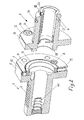
- einen zweiteiligen Werkzeughalter mit einge- setztem Drehstahl, teilweise im Schnitt,
- Fig.2
- den Werkzeughalter gemäss
Fig. 1 mit ge- trennten Teilen,
- Fig.1
- a two-part tool holder with inserted turning steel, partly in section,
- Fig.2
- according to the tool holder
Fig. 1 with separate parts,
Der in den Figuren gezeigte Werkzeughalter besteht aus zwei Teilen: einem maschinenseitigen Basishalter (VDI-Halter) 1 mit einem Zylinderschaft 2 zum Einsetzen in eine Aufnahme des Schlittens bzw. Revolvers eines Drehautomaten und einer werkzeugseitigen Spannzangenhalter 3, in welche eine Spannzange 4 eingesetzt werden kann.The tool holder shown in the figures consists of two parts: a machine-side base holder (VDI holder) 1 with a
Der Basishalter (VDI) weist werkzeugseitig einen Flansch 5 auf, in dessen Stirnseite eine konzentrische Ausnehmung 6 vorgesehen ist. In der Ausnehmung ist ein Justierring 7 angeordnet, dessen Aussendurchmesser geringfügig kleiner ist als der Innendurchmesser der Ausnehmung. Der Justierring wird mit zwei axialen Feststellschrauben 9 in der Ausnehmung gehalten.The base holder (VDI) has on the tool side a
Im Flansch sind in radialer Richtung zwei um 90° versetzte Justierschrauben 10 und zwei jeweils um weitere 90° versetzte Kugeldruckstücke 11 angeordnet. Die Justierschrauben drücken auf die Mantelfläche, und die Kugeldruckstücke greifen in eine Quernut ein. Die Quernut verhindert ein Verdrehen des Ringes 7 beim Festziehen des Spannzangenhalters.In the flange two offset by 90 °
Innerhalb des Justierringes ist im Flansch 5 ein axial gerichteter Justierstift 8 angeordnet, der dazu dient, die Werkzeugaufnahme nach der Voreinstellung in einem Basishalter (VDI) zu fixieren. Dadurch wird erreicht, dass die Spitzenhöhe des Werkzeugs nach dem Verschrauben mit dem Basishalter in der Maschine wieder stimmt.Within the adjusting ring an axially directed adjusting
Der Spannzangenhalter ist maschinenseitig mit einem Flansch 12 versehen, der seinerseits an seiner Stirnseite einen vorspringenden Passzylinder 13 aufweist. Der Passzylinder besitzt an der Stelle, die beim Zusammenbau dem Justierstift gegenüber liegt, eine Ausnehmung 24 bis zur Stirnfläche des Flansches 12. Im Flansch sind vier Befestigungsschrauben 14 zum Festziehen am Basishalter vorgesehen. Im Übrigen besteht der Spannzangenhalter aus einem langgestreckten zylindrischen Teil 15 mit einer in der Nähe des werkzeugseitigen Endes angeordneten Ringnut 16 für den Eingriff der Pressbacken eines an sich bekannten Presswerkzeugs und einer zur Maschinenseite hin konisch verengten Aufnahmebohrung 17 zur Aufnahme einer Spannzange 4. Mittels einer radialen Feststellschraube 18 wird eine Bohrstange oder ein Schneidwerkzeug horizontal definiert festgezogen.The collet holder is provided on the machine side with a
Zum Justieren wird zunächst der Basishalter in den Drehmaschinenrevolver gespannt. Danach wird mit der Justiereinrichtung der Drehmaschine der Justierring mit den Justierschrauben 10 gegen den Gegendruck der jeweils gegenüberliegenden Kugeldruckstücke voreingestellt und mit den Feststellschrauben 9 fixiert. Auf diese Weise kann der Ring mit nur zwei Schrauben justiert werden.To adjust the base holder is first clamped in the lathe turret. Thereafter, with the adjusting device of the lathe of the adjusting ring with the adjusting
Sobald Ring justiert und mit Feststellschrauben befestigt ist, kann der Spannzangenhalter eingesetzt werden. Der Passzylinder positioniert den Spanzangenhalter zentrisch mittels des voreingestellten Justierringes des Basishalters und radial mittels des Justierstifts 8 in der Ausnehmung 24 im Flansch 12.Once the ring is adjusted and secured with locking screws, the collet holder can be used. The pass cylinder centrally positions the chip holder by means of the preset adjustment ring of the base holder and radially by means of the adjusting
Der Justierring 7 kann, auch wenn der Spannzangenhalter schon gespannt wurde nachjustiert werden. Dazu müssen die Feststellschrauben 9 des Justierringes durch die zwei Bohrungen im Spanzangenhalterflansch und die vier Befestigungsschrauben 14 des Spannzangenhalters gelöst werden. Danach kann der Justierringe mittels Messvorrichtung des Drehautomaten nachjustiert werden.The adjusting
Die in
Die Spannzange 4 besitzt entsprechend dem bekannten Stand der Technik eine zylindrische Bohrung 20 zur Aufnahme eines Schafts 21 eines Werkzeugs 22, beispielsweise eines Drehstahls, und einen Kopf mit einem Flansch 23 für den Ansatz der Pressbacken des Presswerkzeugs. Ihre maschinenseitige Aussenfläche ist entsprechend dem Konuswinkel der Aufnahmebohrung 17 konisch verjüngt.The
Als Konuswinkel bzw. Konizität wird in der vorliegenden Beschreibung der Öffnungswinkel des Konus d.h. der Winkel zwischen einander gegenüberliegenden Erzeugenden bzw. Mantellinien der konischen Fläche und ihrer Achse bezeichnet. Dieser Konuswinkel ist bei dem hier beschriebenen Ausführungsbeispiel kleiner als der sog. Selbsthemmungswinkel von ca. 5°, vorzugsweise kleiner als 2°.As the taper angle in the present specification, the opening angle of the cone i. the angle between opposing generatrices or generatrices of the conical surface and its axis denotes. This cone angle is smaller in the embodiment described here than the so-called. Self-locking angle of about 5 °, preferably less than 2 °.
Der erfindungsgemässe Werkzeughalter ist nicht auf Ausführungsformen beschränkt, bei denen der Spannzangenhalter koaxial mit dem Basishalter verbunden wird. Für Werkzeughalter, in denen das Werkzeug radial, d.h. mit seiner Achse senkrecht zur Aufnahme im Revolver, im Halter sitzt, ist die erfindungsgemässe Lösung mit einer zusätzlichen Schnittstelle in gleicher Weise einsetzbar.The inventive tool holder is not limited to embodiments in which the collet holder is connected coaxially with the base holder. For tool holders in which the tool is radially, i. with its axis perpendicular to the receptacle in the revolver, sits in the holder, the inventive solution with an additional interface in the same way can be used.
Claims (4)
Applications Claiming Priority (1)
| Application Number | Priority Date | Filing Date | Title |
|---|---|---|---|
| CH00583/09A CH700780A1 (en) | 2009-04-14 | 2009-04-14 | Toolholder. |
Publications (1)
| Publication Number | Publication Date |
|---|---|
| EP2241395A1 true EP2241395A1 (en) | 2010-10-20 |
Family
ID=41055184
Family Applications (1)
| Application Number | Title | Priority Date | Filing Date |
|---|---|---|---|
| EP10159849A Withdrawn EP2241395A1 (en) | 2009-04-14 | 2010-04-14 | Tool holder |
Country Status (3)
| Country | Link |
|---|---|
| US (1) | US20100257982A1 (en) |
| EP (1) | EP2241395A1 (en) |
| CH (1) | CH700780A1 (en) |
Cited By (2)
| Publication number | Priority date | Publication date | Assignee | Title |
|---|---|---|---|---|
| ITUB20159601A1 (en) * | 2015-12-18 | 2017-06-18 | Autor srl | TOOL MACHINE WITH SPINDLE ALIGNMENT DEVICE |
| FR3067271A1 (en) * | 2017-06-09 | 2018-12-14 | Autor srl | Machine tool with pin alignment device |
Families Citing this family (3)
| Publication number | Priority date | Publication date | Assignee | Title |
|---|---|---|---|---|
| US8807880B2 (en) | 2009-11-02 | 2014-08-19 | Kennametal Inc. | Toolholder coupling for high pressure coolant |
| US9314985B2 (en) | 2011-09-27 | 2016-04-19 | Kennametal Inc. | Coated pelletizing extrusion dies and method for making the same |
| US10065247B2 (en) * | 2016-01-21 | 2018-09-04 | Chin-Chiu Chen | Cutter fastening assembly and cutter holder for the same |
Citations (3)
| Publication number | Priority date | Publication date | Assignee | Title |
|---|---|---|---|---|
| EP0065659A1 (en) * | 1981-05-21 | 1982-12-01 | BENZ GmbH Werkzeug- und Maschinenbau KG | Quick-change tool holder, in particular for lathes |
| DE8814953U1 (en) * | 1988-12-01 | 1990-02-22 | Fietz, Manfred, 5093 Burscheid, De | |
| EP1291103A1 (en) * | 2001-09-11 | 2003-03-12 | Rego-Fix AG | Chuck |
Family Cites Families (7)
| Publication number | Priority date | Publication date | Assignee | Title |
|---|---|---|---|---|
| US3572197A (en) * | 1968-12-10 | 1971-03-23 | Devlieg Machine Co | Adjustable toolholder |
| SE7710383L (en) * | 1977-09-16 | 1979-03-17 | Granlund & Co Ab H | COMBINATION TOOL |
| DE3673634D1 (en) * | 1986-03-03 | 1990-09-27 | Dihart Ag | TOOL HOLDER. |
| US5032043A (en) * | 1990-06-28 | 1991-07-16 | T. M. Smith Tool International Corporation | Spindle adapter for tool holder with tool adjustment control |
| US5193825A (en) * | 1991-10-03 | 1993-03-16 | Jacobs Chuck Technology Corporation | Apparatus for adjusting the center of a collet |
| DE4404725A1 (en) * | 1994-02-16 | 1995-08-17 | Beck August Gmbh Co | Alignment adapter |
| US5771762A (en) * | 1994-04-29 | 1998-06-30 | Bissett; Kevin J. | Quick-coupling face-driver assembly of a rotary drive device and method for changing face drivers |
-
2009
- 2009-04-14 CH CH00583/09A patent/CH700780A1/en not_active Application Discontinuation
-
2010
- 2010-04-13 US US12/758,872 patent/US20100257982A1/en not_active Abandoned
- 2010-04-14 EP EP10159849A patent/EP2241395A1/en not_active Withdrawn
Patent Citations (3)
| Publication number | Priority date | Publication date | Assignee | Title |
|---|---|---|---|---|
| EP0065659A1 (en) * | 1981-05-21 | 1982-12-01 | BENZ GmbH Werkzeug- und Maschinenbau KG | Quick-change tool holder, in particular for lathes |
| DE8814953U1 (en) * | 1988-12-01 | 1990-02-22 | Fietz, Manfred, 5093 Burscheid, De | |
| EP1291103A1 (en) * | 2001-09-11 | 2003-03-12 | Rego-Fix AG | Chuck |
Cited By (2)
| Publication number | Priority date | Publication date | Assignee | Title |
|---|---|---|---|---|
| ITUB20159601A1 (en) * | 2015-12-18 | 2017-06-18 | Autor srl | TOOL MACHINE WITH SPINDLE ALIGNMENT DEVICE |
| FR3067271A1 (en) * | 2017-06-09 | 2018-12-14 | Autor srl | Machine tool with pin alignment device |
Also Published As
| Publication number | Publication date |
|---|---|
| US20100257982A1 (en) | 2010-10-14 |
| CH700780A1 (en) | 2010-10-15 |
Similar Documents
| Publication | Publication Date | Title |
|---|---|---|
| EP1932607B1 (en) | Workpiece holder for exact positioning on a clamping chuck and clamping device with a chuck and workpiece holder positioned exactly thereon | |
| EP0687516A1 (en) | Combination tool | |
| CH656080A5 (en) | TURNING TOOL FOR FINISHING SHAFTS, PINS, TUBES. | |
| WO2011015259A1 (en) | Tool carrier having exchangeable tool holders, and tool holder | |
| DE2234389C3 (en) | Tool holder for non-rotating cutting tools on lathes | |
| EP2241395A1 (en) | Tool holder | |
| DE10219599B4 (en) | Tool clamping device | |
| DE3128121C2 (en) | Turning tool for machining the ends of shafts, journals, tubes and the like | |
| DE3929801C1 (en) | ||
| EP2101944A1 (en) | Machining tool | |
| DE3030908C2 (en) | ||
| DE3306137C2 (en) | ||
| DE3105537C2 (en) | Collet | |
| WO2009115222A1 (en) | Tool | |
| DE2059307B2 (en) | ||
| DE102006020807A1 (en) | Revolving tool carrier, for use in turning-milling machine for processing metal components, has region for connection to spindle, working region with processing implements and drill chuck receiiver | |
| DE2329064A1 (en) | Adapter sleeve holder for machine tool spindle noses - has locking collet and antirotation lock to hold cylindrical threaded tool holders | |
| DE102022107025A1 (en) | Tool holder | |
| DE3608141C2 (en) | ||
| WO1990008011A1 (en) | Device for machining workpieces, in particular tools | |
| DE102019114042A1 (en) | Tool adapter | |
| EP0443102A1 (en) | Mandrel with spindle/adaptor for tools | |
| DE3932805C2 (en) | ||
| DE3525610C2 (en) | ||
| DE202019102966U1 (en) | Tool adapter |
Legal Events
| Date | Code | Title | Description |
|---|---|---|---|
| PUAI | Public reference made under article 153(3) epc to a published international application that has entered the european phase |
Free format text: ORIGINAL CODE: 0009012 |
|
| AK | Designated contracting states |
Kind code of ref document: A1 Designated state(s): AT BE BG CH CY CZ DE DK EE ES FI FR GB GR HR HU IE IS IT LI LT LU LV MC MK MT NL NO PL PT RO SE SI SK SM TR |
|
| AX | Request for extension of the european patent |
Extension state: AL BA ME RS |
|
| 17P | Request for examination filed |
Effective date: 20110420 |
|
| 17Q | First examination report despatched |
Effective date: 20110927 |
|
| STAA | Information on the status of an ep patent application or granted ep patent |
Free format text: STATUS: THE APPLICATION IS DEEMED TO BE WITHDRAWN |
|
| 18D | Application deemed to be withdrawn |
Effective date: 20120208 |