EP2241370B1 - Mikromischer zum mischen von fluiden - Google Patents
Mikromischer zum mischen von fluiden Download PDFInfo
- Publication number
- EP2241370B1 EP2241370B1 EP10001579A EP10001579A EP2241370B1 EP 2241370 B1 EP2241370 B1 EP 2241370B1 EP 10001579 A EP10001579 A EP 10001579A EP 10001579 A EP10001579 A EP 10001579A EP 2241370 B1 EP2241370 B1 EP 2241370B1
- Authority
- EP
- European Patent Office
- Prior art keywords
- flow path
- fluid
- component
- introducing
- mixing
- Prior art date
- Legal status (The legal status is an assumption and is not a legal conclusion. Google has not performed a legal analysis and makes no representation as to the accuracy of the status listed.)
- Not-in-force
Links
- 239000012530 fluid Substances 0.000 title claims description 103
- 230000005484 gravity Effects 0.000 claims description 4
- 238000005304 joining Methods 0.000 claims description 4
- 238000007599 discharging Methods 0.000 claims 1
- 239000002245 particle Substances 0.000 description 18
- 238000006243 chemical reaction Methods 0.000 description 14
- 239000006185 dispersion Substances 0.000 description 6
- 238000000034 method Methods 0.000 description 6
- 239000000203 mixture Substances 0.000 description 4
- 230000000694 effects Effects 0.000 description 3
- 239000000463 material Substances 0.000 description 3
- 238000005260 corrosion Methods 0.000 description 2
- 230000007797 corrosion Effects 0.000 description 2
- 238000004904 shortening Methods 0.000 description 2
- 238000003786 synthesis reaction Methods 0.000 description 2
- YCKRFDGAMUMZLT-UHFFFAOYSA-N Fluorine atom Chemical compound [F] YCKRFDGAMUMZLT-UHFFFAOYSA-N 0.000 description 1
- 229910000990 Ni alloy Inorganic materials 0.000 description 1
- 238000004458 analytical method Methods 0.000 description 1
- 230000015572 biosynthetic process Effects 0.000 description 1
- 230000008602 contraction Effects 0.000 description 1
- 239000002178 crystalline material Substances 0.000 description 1
- 230000003247 decreasing effect Effects 0.000 description 1
- 238000005516 engineering process Methods 0.000 description 1
- 229910052731 fluorine Inorganic materials 0.000 description 1
- 239000011737 fluorine Substances 0.000 description 1
- 239000011521 glass Substances 0.000 description 1
- 239000007788 liquid Substances 0.000 description 1
- 238000012423 maintenance Methods 0.000 description 1
- 238000004519 manufacturing process Methods 0.000 description 1
- 229910052751 metal Inorganic materials 0.000 description 1
- 239000002184 metal Substances 0.000 description 1
- 150000002739 metals Chemical class 0.000 description 1
- 238000012544 monitoring process Methods 0.000 description 1
- 239000004033 plastic Substances 0.000 description 1
- 229920001643 poly(ether ketone) Polymers 0.000 description 1
- 229920005989 resin Polymers 0.000 description 1
- 239000011347 resin Substances 0.000 description 1
- 239000007787 solid Substances 0.000 description 1
- 239000000126 substance Substances 0.000 description 1
- 230000001629 suppression Effects 0.000 description 1
- 238000011144 upstream manufacturing Methods 0.000 description 1
Images


Classifications
-
- B—PERFORMING OPERATIONS; TRANSPORTING
- B01—PHYSICAL OR CHEMICAL PROCESSES OR APPARATUS IN GENERAL
- B01F—MIXING, e.g. DISSOLVING, EMULSIFYING OR DISPERSING
- B01F25/00—Flow mixers; Mixers for falling materials, e.g. solid particles
- B01F25/40—Static mixers
- B01F25/44—Mixers in which the components are pressed through slits
- B01F25/441—Mixers in which the components are pressed through slits characterised by the configuration of the surfaces forming the slits
- B01F25/4413—Mixers in which the components are pressed through slits characterised by the configuration of the surfaces forming the slits the slits being formed between opposed conical or cylindrical surfaces
-
- B—PERFORMING OPERATIONS; TRANSPORTING
- B01—PHYSICAL OR CHEMICAL PROCESSES OR APPARATUS IN GENERAL
- B01F—MIXING, e.g. DISSOLVING, EMULSIFYING OR DISPERSING
- B01F25/00—Flow mixers; Mixers for falling materials, e.g. solid particles
- B01F25/40—Static mixers
- B01F25/44—Mixers in which the components are pressed through slits
- B01F25/442—Mixers in which the components are pressed through slits characterised by the relative position of the surfaces during operation
- B01F25/4421—Mixers in which the components are pressed through slits characterised by the relative position of the surfaces during operation the surfaces being maintained in a fixed position, spaced from each other, therefore maintaining the slit always open
-
- B—PERFORMING OPERATIONS; TRANSPORTING
- B01—PHYSICAL OR CHEMICAL PROCESSES OR APPARATUS IN GENERAL
- B01F—MIXING, e.g. DISSOLVING, EMULSIFYING OR DISPERSING
- B01F33/00—Other mixers; Mixing plants; Combinations of mixers
- B01F33/30—Micromixers
- B01F33/301—Micromixers using specific means for arranging the streams to be mixed, e.g. channel geometries or dispositions
- B01F33/3011—Micromixers using specific means for arranging the streams to be mixed, e.g. channel geometries or dispositions using a sheathing stream of a fluid surrounding a central stream of a different fluid, e.g. for reducing the cross-section of the central stream or to produce droplets from the central stream
-
- B—PERFORMING OPERATIONS; TRANSPORTING
- B01—PHYSICAL OR CHEMICAL PROCESSES OR APPARATUS IN GENERAL
- B01F—MIXING, e.g. DISSOLVING, EMULSIFYING OR DISPERSING
- B01F33/00—Other mixers; Mixing plants; Combinations of mixers
- B01F33/30—Micromixers
- B01F33/301—Micromixers using specific means for arranging the streams to be mixed, e.g. channel geometries or dispositions
- B01F33/3012—Interdigital streams, e.g. lamellae
Definitions
- the present invention relates to a fluid mixer capable of performing a process of mixing and chemical reactions of fluid such as liquid or gas on a scale of less than 1 mm in width of a flow path.
- fluid mixers In recent years, in a chemical synthesis or chemical analysis field, fluid mixers have been used which are made up of a flow path of several tens to several hundred ⁇ m manufactured by microfabrication technology with the aim of shortening time for mixing and reactions.
- the fluid mixers of this kind are called micro mixers or micro reactors.
- the micro mixer has a short characteristic length of a flow path and a small Reynolds number which is a non-dimensional number indicating a ratio between inertial force and viscous force in a fluid and, therefore, flow becomes a layer stream.
- a small Reynolds number which is a non-dimensional number indicating a ratio between inertial force and viscous force in a fluid and, therefore, flow becomes a layer stream.
- EP 1762298 A1 discloses a micro reactor in which a plurality of nozzles for two different fluids are arranged on a circumference to form multilayer streams of which the two fluids alternately flow and widths of the multilayer streams are reduced towards downstream, namely, a center of the reactor.
- U.S. Patent No. 7579191B1 discloses a structure in which fluid not contributory to reactions is placed between an internal wall of a micro reactor and a reaction fluid to produce particles.
- U.S Patent Publication No. 2007-0291581 A1 discloses a structure in which a check-valve is provided between an introducing flow path of a reaction fluid and a portion for fluid joining and mixing.
- Purposes to produce particles by using a micro reactor are various but one of the purposes is to produce high-quality particles by uniformly controlling conditions for reactions for producing particles to rapidly mix a plurality of fluids.
- micro reactor disclosed in U.S. Patent No. 7579191B1 has also a problem in that, though adhesion of produced particles can be suppressed, due to mixing of fluids not contributory to reactions, control on uniform reactions is difficult.
- micro reactors disclosed in U.S. Patent No. 7579191B1 and U.S Patent Publication No. 2007-0291581A1 are configured to perform mixing by reducing a characteristic length of the flow paths for mixing fluids, a shape to be divided and/ or dimensions to shorten a mixing distance. Therefore, there is also a problem that mixing efficiency depends on dimensions of the flow path and the improvement of mixing speed without being limited by dimensions of the flow path is difficult.
- US 2004/052158 A1 discloses methods and apparatus for high-shear mixing and reacting of materials.
- the present invention is invented and it is an object of the present invention to rapidly mix fluids and to avoid clogging of a flow path caused by particles produced through the mixing process of fluids.
- a first embodiment of a fluid mixer of the present invention will be described with reference to Figs. 1 to 5 .
- a first embodiment of a fluid mixer comprises at least three components including an introducing component 1 having a bore, a cylindrical component 2 inserted into the bore of the introducing component 1 and comprises a cylindrical section 51 and a conical section 52 projecting from a bottom of the cylindrical section 51, and a mixing component 3 on which the introducing component 1 and cylindrical component 2 are fixed.
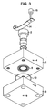
- the introducing component 1 is provided with a first introducing flow path 4 and a second supplying flow path 5 as shown in Fig. 3 .
- the second supplying flow path 5 comprises a plurality of radially extending flow passages outlets of which are opened in the bore of the introducing component 1 and inlets of which are opened in a second distributing flow path 8 which is described later.
- the outlets of the radially extending flow passages of the second supplying flow path 5 have a width which is substantially identical with a distance between adjacent radially extending flow passages.
- the cylindrical component 2 is provided with a first distributing flow path 6.
- the first distributing flow path 6 comprises an annular recess formed around the cylindrical component 2.
- the mixing component 3 is provided with a second introducing flow path 7, the second distributing flow path 8, and a discharge flow path 9 to discharge mixed fluid to a container or the like.
- the second introducing flow path 7 is communicated with the second distributing flow path 8.
- the second distributing flow path 8 comprises an annular recess formed on the mixing component 3 as shown in Fig. 2 .
- the second distributing flow path 8 functions as a temporary pool for second fluid introduced from the second introducing flow path 7 and equally distributes the second fluid into the radially extending flow passages of the second supplying flow path 5.
- O-rings 12 and 13 are respectively arranged in the first distributing flow path 6 and the second distributing flow path 8.
- the first introducing flow path 4 is communicated with the first distributing flow path 6.
- the first distributing flow path 6 functions as a temporary pool for first fluid introduced from the first introducing flow path 4 and uniformly distribute the first fluid into a first supplying flow path 10 (described later) .
- the first distributing flow path 6 is formed by a circular clearance between the bore of the introducing component 1 and the cylindrical section 51 of the cylindrical component 2 which occurs by constructing a portion of the cylindrical section 51 corresponding to the first distributing flow path 6 so as to have a smaller diameter than the other portions of the cylindrical section 51.
- a diameter of the cylindrical section 51 of the cylindrical component 2 positioned above the first distributing flow path 6 is approximately the same as an internal diameter of the bore of the introducing component 1.
- a center of an axis of the cylindrical section 51 of the cylindrical component 2 positioned below the first distributing flow path 6 is the same as a center of an axis of the cylindrical section 51 of the cylindrical component 2 positioned above the first distributing flow path 6 and a diameter of the cylindrical section 51 of the cylindrical component 2 positioned below the first distributing flow path 6 is slightly smaller than that of the cylindrical section 51 of the cylindrical component 2 above the first distributing flow path 6. Moreover, a diameter of the bore of the introducing component 1 is approximately the same length as in its upper and lower portions.
- the first annular supplying flow path 10 extending downwardly from the first distributing flow path 6 is formed between the introducing component 1 and the cylindrical section 51 of the cylindrical component 2 positioned below the first distributing flow path 6, due to a difference in diameter of the cylindrical component 2. That is, the diameter of a portion of the cylindrical component 2 in which a first fluid flows is made to be longer than that of a portion of the cylindrical component 2 in which the first distributing flow path 6 is formed and is made to be shorter than the diameter of a portion of the cylindrical component 2 in a direction opposite to a gravity direction from the portion of the cylindrical component 2 in which the first distributing flow path 6 is formed.
- the first supplying flow path 10 be an annular flow path having an uniform thickness of several tens to several hundred ⁇ m, which can provide an equal flow field of a fluid by the whole circumference.
- a conical recess is formed in the mixing component 3 and the conical recess has a conical angle smaller than that of the conical section 52 of the cylindrical component 2.
- the conical section 52 extends in the conical recess of the mixing component 3 and a mixing path 11 is formed between the conical recess and the conical section 52 of the cylindrical component 2.
- the cylindrical component 2 is fixed to the introducing component 1 by a cylinder retainer 14, a fixing screw 15, and a supporting member 16.
- First fluid introduced from the first introducing flow path 4 is distributed by the first distributing flow path 6 over whole circumference of the cylindrical component 2 and then passes through the first supplying flow path 10.
- second fluid introduced from the second introducing flow path 7 is distributed by the second distributing flow path 8 in a concentric manner with respect to the whole circumference of the cylindrical component 2 and passes through the second supplying flow path 5.
- the first fluid and the second fluid join together at a joining part 40 and then are introduced into the mixing flow path 11.
- the first and second fluids are alternately placed on the circumference of the cylindrical component 2 in a manner corresponding to the number of the radially extending passages of the second supplying flow path 5.
- Mixing time by dispersion is determined by an inter-fluid distance 17 being a characteristic length in a dispersion direction. Therefore, as is apparent from Figs. 5B and 5C , it is made possible to shorten the mixing time by decreasing the inter-fluid distances 19 and 21 in the mixing flow path 11.
- the dispersion mixing time is proportional to the square of the distance, and therefore, if the inter-fluid distance become one half (1/2), the mixing time is considered to be about a quarter (1/4).
- the diameter of the discharge flow path 9 is reduced to about one-third (1/3) or less (mixing time: one-ninth (1/9)) relative to the diameter of the cylindrical section 51 of the cylindrical component 2 in the joining part 40 of the first and second supplying flow paths 10 and 5.
- a cross sectional area of the mixing flow path 11 is gradually widened from the joining part 40 to the discharge flow path 9.
- the cross sectional area of the mixing flow path 11 may be approximately constant between the joining part 40 and the discharge flow path 9.
- a minimum dimension portion in a mixing flow path is critical when the fluid contains particles or is producing particles.
- the minimum dimension portion in the mixing flow path 11 is gradually expanded towards downstream (18 in Fig. 5A , 20 in Fig. 5B and 22 in Fig. 5C ) and there is no throat portion in the mixing flow path 11. With this structure, it is possible to prevent occurrence of clogging of the mixing flow path 11 by solid particles.
- the minimum dimension portion 18 of the mixing flow path 11 (distance between the introducing component 1 and the cylindrical section 51 of the cylindrical component 2) in the joining part 40 and in the section taken along the line VA-VA in Fig. 4 is equal to or smaller than the width of each of the radially extending passages of the second supplying flow path 5 and the minimum dimension portion 18 has an approximately constant width over the whole circumference.
- the diameter of the cylindrical section 52 of the cylindrical component 2 in the joining part 40 is made larger than the diameter of the discharge flow path 9 and the cross sectional area of the mixing flow path 11 is made constant or is made gradually expanded towards downstream of the fluids. Therefore, it is necessary to make the minimum dimension portion 18 in the cross section taken along line VA-VA' small as much as possible relative to the diameter of the cylindrical section 52 of the cylindrical component 2.
- a method is employed in which a clearance is formed by the difference in diameter between an internal diameter of the bore of the introducing component 1 and an external diameter of the cylindrical component 2.
- annular flow path can be formed accurately in which the difference in diameter between the bore of the introducing component 1 and the cylindrical component 2 and the central axis of the introducing component 1 coincides with that of the cylindrical component 2. Also, a surface area of the first introducing flow path 4 can be increased by the annular flow path being thus formed, and therefore, the efficiency of the temperature control of the fluid can be improved.
- the cylindrical component 2 can be easily removed by handling the cylinder retainer 14 and the fixing screw 15, and therefore, it becomes possible to open the mixing flow path 11. This enables easy work for checking the state of the mixing flow path 11 and its easy maintenance.
- Materials making up the above configuration are allowed to be selected from various metals such as highly corrosion resistant stainless in particular, corrosion-resistant nickel alloy, crystalline material such as glass, and plastic such as a fluorine resin or polyether ketone, depending on property, corrosiveness, exothermicity of reactions of the target row material.
- metals such as highly corrosion resistant stainless in particular, corrosion-resistant nickel alloy, crystalline material such as glass, and plastic such as a fluorine resin or polyether ketone, depending on property, corrosiveness, exothermicity of reactions of the target row material.
- multilayer streams are formed in which two fluids are alternately placed in the circumference direction of the cylindrical component 2.
- This multilayer stream due to contraction of the length of the circumference occurring when the stream flows through the conical mixing flow path, reduces a characteristic length of the dispersion mixing, which provides high mixing property.
- the distance between the inner and outer surfaces being the minimum interval of the conical flow path becomes gradually larger and, there is no throat portion, which enables the suppression of the clogging caused by produced particles.
- annular flow having a uniform and thin pattern is formed and a surface area of a flow path is increased, controllability of temperature is enhanced. Moreover, owing to uniform flow of the fluid through a narrow flow path, neither local backflow nor stagnation occurs before and after the joining part, which prevents the clogging in the flow path.
- the inside of the mixing flow path can be easily checked and cleaned by detaching the cylindrical component, which forms an inner face of the flow path, toward its upstream side.
- the second embodiment of the fluid mixer has a structure in which an introducing component plate 23 is added between the introducing component 1 and the mixing component 3 of the first embodiment.
- the introducing component 1 is provided with a first introducing flow path 4, a second introducing flow path 24, a second distributing flow path 25 and a second supplying flow path 5.
- the second distributing flow path 25 comprises an annular recess formed around the bore of the introducing component 1.
- the second introducing flow path 24 is communicated with the second distributing flow path 25.
- the cylindrical component 2 is provided with a first distributing flow path 6.
- the introducing component plate 23 is provided with a third supplying flow path 26. Similar to the second supplying flow path 5, the third supplying flow path 26 comprises a plurality of radially extending flow passages outlets of which are opened in the bore of the introducing component 1 and inlets of which are opened in a third distributing flow path 28 described later.
- the mixing component 3 is provided with a third introducing flow path 27, the third distributing flow path 28 communicated with the third introducing flow path 27, and the discharge flow path 9.
- the introducing component plate 23 is formed with a circular hole having the same diameter as that of the bore of the introducing component 1.
- the introducing component plate 23 is fixed to the introducing component 1 and the mixing component 3 by means of positioning pins etc. (not shown) so that a central axis of the circular hole coincides with that of the cylindrical component 2, and the cylindrical component 2 extends into the circular hole.
- the second distributing flow path 25 and third distributing flow path 28 are annular flow paths and distribute the second and third fluids so that the first, second, and third fluids have approximately the same fluid width.
- the second and third distributing flow paths 25 and 28 distribute the second and third fluids so that the first, second, and third fluids have the same numbers of widths of fluids.
- a third embodiment of the fluid mixer will be described with reference to Fig. 7 .
- the third embodiment differs from the first embodiment in shape of the mixing flow path.
- a mixing flow path 31 is constructed so that a cross sectional area of the mixing flow path 31 in a horizontal direction (approximately perpendicular to a gravity direction) is approximately constant from the joining part 40 to the discharge flow path 9.
- an average flow rate becomes constant in every cross section of the mixing flow path 31, which can reduce the possibility of the occurrence of stagnation in the mixing flow path 31 and concentration of force of the fluids mixed locally.
- reaction between fluids becomes stable and particles being produced therein are liable to become constant in size. Further, it becomes possible to prevent that the produced particles adhere to the mixing flow path 11 and discharge flow path 9 to clog them.
Landscapes
- Chemical & Material Sciences (AREA)
- Dispersion Chemistry (AREA)
- Chemical Kinetics & Catalysis (AREA)
- Physical Or Chemical Processes And Apparatus (AREA)
Claims (7)
- Fluidmischer zum Mischen eines ersten und eines zweiten Fluids, umfassend:eine Einführkomponente (1) mit einer Bohrung;eine zylindrische Komponente (2), die in die Bohrung der Einführkomponente (1) eingepasst ist und einen zylindrischen Abschnitt (51) und einen von einer Unterseite des zylindrischen Abschnitts (51) abstehenden konischen Abschnitt (52) umfasst;eine Mischkomponente (3), die eine konische Aussparung aufweist und auf der die Einführkomponente (1) und die zylindrische Komponente (2) gehalten sind;einen ersten Einführströmungspfad (4) zum Entgegennehmen des ersten Fluids;einen ersten Verteilungsströmungspfad (6) zum Verteilen des von dem ersten Einführströmungspfad (4) eingeführten ersten Fluids über den ganzen Umfang der zylindrischen Komponente (2);einen zweiten Einführströmungspfad (7) zum Entgegennehmen des zweiten Fluids;einen zu der zylindrischen Komponente (2) konzentrischen ringförmigen zweiten Verteilungsströmungspfad (8) zum Verteilen des von dem zweiten Einführströmungspfad (7) eingeführten zweiten Fluids, so dass das erste Fluid und das zweite Fluid in Umfangsrichtung alternierend angeordnet sind;einen Verbindungsteil (40), um das von dem ersten Verteilungsströmungspfad (6) zugeführte erste Fluid und das von dem zweiten Verteilungsströmungspfad (8) zugeführte zweite Fluid zu verbinden;einen Mischströmungspfad (11), der zwischen dem konischen Abschnitt (52) der zylindrischen Komponente (2) und der konischen Aussparung der Mischkomponente (3) gebildet ist, zum Mischen des ersten und des zweiten Fluids, wobei die Querschnittsfläche des Mischströmungspfads (11) in einer Richtung senkrecht zur Gravitationsrichtung konstant ist oder in der Strömungsrichtung zunimmt; undeinen Abgabeströmungspfad (9) zum Abgeben von gemischtem Fluid aus dem dem Mischströmungspfad (11) zugeführten ersten und zweiten Fluid.
- Fluidmischer nach Anspruch 1, wobei der erste Einführströmungspfad (4) in der Einführkomponente (1) vorgesehen ist, der erste Verteilungsströmungspfad (6) in der zylindrischen Komponente (2) vorgesehen ist, und der zweite Einführströmungspfad (7), der Verbindungsteil (40), der Mischströmungspfad (11) und der Abgabeströmungspfad (9) in der Mischkomponente (3) vorgesehen sind.
- Fluidmischer nach Anspruch 1, wobei der zweite Verteilungsströmungspfad (8) dazu ausgelegt ist, das zweite Fluid so zu verteilen, dass die Breite des zweiten Fluids die gleiche wird wie die des ersten Fluids.
- Fluidmischer nach Anspruch 1, wobei eine Querschnittsfläche des Verbindungsteils (40) in einer Richtung senkrecht zur Gravitationsrichtung im Wesentlichen gleich der des Abgabeströmungspfads (9) ist.
- Fluidmischer nach Anspruch 2, wobei die zylindrische Komponente (2) mit einem ersten Zuführströmungspfad (10) für das erste Fluid versehen ist, wobei der Durchmesser eines Teils der zylindrischen Komponente (2), in dem der erste Zuführströmungspfad (10) vorgesehen ist, größer als der Durchmesser eines Teils der zylindrischen Komponente (2) ist, in dem der erste Verteilungsströmungspfad (6) vorgesehen ist.
- Fluidmischer nach Anspruch 2, ferner umfassend eine Einführkomponentenplatte (23), die zwischen der Einführkomponente (1) und der Mischkomponente (3) vorgesehen ist, wobei die Mischkomponente (3) mit einem dritten Einführströmungspfad (27) für ein drittes Fluid und mit einem dritten Verteilungsströmungspfad (28) zum Verteilen des von dem dritten Einführströmungspfad (27) eingeführten dritten Fluids versehen ist, und wobei die Einführkomponentenplatte (23) mit einem dritten Zuführströmungspfad (26) gebildet ist, der mehrere radial verlaufende Strömungspassagen aufweist, die Auslässe zur Bohrung der Einführkomponente (1) und Einlässe in den dritten Verteilungsströmungspfad (28) aufweisen.
- Fluidmischer nach Anspruch 6, wobei der zweite Verteilungsströmungspfad (8) und der dritte Verteilungsströmungspfad (28) dazu ausgelegt sind, das zweite und das dritte Fluid so zu verteilen, dass das erste Fluid, das zweite Fluid und das dritte Fluid die gleiche Breite haben.
Applications Claiming Priority (1)
| Application Number | Priority Date | Filing Date | Title |
|---|---|---|---|
| JP2009099514A JP2010247071A (ja) | 2009-04-16 | 2009-04-16 | 流体混合器 |
Publications (3)
| Publication Number | Publication Date |
|---|---|
| EP2241370A2 EP2241370A2 (de) | 2010-10-20 |
| EP2241370A3 EP2241370A3 (de) | 2010-11-10 |
| EP2241370B1 true EP2241370B1 (de) | 2012-08-29 |
Family
ID=42270553
Family Applications (1)
| Application Number | Title | Priority Date | Filing Date |
|---|---|---|---|
| EP10001579A Not-in-force EP2241370B1 (de) | 2009-04-16 | 2010-02-16 | Mikromischer zum mischen von fluiden |
Country Status (3)
| Country | Link |
|---|---|
| US (1) | US8287179B2 (de) |
| EP (1) | EP2241370B1 (de) |
| JP (1) | JP2010247071A (de) |
Families Citing this family (4)
| Publication number | Priority date | Publication date | Assignee | Title |
|---|---|---|---|---|
| FR2993791B1 (fr) * | 2012-07-27 | 2014-07-11 | Eveon | Distributeur fluidique et dispositif de reconstitution in situ et d'administration |
| USD754765S1 (en) * | 2014-04-16 | 2016-04-26 | Nimatic Aps | Fluid mixer |
| JP6508629B2 (ja) * | 2015-11-16 | 2019-05-08 | 株式会社プリンシプル | 微細気泡発生装置 |
| US20250114764A1 (en) * | 2022-09-16 | 2025-04-10 | M. Technique Co., Ltd. | Microreactor |
Family Cites Families (14)
| Publication number | Priority date | Publication date | Assignee | Title |
|---|---|---|---|---|
| GB191315774A (en) * | 1912-09-26 | 1914-03-05 | Wilhelm Gotthilf Schroeder | Improvements in or relating to Devices for Mixing Emulsions. |
| FR461782A (fr) | 1913-08-08 | 1914-01-10 | Des Anciens Etablissements Hotchkiss Et Cie | Perfectionnements apportés aux fusils automatiques |
| US2965362A (en) * | 1957-11-13 | 1960-12-20 | Ingbuero Dipl Ing Friedrich He | Device for mixing and homogenizing |
| US3540474A (en) * | 1968-04-01 | 1970-11-17 | Beckman Instruments Inc | Rapid mixer |
| FI98892C (fi) * | 1994-11-15 | 1997-09-10 | Turun Asennusteam Oy | Polymeerien liuotusmenetelmä ja -laite |
| AUPO129096A0 (en) * | 1996-07-26 | 1996-08-22 | Boc Gases Australia Limited | Oxygen dissolver for pipelines or pipe outlets |
| WO2004025260A2 (en) * | 2002-09-11 | 2004-03-25 | Kreido Laboratories | Methods and apparatus for high-shear mixing and reacting of materials |
| JP4407177B2 (ja) | 2003-05-30 | 2010-02-03 | 富士フイルム株式会社 | マイクロリアクターを用いた反応方法 |
| DE502005005027D1 (de) | 2004-02-17 | 2008-09-25 | Ehrfeld Mikrotechnik Bts Gmbh | Mikromischer |
| JP4339163B2 (ja) * | 2004-03-31 | 2009-10-07 | 宇部興産株式会社 | マイクロデバイスおよび流体の合流方法 |
| GB0418447D0 (en) * | 2004-08-19 | 2004-09-22 | Advanced Phytonics Ltd | Process for preparing particles and apparatus |
| JP4715403B2 (ja) | 2005-09-08 | 2011-07-06 | 株式会社日立プラントテクノロジー | マイクロ化学反応装置 |
| JP4592644B2 (ja) * | 2006-06-02 | 2010-12-01 | 東レエンジニアリング株式会社 | マイクロリアクタ |
| JP5030520B2 (ja) * | 2006-09-29 | 2012-09-19 | 富士フイルム株式会社 | 流体混合方法及びマイクロデバイス |
-
2009
- 2009-04-16 JP JP2009099514A patent/JP2010247071A/ja active Pending
-
2010
- 2010-02-16 EP EP10001579A patent/EP2241370B1/de not_active Not-in-force
- 2010-02-18 US US12/708,070 patent/US8287179B2/en not_active Expired - Fee Related
Also Published As
| Publication number | Publication date |
|---|---|
| US8287179B2 (en) | 2012-10-16 |
| EP2241370A3 (de) | 2010-11-10 |
| EP2241370A2 (de) | 2010-10-20 |
| JP2010247071A (ja) | 2010-11-04 |
| US20100265786A1 (en) | 2010-10-21 |
Similar Documents
| Publication | Publication Date | Title |
|---|---|---|
| US8551417B2 (en) | Reactor and reaction plant | |
| US8123398B2 (en) | Fluid-processing device | |
| EP1473077B1 (de) | Vorrichtung zur Mischung von Fluiden | |
| EP2241370B1 (de) | Mikromischer zum mischen von fluiden | |
| US6896401B2 (en) | Method and device for reducing byproducts in the mixture of educt streams | |
| EP1908514A2 (de) | Mikroreaktor | |
| EP2547428A1 (de) | Reaktiver statischer mischer | |
| US20100305356A1 (en) | Method for producing isocyanates | |
| US20150018575A1 (en) | Highly segregated jet mixer for phosgenation of amines | |
| US6415993B1 (en) | Device for the mixing and subsequent atomizing of liquids | |
| CN103052438A (zh) | 静态反应性射流混合机以及在胺-光气混合工艺过程中混合的方法 | |
| JP5013424B2 (ja) | マイクロチップ、マスターチップ | |
| US10232338B2 (en) | Micro-channel reactor | |
| JP2011115754A (ja) | 化学装置 | |
| JP2008114151A (ja) | 流体混合器及び混合要素部材 | |
| US20090253841A1 (en) | Method for producing chemicals | |
| JP6115930B2 (ja) | 多段分割流路型混合器 | |
| EP1762298B1 (de) | Mikroreaktor mit sektorgeformten Nuten für zwei Flüssigkeiten | |
| US20100051128A1 (en) | Fluid transport channel, fluid processing apparatus and fluid processing system | |
| CN102574095A (zh) | 流体处理装置及处理方法 | |
| EP2151274B1 (de) | Öffnungsstrahl-Injektionsreaktor | |
| WO2023147003A1 (en) | A microfluidic device for reacting a mixture contained within a laminar co-flowing concentric buffer | |
| KR20180065775A (ko) | 반응기 | |
| SU1122346A1 (ru) | Смеситель газа и жидкости дл охлаждени узлов печей | |
| WO2025084036A1 (ja) | 反応装置 |
Legal Events
| Date | Code | Title | Description |
|---|---|---|---|
| PUAI | Public reference made under article 153(3) epc to a published international application that has entered the european phase |
Free format text: ORIGINAL CODE: 0009012 |
|
| PUAL | Search report despatched |
Free format text: ORIGINAL CODE: 0009013 |
|
| 17P | Request for examination filed |
Effective date: 20100331 |
|
| AK | Designated contracting states |
Kind code of ref document: A2 Designated state(s): AT BE BG CH CY CZ DE DK EE ES FI FR GB GR HR HU IE IS IT LI LT LU LV MC MK MT NL NO PL PT RO SE SI SK SM TR |
|
| AX | Request for extension of the european patent |
Extension state: AL BA RS |
|
| AK | Designated contracting states |
Kind code of ref document: A3 Designated state(s): AT BE BG CH CY CZ DE DK EE ES FI FR GB GR HR HU IE IS IT LI LT LU LV MC MK MT NL NO PL PT RO SE SI SK SM TR |
|
| AX | Request for extension of the european patent |
Extension state: AL BA RS |
|
| RIC1 | Information provided on ipc code assigned before grant |
Ipc: B01F 13/00 20060101ALI20101001BHEP Ipc: B01J 19/00 20060101ALI20101001BHEP Ipc: B01F 5/06 20060101ALI20101001BHEP Ipc: B01F 5/04 20060101ALI20101001BHEP Ipc: B01F 5/00 20060101AFI20100706BHEP |
|
| GRAP | Despatch of communication of intention to grant a patent |
Free format text: ORIGINAL CODE: EPIDOSNIGR1 |
|
| RIC1 | Information provided on ipc code assigned before grant |
Ipc: B01F 5/06 20060101ALI20120201BHEP Ipc: B01J 19/00 20060101ALI20120201BHEP Ipc: B01F 13/00 20060101ALI20120201BHEP Ipc: B01F 5/00 20060101AFI20120201BHEP Ipc: B01F 5/04 20060101ALI20120201BHEP |
|
| GRAS | Grant fee paid |
Free format text: ORIGINAL CODE: EPIDOSNIGR3 |
|
| GRAA | (expected) grant |
Free format text: ORIGINAL CODE: 0009210 |
|
| AK | Designated contracting states |
Kind code of ref document: B1 Designated state(s): AT BE BG CH CY CZ DE DK EE ES FI FR GB GR HR HU IE IS IT LI LT LU LV MC MK MT NL NO PL PT RO SE SI SK SM TR |
|
| REG | Reference to a national code |
Ref country code: GB Ref legal event code: FG4D |
|
| REG | Reference to a national code |
Ref country code: CH Ref legal event code: EP |
|
| REG | Reference to a national code |
Ref country code: AT Ref legal event code: REF Ref document number: 572758 Country of ref document: AT Kind code of ref document: T Effective date: 20120915 |
|
| REG | Reference to a national code |
Ref country code: IE Ref legal event code: FG4D |
|
| REG | Reference to a national code |
Ref country code: DE Ref legal event code: R096 Ref document number: 602010002561 Country of ref document: DE Effective date: 20121025 |
|
| REG | Reference to a national code |
Ref country code: NL Ref legal event code: T3 |
|
| REG | Reference to a national code |
Ref country code: SE Ref legal event code: TRGR |
|
| REG | Reference to a national code |
Ref country code: AT Ref legal event code: MK05 Ref document number: 572758 Country of ref document: AT Kind code of ref document: T Effective date: 20120829 |
|
| REG | Reference to a national code |
Ref country code: LT Ref legal event code: MG4D Effective date: 20120829 |
|
| PG25 | Lapsed in a contracting state [announced via postgrant information from national office to epo] |
Ref country code: HR Free format text: LAPSE BECAUSE OF FAILURE TO SUBMIT A TRANSLATION OF THE DESCRIPTION OR TO PAY THE FEE WITHIN THE PRESCRIBED TIME-LIMIT Effective date: 20120829 Ref country code: FI Free format text: LAPSE BECAUSE OF FAILURE TO SUBMIT A TRANSLATION OF THE DESCRIPTION OR TO PAY THE FEE WITHIN THE PRESCRIBED TIME-LIMIT Effective date: 20120829 Ref country code: IS Free format text: LAPSE BECAUSE OF FAILURE TO SUBMIT A TRANSLATION OF THE DESCRIPTION OR TO PAY THE FEE WITHIN THE PRESCRIBED TIME-LIMIT Effective date: 20121229 Ref country code: AT Free format text: LAPSE BECAUSE OF FAILURE TO SUBMIT A TRANSLATION OF THE DESCRIPTION OR TO PAY THE FEE WITHIN THE PRESCRIBED TIME-LIMIT Effective date: 20120829 Ref country code: NO Free format text: LAPSE BECAUSE OF FAILURE TO SUBMIT A TRANSLATION OF THE DESCRIPTION OR TO PAY THE FEE WITHIN THE PRESCRIBED TIME-LIMIT Effective date: 20121129 Ref country code: LT Free format text: LAPSE BECAUSE OF FAILURE TO SUBMIT A TRANSLATION OF THE DESCRIPTION OR TO PAY THE FEE WITHIN THE PRESCRIBED TIME-LIMIT Effective date: 20120829 Ref country code: CY Free format text: LAPSE BECAUSE OF FAILURE TO SUBMIT A TRANSLATION OF THE DESCRIPTION OR TO PAY THE FEE WITHIN THE PRESCRIBED TIME-LIMIT Effective date: 20120829 |
|
| PG25 | Lapsed in a contracting state [announced via postgrant information from national office to epo] |
Ref country code: BE Free format text: LAPSE BECAUSE OF FAILURE TO SUBMIT A TRANSLATION OF THE DESCRIPTION OR TO PAY THE FEE WITHIN THE PRESCRIBED TIME-LIMIT Effective date: 20120829 Ref country code: LV Free format text: LAPSE BECAUSE OF FAILURE TO SUBMIT A TRANSLATION OF THE DESCRIPTION OR TO PAY THE FEE WITHIN THE PRESCRIBED TIME-LIMIT Effective date: 20120829 Ref country code: PT Free format text: LAPSE BECAUSE OF FAILURE TO SUBMIT A TRANSLATION OF THE DESCRIPTION OR TO PAY THE FEE WITHIN THE PRESCRIBED TIME-LIMIT Effective date: 20121231 Ref country code: GR Free format text: LAPSE BECAUSE OF FAILURE TO SUBMIT A TRANSLATION OF THE DESCRIPTION OR TO PAY THE FEE WITHIN THE PRESCRIBED TIME-LIMIT Effective date: 20121130 Ref country code: SI Free format text: LAPSE BECAUSE OF FAILURE TO SUBMIT A TRANSLATION OF THE DESCRIPTION OR TO PAY THE FEE WITHIN THE PRESCRIBED TIME-LIMIT Effective date: 20120829 |
|
| PG25 | Lapsed in a contracting state [announced via postgrant information from national office to epo] |
Ref country code: RO Free format text: LAPSE BECAUSE OF FAILURE TO SUBMIT A TRANSLATION OF THE DESCRIPTION OR TO PAY THE FEE WITHIN THE PRESCRIBED TIME-LIMIT Effective date: 20120829 Ref country code: ES Free format text: LAPSE BECAUSE OF FAILURE TO SUBMIT A TRANSLATION OF THE DESCRIPTION OR TO PAY THE FEE WITHIN THE PRESCRIBED TIME-LIMIT Effective date: 20121210 Ref country code: DK Free format text: LAPSE BECAUSE OF FAILURE TO SUBMIT A TRANSLATION OF THE DESCRIPTION OR TO PAY THE FEE WITHIN THE PRESCRIBED TIME-LIMIT Effective date: 20120829 Ref country code: CZ Free format text: LAPSE BECAUSE OF FAILURE TO SUBMIT A TRANSLATION OF THE DESCRIPTION OR TO PAY THE FEE WITHIN THE PRESCRIBED TIME-LIMIT Effective date: 20120829 Ref country code: EE Free format text: LAPSE BECAUSE OF FAILURE TO SUBMIT A TRANSLATION OF THE DESCRIPTION OR TO PAY THE FEE WITHIN THE PRESCRIBED TIME-LIMIT Effective date: 20120829 |
|
| PGFP | Annual fee paid to national office [announced via postgrant information from national office to epo] |
Ref country code: SE Payment date: 20130222 Year of fee payment: 4 |
|
| PG25 | Lapsed in a contracting state [announced via postgrant information from national office to epo] |
Ref country code: SK Free format text: LAPSE BECAUSE OF FAILURE TO SUBMIT A TRANSLATION OF THE DESCRIPTION OR TO PAY THE FEE WITHIN THE PRESCRIBED TIME-LIMIT Effective date: 20120829 Ref country code: PL Free format text: LAPSE BECAUSE OF FAILURE TO SUBMIT A TRANSLATION OF THE DESCRIPTION OR TO PAY THE FEE WITHIN THE PRESCRIBED TIME-LIMIT Effective date: 20120829 Ref country code: IT Free format text: LAPSE BECAUSE OF FAILURE TO SUBMIT A TRANSLATION OF THE DESCRIPTION OR TO PAY THE FEE WITHIN THE PRESCRIBED TIME-LIMIT Effective date: 20120829 |
|
| PGFP | Annual fee paid to national office [announced via postgrant information from national office to epo] |
Ref country code: NL Payment date: 20130227 Year of fee payment: 4 |
|
| PLBE | No opposition filed within time limit |
Free format text: ORIGINAL CODE: 0009261 |
|
| STAA | Information on the status of an ep patent application or granted ep patent |
Free format text: STATUS: NO OPPOSITION FILED WITHIN TIME LIMIT |
|
| PG25 | Lapsed in a contracting state [announced via postgrant information from national office to epo] |
Ref country code: BG Free format text: LAPSE BECAUSE OF FAILURE TO SUBMIT A TRANSLATION OF THE DESCRIPTION OR TO PAY THE FEE WITHIN THE PRESCRIBED TIME-LIMIT Effective date: 20121129 |
|
| PGFP | Annual fee paid to national office [announced via postgrant information from national office to epo] |
Ref country code: DE Payment date: 20130426 Year of fee payment: 4 |
|
| 26N | No opposition filed |
Effective date: 20130530 |
|
| REG | Reference to a national code |
Ref country code: DE Ref legal event code: R097 Ref document number: 602010002561 Country of ref document: DE Effective date: 20130530 |
|
| PG25 | Lapsed in a contracting state [announced via postgrant information from national office to epo] |
Ref country code: MC Free format text: LAPSE BECAUSE OF NON-PAYMENT OF DUE FEES Effective date: 20130228 |
|
| REG | Reference to a national code |
Ref country code: FR Ref legal event code: ST Effective date: 20131031 |
|
| REG | Reference to a national code |
Ref country code: IE Ref legal event code: MM4A |
|
| PG25 | Lapsed in a contracting state [announced via postgrant information from national office to epo] |
Ref country code: FR Free format text: LAPSE BECAUSE OF NON-PAYMENT OF DUE FEES Effective date: 20130228 Ref country code: IE Free format text: LAPSE BECAUSE OF NON-PAYMENT OF DUE FEES Effective date: 20130216 |
|
| PG25 | Lapsed in a contracting state [announced via postgrant information from national office to epo] |
Ref country code: MT Free format text: LAPSE BECAUSE OF FAILURE TO SUBMIT A TRANSLATION OF THE DESCRIPTION OR TO PAY THE FEE WITHIN THE PRESCRIBED TIME-LIMIT Effective date: 20120829 |
|
| REG | Reference to a national code |
Ref country code: DE Ref legal event code: R119 Ref document number: 602010002561 Country of ref document: DE |
|
| REG | Reference to a national code |
Ref country code: NL Ref legal event code: V1 Effective date: 20140901 |
|
| REG | Reference to a national code |
Ref country code: CH Ref legal event code: PL Ref country code: SE Ref legal event code: EUG |
|
| GBPC | Gb: european patent ceased through non-payment of renewal fee |
Effective date: 20140216 |
|
| PG25 | Lapsed in a contracting state [announced via postgrant information from national office to epo] |
Ref country code: LI Free format text: LAPSE BECAUSE OF NON-PAYMENT OF DUE FEES Effective date: 20140228 Ref country code: NL Free format text: LAPSE BECAUSE OF NON-PAYMENT OF DUE FEES Effective date: 20140901 Ref country code: CH Free format text: LAPSE BECAUSE OF NON-PAYMENT OF DUE FEES Effective date: 20140228 |
|
| PG25 | Lapsed in a contracting state [announced via postgrant information from national office to epo] |
Ref country code: SE Free format text: LAPSE BECAUSE OF NON-PAYMENT OF DUE FEES Effective date: 20140217 |
|
| REG | Reference to a national code |
Ref country code: DE Ref legal event code: R119 Ref document number: 602010002561 Country of ref document: DE Effective date: 20140902 |
|
| PG25 | Lapsed in a contracting state [announced via postgrant information from national office to epo] |
Ref country code: DE Free format text: LAPSE BECAUSE OF NON-PAYMENT OF DUE FEES Effective date: 20140902 Ref country code: GB Free format text: LAPSE BECAUSE OF NON-PAYMENT OF DUE FEES Effective date: 20140216 |
|
| PG25 | Lapsed in a contracting state [announced via postgrant information from national office to epo] |
Ref country code: SM Free format text: LAPSE BECAUSE OF FAILURE TO SUBMIT A TRANSLATION OF THE DESCRIPTION OR TO PAY THE FEE WITHIN THE PRESCRIBED TIME-LIMIT Effective date: 20120829 |
|
| PG25 | Lapsed in a contracting state [announced via postgrant information from national office to epo] |
Ref country code: TR Free format text: LAPSE BECAUSE OF FAILURE TO SUBMIT A TRANSLATION OF THE DESCRIPTION OR TO PAY THE FEE WITHIN THE PRESCRIBED TIME-LIMIT Effective date: 20120829 |
|
| PG25 | Lapsed in a contracting state [announced via postgrant information from national office to epo] |
Ref country code: MK Free format text: LAPSE BECAUSE OF FAILURE TO SUBMIT A TRANSLATION OF THE DESCRIPTION OR TO PAY THE FEE WITHIN THE PRESCRIBED TIME-LIMIT Effective date: 20120829 Ref country code: HU Free format text: LAPSE BECAUSE OF FAILURE TO SUBMIT A TRANSLATION OF THE DESCRIPTION OR TO PAY THE FEE WITHIN THE PRESCRIBED TIME-LIMIT; INVALID AB INITIO Effective date: 20100216 Ref country code: LU Free format text: LAPSE BECAUSE OF NON-PAYMENT OF DUE FEES Effective date: 20130216 |