EP2241361B1 - Système de filtration d'eau de plan de travail - Google Patents
Système de filtration d'eau de plan de travail Download PDFInfo
- Publication number
- EP2241361B1 EP2241361B1 EP10161996A EP10161996A EP2241361B1 EP 2241361 B1 EP2241361 B1 EP 2241361B1 EP 10161996 A EP10161996 A EP 10161996A EP 10161996 A EP10161996 A EP 10161996A EP 2241361 B1 EP2241361 B1 EP 2241361B1
- Authority
- EP
- European Patent Office
- Prior art keywords
- pressure vessel
- filter media
- media cartridge
- end cap
- cartridge
- Prior art date
- Legal status (The legal status is an assumption and is not a legal conclusion. Google has not performed a legal analysis and makes no representation as to the accuracy of the status listed.)
- Not-in-force
Links
- 238000001914 filtration Methods 0.000 title claims abstract description 230
- XLYOFNOQVPJJNP-UHFFFAOYSA-N water Substances O XLYOFNOQVPJJNP-UHFFFAOYSA-N 0.000 title abstract description 182
- 238000000034 method Methods 0.000 claims abstract description 23
- 238000007789 sealing Methods 0.000 claims description 25
- 238000006722 reduction reaction Methods 0.000 claims description 12
- 230000008901 benefit Effects 0.000 claims description 10
- 230000009467 reduction Effects 0.000 claims description 7
- 239000003638 chemical reducing agent Substances 0.000 claims description 5
- 238000013519 translation Methods 0.000 claims description 4
- 239000012092 media component Substances 0.000 claims description 2
- 238000009428 plumbing Methods 0.000 abstract description 29
- 238000000926 separation method Methods 0.000 abstract description 9
- 230000011664 signaling Effects 0.000 abstract description 3
- OKTJSMMVPCPJKN-UHFFFAOYSA-N Carbon Chemical compound [C] OKTJSMMVPCPJKN-UHFFFAOYSA-N 0.000 description 70
- 229910052799 carbon Inorganic materials 0.000 description 62
- 238000005374 membrane filtration Methods 0.000 description 32
- 239000012530 fluid Substances 0.000 description 21
- 230000008859 change Effects 0.000 description 10
- 230000002452 interceptive effect Effects 0.000 description 10
- 239000000126 substance Substances 0.000 description 10
- 238000012360 testing method Methods 0.000 description 10
- 239000012535 impurity Substances 0.000 description 9
- 239000012528 membrane Substances 0.000 description 8
- 235000014676 Phragmites communis Nutrition 0.000 description 6
- 239000003651 drinking water Substances 0.000 description 6
- 238000009434 installation Methods 0.000 description 6
- ORQBXQOJMQIAOY-UHFFFAOYSA-N nobelium Chemical compound [No] ORQBXQOJMQIAOY-UHFFFAOYSA-N 0.000 description 6
- 235000012206 bottled water Nutrition 0.000 description 5
- 238000004891 communication Methods 0.000 description 4
- 239000000356 contaminant Substances 0.000 description 4
- 238000011109 contamination Methods 0.000 description 4
- 230000008878 coupling Effects 0.000 description 4
- 238000010168 coupling process Methods 0.000 description 4
- 238000005859 coupling reaction Methods 0.000 description 4
- 238000013461 design Methods 0.000 description 4
- 238000011161 development Methods 0.000 description 4
- 230000018109 developmental process Effects 0.000 description 4
- 230000006872 improvement Effects 0.000 description 4
- 239000013049 sediment Substances 0.000 description 4
- 230000001580 bacterial effect Effects 0.000 description 3
- 230000002829 reductive effect Effects 0.000 description 3
- 230000004397 blinking Effects 0.000 description 2
- 238000009833 condensation Methods 0.000 description 2
- 230000005494 condensation Effects 0.000 description 2
- 238000010276 construction Methods 0.000 description 2
- 235000020188 drinking water Nutrition 0.000 description 2
- 230000009977 dual effect Effects 0.000 description 2
- 238000005516 engineering process Methods 0.000 description 2
- 230000001965 increasing effect Effects 0.000 description 2
- 239000002991 molded plastic Substances 0.000 description 2
- 230000036961 partial effect Effects 0.000 description 2
- 238000003825 pressing Methods 0.000 description 2
- 230000008569 process Effects 0.000 description 2
- 239000007921 spray Substances 0.000 description 2
- ZAMOUSCENKQFHK-UHFFFAOYSA-N Chlorine atom Chemical compound [Cl] ZAMOUSCENKQFHK-UHFFFAOYSA-N 0.000 description 1
- 206010011732 Cyst Diseases 0.000 description 1
- 241000588756 Raoultella terrigena Species 0.000 description 1
- 241000098700 Sarcocheilichthys parvus Species 0.000 description 1
- -1 Turbidity Substances 0.000 description 1
- 230000004913 activation Effects 0.000 description 1
- 239000000654 additive Substances 0.000 description 1
- 230000002411 adverse Effects 0.000 description 1
- 239000010425 asbestos Substances 0.000 description 1
- 230000000712 assembly Effects 0.000 description 1
- 238000000429 assembly Methods 0.000 description 1
- 239000006229 carbon black Substances 0.000 description 1
- 229910052801 chlorine Inorganic materials 0.000 description 1
- 239000000460 chlorine Substances 0.000 description 1
- 230000002860 competitive effect Effects 0.000 description 1
- 208000031513 cyst Diseases 0.000 description 1
- 238000002242 deionisation method Methods 0.000 description 1
- 238000012938 design process Methods 0.000 description 1
- 230000003292 diminished effect Effects 0.000 description 1
- 238000006073 displacement reaction Methods 0.000 description 1
- 238000004821 distillation Methods 0.000 description 1
- 238000005538 encapsulation Methods 0.000 description 1
- 230000002708 enhancing effect Effects 0.000 description 1
- 230000007613 environmental effect Effects 0.000 description 1
- 230000003203 everyday effect Effects 0.000 description 1
- 238000011010 flushing procedure Methods 0.000 description 1
- 238000003780 insertion Methods 0.000 description 1
- 230000037431 insertion Effects 0.000 description 1
- 230000003993 interaction Effects 0.000 description 1
- 238000005342 ion exchange Methods 0.000 description 1
- 230000000670 limiting effect Effects 0.000 description 1
- 239000007788 liquid Substances 0.000 description 1
- 230000007257 malfunction Effects 0.000 description 1
- 230000013011 mating Effects 0.000 description 1
- 150000002894 organic compounds Chemical class 0.000 description 1
- 239000004033 plastic Substances 0.000 description 1
- 238000011045 prefiltration Methods 0.000 description 1
- 230000001681 protective effect Effects 0.000 description 1
- 239000008213 purified water Substances 0.000 description 1
- 238000001223 reverse osmosis Methods 0.000 description 1
- 230000002441 reversible effect Effects 0.000 description 1
- 229910052895 riebeckite Inorganic materials 0.000 description 1
- 238000005549 size reduction Methods 0.000 description 1
- 239000007787 solid Substances 0.000 description 1
- 238000003860 storage Methods 0.000 description 1
- 230000003612 virological effect Effects 0.000 description 1
- 238000003466 welding Methods 0.000 description 1
Images


Classifications
-
- B—PERFORMING OPERATIONS; TRANSPORTING
- B01—PHYSICAL OR CHEMICAL PROCESSES OR APPARATUS IN GENERAL
- B01D—SEPARATION
- B01D29/00—Filters with filtering elements stationary during filtration, e.g. pressure or suction filters, not covered by groups B01D24/00 - B01D27/00; Filtering elements therefor
- B01D29/11—Filters with filtering elements stationary during filtration, e.g. pressure or suction filters, not covered by groups B01D24/00 - B01D27/00; Filtering elements therefor with bag, cage, hose, tube, sleeve or like filtering elements
- B01D29/114—Filters with filtering elements stationary during filtration, e.g. pressure or suction filters, not covered by groups B01D24/00 - B01D27/00; Filtering elements therefor with bag, cage, hose, tube, sleeve or like filtering elements arranged for inward flow filtration
-
- B—PERFORMING OPERATIONS; TRANSPORTING
- B01—PHYSICAL OR CHEMICAL PROCESSES OR APPARATUS IN GENERAL
- B01D—SEPARATION
- B01D29/00—Filters with filtering elements stationary during filtration, e.g. pressure or suction filters, not covered by groups B01D24/00 - B01D27/00; Filtering elements therefor
- B01D29/50—Filters with filtering elements stationary during filtration, e.g. pressure or suction filters, not covered by groups B01D24/00 - B01D27/00; Filtering elements therefor with multiple filtering elements, characterised by their mutual disposition
- B01D29/56—Filters with filtering elements stationary during filtration, e.g. pressure or suction filters, not covered by groups B01D24/00 - B01D27/00; Filtering elements therefor with multiple filtering elements, characterised by their mutual disposition in series connection
- B01D29/58—Filters with filtering elements stationary during filtration, e.g. pressure or suction filters, not covered by groups B01D24/00 - B01D27/00; Filtering elements therefor with multiple filtering elements, characterised by their mutual disposition in series connection arranged concentrically or coaxially
-
- B—PERFORMING OPERATIONS; TRANSPORTING
- B01—PHYSICAL OR CHEMICAL PROCESSES OR APPARATUS IN GENERAL
- B01D—SEPARATION
- B01D29/00—Filters with filtering elements stationary during filtration, e.g. pressure or suction filters, not covered by groups B01D24/00 - B01D27/00; Filtering elements therefor
- B01D29/60—Filters with filtering elements stationary during filtration, e.g. pressure or suction filters, not covered by groups B01D24/00 - B01D27/00; Filtering elements therefor integrally combined with devices for controlling the filtration
- B01D29/603—Filters with filtering elements stationary during filtration, e.g. pressure or suction filters, not covered by groups B01D24/00 - B01D27/00; Filtering elements therefor integrally combined with devices for controlling the filtration by flow measuring
-
- B—PERFORMING OPERATIONS; TRANSPORTING
- B01—PHYSICAL OR CHEMICAL PROCESSES OR APPARATUS IN GENERAL
- B01D—SEPARATION
- B01D29/00—Filters with filtering elements stationary during filtration, e.g. pressure or suction filters, not covered by groups B01D24/00 - B01D27/00; Filtering elements therefor
- B01D29/96—Filters with filtering elements stationary during filtration, e.g. pressure or suction filters, not covered by groups B01D24/00 - B01D27/00; Filtering elements therefor in which the filtering elements are moved between filtering operations; Particular measures for removing or replacing the filtering elements; Transport systems for filters
-
- B—PERFORMING OPERATIONS; TRANSPORTING
- B01—PHYSICAL OR CHEMICAL PROCESSES OR APPARATUS IN GENERAL
- B01D—SEPARATION
- B01D35/00—Filtering devices having features not specifically covered by groups B01D24/00 - B01D33/00, or for applications not specifically covered by groups B01D24/00 - B01D33/00; Auxiliary devices for filtration; Filter housing constructions
- B01D35/14—Safety devices specially adapted for filtration; Devices for indicating clogging
- B01D35/143—Filter condition indicators
-
- B—PERFORMING OPERATIONS; TRANSPORTING
- B01—PHYSICAL OR CHEMICAL PROCESSES OR APPARATUS IN GENERAL
- B01D—SEPARATION
- B01D35/00—Filtering devices having features not specifically covered by groups B01D24/00 - B01D33/00, or for applications not specifically covered by groups B01D24/00 - B01D33/00; Auxiliary devices for filtration; Filter housing constructions
- B01D35/30—Filter housing constructions
- B01D35/301—Constructions of two or more housings
-
- C—CHEMISTRY; METALLURGY
- C02—TREATMENT OF WATER, WASTE WATER, SEWAGE, OR SLUDGE
- C02F—TREATMENT OF WATER, WASTE WATER, SEWAGE, OR SLUDGE
- C02F9/00—Multistage treatment of water, waste water or sewage
- C02F9/20—Portable or detachable small-scale multistage treatment devices, e.g. point of use or laboratory water purification systems
-
- B—PERFORMING OPERATIONS; TRANSPORTING
- B01—PHYSICAL OR CHEMICAL PROCESSES OR APPARATUS IN GENERAL
- B01D—SEPARATION
- B01D2201/00—Details relating to filtering apparatus
- B01D2201/04—Supports for the filtering elements
- B01D2201/0415—Details of supporting structures
-
- B—PERFORMING OPERATIONS; TRANSPORTING
- B01—PHYSICAL OR CHEMICAL PROCESSES OR APPARATUS IN GENERAL
- B01D—SEPARATION
- B01D2201/00—Details relating to filtering apparatus
- B01D2201/30—Filter housing constructions
- B01D2201/301—Details of removable closures, lids, caps, filter heads
- B01D2201/304—Seals or gaskets
-
- B—PERFORMING OPERATIONS; TRANSPORTING
- B01—PHYSICAL OR CHEMICAL PROCESSES OR APPARATUS IN GENERAL
- B01D—SEPARATION
- B01D2201/00—Details relating to filtering apparatus
- B01D2201/40—Special measures for connecting different parts of the filter
- B01D2201/4015—Bayonet connecting means
-
- B—PERFORMING OPERATIONS; TRANSPORTING
- B01—PHYSICAL OR CHEMICAL PROCESSES OR APPARATUS IN GENERAL
- B01D—SEPARATION
- B01D2201/00—Details relating to filtering apparatus
- B01D2201/40—Special measures for connecting different parts of the filter
- B01D2201/4076—Anti-rotational means
-
- C—CHEMISTRY; METALLURGY
- C02—TREATMENT OF WATER, WASTE WATER, SEWAGE, OR SLUDGE
- C02F—TREATMENT OF WATER, WASTE WATER, SEWAGE, OR SLUDGE
- C02F1/00—Treatment of water, waste water, or sewage
- C02F1/001—Processes for the treatment of water whereby the filtration technique is of importance
-
- C—CHEMISTRY; METALLURGY
- C02—TREATMENT OF WATER, WASTE WATER, SEWAGE, OR SLUDGE
- C02F—TREATMENT OF WATER, WASTE WATER, SEWAGE, OR SLUDGE
- C02F1/00—Treatment of water, waste water, or sewage
- C02F1/28—Treatment of water, waste water, or sewage by sorption
- C02F1/283—Treatment of water, waste water, or sewage by sorption using coal, charred products, or inorganic mixtures containing them
-
- C—CHEMISTRY; METALLURGY
- C02—TREATMENT OF WATER, WASTE WATER, SEWAGE, OR SLUDGE
- C02F—TREATMENT OF WATER, WASTE WATER, SEWAGE, OR SLUDGE
- C02F1/00—Treatment of water, waste water, or sewage
- C02F1/44—Treatment of water, waste water, or sewage by dialysis, osmosis or reverse osmosis
- C02F1/444—Treatment of water, waste water, or sewage by dialysis, osmosis or reverse osmosis by ultrafiltration or microfiltration
-
- C—CHEMISTRY; METALLURGY
- C02—TREATMENT OF WATER, WASTE WATER, SEWAGE, OR SLUDGE
- C02F—TREATMENT OF WATER, WASTE WATER, SEWAGE, OR SLUDGE
- C02F2201/00—Apparatus for treatment of water, waste water or sewage
- C02F2201/002—Construction details of the apparatus
- C02F2201/006—Cartridges
Definitions
- the present disclosure relates to a multi component counter top water filtration system having several new and unique features, more specifically to a counter top water filtration system having two filtration media cartridges, one media cartridge being replaceable at least twice before the second media cartridge exceeds its useful life and requires replacement and most specifically to a counter top water filtration system that separates the plumbing and electronic components wherein the lower housing unit houses the plumbing components such as the water filtration pressure vessel, tubing and flow indication signaling device and the upper unit houses the electronics component and filtration methods related thereto.
- Most water filtration systems require a pressure vessel connected to an influent supply of potable water.
- the water enters the pressure vessel and the impurities in the water are filtered and/or separated out by the water being forced under pressure through a filtering or separating medium. Reject water is then allowed to drain from the system, and the effluent purified water is directed to an outlet for consumer use.
- the pressure vessel is contained in an outer housing, which is more aesthetically pleasing in appearance than the pressure vessel.
- the usual apparatus has the inlet at one end of the pressure vessel and the outlet at the other end of such vessel.
- the filtration system collects the impurities, which are captured within the filters and the like. This impurities collection can dramatically reduce the efficiency of the filtration system.
- Some of these prior filtration systems do not have replaceable filtration mediums. Thus, instead of just replacing the clogged medium with a new clean medium, a new total filtration system must be purchased.
- Yet another improvement would be to provide a filtration system in which filtration mediums can be removed in order to replace a clogged or dirty filtration medium with a fresh, new filtration medium thereby enhancing the operating efficiency of the system and maximizing the number of permanent system components.
- balancing refers to a design process where the performance and life for each filter media of each filter stage is first measured. Then, either the life or the performance of the filter media of each filter stage is matched in an effort to insure that the filter media of each of the filter stages are effectively simultaneously depleted.
- the typical particulate filter media stage has a life 6 times that of the typical chemical reduction filter media stage. This substantial difference in filter media life has been the cause of considerable compromises when traditional media balance methods were applied.
- the present disclosure provides solutions that combine the greatest life particulate reduction media stage (a life of about 2 years) combined with a cost competitive chemical reduction filter media in a new and innovative manner. If the chemical reduction media were required to have the same life as the particulate reduction filter media , it has been shown that few consumers could afford the resulting filter system nor would they be willing to accept the resulting relatively large filter housing that would be required to house the resulting relatively large amount of filter media.
- one filtration media cartridge contains a carbon block media and another filtration media cartridge contains a pleated membrane media.
- the carbon block filtration media cartridge for VOC's, Pb, Hg, Chlorine, TTHM's, and more could be spent in about 4 months, while the pleated membrane filtration media cartridge for Cyst, Asbestos, Turbidity, Sediment, E Coli, R.
- the multi component counter top water filtration system of the present disclosure is capable of meeting rigorous performance specifications for the carbon block filtration media cartridge with significantly high efficiency due to the enhanced ability to economically change the carbon block filtration media cartridge frequently. Being able to meet such rigorous performance specifications for the carbon block filtration cartridge in traditional cartridge filtration systems would be more limited with a significant efficiency reduction when compared to the multi component counter top water filtration system of the present disclosure.
- the design challenges for a counter top dual filter filtration system wherein the filtration media consist of very different performance characteristics include the encapsulation of both filter media in a single pressure vessel while minimizing the size of the pressure vessel.
- the mechanical reduction filtration media such as, for example, a pleated membrane
- the chemical reduction filter media such as, for example, carbon block.
- the chemical filter would have to be extremely large.
- Such an arrangement in addition to being inconvenient to the end user, would entail greater cost to produce the carbon block and to encapsulate both filtration media in a single pressure vessel and thus would ultimately increase the cost to end-users.
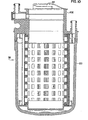
- One representative possible solution to the above problems is to provide a singular pressure vessel, sump enclosure, wherein the center filter media is replaceable while maintaining the second filter media in place.
- the mechanical filter media is contained in and encapsulated in a pressure vessel with inlet and outlet ports attached to the neck of the closure portion.
- the closure portion also features an opening to the center or core around the mechanical filter to allow a chemical filter media to be inserted therebetween. This chemical filtration media is operatively connected to the pressure vessel by seals and locking lugs.
- pressure vessel size reduction was achieved by permanently operatively positioning and encapsulating the mechanical filtration media within the pressure vessel and providing for the location of a chemical filtration media to be removably inserted within the opening within the center core of the mechanical filtration media, the chemical filtration media being attached to the pressure vessel by the previously mentioned seals and locking locks.
- Such arrangements reduce the size of the pressure vessel that would otherwise be required. It has been found that this particular arrangement works well utilizing a mechanical filter media having a life about six times the life of the chemical filtration media.
- the innovative pressure vessel has a removable center core cartridge that would allow the changing of the carbon block cartridge at the 4 month point and leave the outer membrane filtration cartridge in place within the pressure vessel. Once the useful life of the carbon block cartridge has been reached, the exhausted carbon block cartridge is removed and a new carbon block cartridge is inserted into the pressure vessel while the membrane portion operatively positioned in the pressure vessel still has useful life remaining. In one representative system, the carbon block component would be changed 6 times more often than the membrane component.
- the major benefit to the end user is that they are only changing the filtration media that is exhausted and not the filtration media that still has remaining useful filter life.
- a further object of the present disclosure is to provide an apparatus which is attractive and compact such that it occupies a minimum of countertop space and offers an outward appearance which is aesthetically pleasing to the homeowner.
- Still another object of the present disclosure is to be configured to provide an enclosed storage compartment beneath the pressure vessel for storing the tubes and connections away from the homeowner's view, and wherein such configuration provides a stable base, upon which the pressure vessel can securely rest upon a countertop or any level surface.
- Yet another object of the present disclosure to provide multistage filtration of water in a compact, appliance-like container to maximize filtration capabilities while eliminating interconnecting tubing between filtration stages and occupying a minimum amount of space.
- a fluid filtration system comprising: an upper housing; electrical components operatively positioned in the upper housing; a lower housing a pressure vessel operatively positioned in the lower housing, the pressure vessel comprising: at least two different filter media components, each being operatively positioned in the lower housing; and plumbing components for operatively connecting the pressure vessel to a fluid supply and at least one filtered fluid delivery structure.
- the present disclosure relates to a multi component counter top water filtration system having several new and unique features, including but not limited to, a counter top water filtration system 50 having two filtration media, one media being replaceable at least twice before the second media exceeds its useful life and requires replacement, presently preferably, both filtration media being housed in a single pressure vessel and, including but not limited to, a counter top water filtration system wherein the plumbing and electronic components are separated such that the lower housing component houses the plumbing components, including but not limited to, the water filtration pressure vessel, tubing and flow indication signaling device and the upper housing component houses the electronics components, including but not limited to, th e monitor 180, batteries and the flow indication receiving device and filtration methods related thereto.
- a counter top water filtration system 50 having two filtration media, one media being replaceable at least twice before the second media exceeds its useful life and requires replacement, presently preferably, both filtration media being housed in a single pressure vessel and, including but not limited to, a counter top water filtration system wherein the plumbing
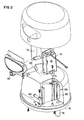
- the system 50 of the present disclosure includes four major components, those being an upper housing 52, for housing the electrical components, a lower housing 54, for housing a pressure vessel 56, the pressure vessel 56 being operatively positioned in the lower housing 54 and comprising at least two different filter media cartridges and plumbing components for connecting the pressure vessel 56 to the end users water supply.
- an upper housing 52 for housing the electrical components
- a lower housing 54 for housing a pressure vessel 56
- the pressure vessel 56 being operatively positioned in the lower housing 54 and comprising at least two different filter media cartridges and plumbing components for connecting the pressure vessel 56 to the end users water supply.
- the upper housing component 52 comprises an open area 60 for encasing the upper portion 62 of the pressure vessel 56 and for operatively cooperating with the lower housing component 54.
- the electronic components 66 of the system 50 are operatively positioned therein including the circuit board and other conventional components.
- the circuit board 70 and battery compartment 72 for housing the batteries that power the electrical system are operatively positioned internal of the upper housing 52.
- Adjacent to the battery compartment 72 is a protrusion 74 that extends from and beyond the lower surface 76 of the upper housing component 52 which is adapted for mating with a corresponding first aperture 77 operatively formed in the lower housing component 54.
- a reed switch 80 is operatively positioned in protrusion 74 of the upper housing component 52 with a magnet 82 being operatively positioned in the lower housing 54 for cooperation therewith.
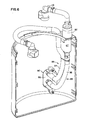
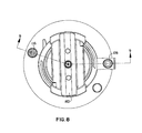
- the lower housing component 54 comprises a generally hollow container 84 presently preferably made of plastic, and including structure 86 for accommodating plumbing 88 such as, for example tubing 89, for interfacing with the pressure vessel 56 that contains the filter cartridges. As illustrated in Figure 6 , the lower housing component 54 includes a sec ond aperture 90 formed in the side thereof for routing the plumbing tubing 89 into the interior 92 of the lower housing component 54.
- Inlet 94 and outlet 96 tubing for operatively connecting the end users water supply (not shown) to the pressure vessel 56, is illustrated in Figures 1 and 7 .
- Structure 99 for operatively connecting to the end users water supply is operatively positioned at one end of both the inlet 94 and the outlet 96 tubing.
- the structure 99 includes a conventional selectable position diverter valve 98 for selectively routing water from the water supply to the pressure vessel 56 and back to the selectable positioned diverter valve 98.
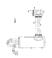
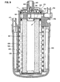
- the pressure vessel 56 of the present disclosure comprises a low er pressure element 100, presently preferably made of injected molded plastic, and an upper pressure element 102, also presently preferably, made of injected molded plastic.
- the lower and the upper injected molded pressure elements 100, 102 are operatively connected when finally assembled, presently preferably, by spin welding or other equivalent method.
- the lower pressure element 100 comprises an outer hollow area 104 for encasing a first filter media cartridge (membrane) 106 and a second hollow area 108 interior of the outer hollow area 104 for removably receiving a second filter media cartridge 110 (carbon block).
- the open end 112 of the upper pressure element 102 of the pressure vessel 56 comprises structure 114 for operatively removably positioning the second filter media cartridge 110 interior of the first filter media cartridge 106.
- the inlet 94 plumbing tubing is operatively connected to the pressure vessel 56 via an inlet port 116 operatively positioned in the upper pressure element 102 of the pressure vessel 56.
- a conventional connector 118 is operatively connected to an inlet port 116 such that the water is routed into a space 120 formed between the inner wall 122 of the lower pressure element 100 of the pressure vessel 56 and the first filter media.
- an outlet port 128 for transferring filtered water from the pressure vessel 56 back to the selectable position diverter valve 98 is operatively positioned so that the filtered water exits the pressure vessel 56 via the upper end 130 of a center core assembly 132 operatively removably positioned in the upper pressure element 102, as will be explained in more detail below, and then through the outlet 96 plumbing tubing operatively connected to the outlet port 128 in the neck 131 of the upper pressure element 102 of the pressure vessel 56.
- a pressure relief value 133 is operatively positioned on the upper surface 134 of the upper pressure element 102 of the pressure vessel 56 for allowing any air that may become trapped on the backside of the first or outer filter cartridge 106 to be bleed out of the system so that water can efficiently flow through the outer filter cartridge 106.
- a pressure relief value 133 is operatively positioned on the upper surface 134 of the upper pressure element 102 of the pressure vessel 56 for allowing any air that may become trapped on the backside of the first or outer filter cartridge 106 to be bleed out of the system so that water can efficiently flow through the outer filter cartridge 106.
- cartridges typically house a singular media type such as, for example, sediment, carbon block or membrane.
- Known prior combination filters that house several media types such as, for example, a split prefilter have typically consisted of a carbon media and a sediment filter in a singular component housing. In these type combination filters, when a combination filter cartridge was replaced, all media types were changed at the same time. Each filter cartridge was considered depleted based on the filtration media that was exhausted first. As would be understood by those skilled in the art, there was usually still some useful life remaining in one of the media that was disposed of when the cartridge was changed.
- the different filtration media utilized therein must be balanced to insure that the end user does not dispose of the filtration media having an unacceptable amount of useful filtration life remaining or excessive having filtration life that has not yet been exhausted.
- Some filtration media have a much greater potential useful life than other filtration media.
- the useful filtration life disparity between various filtration media causes a balance problem when the size of one or more of the filtration media is a limiting factor. For example, if the useful filtration life disparity between to filter media is 6x, than the choice becomes whether to increase the size of the lower useful life filtration media by 6 times, thereby resulting in a significantly larger housing or, to decrease the size of the greater useful life filtration media by 1/6th. As is known in the art, there are numerous situations where either alternative is either impossible or unacceptable.
- the present disclosure provides an acceptable solution to the filtration media balancing problem by allowing the end user to change the filtration media that has the shortest useful life at a different rate than the filtration media having the greater useful life.
- One specific representative example includes, but is not limited to, a pressure vessel 56 co mprising a carbon block filtration media cartridge 110 and a pleated membrane filtration media cartridge 106.
- the carbon block filtration media 110 cartridge could exceed its useful life in about 4 months, while the pleated membrane filtration media cartridge might not exceed its useful life for as long as 2 years, a 6x disparity. If both filtration media were in a typical single pressure vessel 56, disposing of the single pressure vessel 56 containing the two different filtration media at about the 4 month point would result in the loss of about 20 months of useful membrane life.
- the pressure vessel 56 of the present disclosure includes a removable center core assembly 132 including the carbon block filtration media cartridge 110 that would provide for the changing of the carbon block filtration media cartridge 110 mentioned above at about the 4 month point and leaves the pleated membrane filtration media cartridge in place in the pressure vessel 56.
- a new removable center core assembly 132 including the carbon block filtration media cartridge 110 would be operatively inserted into the pressure vessel 56 while the membrane filtration media cartridge still has useful life.
- the carbon block filtration media cartridge 110 component would be changed about 6 times more often than the membrane filtration media cartridge component.
- An additional feature of the preferred center core assembly 132 including the carbon block filtration media cartridge 110 is that, as presently constructed, the end user does not have to disconnect any plumbing 88 or electronic components 66 in order to change out the carbon block component filtration media cartridge 110 component, as will be discussed in more detail below.
- the representative pressure vessel 56 structure described above provides a major benefit to the end user in that the end user is only changing the filtration media cartridge that has exhausted its useful life and not the filtration media cartridge that still has useful life.
- FIG. 14-17 another representative and unique feature of the present disclosure is the structural design of the center core assembly 132 end cap 140 which includes an upper plate 142 and a lower plate 144, the lower plate 144 includes a flow path 146 for the fluid communication outside of the pressure vessel 56 without the need for a separate fluid port being position in the end cap 140.
- One especially useful benefit of this particular design is that the changing of the center core assembly 132 filtration media cartridge is accomplished without disconnecting any of the multi component counter top water filtration systems plumbing 88 fittings.
- an end user changes the center core assembly 132 filtration media cartridge at a frequency greater than the outer pressure vessel 56 filtration media cartridge, a previously unattained convenience ofbeing able to change that center core assembly 132 filter, simply and without disconnecting any plumbing connections is highly desirable and is achieved by the multi component counter top water filtration system 50 of the present disclosure.
- the center core assembly 132 filter or filtration media cartridge is replaced through the top or fluid connection end of the pressure vessel 56.
- the new and innovative end cap 140 of the present disclosure fluidly communicates outside the pressure vessel 56 via a port 128 operatively positioned on the neck 131 of the pressure vessel 56 which is then operatively connected to the outlet 96 fitting and tubing.
- the lower plate includes at least one aperture 146 operatively positioned, presently preferably, in the center thereof in order to allow the filtered water to pass through the lower plate 144 and out of the multi component counter top water filtration system 50 of the present disclosure via the outlet 128 operatively positioned in fluid communication therewith.
- the upper plate 142 of the center core assembly 132 upper end cap 140 is located parallel to and above the lower plate 144. As shown, the upper plate 142 is also sealed to the inside of the neck 131 by an O-Ring seal.
- the upper plate 142 is solid with no fluid passageways therein and thus, becomes the closure element of the pressure vessel 56.
- the two plates, upper 142 and lower 144, are held together by support ribs 148 such that a substantially rigid component results.
- the outlet port 128 and the plumbing 88 fitting related thereto is operatively positioned between the upper 142 and lower 144 plates on the neck 131 of the pressure vessel 56.
- the filtered fluid from the center core assembly 132 filtration media cartridge passes through the fluid passage means or at least one aperture 146 formed in the lower plate 144 into an area 150 formed between the upper 142 and lower 144 plates. From the area 150 between the two plates, the filtered fluid is allowed to pass though the outlet port 128 to the outlet plumbing 88 operatively positioned between the outlet port and the end user selectable valve 98 at the point of use.
- This new and innovative center core assembly 132 upper end cap 140 configuration of the present disclosure that includes the upper and lower plates as described above, facilitates the removal and replacement of the center core assembly 132 filtration media cartridge by an end user without having to disconnect the fluid outlet fitting.
- Another benefit of the new and innovative end cap 140 configuration of the present disclosure is the reliability improvement and cost reduction resulting from the reduction in the number of parts that constitute the center core assembly 132 upper end cap 140. Having an end cap 140 whose function is to insure that fluid passes through the filter media, to also be the pressure vessel 56 closure, and be the method of communicating with the outlet plumbing 88 saves both part count and labor versus assembling various possible different configurations.
- Another new, unique and innovative feature of the present disclosure comprises a handle 160 configuration that is configured such that the O-Ring seals are disengaged without rotation in order to reduce the breakout force required to remove and replace the center core assembly 132 filter media cartridge.
- one representative embodiment of the center core assembly 132 filtration media cartridge required an about 5.7cm (2.25 inch) outside diameter.
- a sized outside diameter means that the opening 112 in the top of the pressure vessel 56 need ed to be some what larger in diameter.
- the diameter of an O-Ring sealing area increases so does the force required to dislodge the O-Ring seal from their closed operating position.
- the longer the O-Ring seal remains in the closed operative position the force required to break the seal out from the closed operating position increases.
- there is a finite limit to the sealing diameter where it is no longer possible to overcome the breakout force by hand and additional force, such as, for example, a wrench is required in order to provide sufficient force to break the O-Ring seal.
- the rotational force component is effectively significantly reduced from a theoretical value of 250 to a working value of about 2.3cm (20 in* lbs) by use of the swivel joint 162.
- the handle 160 swivels to engage the filter media cartridge removal ramps 137 while the end cap 140 remains in place in the operating position, as the handle 160 continues to rotate and starts to translate due to the removal ramps 137. Since the handle 160 is attached to the end cap 140 and thus the end cap 140 follows the handle 160 in the translation. Since the ramp profile is not angular but is instead has a cam profile where the beginning of the cam is very shallow in order to apply the greatest mechanical advantage such that the breakout force is overcome.
- Another new and innovative feature of the present counter top water filtration system 50 is the effective separation of the electronic components 66 and the plumbing 88.
- the counter top water filtration system 50 of the present disclosure houses the electronic components 66 in the upper housing 52 and the plumbing 88 components in the lower housing 54. In this way, the electronic components 66 are isolated from possible condensation and other environmental factors that might cause the electronic components 66 to malfunction, such as, for example, short out.
- the flow sensing sending component 67 and the flow sensing receiving component 69 housed in protrusion 74 have been designed to be housed in separate housings components of the system 50.
- the flow switch had been a singular component.
- two components comprise a typical conventional singular component flow switch.
- One component comprises a flow sensing sending component 67 and a magnet 82 that typically resides in a flow chamber 81.
- the magnet 82 displaces in the direction of the flow. This displacement puts the magnet's magnetic field in proximity to a flow sensing receiving component 67 and reed switch 80.
- the reed switch 80 senses the magnetic field and closes to complete an electronic circuit. Because the typical magnets used in flow switches are relatively weak, the reed switch 80 needs to be located in very close proximity to the magnet 82. The need to be so proximity located is the primary reason flow switches have conventionally been sold as a singular component.
- the counter top water filtration system 50 of the present disclosure operatively positions the magnet 82 in a flow chamber 81 operatively connected to the lower housing 54 with the reed switch 80 being operatively connected to the upper housing 52.
- the first problem encountered during the development of the counter top water filtration system 50 of the present disclosure was that initially it was determined that the magnet 82 and the reed switch 80 need ed to separated by about 3 times the normal distance. This increased separation distance required a relatively stronger magnet 82 and the development of a new method for insuring that when the two components of the flow switch effectively operatively interact together, the two components are always positioned safely within the flow switch activation zone.
- the end user would separate the upper housing 52 from the lower housing 54 of the multi component counter top water filtration system 50, turn the upper housing 52 over and locate the battery compartment 72 (see Figures 2 and 20-21 ) inside the multi component counter top water filtration system 50 upper housing 52 and remove the battery compartment cover 73. Install 2 AA batteries in the battery compartment 72 insuring that the orientation of the (+) and (-) terminals for each battery is correctly installed.
- the upper housing 52 will be installed after the multi component counter top water filtration system 50 has been completely connected to the water supply structure, such as, for example, the faucet.
- connection to the water supply structure is accomplished by use of a diverter valve 98 at the end of the hoses.
- the diverter valve 98 is then connected to the faucet chosen to supply cold water to the multi component counter top water filtration system 50.
- the configuration of the end of the faucet should be matched to the appropriate adaptor (not shown) provided with the multi component counter top water filtration system 50. Install the correct adaptor and connect the diverter valve 98 securely to the end of the faucet. Then, test the diverter valve 98 connection for leaks. At this point caution should be exercised to ensure that hot water is never used in the multi component counter top water filtration system 50, as hot water will reduce the carbon filter's efficiency, among other potential adverse results thereof
- the user Before using the multi component counter top water filtration system 50 for the first time and after every carbon filter replacement, the user must flush water through the carbon filter cartridge 110 in order to remove any carbon residue and trapped air bubbles. While conducting the flush, be sure that the diverter valve 98 is set to the filtered water position.
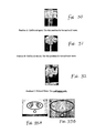
- the diverter valve 98 has three settings that control the flow of water from the water source that a user may require. A user can access each setting by turning the control handle 101 on the right side of the diverter valve 98 to any one of three positions. As best illustrated in Figures 30-32 , Position A is for unfiltered spray, which is used for hot and cold water. Position B is for unfiltered stream, which is also used for hot and cold water. Position C is for filtered cold water only. Once the diverter valve 98 is confirmed to be in the correct position, position C, turn on and flush the system for at least 5 minutes.
- the multi component counter top water filtration system 50 includes an advanced system monitor 180. To test the monitor function, a user would press and hold the button 182 under the monitor 180 for about 6 seconds. The monitor 180 should cycle through all its light functions and emit a "beep" at the end of the cycle to indicate that the system 50 is functioning properly.
- the interactive display on the face of the multi component counter top water filtration system 50 keeps a record of the remaining life in both the inner carbon filter cartridge (filter symbol 1), the outer pleated membrane filtration media cartridge (filter symbol 2) and the batteries, (2 AA).
- the display is only activated whenever water is running through the pressure vessel 56 of the system 50 or when the test button 182 (round button below the display) is pushed.
- both lights for the filter symbol 1 and the filter symbol 2 will be illuminated on both sides as shown in Figure 33B .
- Illuminated green lights indicate the amount of filtration capacity remaining in each of the respective filters.
- the display for the inner carbon filter cartridge will change over a period of approximately 4 months or after the use of about 500 liters of water.
- the five green lights around the filter symbol 1 display will go out in sequence until only the symbol for the filter symbol 1 remains and flashes red, as best illustrated in Figure 36 A .
- This red flashing display indicates that the inner carbon filter, the filter symbol 1, requires replacement.
- one green light of the outer pleated membrane filtration media cartridge display will no longer illuminate during use with the exception of the first replacement.
- the sixth carbon filter, inner carbon filter cartridge has exhausted its useful life, all the green lights around the filter symbol 2 display will no longer illuminate during use and the filter symbol 2 will flash red, as best illustrated in Figure 36 B .
- the battery life indicator appears at the bottom center of the oval faceplate of the monitor 180.
- the indicator will not light under normal use except during a monitor 180 test cycle.
- the battery indicator will emit one red flash during the test cycle.
- the indicator will blink red when the multi component counter top water filtration system 50 is dispensing water. The blinking red battery light indicates that the user has approximately 2 weeks to replace the batteries.
- the monitor 180 can be reset to the start position. Any history of water consumed and/or previous cartridge changes will be erased. To completely reset the monitor 180 to the start position, press both the test button 182 below the monitor 180 and the reset button 184 under the cover at the same time and hold for about 2 seconds until you hear a "beep". The monitor 180 circuitry will reset to 0 liters consumed and all green lights will be displayed.
- the inner carbon filter cartridge when removed from the multi component counter top water filtration system 50, will be wet. To avoid the possibility of any water dripping onto the countertop, the multi component counter top water filtration system 50 should be placed in an empty sink or next to a sink. However, care should be taken to ensure that the upper housing 52 is not accidentally dropped. Further care should be taken to ensure that the upper housing 52 is never immersed in water or any liquid.
- the inner carbon block filtration media cartridge 110 is located in the center the pressure vessel 56 and is identified by its swivel handle 160 which has a hole in the center. At this point, it should be noted that there is no need to touch the wet portion of the filter.
- the reset button 184 is located on the bottom of the upper housing 52. As best illustrated in Figure 40 A and B , to reset the interactive display, push and hold the button 184 in until a "beep" is heard (approximately 3 seconds). At this time, the interactive display will be reset to begin the countdown for the filter symbol 1, the carbon filter cartridge, to be replaced for the second time. Subsequent replacements of the filter symbol 1 will be carried out in the same manner as the initial replacement.
- flush water must be run through the replaced carbon block filtration media cartridge in order to remove any carbon residue and trapped air bubbles.
- the diverter valve 98 must be set to the filtered water position.
- the multi component counter top water filtration system 50 is turned on and the system is flushed for at least 2 minutes.
- the re-set display now shows only 4 lights remaining around the filter symbol 2. This indicates that the countdown for the replacement of the outer pleated membrane filtration media cartridge has begun.
- the sixth inner carbon filter cartridge has expired, all the lights around the filter symbol 2 will no longer illuminate during use and the filter symbol 2 will flash red.
- the outer pleated membrane filtration media cartridge will require replacement along with the inner carbon filter cartridge.
- the interactive monitor 180 will alert the user that the outer pleated membrane filtration media cartridge also requires replacement. This should occur after approximately 2 years or after the consumption of about 3,000 liters of water. At that time, the monitor 180 will display both the filter symbol 1 and the filter symbol 2 symbols in red as shown in Figure 43 .
- Outer pleated membrane filtration media cartridge replacement is somewhat similar to the inner carbon block filtration media cartridge replacement procedure.
- the end user place the multi component counter top water filtration system 50 in an empty sink or next to a sink.
- the end user will now be changing the inner carbon block filtration media cartridge at the same time the outer pleated membrane filtration media cartridge is being changed.
- the end user will remove both cartridges together as an assembly, the pressure vessel 56, from the lower housing 54.
- the carbon block filtration media cartridge is the filter that fits into the center of the pleated membrane filtration media cartridge housing portion of the pressure vessel 56.
- the lower housing 54 includes two hoses operatively attached thereto. These two hoses are disconnected by pressing the grey button on each coupling and lifting the couplings from the fittings. During this operation, care should be taken to also remove the longer tube from its push-in fitting under the base of the other coupling. At this point, make sure that both hoses are pushed aside and lift the complete pleated membrane filtration media cartridge/carbon block filtration media assembly/pressure vessel 56 out of the lower housing 54 of the multi component counter top water filtration system 50.
- the next step is to unwrap and otherwise prepare both new filters for use. Once accomplished, insert the new carbon block filtration media cartridge into the new pleated membrane filtration media cartridge filter housing portion of the pressure vessel 56, turn the carbon filter block filtration media cartridge handle 160 clockwise until one feels it stop, which completes the assembly of the new pressure vessel 56.
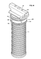
- the two vertical ribs on the pleated membrane filtration media cartridge housing must align with the cut out in the opening of the lower housing 54 in order to allow the filter assembly/pressure vessel 56 to fit completely into the lower housing 54 of the multi component counter top water filtration system 50, as best illustrated in Figures 44 A-C .
- these ribs should be lined up with the corresponding cut-out in the lower housing 54 of the multi component counter top water filtration system 50 and place the cartridge assembly/pressure vessel 56 into the lower housing 54 and position the hose back into the cut-out in the base of the fitting.
- both hoses are re-connected to their corresponding fittings by pushing the tube end couplings all the way down onto the housing fittings until they "click" in place, as best illustrated in Figures 45 A-C .
- the user Before replacing the upper housing 52, the user must reset the interactive display to ensure the correct countdown for the next two year sequence via the reset button 184 located on the bottom of the upper housing 52, as best illustrated in Figures 46 A-B . In order to accomplish this, the user pushes and holds both the test and reset button 184 simultaneously until a "beep" is heard (approximately 3 seconds). At this point, the interactive display is reset to begin the countdown for both Filter 1 and Filter 2. Replace the upper housing 52 as before.
- the user Before using the multi component counter top water filtration system 50 for the first time, the user must flush water through the replaced carbon filter cartridge and the replaced pleated membrane filtration media cartridge in order to remove any carbon residue and trapped air bubbles. While conducting the flush, be sure that the diverter valve 98 is set to the filtered water position. Once the diverter valve 98 is confirmed to be in the correct position, turn on and flush the system for at least 5 minutes as best illustrated in Figure 47.
- the diverter valve 98 is operatively connected to water source, such as, for example, a faucet (not shown).
- water source such as, for example, a faucet (not shown).
- the diverter valve is placed in the filter water position and water flows from the diverter valve to the pressure vessel via tubing 94.
- tubing 94 is routed inside of lower housing 54 and eventually to inlet 116, through outer cartridge 106 and inner cartridge 110 into hollow area 150 and out through outlet 128, as illustrated in Figure 9 .
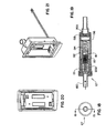
- the flow sensing sending component 67 is conventional and comprises an upper housing 190, a lower housing 192, the magnet 82, a spring 194, a spring retainer washer 196, a flow washer 198, a flow washer seat 200 and a metering piston 202.
- This flow sending sensing component operates in conjunction with the flow receiving sensing component in a conventional manner, as would be known to those skilled in the art.
- the most recently developed embodiment of the present disclosure includes the relocation of the flow washer 198, as shown in Figure 19 , to the position 199, as now indicated in Figure 9 , as it has been determined that such relocation of the flow washer 198 results in a quieter operation of the multi component counter top water filtration system of the preset disclosure.
Claims (11)
- Dispositif destiné à réduire la force d'extraction nécessaire pour enlever une cartouche de moyens de filtre installée (110) hors d'un réservoir sous pression (56), le dispositif comprenant:- un capuchon d'extrémité étanche (140) attaché à la cartouche de moyens de filtre pour loger de façon étanche la cartouche de moyens de filtre dans le réservoir sous pression;- une poignée (160) attachée au et pouvant tourner par rapport au capuchon d'extrémité étanche;- dans lequel la poignée (160) peut tourner de façon à engager une rampe d'enlèvement (137) sur le réservoir sous pression, la rampe d'enlèvement comprenant un profil de came présentant une partie peu profonde et une partie plus abrupte pour déplacer en translation la cartouche de moyens de filtre à partir du réservoir sous pression, de telle manière qu'une rotation de la poignée engage la rampe d'enlèvement pour provoquer la translation, mais pas la rotation, du capuchon d'extrémité étanche afin d'enlever la cartouche de moyens de filtre hors du réservoir sous pression, dans lequel le capuchon d'extrémité étanche (140) comprend un ou plusieurs joints toriques; et- la poignée (160) peut tourner afin d'engager initialement la partie peu profonde du profil de came pour appliquer le plus grand avantage mécanique de telle manière que la force d'extraction du capuchon d'extrémité étanche soit surpassée et que le capuchon d'extrémité étanche commence à se déplacer en translation.
- Dispositif selon la revendication 1, dans lequel la poignée (160) peut tourner davantage afin d'engager la partie plus abrupte du profil de came en vue de déplacer en translation le capuchon d'extrémité étanche (140) en dehors du réservoir sous pression.
- Dispositif selon la revendication 1 ou la revendication 2, dans lequel la poignée (160) peut tourner d'un quart de tour afin de désengager le capuchon d'extrémité étanche (140) du réservoir sous pression.
- Dispositif selon l'une quelconque des revendications 1 à 3, dans lequel le réservoir sous pression (56) comprend au moins deux composants de moyens de filtre remplaçables différents (110, 106), dans lequel la cartouche de moyens de filtre est insérée de façon amovible à l'intérieur d'une ouverture (112) à l'intérieur d'un noyau central (132) d'une deuxième cartouche de moyens de filtre (106).
- Dispositif selon la revendication 4, dans lequel la cartouche de moyens de filtre (110) comprend un moyen de filtre de réduction chimique et la deuxième cartouche de moyens de filtre (106) comprend un moyen de filtre de réduction de particules.
- Dispositif selon l'une quelconque des revendications 4 ou 5, dans lequel les moyens de filtre ayant la durée de vie la plus courte peuvent être changés à un rythme différent de celui des moyens de filtre ayant la durée de vie la plus longue.
- Procédé d'enlèvement d'une cartouche de moyens de filtre (110) hors d'un réservoir sous pression (56), comprenant les étapes suivantes:- procurer un capuchon d'extrémité étanche (140) attaché à la cartouche de moyens de filtre, le capuchon d'extrémité étanche logeant de façon étanche la cartouche de moyens de filtre dans le réservoir sous pression;- procurer une poignée (160) attachée au et pouvant tourner par rapport au capuchon d'extrémité étanche;- procurer une rampe d'enlèvement (137) sur le réservoir sous pression, la rampe d'enlèvement comprenant un profil de came présentant une partie peu profonde et une partie plus abrupte;- faire tourner la poignée afin d'engager la rampe d'enlèvement de telle manière que la rotation de la poignée provoque la translation, mais pas la rotation, du capuchon d'extrémité étanche pour enlever la cartouche de moyens de filtre hors du réservoir sous pression;- dans lequel le capuchon d'extrémité étanche (140) comprend un ou plusieurs joints toriques, et l'étape de rotation de la poignée comprend l'étape consistant à:- faire tourner la poignée (160) afin d'engager initialement la partie peu profonde du profil de came pour appliquer le plus grand avantage mécanique de telle manière que la force d'extraction du capuchon d'extrémité étanche (140) soit surpassée et que le capuchon d'extrémité étanche commence à se déplacer en translation.
- Procédé selon la revendication 7, comprenant la rotation supplémentaire de la poignée (160) afin d'engager la partie plus abrupte du profil de came en vue de déplacer en translation le capuchon d'extrémité étanche (140) en dehors du réservoir sous pression.
- Procédé selon l'une quelconque des revendications 7 ou 8, comprenant la rotation de la poignée (160) d'un quart de tour pour désengager le capuchon d'extrémité étanche (140) du réservoir sous pression.
- Procédé selon l'une quelconque des revendications 7 à 9, dans lequel l'enlèvement de la cartouche de moyens de filtre (110) hors du réservoir sous pression comprend l'enlèvement de la cartouche de moyens de filtre hors d'une ouverture (112) à l'intérieur d'un noyau central d'une deuxième cartouche de moyens de filtre (106).
- Procédé selon la revendication 10, comprenant le changement des moyens de filtre ayant la plus courte durée de vie à un rythme différent de celui des moyens de filtre ayant la plus longue durée de vie.
Applications Claiming Priority (2)
| Application Number | Priority Date | Filing Date | Title |
|---|---|---|---|
| US61431604P | 2004-09-29 | 2004-09-29 | |
| EP05800186A EP1793908B1 (fr) | 2004-09-29 | 2005-09-29 | Systeme de filtration d'eau a poser sur un comptoir |
Related Parent Applications (1)
| Application Number | Title | Priority Date | Filing Date |
|---|---|---|---|
| EP05800186.8 Division | 2005-09-29 |
Publications (2)
| Publication Number | Publication Date |
|---|---|
| EP2241361A1 EP2241361A1 (fr) | 2010-10-20 |
| EP2241361B1 true EP2241361B1 (fr) | 2011-11-09 |
Family
ID=35510981
Family Applications (2)
| Application Number | Title | Priority Date | Filing Date |
|---|---|---|---|
| EP05800186A Not-in-force EP1793908B1 (fr) | 2004-09-29 | 2005-09-29 | Systeme de filtration d'eau a poser sur un comptoir |
| EP10161996A Not-in-force EP2241361B1 (fr) | 2004-09-29 | 2005-09-29 | Système de filtration d'eau de plan de travail |
Family Applications Before (1)
| Application Number | Title | Priority Date | Filing Date |
|---|---|---|---|
| EP05800186A Not-in-force EP1793908B1 (fr) | 2004-09-29 | 2005-09-29 | Systeme de filtration d'eau a poser sur un comptoir |
Country Status (9)
| Country | Link |
|---|---|
| US (1) | US8216466B2 (fr) |
| EP (2) | EP1793908B1 (fr) |
| JP (1) | JP2008514427A (fr) |
| CN (1) | CN100540108C (fr) |
| AT (2) | ATE532568T1 (fr) |
| AU (1) | AU2005291873B2 (fr) |
| BR (1) | BRPI0516180A (fr) |
| DE (1) | DE602005021799D1 (fr) |
| WO (1) | WO2006039538A2 (fr) |
Cited By (1)
| Publication number | Priority date | Publication date | Assignee | Title |
|---|---|---|---|---|
| WO2021127215A1 (fr) * | 2019-12-17 | 2021-06-24 | Jonell filtration Products, Inc. | Système et procédé d'étanchéité d'espace confiné |
Families Citing this family (32)
| Publication number | Priority date | Publication date | Assignee | Title |
|---|---|---|---|---|
| JP2009530110A (ja) * | 2006-03-22 | 2009-08-27 | スリーエム イノベイティブ プロパティズ カンパニー | 流体濾過システム |
| KR20080083903A (ko) * | 2007-03-13 | 2008-09-19 | 삼성전자주식회사 | 정수장치 |
| GB0715247D0 (en) * | 2007-08-04 | 2007-09-12 | Parker Hannifin Ltd | Filter assembly |
| GB0715269D0 (en) | 2007-08-04 | 2007-09-12 | Parker Hannifin Ltd | Filter assembly |
| US7749383B2 (en) * | 2007-09-06 | 2010-07-06 | Cummins Filtration Ip, Inc. | Filter cartridge with crush ribs |
| US7935255B2 (en) * | 2007-09-06 | 2011-05-03 | Cummins Filtration Ip, Inc. | Filter cartridge |
| CN102245277B (zh) | 2008-11-04 | 2014-07-23 | 3M创新有限公司 | 流体互连器 |
| US10918985B2 (en) | 2008-11-04 | 2021-02-16 | 3M Innovative Properties Company | Filter element and seal therefor |
| KR102030301B1 (ko) * | 2009-01-12 | 2019-10-08 | 액세스 비지니스 그룹 인터내셔날 엘엘씨 | 사용 시점 수처리 시스템 |
| US8308942B2 (en) * | 2010-05-14 | 2012-11-13 | Paragon Water Systems, Inc. | Filter system with removable enhancement media |
| US8261919B2 (en) * | 2010-08-25 | 2012-09-11 | Dow Global Technologies Llc | Fluid filter module including handle |
| ES2713041T3 (es) * | 2011-02-25 | 2019-05-17 | Panasonic Corp | Dispositivo inalámbrico para lectura automatizada de contadores |
| CN103702944B (zh) * | 2011-06-10 | 2017-11-03 | 三菱化学株式会社 | 净水滤筒以及壶型净水器 |
| CA2880601C (fr) * | 2013-01-21 | 2019-06-04 | Aquasana, Inc. | Systemes, elements, et procedes de filtration de liquide |
| CA2942497A1 (fr) * | 2013-03-15 | 2014-09-18 | Zero Technologies, Llc | Bouteille a filtration d'eau a alimentation par gravite et double echange ionique |
| US9815725B2 (en) * | 2014-08-08 | 2017-11-14 | Multipure International | Self-contained water filtration system and method of using the same |
| US9783430B2 (en) | 2014-08-12 | 2017-10-10 | Multipure International | Self-contained water filtration system including wireless communication and filter verification and method of using the same |
| US10434453B2 (en) | 2014-12-31 | 2019-10-08 | Ingersoll-Rand Company | Compressor system having filter assembly with replaceable filter element holder |
| WO2016191233A2 (fr) | 2015-05-22 | 2016-12-01 | Access Business Group International Llc | Système de traitement de l'eau au point d'utilisation |
| CN105107256B (zh) * | 2015-08-04 | 2016-11-16 | 达格玛(厦门)环保科技有限公司 | 方便装拆净水机 |
| EP3334509B1 (fr) * | 2015-08-14 | 2020-03-18 | 3M Innovative Properties Company | Capteur électromagnétique pour la surveillance active de support filtrant dans un système de filtration |
| WO2017036362A1 (fr) * | 2015-09-02 | 2017-03-09 | 佛山市美的清湖净水设备有限公司 | Purificateur d'eau et procédé de détection de durée de vie d'élément filtrant |
| CN105107254B (zh) * | 2015-09-02 | 2018-01-02 | 佛山市美的清湖净水设备有限公司 | 净水机和检测滤芯的寿命的方法 |
| CN105582734B (zh) * | 2016-02-18 | 2019-03-08 | 佛山市顺德区美的饮水机制造有限公司 | 滤芯和具有滤芯的净水系统 |
| US10240327B2 (en) | 2016-07-18 | 2019-03-26 | Haier Us Appliance Solutions, Inc. | Passive-fluid dosing assembly |
| USD868693S1 (en) * | 2017-08-23 | 2019-12-03 | Synaptive Medical (Barbados) Inc. | Snap connector |
| CN110523125B (zh) * | 2019-09-27 | 2021-08-24 | 广东科创智水科技有限公司 | 一种智能化的污水处理过滤器及其工作方法 |
| USD969964S1 (en) | 2020-03-06 | 2022-11-15 | Pentair Residential Filtration, Llc | Filtration system |
| US11897788B2 (en) | 2021-10-05 | 2024-02-13 | Paragon Water Systems, Inc. | Filter system with enhanced display |
| USD991395S1 (en) * | 2021-10-06 | 2023-07-04 | Paragon Water Systems, Inc. | Filter system housing with display |
| CN113856291B (zh) * | 2021-10-21 | 2023-05-16 | 枣阳惠祥有机硅有限公司 | 一种加工过滤处理系统 |
| CN117160105B (zh) * | 2023-11-03 | 2024-01-02 | 瀚玛斯(山西)医药科技有限公司 | 一种滴眼剂生产过滤装置 |
Family Cites Families (21)
| Publication number | Priority date | Publication date | Assignee | Title |
|---|---|---|---|---|
| US3533509A (en) * | 1968-11-21 | 1970-10-13 | Marvel Eng Co | Universal filter housing head construction |
| US4487691A (en) * | 1984-01-09 | 1984-12-11 | Thermo Electron Corporation | Deep fat fryer with swivel filter element |
| US4555337A (en) * | 1984-10-23 | 1985-11-26 | The Wooster Brush Company | Plug and filter assembly for paint sprayer |
| US5151180A (en) * | 1989-10-17 | 1992-09-29 | Cuno, Incorporated | Radial and axial flow stage filter device |
| US5078876A (en) | 1990-01-17 | 1992-01-07 | Trysan Research, Inc. | Apparatus for multistage purification of water |
| US5128034A (en) * | 1991-03-21 | 1992-07-07 | Amway Corporation | Pressure vessel for housing a water filter |
| US5275213A (en) * | 1993-01-22 | 1994-01-04 | Perko, Inc. | Fuel filling and venting device |
| US5529201A (en) * | 1994-05-20 | 1996-06-25 | Stant Manufacturing Inc. | Cam-on filler neck cap |
| DE19502020C2 (de) * | 1995-01-24 | 2002-02-28 | Mann & Hummel Filter | Flüssigkeitsfilter |
| US5876610A (en) | 1997-03-19 | 1999-03-02 | Clack Corporation | Method and apparatus for monitoring liquid flow through an enclosed stream |
| US5888381A (en) | 1997-05-16 | 1999-03-30 | United States Filter Corporation | Water filter with pressure actuated flow monitor |
| US6149801A (en) * | 1997-08-08 | 2000-11-21 | Water Pik, Inc,. | Water treatment device with volumetric monitoring features |
| CA2346792A1 (fr) | 1998-10-08 | 2000-04-13 | Cuno Incorporated | Unite de filtrage |
| US6120685A (en) * | 1999-02-26 | 2000-09-19 | Maytag Corporation | Water filtering system with replaceable cartridge for a refrigerator |
| US6602412B2 (en) * | 2001-03-01 | 2003-08-05 | Inflos Designs | Single cartridge filter housing |
| US6627078B1 (en) * | 2001-08-22 | 2003-09-30 | Nelson Industries, Inc. | Filter element cover grip |
| US7615152B2 (en) | 2001-08-23 | 2009-11-10 | Pur Water Purification Products, Inc. | Water filter device |
| US6780316B2 (en) * | 2001-10-13 | 2004-08-24 | Professional Dental Manufacturing | Water filtering apparatus with element support |
| JP3827997B2 (ja) * | 2001-11-20 | 2006-09-27 | 大阪ガスケミカル株式会社 | 浄化器 |
| AU2003231002B2 (en) * | 2002-04-19 | 2008-07-24 | 3M Innovative Properties Company | Encapsulated filter cartridge |
| JP2006517864A (ja) * | 2003-01-28 | 2006-08-03 | ドナルドソン カンパニー,インコーポレイティド | 濾過組立体及び濾過方法 |
-
2005
- 2005-09-29 AT AT10161996T patent/ATE532568T1/de active
- 2005-09-29 EP EP05800186A patent/EP1793908B1/fr not_active Not-in-force
- 2005-09-29 AU AU2005291873A patent/AU2005291873B2/en not_active Ceased
- 2005-09-29 BR BRPI0516180-0A patent/BRPI0516180A/pt not_active Application Discontinuation
- 2005-09-29 AT AT05800186T patent/ATE470493T1/de not_active IP Right Cessation
- 2005-09-29 EP EP10161996A patent/EP2241361B1/fr not_active Not-in-force
- 2005-09-29 WO PCT/US2005/035267 patent/WO2006039538A2/fr active Application Filing
- 2005-09-29 CN CNB2005800329855A patent/CN100540108C/zh not_active Expired - Fee Related
- 2005-09-29 JP JP2007534814A patent/JP2008514427A/ja active Pending
- 2005-09-29 DE DE602005021799T patent/DE602005021799D1/de active Active
- 2005-09-29 US US11/239,607 patent/US8216466B2/en not_active Expired - Fee Related
Cited By (1)
| Publication number | Priority date | Publication date | Assignee | Title |
|---|---|---|---|---|
| WO2021127215A1 (fr) * | 2019-12-17 | 2021-06-24 | Jonell filtration Products, Inc. | Système et procédé d'étanchéité d'espace confiné |
Also Published As
| Publication number | Publication date |
|---|---|
| EP2241361A1 (fr) | 2010-10-20 |
| DE602005021799D1 (de) | 2010-07-22 |
| CN101031345A (zh) | 2007-09-05 |
| US20060065607A1 (en) | 2006-03-30 |
| WO2006039538A3 (fr) | 2006-10-12 |
| WO2006039538A2 (fr) | 2006-04-13 |
| AU2005291873B2 (en) | 2010-07-29 |
| BRPI0516180A (pt) | 2008-08-26 |
| AU2005291873A1 (en) | 2006-04-13 |
| ATE532568T1 (de) | 2011-11-15 |
| CN100540108C (zh) | 2009-09-16 |
| EP1793908A2 (fr) | 2007-06-13 |
| ATE470493T1 (de) | 2010-06-15 |
| JP2008514427A (ja) | 2008-05-08 |
| US8216466B2 (en) | 2012-07-10 |
| EP1793908B1 (fr) | 2010-06-09 |
Similar Documents
| Publication | Publication Date | Title |
|---|---|---|
| EP2241361B1 (fr) | Système de filtration d'eau de plan de travail | |
| US7743788B2 (en) | Faucet assembly with water quality indicator | |
| US6241103B1 (en) | Filter cartridge for water treatment device | |
| RU2429200C2 (ru) | Устройство для питьевой воды | |
| CA2666742C (fr) | Appareil pour boitier de filtre avec mecanisme rotatif de remplacement de filtre | |
| EP1121187B1 (fr) | Unite de filtrage | |
| KR100804302B1 (ko) | 정수기용 필터카트리지 결합구조 | |
| EP0947231A1 (fr) | Dispositif de traitement d'eau | |
| US20060037893A1 (en) | Single-use long-life faucet-mounted water filtration devices | |
| KR19990045055A (ko) | 다단식 물 필터 시스템 | |
| KR20180072879A (ko) | 사용 시점 수처리 시스템 | |
| JP2008514427A5 (fr) | ||
| US20070221561A1 (en) | Liquid filtration systems | |
| CN216863814U (zh) | 一种带可分拆水箱的净饮水机 | |
| CN114105236A (zh) | 一种模块式净饮水器 | |
| JPH11253936A (ja) | 浄水器 | |
| CN112441632B (zh) | 净水机 | |
| CN212089241U (zh) | 净水豆浆一体机 | |
| CN208684593U (zh) | 净水机 | |
| CN217015609U (zh) | 滤芯及净水设备 | |
| US11897788B2 (en) | Filter system with enhanced display | |
| JP2606777Y2 (ja) | 浄水器 | |
| JP2569491Y2 (ja) | 浄水器 | |
| JP2604026Y2 (ja) | 浄水器 | |
| KR970006098Y1 (ko) | 정수기 |
Legal Events
| Date | Code | Title | Description |
|---|---|---|---|
| PUAI | Public reference made under article 153(3) epc to a published international application that has entered the european phase |
Free format text: ORIGINAL CODE: 0009012 |
|
| AC | Divisional application: reference to earlier application |
Ref document number: 1793908 Country of ref document: EP Kind code of ref document: P |
|
| AK | Designated contracting states |
Kind code of ref document: A1 Designated state(s): AT BE BG CH CY CZ DE DK EE ES FI FR GB GR HU IE IS IT LI LT LU LV MC NL PL PT RO SE SI SK TR |
|
| GRAP | Despatch of communication of intention to grant a patent |
Free format text: ORIGINAL CODE: EPIDOSNIGR1 |
|
| 17P | Request for examination filed |
Effective date: 20110420 |
|
| GRAS | Grant fee paid |
Free format text: ORIGINAL CODE: EPIDOSNIGR3 |
|
| GRAA | (expected) grant |
Free format text: ORIGINAL CODE: 0009210 |
|
| AC | Divisional application: reference to earlier application |
Ref document number: 1793908 Country of ref document: EP Kind code of ref document: P |
|
| AK | Designated contracting states |
Kind code of ref document: B1 Designated state(s): AT BE BG CH CY CZ DE DK EE ES FI FR GB GR HU IE IS IT LI LT LU LV MC NL PL PT RO SE SI SK TR |
|
| REG | Reference to a national code |
Ref country code: GB Ref legal event code: FG4D |
|
| REG | Reference to a national code |
Ref country code: CH Ref legal event code: EP |
|
| REG | Reference to a national code |
Ref country code: IE Ref legal event code: FG4D |
|
| REG | Reference to a national code |
Ref country code: DE Ref legal event code: R096 Ref document number: 602005031179 Country of ref document: DE Effective date: 20120119 |
|
| REG | Reference to a national code |
Ref country code: NL Ref legal event code: VDEP Effective date: 20111109 |
|
| LTIE | Lt: invalidation of european patent or patent extension |
Effective date: 20111109 |
|
| PG25 | Lapsed in a contracting state [announced via postgrant information from national office to epo] |
Ref country code: IS Free format text: LAPSE BECAUSE OF FAILURE TO SUBMIT A TRANSLATION OF THE DESCRIPTION OR TO PAY THE FEE WITHIN THE PRESCRIBED TIME-LIMIT Effective date: 20120309 Ref country code: LT Free format text: LAPSE BECAUSE OF FAILURE TO SUBMIT A TRANSLATION OF THE DESCRIPTION OR TO PAY THE FEE WITHIN THE PRESCRIBED TIME-LIMIT Effective date: 20111109 |
|
| PG25 | Lapsed in a contracting state [announced via postgrant information from national office to epo] |
Ref country code: PT Free format text: LAPSE BECAUSE OF FAILURE TO SUBMIT A TRANSLATION OF THE DESCRIPTION OR TO PAY THE FEE WITHIN THE PRESCRIBED TIME-LIMIT Effective date: 20120309 Ref country code: SE Free format text: LAPSE BECAUSE OF FAILURE TO SUBMIT A TRANSLATION OF THE DESCRIPTION OR TO PAY THE FEE WITHIN THE PRESCRIBED TIME-LIMIT Effective date: 20111109 Ref country code: SI Free format text: LAPSE BECAUSE OF FAILURE TO SUBMIT A TRANSLATION OF THE DESCRIPTION OR TO PAY THE FEE WITHIN THE PRESCRIBED TIME-LIMIT Effective date: 20111109 Ref country code: PL Free format text: LAPSE BECAUSE OF FAILURE TO SUBMIT A TRANSLATION OF THE DESCRIPTION OR TO PAY THE FEE WITHIN THE PRESCRIBED TIME-LIMIT Effective date: 20111109 Ref country code: BE Free format text: LAPSE BECAUSE OF FAILURE TO SUBMIT A TRANSLATION OF THE DESCRIPTION OR TO PAY THE FEE WITHIN THE PRESCRIBED TIME-LIMIT Effective date: 20111109 Ref country code: NL Free format text: LAPSE BECAUSE OF FAILURE TO SUBMIT A TRANSLATION OF THE DESCRIPTION OR TO PAY THE FEE WITHIN THE PRESCRIBED TIME-LIMIT Effective date: 20111109 Ref country code: GR Free format text: LAPSE BECAUSE OF FAILURE TO SUBMIT A TRANSLATION OF THE DESCRIPTION OR TO PAY THE FEE WITHIN THE PRESCRIBED TIME-LIMIT Effective date: 20120210 Ref country code: LV Free format text: LAPSE BECAUSE OF FAILURE TO SUBMIT A TRANSLATION OF THE DESCRIPTION OR TO PAY THE FEE WITHIN THE PRESCRIBED TIME-LIMIT Effective date: 20111109 |
|
| PG25 | Lapsed in a contracting state [announced via postgrant information from national office to epo] |
Ref country code: CY Free format text: LAPSE BECAUSE OF FAILURE TO SUBMIT A TRANSLATION OF THE DESCRIPTION OR TO PAY THE FEE WITHIN THE PRESCRIBED TIME-LIMIT Effective date: 20111109 |
|
| PG25 | Lapsed in a contracting state [announced via postgrant information from national office to epo] |
Ref country code: EE Free format text: LAPSE BECAUSE OF FAILURE TO SUBMIT A TRANSLATION OF THE DESCRIPTION OR TO PAY THE FEE WITHIN THE PRESCRIBED TIME-LIMIT Effective date: 20111109 Ref country code: BG Free format text: LAPSE BECAUSE OF FAILURE TO SUBMIT A TRANSLATION OF THE DESCRIPTION OR TO PAY THE FEE WITHIN THE PRESCRIBED TIME-LIMIT Effective date: 20120209 Ref country code: CZ Free format text: LAPSE BECAUSE OF FAILURE TO SUBMIT A TRANSLATION OF THE DESCRIPTION OR TO PAY THE FEE WITHIN THE PRESCRIBED TIME-LIMIT Effective date: 20111109 Ref country code: DK Free format text: LAPSE BECAUSE OF FAILURE TO SUBMIT A TRANSLATION OF THE DESCRIPTION OR TO PAY THE FEE WITHIN THE PRESCRIBED TIME-LIMIT Effective date: 20111109 Ref country code: SK Free format text: LAPSE BECAUSE OF FAILURE TO SUBMIT A TRANSLATION OF THE DESCRIPTION OR TO PAY THE FEE WITHIN THE PRESCRIBED TIME-LIMIT Effective date: 20111109 |
|
| PG25 | Lapsed in a contracting state [announced via postgrant information from national office to epo] |
Ref country code: IT Free format text: LAPSE BECAUSE OF FAILURE TO SUBMIT A TRANSLATION OF THE DESCRIPTION OR TO PAY THE FEE WITHIN THE PRESCRIBED TIME-LIMIT Effective date: 20111109 Ref country code: RO Free format text: LAPSE BECAUSE OF FAILURE TO SUBMIT A TRANSLATION OF THE DESCRIPTION OR TO PAY THE FEE WITHIN THE PRESCRIBED TIME-LIMIT Effective date: 20111109 |
|
| PLBE | No opposition filed within time limit |
Free format text: ORIGINAL CODE: 0009261 |
|
| STAA | Information on the status of an ep patent application or granted ep patent |
Free format text: STATUS: NO OPPOSITION FILED WITHIN TIME LIMIT |
|
| REG | Reference to a national code |
Ref country code: AT Ref legal event code: MK05 Ref document number: 532568 Country of ref document: AT Kind code of ref document: T Effective date: 20111109 |
|
| 26N | No opposition filed |
Effective date: 20120810 |
|
| REG | Reference to a national code |
Ref country code: DE Ref legal event code: R097 Ref document number: 602005031179 Country of ref document: DE Effective date: 20120810 |
|
| PG25 | Lapsed in a contracting state [announced via postgrant information from national office to epo] |
Ref country code: AT Free format text: LAPSE BECAUSE OF FAILURE TO SUBMIT A TRANSLATION OF THE DESCRIPTION OR TO PAY THE FEE WITHIN THE PRESCRIBED TIME-LIMIT Effective date: 20111109 |
|
| PG25 | Lapsed in a contracting state [announced via postgrant information from national office to epo] |
Ref country code: MC Free format text: LAPSE BECAUSE OF NON-PAYMENT OF DUE FEES Effective date: 20120930 Ref country code: ES Free format text: LAPSE BECAUSE OF FAILURE TO SUBMIT A TRANSLATION OF THE DESCRIPTION OR TO PAY THE FEE WITHIN THE PRESCRIBED TIME-LIMIT Effective date: 20120220 |
|
| REG | Reference to a national code |
Ref country code: CH Ref legal event code: PL |
|
| GBPC | Gb: european patent ceased through non-payment of renewal fee |
Effective date: 20120929 |
|
| REG | Reference to a national code |
Ref country code: IE Ref legal event code: MM4A |
|
| PG25 | Lapsed in a contracting state [announced via postgrant information from national office to epo] |
Ref country code: FI Free format text: LAPSE BECAUSE OF FAILURE TO SUBMIT A TRANSLATION OF THE DESCRIPTION OR TO PAY THE FEE WITHIN THE PRESCRIBED TIME-LIMIT Effective date: 20111109 |
|
| REG | Reference to a national code |
Ref country code: FR Ref legal event code: ST Effective date: 20130531 |
|
| PG25 | Lapsed in a contracting state [announced via postgrant information from national office to epo] |
Ref country code: CH Free format text: LAPSE BECAUSE OF NON-PAYMENT OF DUE FEES Effective date: 20120930 Ref country code: IE Free format text: LAPSE BECAUSE OF NON-PAYMENT OF DUE FEES Effective date: 20120929 Ref country code: GB Free format text: LAPSE BECAUSE OF NON-PAYMENT OF DUE FEES Effective date: 20120929 Ref country code: LI Free format text: LAPSE BECAUSE OF NON-PAYMENT OF DUE FEES Effective date: 20120930 |
|
| PG25 | Lapsed in a contracting state [announced via postgrant information from national office to epo] |
Ref country code: FR Free format text: LAPSE BECAUSE OF NON-PAYMENT OF DUE FEES Effective date: 20121001 |
|
| PG25 | Lapsed in a contracting state [announced via postgrant information from national office to epo] |
Ref country code: TR Free format text: LAPSE BECAUSE OF FAILURE TO SUBMIT A TRANSLATION OF THE DESCRIPTION OR TO PAY THE FEE WITHIN THE PRESCRIBED TIME-LIMIT Effective date: 20111109 |
|
| PG25 | Lapsed in a contracting state [announced via postgrant information from national office to epo] |
Ref country code: LU Free format text: LAPSE BECAUSE OF NON-PAYMENT OF DUE FEES Effective date: 20120929 |
|
| PG25 | Lapsed in a contracting state [announced via postgrant information from national office to epo] |
Ref country code: HU Free format text: LAPSE BECAUSE OF FAILURE TO SUBMIT A TRANSLATION OF THE DESCRIPTION OR TO PAY THE FEE WITHIN THE PRESCRIBED TIME-LIMIT Effective date: 20050929 |
|
| PGFP | Annual fee paid to national office [announced via postgrant information from national office to epo] |
Ref country code: DE Payment date: 20150922 Year of fee payment: 11 |
|
| REG | Reference to a national code |
Ref country code: DE Ref legal event code: R119 Ref document number: 602005031179 Country of ref document: DE |
|
| PG25 | Lapsed in a contracting state [announced via postgrant information from national office to epo] |
Ref country code: DE Free format text: LAPSE BECAUSE OF NON-PAYMENT OF DUE FEES Effective date: 20170401 |