EP2241294A2 - Elastischer Verbinder für bewegliche Verbindung mit sechs Grad Spiel - Google Patents
Elastischer Verbinder für bewegliche Verbindung mit sechs Grad Spiel Download PDFInfo
- Publication number
- EP2241294A2 EP2241294A2 EP10007571A EP10007571A EP2241294A2 EP 2241294 A2 EP2241294 A2 EP 2241294A2 EP 10007571 A EP10007571 A EP 10007571A EP 10007571 A EP10007571 A EP 10007571A EP 2241294 A2 EP2241294 A2 EP 2241294A2
- Authority
- EP
- European Patent Office
- Prior art keywords
- degrees
- arms
- spacer
- freedom
- resilient connector
- Prior art date
- Legal status (The legal status is an assumption and is not a legal conclusion. Google has not performed a legal analysis and makes no representation as to the accuracy of the status listed.)
- Withdrawn
Links
- 125000006850 spacer group Chemical group 0.000 claims abstract description 17
- 238000000465 moulding Methods 0.000 claims description 2
- 229920003023 plastic Polymers 0.000 claims 1
- 239000004033 plastic Substances 0.000 claims 1
- 210000003127 knee Anatomy 0.000 description 11
- 239000000463 material Substances 0.000 description 10
- 210000002683 foot Anatomy 0.000 description 8
- 241001465754 Metazoa Species 0.000 description 6
- 210000003423 ankle Anatomy 0.000 description 6
- 239000000835 fiber Substances 0.000 description 6
- 238000004519 manufacturing process Methods 0.000 description 6
- 229920000728 polyester Polymers 0.000 description 5
- 229920000271 Kevlar® Polymers 0.000 description 4
- 239000004761 kevlar Substances 0.000 description 4
- 230000002787 reinforcement Effects 0.000 description 4
- 230000035939 shock Effects 0.000 description 4
- OKTJSMMVPCPJKN-UHFFFAOYSA-N Carbon Chemical compound [C] OKTJSMMVPCPJKN-UHFFFAOYSA-N 0.000 description 3
- 239000004744 fabric Substances 0.000 description 3
- 239000011521 glass Substances 0.000 description 3
- 229910002804 graphite Inorganic materials 0.000 description 3
- 239000010439 graphite Substances 0.000 description 3
- 239000004698 Polyethylene Substances 0.000 description 2
- 229920001971 elastomer Polymers 0.000 description 2
- 239000000806 elastomer Substances 0.000 description 2
- 238000001746 injection moulding Methods 0.000 description 2
- 210000000629 knee joint Anatomy 0.000 description 2
- 210000002414 leg Anatomy 0.000 description 2
- 229920001778 nylon Polymers 0.000 description 2
- 229920000573 polyethylene Polymers 0.000 description 2
- -1 polyethylenes Polymers 0.000 description 2
- 229920001296 polysiloxane Polymers 0.000 description 2
- 229920002635 polyurethane Polymers 0.000 description 2
- 239000004814 polyurethane Substances 0.000 description 2
- 229920000785 ultra high molecular weight polyethylene Polymers 0.000 description 2
- 244000025254 Cannabis sativa Species 0.000 description 1
- 235000012766 Cannabis sativa ssp. sativa var. sativa Nutrition 0.000 description 1
- 235000012765 Cannabis sativa ssp. sativa var. spontanea Nutrition 0.000 description 1
- 229920000106 Liquid crystal polymer Polymers 0.000 description 1
- 239000004977 Liquid-crystal polymers (LCPs) Substances 0.000 description 1
- 239000004433 Thermoplastic polyurethane Substances 0.000 description 1
- 239000004699 Ultra-high molecular weight polyethylene Substances 0.000 description 1
- 229920000508 Vectran Polymers 0.000 description 1
- 239000004979 Vectran Substances 0.000 description 1
- 229920003235 aromatic polyamide Polymers 0.000 description 1
- 235000009120 camo Nutrition 0.000 description 1
- 235000005607 chanvre indien Nutrition 0.000 description 1
- 238000010276 construction Methods 0.000 description 1
- 239000011152 fibreglass Substances 0.000 description 1
- 239000011487 hemp Substances 0.000 description 1
- 239000000203 mixture Substances 0.000 description 1
- 238000012986 modification Methods 0.000 description 1
- 230000004048 modification Effects 0.000 description 1
- 229920000642 polymer Polymers 0.000 description 1
- 229920002959 polymer blend Polymers 0.000 description 1
- 238000001228 spectrum Methods 0.000 description 1
- 229910001220 stainless steel Inorganic materials 0.000 description 1
- 239000010935 stainless steel Substances 0.000 description 1
- 229920002994 synthetic fiber Polymers 0.000 description 1
- 229920006352 transparent thermoplastic Polymers 0.000 description 1
- 238000004804 winding Methods 0.000 description 1
Images


Classifications
-
- A—HUMAN NECESSITIES
- A61—MEDICAL OR VETERINARY SCIENCE; HYGIENE
- A61F—FILTERS IMPLANTABLE INTO BLOOD VESSELS; PROSTHESES; DEVICES PROVIDING PATENCY TO, OR PREVENTING COLLAPSING OF, TUBULAR STRUCTURES OF THE BODY, e.g. STENTS; ORTHOPAEDIC, NURSING OR CONTRACEPTIVE DEVICES; FOMENTATION; TREATMENT OR PROTECTION OF EYES OR EARS; BANDAGES, DRESSINGS OR ABSORBENT PADS; FIRST-AID KITS
- A61F5/00—Orthopaedic methods or devices for non-surgical treatment of bones or joints; Nursing devices ; Anti-rape devices
- A61F5/01—Orthopaedic devices, e.g. long-term immobilising or pressure directing devices for treating broken or deformed bones such as splints, casts or braces
- A61F5/0102—Orthopaedic devices, e.g. long-term immobilising or pressure directing devices for treating broken or deformed bones such as splints, casts or braces specially adapted for correcting deformities of the limbs or for supporting them; Ortheses, e.g. with articulations
- A61F5/0123—Orthopaedic devices, e.g. long-term immobilising or pressure directing devices for treating broken or deformed bones such as splints, casts or braces specially adapted for correcting deformities of the limbs or for supporting them; Ortheses, e.g. with articulations for the knees
-
- A—HUMAN NECESSITIES
- A61—MEDICAL OR VETERINARY SCIENCE; HYGIENE
- A61F—FILTERS IMPLANTABLE INTO BLOOD VESSELS; PROSTHESES; DEVICES PROVIDING PATENCY TO, OR PREVENTING COLLAPSING OF, TUBULAR STRUCTURES OF THE BODY, e.g. STENTS; ORTHOPAEDIC, NURSING OR CONTRACEPTIVE DEVICES; FOMENTATION; TREATMENT OR PROTECTION OF EYES OR EARS; BANDAGES, DRESSINGS OR ABSORBENT PADS; FIRST-AID KITS
- A61F5/00—Orthopaedic methods or devices for non-surgical treatment of bones or joints; Nursing devices ; Anti-rape devices
- A61F5/01—Orthopaedic devices, e.g. long-term immobilising or pressure directing devices for treating broken or deformed bones such as splints, casts or braces
- A61F5/0102—Orthopaedic devices, e.g. long-term immobilising or pressure directing devices for treating broken or deformed bones such as splints, casts or braces specially adapted for correcting deformities of the limbs or for supporting them; Ortheses, e.g. with articulations
- A61F5/0127—Orthopaedic devices, e.g. long-term immobilising or pressure directing devices for treating broken or deformed bones such as splints, casts or braces specially adapted for correcting deformities of the limbs or for supporting them; Ortheses, e.g. with articulations for the feet
-
- A—HUMAN NECESSITIES
- A61—MEDICAL OR VETERINARY SCIENCE; HYGIENE
- A61F—FILTERS IMPLANTABLE INTO BLOOD VESSELS; PROSTHESES; DEVICES PROVIDING PATENCY TO, OR PREVENTING COLLAPSING OF, TUBULAR STRUCTURES OF THE BODY, e.g. STENTS; ORTHOPAEDIC, NURSING OR CONTRACEPTIVE DEVICES; FOMENTATION; TREATMENT OR PROTECTION OF EYES OR EARS; BANDAGES, DRESSINGS OR ABSORBENT PADS; FIRST-AID KITS
- A61F5/00—Orthopaedic methods or devices for non-surgical treatment of bones or joints; Nursing devices ; Anti-rape devices
- A61F5/01—Orthopaedic devices, e.g. long-term immobilising or pressure directing devices for treating broken or deformed bones such as splints, casts or braces
- A61F5/0102—Orthopaedic devices, e.g. long-term immobilising or pressure directing devices for treating broken or deformed bones such as splints, casts or braces specially adapted for correcting deformities of the limbs or for supporting them; Ortheses, e.g. with articulations
- A61F2005/0132—Additional features of the articulation
- A61F2005/0146—Additional features of the articulation combining rotational and sliding movements, e.g. simulating movements of a natural joint
- A61F2005/0148—Floating pivotal axis
Definitions
- the present invention relates to a movable joint having up to six degrees of freedom.
- Complex movable joints such as the human knee joint, allow relative movement of two parts in six degrees of freedom.
- Six degrees of freedom refers to movement relative to three orthogonally opposed axes, plus rotation about each of those three axes.
- Previously proposed movable joints having more than one degree of freedom typically connect two parts by pins that are pivotable and angularly movable in fixed slots.
- Such pin-in-slot movable joints cannot simulate the natural anatomical movement of human or animal joints in up to six degrees of freedom.
- the rigidity of pin-in-slot movable joints means they are unable to absorb shocks, vibrations and loads applied to them.
- Such a movable joint has many potential uses, for example, use in human or animal joint support devices.
- a movable joint including:
- the present invention also provides a movable joint system including:
- the present invention further provides a joint support device for a human or animal joint including two support portions which are connected for relative movement about the human or animal joint by at least one movable joint of the present invention and/or by the movable joint system of the present invention.
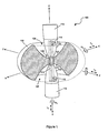
- FIG. 1 illustrates a generic embodiment of a movable joint 100 of the present invention.
- the movable joint 100 includes a body 102 having two spaced apertures 104, 106 connected by an opening 108, as depicted in the cross-section of the body 102.
- the size, shape and spacing of the apertures 104, 106 will vary for any particular application.
- Two arms 110, 112 have ends receivable in, and at least partially abutting, the apertures 104, 106.
- the size and shape of the abutting ends of the arms 110, 112 will also vary for any particular application.
- the body 102 and/or the arms 110, 112 can be manufactured by, for example, injection moulding.
- the body 102 and/or the arms 110, 112 can be manufactured from, for example, polymeric materials, such as polyurethanes, silicones, polyethylenes, nylons, polyesters, and polyester elastomers, and combinations thereof.
- the polymeric materials can include reinforcements such as glass cloth or fibres, graphite fibres, Kevlar (trade mark) fibres and Spheretex (trade mark) fibres. Other suitable manufacturing methods and materials will be apparent to those skilled in the art.
- a resilient connector 114 illustrated in phantom in Figure 1 passes through the opening 108 and connects the ends of the arms 110, 112 in the apertures 104, 106.
- the resilient connector 114 is releasably connected to the ends of the arms 110, 112 by releasable fasteners 116, 118, for example, screws.
- the resilience of the resilient connector 114 allows independent movement of the arms 110, 112 in up to six degrees of freedom which is controlled by engagement of abutment portions 120 of the arms 110, 112 with respective abutment portions 122 of the apertures 104, 106.
- three orthogonal axes X, Y, Z provide a reference direction for each of the six degrees of freedom of movement.
- the six degrees of freedom of the arms 110, 112 include three translation degrees T X , T Y , T Z and three rotational degrees R X , R Y , R Z .
- Figures 2-4 illustrate various example positions of the arms 110, 112 in movement with six degrees of freedom.
- the resilience of the resilient connector 114 absorbs forces applied to the arms 110, 112 such as shocks, vibrations and loads.
- external tensile, compressive and/or torsional forces and loads applied to the arms 110, 112 may be dampened, absorbed or resisted.
- Figures 5-7 illustrate sequential steps in the manufacture of one embodiment of the resilient connector 114.
- Manufacture of this embodiment starts with an integral assembly of two spaced spools 124, 126 connected by a spacer 128.
- the integral assembly of the spools 124, 126 and the spacer 128 is then placed in jig (not shown), and a pretensioned spine 130 is formed by winding fibre around and between the spools 124, 126 both longitudinally and radially relative to the spacer 128, as depicted in Figure 6 .
- a resilient member 132 is then moulded over the spools 124, 126 and the pretensioned spine 130.
- the spools 124, 126 have transverse through-holes for receiving fasteners to connect the resilient connector 114 to the arms 110, 112.
- the pretensioned spine 130 resists tensile loads applied to the arms 110, 112.
- the spacer 128 can provide a degree of stiffness in the manufactured resilient connector 114.
- Figure 8 illustrates an alternative embodiment of the resilient connector 114.
- the pretensioned spine 130 is formed by tying fibre between inner portions of the two end-plugs 134, 136.
- the resilient member 132 is then moulded over inner portions of the end-plugs 134, 136 and the pretensioned spine 130.
- the outer portions of the end-plugs 134, 136 have transverse through-holes for receiving fasteners to connect the resilient connector 114 to the arms 110, 112.
- the spools 124, 126 and/or the spacer 128 can be made by, for example, injection moulding.
- the spools 124, 126 and/or the spacer 128 can be made from, for example, polymeric materials, such as polyurethanes, silicones, polyethylenes, nylons, polyesters, and polyester elastomers, and combinations thereof.
- the polymeric materials can include reinforcements such as glass cloth or fibres, graphite fibres, Kevlar (trade mark) fibres and Spheretex (trade mark) fibres.
- the end-plugs 134, 136 can be made from, for example, stainless steel.
- the pretensioned spine 130 can be made from, for example, natural or synthetic fibres having high tensile strength, flex fatigue resistance, and low creep. Suitable materials include: polyester or liquid crystal polymer fibres, such as Vectran (trade mark) fibre; aramid fibres, such as Kevlar (trade mark) fibre; ultra-high molecular weight polyethylene fibres, such as Dyneema (trade mark) fibre or Spectra (trade mark) fibre; and natural fibres, such as hemp.
- the resilient member 132 can be made from, for example, transparent thermoplastic polyurethane so that the integrity of the pretensioned spine 130 can be visually inspected. Other suitable manufacturing methods and materials will be apparent to those skilled in the art.
- the generic movable joint 100 can be customised for any particular application by controlling the geometry of the apertures 104, 106 and/or the abutting ends of the arms 110, 112, and/or by controlling the resilience characteristics of the resilient connector 114.
- independent movement of the arms 110, 112 in up to six degrees of freedom may be controlled by selection of the respective three-dimensional shape of the abutment portions 120, 122 of the arms 110, 112 and/or the apertures 104, 106, and/or by selection of the resilience characteristics of the resilient connector 114.
- the independent movement of the arms in six degrees of freedom may be controlled to substantially simulate anatomical movement of a human or animal joint in up to six degrees of freedom.
- FIG 9 illustrates a knee brace 200 having upper and lower leg support frames 202, 204 connected by two movable joints 206a, 206b.
- the upper and lower leg support frames 202, 204 can be adapted to be secured to the upper and lower leg by, for example, straps and hook and loop fasteners (not shown).
- Each movable joint 206a, 206b includes two arms 208, 210 respectively connected at one end to the upper and lower leg support frames 202, 204 via screws 212.
- the other end of each arm 208, 210 is received in a body 214.
- the arms 208, 210 are connected in apertures 216, 218 of the body 214 by a resilient connector 220 which is depicted in phantom.
- the resilient connector 220 is releasably connected to the ends of the arms 208, 210 by screws 222 which allow the arms 208, 210 to be readily disconnected from and connected to the body 214.
- the upper and lower leg support frames 202, 204 can be manufactured by, for example, moulding.
- the upper and lower leg support frames 202, 204 can be manufactured from, for example, fibreglass, with or without reinforcements. Reinforcements, if used, can include glass cloth or fibres, graphite fibres, Kevlar (trade mark) fibres and Spheretex (trade mark) fibres. Other suitable manufacturing methods and materials will be apparent to those skilled in the art.
- the body 214 and/or the arms 208, 210 can be manufactured from the same materials as the body 102 and/or the arms 110, 112, as discussed hereinbefore.
- the resilient connector 220 can be manufactured from the same materials as the resilient connector 114, as discussed hereinbefore.
- Each movable joint 206a, 206b is customised to simulate natural anatomical movement of a human knee joint in up to six degrees of freedom.
- the six degrees of freedom of the human knee include three rotational degrees - flexion/extension, abduction/adduction, internal/external - and three translation degrees - anterior/posterior, medial/lateral, proximal/distal.
- the movable joints 206a, 206b have the same general functionality as the generic movable joint 100, as discussed hereinbefore.
- the independent movement of the arms 208, 210 in up to six degrees of freedom can be customised by controlling the geometry of the apertures 216, 218 and/or the abutting ends of the arms 208, 210, and/or by controlling the resilience characteristics of the resilient connector 220.
- Figures 11-14 depict embodiments of the body 214 with apertures 216, 218 having different example geometries for controlling the range of movement of the knee brace 200 in up to six degrees of freedom.
- Figure 11 is a cross-section of an embodiment of the body 214 in which the apertures 216, 218 are shaped to control the range of flexion and extension of the knee brace 200 from approximately 0 degrees extension to approximately 15 degrees of flexion.
- Figure 12 depicts an alternative cross-section of the body 214 in which the apertures 216, 218 are shaped to control the range of flexion and extension of the knee brace 200 from approximately 5 degrees extension to approximately 30 degrees of flexion.
- the apertures 216, 218 have been shaped to control the range of flexion and extension from approximately 10 degrees extension to approximately 45 degrees of flexion.
- Figure 14 is a top view of an embodiment of the body 214 in which the apertures 216, 218 have been shaped to control internal/external rotation during flexion and extension from approximately 0 degrees to approximately 15 degrees.
- the different embodiments of the body 214 depicted in Figure 11-14 can comprise a movable joint system in which the apertures 216, 218 of each body 214 are differently shaped to the apertures 216, 218 of other bodies 214.
- the arms 208, 210 are capable of being readily disconnected from and connected to the different bodies 214 via the screws 222 to limit independent movement of the arms 208, 210 at different selected angles of flexion and extension.
- the different bodies 214 may therefore be interchanged so that any given movable joint 206a, 206b is tailored to the needs of a wearer of the knee brace 200.
- the different bodies 214 may be changed as the needs of the patient change.
- the bodies 214 may be changed accordingly.
- the limits of independent movement of the arms 208, 210 in up to six degrees of freedom may be easily modified by simply interchanging the bodies 214 to meet the needs of the second patient.
- FIG 15 illustrates an ankle brace 300 having a lower leg support frame 302 and a foot support frame 304 connected by two movable joints 306a, 306b.
- the lower leg and foot support frames 302, 304 can be adapted to be secured to the lower leg and the foot by, for example, straps and hook and loop fasteners (not shown).
- the components of the ankle brace 300 and the movable joints 306a, 306b have the same general construction and composition as the knee brace 200 and the movable joints 206a, 206a, as discussed hereinbefore.
- Each movable joint 306a, 306b therefore generally includes a body 308 having two apertures 310, 312 receiving two arms 314, 316 connected by a resilient connector 318.
- the shape of the abutment portions of the apertures 310, 312 and the abutting ends of the arms 314, 316 of the movable joints 306a, 306b is customised to control the movement of the lower leg support frame 302 and the foot support frame 304 in several degrees of freedom corresponding to the natural anatomical movement of the human ankle.
- the degrees of freedom of the ankle include dorsiflexion, plantar flexion, inversion and eversion.
- Dorsiflexion is movement in which the foot is pivoted toward the leg.
- Plantar flexion is movement in which the foot is pivoted away from the leg.
- Inversion is movement when the foot turns inwards
- eversion is movement when the foot rotates outwards.
- the geometry of the apertures 310, 312 allows dorsiflexion and plantar flexion of the ankle brace 300 while controlling inversion, eversion and twisting.
- embodiments of the present invention provide a simple, low cost movable joint having up to six degrees of freedom which is capable of absorbing shocks, vibrations and loads.
- a movable joint has many potential uses including, but not limited to, use in human or animal joint support devices.
- Embodiments of the movable joint of the present invention can have essentially any shape and can be made completely from polymers or polymer blends.
Landscapes
- Health & Medical Sciences (AREA)
- Nursing (AREA)
- Orthopedic Medicine & Surgery (AREA)
- Engineering & Computer Science (AREA)
- Biomedical Technology (AREA)
- Heart & Thoracic Surgery (AREA)
- Vascular Medicine (AREA)
- Life Sciences & Earth Sciences (AREA)
- Animal Behavior & Ethology (AREA)
- General Health & Medical Sciences (AREA)
- Public Health (AREA)
- Veterinary Medicine (AREA)
- Orthopedics, Nursing, And Contraception (AREA)
- Prostheses (AREA)
- Rehabilitation Tools (AREA)
- Actuator (AREA)
- Pivots And Pivotal Connections (AREA)
- Manipulator (AREA)
Applications Claiming Priority (2)
| Application Number | Priority Date | Filing Date | Title |
|---|---|---|---|
| AU2004906657A AU2004906657A0 (en) | 2004-11-19 | Improvements in hinges and hinged brace means | |
| EP05804535A EP1811930B1 (de) | 2004-11-19 | 2005-11-18 | Bewegliches gelenk mit bis zu sechs freiheitsgraden |
Related Parent Applications (1)
| Application Number | Title | Priority Date | Filing Date |
|---|---|---|---|
| EP05804535.2 Division | 2005-11-18 |
Publications (2)
| Publication Number | Publication Date |
|---|---|
| EP2241294A2 true EP2241294A2 (de) | 2010-10-20 |
| EP2241294A3 EP2241294A3 (de) | 2010-12-01 |
Family
ID=36406776
Family Applications (2)
| Application Number | Title | Priority Date | Filing Date |
|---|---|---|---|
| EP10007571A Withdrawn EP2241294A3 (de) | 2004-11-19 | 2005-11-18 | Elastischer Verbinder für bewegliche Verbindung mit sechs Grad Spiel |
| EP05804535A Expired - Lifetime EP1811930B1 (de) | 2004-11-19 | 2005-11-18 | Bewegliches gelenk mit bis zu sechs freiheitsgraden |
Family Applications After (1)
| Application Number | Title | Priority Date | Filing Date |
|---|---|---|---|
| EP05804535A Expired - Lifetime EP1811930B1 (de) | 2004-11-19 | 2005-11-18 | Bewegliches gelenk mit bis zu sechs freiheitsgraden |
Country Status (10)
| Country | Link |
|---|---|
| US (1) | US8157755B2 (de) |
| EP (2) | EP2241294A3 (de) |
| JP (1) | JP5054536B2 (de) |
| CN (1) | CN100443066C (de) |
| AT (1) | ATE516779T1 (de) |
| AU (1) | AU2005306586B2 (de) |
| CA (1) | CA2587410C (de) |
| ES (1) | ES2368494T3 (de) |
| NZ (1) | NZ555029A (de) |
| WO (1) | WO2006053391A1 (de) |
Families Citing this family (18)
| Publication number | Priority date | Publication date | Assignee | Title |
|---|---|---|---|---|
| WO2008061300A1 (en) * | 2006-11-20 | 2008-05-29 | Pod I.P. Pty Ltd | Knee brace with self-tracking patella guard |
| EP2276431A2 (de) * | 2008-05-14 | 2011-01-26 | Össur HF | Beinstütze |
| JP5384665B2 (ja) * | 2009-02-03 | 2014-01-08 | ポッド・アイ・ピー・プロプライエタリー・リミテッド | 調節交換式の膝装具 |
| AU335294S (en) | 2011-02-08 | 2011-03-02 | Pod Ip Pty Ltd | Knee brace |
| US9345605B2 (en) | 2012-05-31 | 2016-05-24 | Ossur Hf | Hinge for an orthopedic device |
| US9115776B2 (en) | 2012-11-19 | 2015-08-25 | City University Of Hong Kong | Flexing arrangement |
| JP6241180B2 (ja) * | 2013-10-01 | 2017-12-06 | セイコーエプソン株式会社 | 指アシスト装置 |
| WO2015123259A1 (en) | 2014-02-11 | 2015-08-20 | Ossur Hf | Hinge for an orthopedic device |
| US9668903B2 (en) | 2014-11-20 | 2017-06-06 | Ossur Iceland Ehf | Polymeric polycentric hinge |
| WO2017080137A1 (zh) * | 2015-11-13 | 2017-05-18 | 上海逸动医学科技有限公司 | 关节运动检测系统、方法及膝关节动态评估方法、系统 |
| CN106279437B (zh) | 2016-08-19 | 2017-10-31 | 安源医药科技(上海)有限公司 | 高糖基化人凝血因子viii融合蛋白及其制备方法与用途 |
| US11096803B2 (en) | 2016-12-06 | 2021-08-24 | Ossur Iceland Ehf | Movable joint for use in a prosthetic or orthopedic system |
| US10531973B2 (en) * | 2017-01-09 | 2020-01-14 | Roshanak BAGHAEI ROODSARI | Apparatus for treating and supporting extremities or a portion of a body |
| WO2018236225A1 (en) * | 2017-06-20 | 2018-12-27 | Opum Technologies Limited | ORTHESIS OR EXOSQUELET SYSTEM WITH MODULAR ELEMENTS |
| CA3159653C (en) | 2017-12-07 | 2025-07-08 | 2330-2029 Quebec Inc. | Helical axis knee orthosis and its design and manufacturing process |
| DE102018132959A1 (de) * | 2018-12-19 | 2020-06-25 | Ottobock Se & Co. Kgaa | Gelenk für eine orthopädietechnische Einrichtung |
| EP3946174B1 (de) | 2019-03-26 | 2023-08-16 | Ossur Iceland Ehf | Scharnieranordnung für eine orthopädische vorrichtung |
| DE102019116417A1 (de) * | 2019-06-17 | 2020-12-17 | Michael Wagner | Orthese mit einer ein bikondyläres Gelenk nachbildenden Gelenkeinrichtung und Gelenkeinrichtung |
Family Cites Families (14)
| Publication number | Priority date | Publication date | Assignee | Title |
|---|---|---|---|---|
| IE52501B1 (en) | 1981-01-30 | 1987-11-25 | Oec Europ Ltd | A joint prosthesis |
| FR2610513B1 (fr) * | 1987-02-09 | 1992-06-05 | Merle Michel | Prothese articulaire |
| US5086760A (en) | 1989-04-14 | 1992-02-11 | Neumann Holm W | Articulated orthotic brace for an anatomical joint |
| IT1277790B1 (it) | 1995-02-17 | 1997-11-12 | Tecres Spa | Protesi metacarpo-falangea ed interfalangea per articolazioni della mano o del piede |
| US5534033A (en) | 1995-06-05 | 1996-07-09 | Carbomedics, Inc. | Orthopedic prosthetic implants with pyrolytic carbon or ceramic articulating surfaces |
| JP3500551B2 (ja) * | 1995-10-12 | 2004-02-23 | 澄子 山本 | 短下肢装具 |
| CN2302770Y (zh) * | 1996-01-09 | 1999-01-06 | 渤海化工(集团)股份有限公司天津化工厂 | 髋关节固定支架 |
| NZ286038A (en) * | 1996-02-21 | 1998-10-28 | Bodyworks Healthcare Ltd | Knee brace includes at least one arm offset along a length thereof |
| US6689080B2 (en) * | 2000-05-24 | 2004-02-10 | Asterisk.Asterisk Llc | Joint brace with limb-conforming arcuately adjustable cuffs |
| US20030083602A1 (en) * | 2001-11-01 | 2003-05-01 | Haaland Peter D. | Flexible joint protection device |
| US20040002376A1 (en) | 2002-06-27 | 2004-01-01 | Swift Brian D. | Gaming device having an incrementing award bonus scheme |
| EP1539058A4 (de) * | 2002-06-28 | 2014-06-25 | Generation Ii Usa Inc | Anatomisch geformte orthopädische knieschiene |
| CN2565426Y (zh) * | 2002-09-05 | 2003-08-13 | 上海大学 | 一种人工关节 |
| US7192407B2 (en) * | 2003-01-30 | 2007-03-20 | Djo, Llc | Motion controlling hinge for orthopedic brace |
-
2005
- 2005-11-18 ES ES05804535T patent/ES2368494T3/es not_active Expired - Lifetime
- 2005-11-18 AU AU2005306586A patent/AU2005306586B2/en not_active Expired
- 2005-11-18 WO PCT/AU2005/001755 patent/WO2006053391A1/en not_active Ceased
- 2005-11-18 AT AT05804535T patent/ATE516779T1/de not_active IP Right Cessation
- 2005-11-18 JP JP2007541582A patent/JP5054536B2/ja not_active Expired - Fee Related
- 2005-11-18 EP EP10007571A patent/EP2241294A3/de not_active Withdrawn
- 2005-11-18 NZ NZ555029A patent/NZ555029A/en not_active IP Right Cessation
- 2005-11-18 CN CNB2005800397994A patent/CN100443066C/zh not_active Expired - Lifetime
- 2005-11-18 CA CA2587410A patent/CA2587410C/en not_active Expired - Fee Related
- 2005-11-18 EP EP05804535A patent/EP1811930B1/de not_active Expired - Lifetime
- 2005-11-18 US US11/791,057 patent/US8157755B2/en active Active
Non-Patent Citations (1)
| Title |
|---|
| None |
Also Published As
| Publication number | Publication date |
|---|---|
| EP1811930A4 (de) | 2009-04-01 |
| ES2368494T3 (es) | 2011-11-17 |
| CA2587410C (en) | 2015-01-27 |
| US8157755B2 (en) | 2012-04-17 |
| CN100443066C (zh) | 2008-12-17 |
| EP1811930B1 (de) | 2011-07-20 |
| AU2005306586A1 (en) | 2006-05-26 |
| JP5054536B2 (ja) | 2012-10-24 |
| AU2005306586B2 (en) | 2011-11-24 |
| US20090030356A1 (en) | 2009-01-29 |
| CN101060819A (zh) | 2007-10-24 |
| NZ555029A (en) | 2009-09-25 |
| WO2006053391A1 (en) | 2006-05-26 |
| CA2587410A1 (en) | 2006-05-26 |
| ATE516779T1 (de) | 2011-08-15 |
| EP1811930A1 (de) | 2007-08-01 |
| JP2008520289A (ja) | 2008-06-19 |
| EP2241294A3 (de) | 2010-12-01 |
Similar Documents
| Publication | Publication Date | Title |
|---|---|---|
| EP1811930B1 (de) | Bewegliches gelenk mit bis zu sechs freiheitsgraden | |
| US7749182B2 (en) | Stay hinge for orthopedic supports and method of using same | |
| US4489718A (en) | Knee brace hinge | |
| AU2005325135B2 (en) | Frame for an orthopedic brace including offset hinges | |
| US9572702B2 (en) | Shoulder orthosis including flexion/extension device | |
| US5817041A (en) | Rigid lower-limb orthotic | |
| US20070106189A1 (en) | Multi-functional joint brace | |
| US20090305827A1 (en) | Sports throwing training device | |
| US20110111890A1 (en) | Sports throwing training device | |
| KR20220121768A (ko) | 떨림 안정화 장치 | |
| KR20220003524A (ko) | 웨어러블 보조 장치 | |
| US7862527B2 (en) | Edge binding for orthopedic supports and method of using same | |
| US7749423B2 (en) | Method of producing an orthotic brace or prosthetic device | |
| MX2010013894A (es) | Accesorio de articulacion. | |
| US12059366B2 (en) | Joint orthosis with resiliently deformable hinge | |
| US20160074199A1 (en) | Reinforced lower limb orthotic brace | |
| US20240016643A1 (en) | External ankle brace | |
| ES2956207T3 (es) | Dispositivo y procedimiento de asistencia para la movilización de una articulación | |
| WO2018163477A1 (ja) | 膝肘関節アシスト装置 | |
| US12533252B1 (en) | Elbow brace with twist adjustment | |
| KR20100005505A (ko) | 복합재료 무릎 보조기 | |
| JP2024032583A (ja) | 装具 | |
| WO2014099739A2 (en) | Limb protection device |
Legal Events
| Date | Code | Title | Description |
|---|---|---|---|
| PUAI | Public reference made under article 153(3) epc to a published international application that has entered the european phase |
Free format text: ORIGINAL CODE: 0009012 |
|
| 17P | Request for examination filed |
Effective date: 20100721 |
|
| AC | Divisional application: reference to earlier application |
Ref document number: 1811930 Country of ref document: EP Kind code of ref document: P |
|
| AK | Designated contracting states |
Kind code of ref document: A2 Designated state(s): AT BE BG CH CY CZ DE DK EE ES FI FR GB GR HU IE IS IT LI LT LU LV MC NL PL PT RO SE SI SK TR |
|
| PUAL | Search report despatched |
Free format text: ORIGINAL CODE: 0009013 |
|
| AK | Designated contracting states |
Kind code of ref document: A3 Designated state(s): AT BE BG CH CY CZ DE DK EE ES FI FR GB GR HU IE IS IT LI LT LU LV MC NL PL PT RO SE SI SK TR |
|
| 17Q | First examination report despatched |
Effective date: 20110614 |
|
| STAA | Information on the status of an ep patent application or granted ep patent |
Free format text: STATUS: THE APPLICATION IS DEEMED TO BE WITHDRAWN |
|
| 18D | Application deemed to be withdrawn |
Effective date: 20111025 |