EP2241171B1 - Werkzeughalterungsvorrichtung zur Aufrechterhaltung der Werkzeuge in Arbeitsposition für adaptierbare Formen - Google Patents
Werkzeughalterungsvorrichtung zur Aufrechterhaltung der Werkzeuge in Arbeitsposition für adaptierbare Formen Download PDFInfo
- Publication number
- EP2241171B1 EP2241171B1 EP10159293A EP10159293A EP2241171B1 EP 2241171 B1 EP2241171 B1 EP 2241171B1 EP 10159293 A EP10159293 A EP 10159293A EP 10159293 A EP10159293 A EP 10159293A EP 2241171 B1 EP2241171 B1 EP 2241171B1
- Authority
- EP
- European Patent Office
- Prior art keywords
- shackle
- triangular
- section
- mounting holes
- knives
- Prior art date
- Legal status (The legal status is an assumption and is not a legal conclusion. Google has not performed a legal analysis and makes no representation as to the accuracy of the status listed.)
- Active
Links
- 230000001737 promoting effect Effects 0.000 claims description 4
- 238000006073 displacement reaction Methods 0.000 abstract description 2
- 210000004027 cell Anatomy 0.000 description 5
- 239000004575 stone Substances 0.000 description 4
- 238000012423 maintenance Methods 0.000 description 3
- 206010035148 Plague Diseases 0.000 description 2
- 241000607479 Yersinia pestis Species 0.000 description 2
- 230000000712 assembly Effects 0.000 description 2
- 238000000429 assembly Methods 0.000 description 2
- 230000000694 effects Effects 0.000 description 2
- 230000003042 antagnostic effect Effects 0.000 description 1
- 238000005265 energy consumption Methods 0.000 description 1
- 238000000034 method Methods 0.000 description 1
- 238000013138 pruning Methods 0.000 description 1
- 238000009966 trimming Methods 0.000 description 1
Images


Classifications
-
- A—HUMAN NECESSITIES
- A01—AGRICULTURE; FORESTRY; ANIMAL HUSBANDRY; HUNTING; TRAPPING; FISHING
- A01D—HARVESTING; MOWING
- A01D34/00—Mowers; Mowing apparatus of harvesters
- A01D34/01—Mowers; Mowing apparatus of harvesters characterised by features relating to the type of cutting apparatus
- A01D34/412—Mowers; Mowing apparatus of harvesters characterised by features relating to the type of cutting apparatus having rotating cutters
- A01D34/42—Mowers; Mowing apparatus of harvesters characterised by features relating to the type of cutting apparatus having rotating cutters having cutters rotating about a horizontal axis, e.g. cutting-cylinders
- A01D34/52—Cutting apparatus
- A01D34/535—Cutting apparatus with cutting members pivotally attached to the rotating axle, e.g. flails
Definitions
- the present invention generally relates to a tool holder device for a cutting or grinding machine.
- Such devices consist of a shaft carrying tools working in the manner of plagues during the rotation of the shaft and equip for example machines for cutting and / or grinding plants such as rotary mowers used for the cutting crops, the bulldozers used for the maintenance of green spaces, roadsides ... or grinding machines used in different techniques such as grinding stones.
- the tool holder shaft is positioned horizontally, while in the mowers used for hedge trimming the tree is positioned vertically.
- Said tree can also be arranged obliquely for certain cuts made in height on plants such as pruning.
- the cutting and / or grinding work is performed under the best conditions when the tool is arranged radially relative to the shaft, under the action of the centrifugal force; so that the effort he applies to the products to be treated is as important as possible.
- the tool-carrying device comprises a shaft, often constituted by a hollow tube, equipped with clevises positioned perpendicularly to its axis and bearing axial supports, that is to say parallel to the axis of the shaft, supporting the tools through their mounting hole.
- At least one tool is mounted on each axial support, the machines preferably having two tools on each axial support.
- the yokes are usually positioned in pairs, each pair carrying an axial support, which carries one or two tools or a shackle, which carries the one or both tools.
- the shackle can rotate around its axial support; as well as the tool or tools can turn around the shackle.
- EP 2039234 A1 describes a device according to the preamble of claims 1, 3 and 5.
- the tools are returned to their working position, generally perpendicular to the shaft that the door, by the centrifugal force generated by the rotation of the shaft.
- the object of the present invention is to provide a tool holder device which provides a cutting efficiency as important as that obtained with machines running at a very high speed and this with a reduced rotational speed in order to save energy.
- the present invention relates to a tool-holder device of the type constituted by a shaft, provided with clevises carrying an axial support, which pivotally carries an intermediate element or shackle, the lower part or rod passes through the mounting holes of the cutting flails or grinding machine, characterized in that the mounting holes, either of the shackle, or flails, or both have shapes matching those of the axial support and / or those of the shaft of the shackle with a clearance important, which allows their relative displacement, when the beam hits an obstacle, while promoting its return in axial position due to the centrifugal force, even when it is weak because of the relatively slow rotation of the tree which carry the tools.
- obstacle is used herein to refer to any object that interferes with the operation of the tool and disrupts its work.
- a bailer a stone, a stump, a too thick branch or too dense vegetation can constitute an obstacle against which will abut the tool.
- the device according to the invention is intended to equip a bailer and is designated by “flail” the cutting tool or grinding of the vegetation comprising a working part and a mounting means having an orifice, which is traversed by a support means said "axial support”.
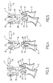
- the tool-holder device consists of a shaft 1, generally in the form of a hollow shaft, provided with clevises 10, which bear an axial support 11 or 12; the axial support 11 being of circular section, while the axial support 12 is of triangular section.
- the axial support 11 is of circular section and passes through the two circular orifices 30 of a shackle 3.
- the diameter of the orifices 30 is slightly larger than that of the support 10, so that the shackle 3 can pivot freely around said support.
- the lower portion 311 of the shackle 3, hereinafter called “rod” is of triangular section.
- This triangular rod 311 passes through the mounting holes 21 of the tools or flails 2, which comprise a tapered working part.
- the mounting holes 21 have a triangular shape corresponding to that of the shaft 311 of the shackle 3, that is to say that the triangles have equal angles; but different dimensions, the sides of the triangles 21 being larger than the sides of the rod 311.
- the sides of the triangles 21 have a length almost double that of the sides of the rod 311.
- the axial support 12 is of triangular section and passes through the two mounting holes 31 of the shackle 3, which are also triangular. As in the previous example, as regards the shapes and dimensions of the triangles, they have equal angles, but sides of different lengths, the sides of the triangles 31 being larger than those of the axial support 12.
- the sides of the triangles 31 have a length almost double that of the sides of the axial support 12.
- the rod 34 of the shackle 3 passes through the mounting holes 20 of the flails 2.
- This rod is of circular section and said mounting holes 20 have an oblong shape whose width is slightly larger than the diameter of the rod 34; so that it can rotate freely.
- the axial support 12 is of triangular section; that it passes through the two mounting holes 31 of the shackle 3; that the Rod 311 of the shackle 3 is also of triangular section and the mounting holes 21 of the flails also.
- the device of the figure 5 therefore constitutes an addition of the means of Figures 3 and 4 .
- the shapes and dimensions of the triangles have the same characteristics.
- the Figures 6, 7 and 8 illustrate the operation of the device of the figure 3 .
- the position represented in figure 6 is the normal working position for which the beam 2 is disposed radially relative to the shaft 1 and is kept spaced from said shaft under the effect of the centrifugal force generated by the rotation of said shaft.
- the plague has the possibility of retreating when it encounters an obstacle; because the dimensions of the triangle of the orifice 21 are greater than those of the triangle of the axial support.
- the device of the figure 3 allows a double retraction; since the beam 2 has pivoted around the shaft of the shackle 3 and the latter has rotated by around its axial support.
Landscapes
- Life Sciences & Earth Sciences (AREA)
- Environmental Sciences (AREA)
- Gripping On Spindles (AREA)
- Moulds For Moulding Plastics Or The Like (AREA)
- Harvester Elements (AREA)
- Automatic Tool Replacement In Machine Tools (AREA)
- Manipulator (AREA)
- Hooks, Suction Cups, And Attachment By Adhesive Means (AREA)
Claims (6)
- Werkzeughalterungsvorrichtung für eine Welle (1), mit einen Axialträger (11, 12) tragenden Gabeln (10), die zum Drehen ein Zwischenelement oder einen Schäkel (3) tragen, dessen unteres Teil oder Schaft durch die Montageöffnungen der Schneid- oder Zerkleinerungsflegel (2) geht, wobei der Axialträger (11) einen kreisförmigen Querschnitt aufweist und durch die zwei kreisförmigen Öffnungen (30) des Schäkels (3) geht,
dadurch gekennzeichnet, daß der Schaft des Schäkels einen dreieckigen Querschnitt aufweist, die Montageöffnungen (21) der Flegel (2), die in deren nicht arbeitenden Teil liegen, eine entsprechende Dreiecksform mit Abmessungen aufweisen, die derart größer sind als die des dreieckigen Querschnitts des Schafts (311) des Schäkels (3), daß die Montageöffnungen (21) der Schlegel (2) solche Dreiecksformen aufweisen, die an den Dreiecksquerschnitt des Schaftes (311) des Schäkels (3) mit einem relevanten Spiel angepaßt sind, das ihre relative Bewegung ermöglicht, wenn der Schlegel ein Hindernis trifft, um eine Rückkehr der Schlegel in die Axialposition aufgrund der Zentrifugalkraft zu begünstigen, auch wenn sie gering ist aufgrund der relativ langsamen Drehung der Welle (1), die die Schlegel (2) mit einer Geschwindigkeit von weniger als 3000 Umdrehungen pro Minute trägt. - Werkzeughalterungsvorrichtung nach Anspruch 1, dadurch gekennzeichnet, daß die Abmessungen der Montageöffnung (21) jedes Flegels (2) so gut wie das Doppelte der des Schaftes (311) des Schäkels (3) betragen.
- Werkzeughalterungsvorrichtung für eine Welle (1), mit einen Axialträger (11, 12) tragenden Gabeln (10), die zum Drehen ein Zwischenelement oder einen Schäkel (3) tragen, dessen unteres Teil oder Schaft durch die Montageöffnungen der Schneid- oder Zerkleinerungsflegel (2) geht, wobei der Schaft (34) des Schäkels einen kreisförmigen Querschnitt aufweist, die Öffnungen (20) der Schlegel (2), die in deren nicht arbeitenden Teil liegen, eine länglich Form mit einer Breite aufweisen, die etwas größer ist als der Durchmesser des Schaftes (34) des Schäkels (3),
dadurch gekennzeichnet, daß der Axialträger (12) einen dreieckigen Querschnitt aufweist und durch zwei dreieckige Montageöffnungen (31) des Schäkels (3) geht, die derart größere Abmessungen aufweisen, daß die Montageöffnungen (31) des Schäkels (3) solche Dreiecksformen aufweisen, die an den Dreiecksquerschnitt des Axialträgers (12) mit einem relevanten Spiel angepaßt sind, das ihre relative Bewegung ermöglicht, wenn der Schlegel ein Hindernis trifft, um eine Rückkehr der Schäkels in die Axialposition aufgrund der Zentrifugalkraft zu begünstigen, auch wenn sie gering ist aufgrund der relativ langsamen Drehung der Welle (1), die die Schlegel (2) mit einer Geschwindigkeit von weniger als 3000 Umdrehungen pro Minute trägt. - Werkzeughalterungsvorrichtung nach Anspruch 3, dadurch gekennzeichnet, daß die Abmessungen der dreieckigen Montageöffnungen (31) des Schäkels (3) auf dem dreieckigen Axialträger so gut wie das Doppelte der des Axialträgers (12) betragen.
- Werkzeughalterungsvorrichtung für eine Welle (1), mit einen Axialträger (11, 12) tragenden Gabeln (10), die zum Drehen ein Zwischenelement oder einen Schäkel (3) tragen, dessen unteres Teil oder Schaft durch die Montageöffnungen der Schneid- oder Zerkleinerungsflegel (2) geht,
dadurch gekennzeichnet, daß der Axialträger (11) einen dreieckigen Querschnitt aufweist und durch zwei dreieckige Öffnungen (31) des Schäkels (3) geht, die derart größere Abmessungen aufweisen, daß die Montageöffnungen (31) des Schäkels (3) dreieckige Formen aufweisen, die an den Dreiecksquerschnitt des Axialträgers (12) mit einem relevanten Spiel angepaßt sind, und daß der Schaft (311) des Schäkels auch einen dreieckigen Querschnitt aufweist und durch die Montageöffnungen (21) der Schlegel (2) geht, die ebenfalls dreieckig sind und größere Abmessungen derart aufweisen, daß die Montageöffnungen (21) der Schlegel (2) dreieckige Formen aufweisen, die an den Dreiecksquerschnitt des Schaftes (311) des Schäkels (3) mit einem relevanten Spiel angepaßt sind, das die relative Bewegung zwischen dem Schlegel und der Gabel und zwischen den Schlegeln und dem Schäkel ermöglicht, wenn der Schlegel ein Hindernis trifft, um ihre Rückkehr in die Axialposition aufgrund der Zentrifugalkraft zu begünstigen, auch wenn sie gering ist aufgrund der relativ langsamen Drehung der Welle (1), die die Schlegel (2) mit einer Geschwindigkeit von weniger als 3000 Umdrehungen pro Minute trägt. - Werkzeughalterungsvorrichtung nach Anspruch 5, dadurch gekennzeichnet, daß die Abmessungen der dreieckigen Montageöffnungen (31) des Schäkels (3) auf dem Axialträger mit dreieckigen Querschnitt so gut wie das Doppelte der des Axialträgers betragen und daß ferner die Abmessungen der Montageöffnung (21) der Flegel (2) auf dem dreieckigen Schaft (311) des Schäkels (3) so gut wie das Doppelte der des Schaftes (311) betragen
Priority Applications (1)
| Application Number | Priority Date | Filing Date | Title |
|---|---|---|---|
| PL10159293T PL2241171T3 (pl) | 2009-04-14 | 2010-04-08 | Urządzenie-imak narzędziowy do utrzymywania narzędzi w położeniu roboczym za pomocą przystosowalnych kształtów |
Applications Claiming Priority (1)
| Application Number | Priority Date | Filing Date | Title |
|---|---|---|---|
| FR0952431A FR2944182B1 (fr) | 2009-04-14 | 2009-04-14 | Dispositif porte-outils rotatif a outils escamotables, a maintien des outils en position de travail par formes adaptables |
Publications (2)
| Publication Number | Publication Date |
|---|---|
| EP2241171A1 EP2241171A1 (de) | 2010-10-20 |
| EP2241171B1 true EP2241171B1 (de) | 2012-05-09 |
Family
ID=41327604
Family Applications (1)
| Application Number | Title | Priority Date | Filing Date |
|---|---|---|---|
| EP10159293A Active EP2241171B1 (de) | 2009-04-14 | 2010-04-08 | Werkzeughalterungsvorrichtung zur Aufrechterhaltung der Werkzeuge in Arbeitsposition für adaptierbare Formen |
Country Status (4)
| Country | Link |
|---|---|
| EP (1) | EP2241171B1 (de) |
| AT (1) | ATE556579T1 (de) |
| FR (1) | FR2944182B1 (de) |
| PL (1) | PL2241171T3 (de) |
Families Citing this family (3)
| Publication number | Priority date | Publication date | Assignee | Title |
|---|---|---|---|---|
| FR3029734B1 (fr) * | 2014-12-16 | 2016-12-09 | Actibac | Dispositif de fauchage ou de broyage |
| US11439068B2 (en) | 2019-02-08 | 2022-09-13 | Deere & Company | Impeller conditioner including a tine device with limited lateral movement |
| FR3123537B1 (fr) | 2021-06-03 | 2023-08-11 | Actibac | Dispositif de fauchage ou de broyage |
Family Cites Families (7)
| Publication number | Priority date | Publication date | Assignee | Title |
|---|---|---|---|---|
| US4241568A (en) * | 1979-07-05 | 1980-12-30 | Mathews B C | Flail blade mount for mowers |
| FR2855365B1 (fr) * | 2003-05-28 | 2005-07-29 | Noremat | Dispositif de fixation de fleau pour appareil de broyage ou de fauche |
| FR2881916A1 (fr) * | 2005-02-08 | 2006-08-18 | Suire Soc Par Actions Simplifi | Broyeur a axe horizontal ayant une bonne uniformite de broyage |
| DE102005023014B4 (de) * | 2005-05-19 | 2008-04-30 | ESM Ennepetaler Schneid- und Mähtechnik GmbH & Co KG | Vorrichtung zum Schneiden von insbesondere hoch wachsendem Schnittgut |
| DK176629B1 (da) | 2006-10-23 | 2008-12-01 | Soerensen Harry H | Fordeler til at fordele en hovedström af en væske op i et antal delströmme |
| GB2446558A (en) * | 2006-10-23 | 2008-08-20 | Mcconnel Ltd | A flail element and shaft |
| NL2000872C2 (nl) * | 2007-09-21 | 2009-03-24 | Votex B V | Klepelinrichting en werkwijze voor het koppelen en ontkoppelen van een klepel. |
-
2009
- 2009-04-14 FR FR0952431A patent/FR2944182B1/fr active Active
-
2010
- 2010-04-08 EP EP10159293A patent/EP2241171B1/de active Active
- 2010-04-08 AT AT10159293T patent/ATE556579T1/de active
- 2010-04-08 PL PL10159293T patent/PL2241171T3/pl unknown
Also Published As
| Publication number | Publication date |
|---|---|
| FR2944182A1 (fr) | 2010-10-15 |
| PL2241171T3 (pl) | 2012-10-31 |
| EP2241171A1 (de) | 2010-10-20 |
| FR2944182B1 (fr) | 2011-05-06 |
| ATE556579T1 (de) | 2012-05-15 |
Similar Documents
| Publication | Publication Date | Title |
|---|---|---|
| CA2535238C (fr) | Engin agricole pour la coupe de produits | |
| EP2241171B1 (de) | Werkzeughalterungsvorrichtung zur Aufrechterhaltung der Werkzeuge in Arbeitsposition für adaptierbare Formen | |
| FR2583258A1 (fr) | Faucheuse rotative | |
| FR2898242A1 (fr) | Debroussailleuse munie d'un bras porte-outil avec un grand angle de rotation | |
| US10882051B1 (en) | Mulcher with improved cutting drum | |
| EP2918162B1 (de) | Schneidevorrichtung mit klingen und gegenklingen, mit elliptische bewegung | |
| FR2930865A1 (fr) | Outil a debiter les vegetaux comprenant un bras lateral articule porte par un vehicule et muni d'un mecanisme de liaison articulee d'une tete de travail. | |
| FR2698237A1 (fr) | Dispositif de coupe de l'herbe. | |
| CA2970354C (fr) | Dispositif de fauchage ou de broyage | |
| FR2604858A1 (fr) | Appareil pour la coupe de vegetaux, notamment pour le debroussaillage et l'elagage | |
| FR2685993A1 (fr) | Machine de coupe de vegetaux, notamment broyeur forestier. | |
| EP2727457B1 (de) | Schneidemaschine | |
| FR3081282A1 (fr) | Dispositif de desherbage combinant deux elements de desherbage mecanique | |
| EP1527671B1 (de) | Mäher oder Häcksler, der an einem selbstfahrenden traktorartigen Fahrzeug anbringbar ist | |
| WO2013034820A1 (fr) | Procédé et machine de travail du sol entre des plantations | |
| EP2183956B1 (de) | Heuwerbungsmaschine | |
| WO2005015974A2 (fr) | Machine combinee forestiere pour le travail du sol | |
| FR2927766A1 (fr) | Outil de coupe pour la formation d'un courson et dispositif d'affutage | |
| NL1004872C2 (nl) | Inrichting geschikt voor het omspitten van een grondoppervlak alsmede een dergelijke werkwijze. | |
| EP4098099A1 (de) | Vorrichtung zum mähen oder mulchen | |
| EP0728408A1 (de) | Hammer für Schlagmesserschneidwerk | |
| FR2963202A1 (fr) | Debroussailleuse munie d'une protection reglable | |
| EP0019505A1 (de) | Anbaugerät zum Beschneiden und Entfernen von Gestrüpp | |
| FR2990100A1 (fr) | Machine agricole du travail du sol pour l'entretien des vergers, des vignes ou similaires | |
| FR2770740A1 (fr) | Dechausseuse agricole rotative |
Legal Events
| Date | Code | Title | Description |
|---|---|---|---|
| PUAI | Public reference made under article 153(3) epc to a published international application that has entered the european phase |
Free format text: ORIGINAL CODE: 0009012 |
|
| AK | Designated contracting states |
Kind code of ref document: A1 Designated state(s): AT BE BG CH CY CZ DE DK EE ES FI FR GB GR HR HU IE IS IT LI LT LU LV MC MK MT NL NO PL PT RO SE SI SK SM TR |
|
| AX | Request for extension of the european patent |
Extension state: AL BA ME RS |
|
| RAP1 | Party data changed (applicant data changed or rights of an application transferred) |
Owner name: ACTIBAC |
|
| RIN1 | Information on inventor provided before grant (corrected) |
Inventor name: BACHMANN, CHRISTOPHE |
|
| RIN1 | Information on inventor provided before grant (corrected) |
Inventor name: BACHMANN, CHRISTOPHE |
|
| 17P | Request for examination filed |
Effective date: 20110309 |
|
| GRAP | Despatch of communication of intention to grant a patent |
Free format text: ORIGINAL CODE: EPIDOSNIGR1 |
|
| RIC1 | Information provided on ipc code assigned before grant |
Ipc: A01D 34/535 20060101AFI20111111BHEP |
|
| GRAS | Grant fee paid |
Free format text: ORIGINAL CODE: EPIDOSNIGR3 |
|
| GRAA | (expected) grant |
Free format text: ORIGINAL CODE: 0009210 |
|
| AK | Designated contracting states |
Kind code of ref document: B1 Designated state(s): AT BE BG CH CY CZ DE DK EE ES FI FR GB GR HR HU IE IS IT LI LT LU LV MC MK MT NL NO PL PT RO SE SI SK SM TR |
|
| REG | Reference to a national code |
Ref country code: GB Ref legal event code: FG4D Free format text: NOT ENGLISH |
|
| REG | Reference to a national code |
Ref country code: CH Ref legal event code: EP Ref country code: AT Ref legal event code: REF Ref document number: 556579 Country of ref document: AT Kind code of ref document: T Effective date: 20120515 |
|
| REG | Reference to a national code |
Ref country code: IE Ref legal event code: FG4D Free format text: LANGUAGE OF EP DOCUMENT: FRENCH |
|
| REG | Reference to a national code |
Ref country code: DE Ref legal event code: R096 Ref document number: 602010001361 Country of ref document: DE Effective date: 20120705 |
|
| REG | Reference to a national code |
Ref country code: SE Ref legal event code: TRGR |
|
| REG | Reference to a national code |
Ref country code: NL Ref legal event code: T3 |
|
| REG | Reference to a national code |
Ref country code: LT Ref legal event code: MG4D Effective date: 20120509 |
|
| PG25 | Lapsed in a contracting state [announced via postgrant information from national office to epo] |
Ref country code: NO Free format text: LAPSE BECAUSE OF FAILURE TO SUBMIT A TRANSLATION OF THE DESCRIPTION OR TO PAY THE FEE WITHIN THE PRESCRIBED TIME-LIMIT Effective date: 20120809 Ref country code: IS Free format text: LAPSE BECAUSE OF FAILURE TO SUBMIT A TRANSLATION OF THE DESCRIPTION OR TO PAY THE FEE WITHIN THE PRESCRIBED TIME-LIMIT Effective date: 20120909 Ref country code: LT Free format text: LAPSE BECAUSE OF FAILURE TO SUBMIT A TRANSLATION OF THE DESCRIPTION OR TO PAY THE FEE WITHIN THE PRESCRIBED TIME-LIMIT Effective date: 20120509 Ref country code: CY Free format text: LAPSE BECAUSE OF FAILURE TO SUBMIT A TRANSLATION OF THE DESCRIPTION OR TO PAY THE FEE WITHIN THE PRESCRIBED TIME-LIMIT Effective date: 20120509 Ref country code: FI Free format text: LAPSE BECAUSE OF FAILURE TO SUBMIT A TRANSLATION OF THE DESCRIPTION OR TO PAY THE FEE WITHIN THE PRESCRIBED TIME-LIMIT Effective date: 20120509 |
|
| REG | Reference to a national code |
Ref country code: PL Ref legal event code: T3 |
|
| REG | Reference to a national code |
Ref country code: AT Ref legal event code: MK05 Ref document number: 556579 Country of ref document: AT Kind code of ref document: T Effective date: 20120509 |
|
| PG25 | Lapsed in a contracting state [announced via postgrant information from national office to epo] |
Ref country code: LV Free format text: LAPSE BECAUSE OF FAILURE TO SUBMIT A TRANSLATION OF THE DESCRIPTION OR TO PAY THE FEE WITHIN THE PRESCRIBED TIME-LIMIT Effective date: 20120509 Ref country code: SI Free format text: LAPSE BECAUSE OF FAILURE TO SUBMIT A TRANSLATION OF THE DESCRIPTION OR TO PAY THE FEE WITHIN THE PRESCRIBED TIME-LIMIT Effective date: 20120509 Ref country code: PT Free format text: LAPSE BECAUSE OF FAILURE TO SUBMIT A TRANSLATION OF THE DESCRIPTION OR TO PAY THE FEE WITHIN THE PRESCRIBED TIME-LIMIT Effective date: 20120910 Ref country code: GR Free format text: LAPSE BECAUSE OF FAILURE TO SUBMIT A TRANSLATION OF THE DESCRIPTION OR TO PAY THE FEE WITHIN THE PRESCRIBED TIME-LIMIT Effective date: 20120810 Ref country code: HR Free format text: LAPSE BECAUSE OF FAILURE TO SUBMIT A TRANSLATION OF THE DESCRIPTION OR TO PAY THE FEE WITHIN THE PRESCRIBED TIME-LIMIT Effective date: 20120509 |
|
| PG25 | Lapsed in a contracting state [announced via postgrant information from national office to epo] |
Ref country code: RO Free format text: LAPSE BECAUSE OF FAILURE TO SUBMIT A TRANSLATION OF THE DESCRIPTION OR TO PAY THE FEE WITHIN THE PRESCRIBED TIME-LIMIT Effective date: 20120509 Ref country code: AT Free format text: LAPSE BECAUSE OF FAILURE TO SUBMIT A TRANSLATION OF THE DESCRIPTION OR TO PAY THE FEE WITHIN THE PRESCRIBED TIME-LIMIT Effective date: 20120509 Ref country code: DK Free format text: LAPSE BECAUSE OF FAILURE TO SUBMIT A TRANSLATION OF THE DESCRIPTION OR TO PAY THE FEE WITHIN THE PRESCRIBED TIME-LIMIT Effective date: 20120509 Ref country code: EE Free format text: LAPSE BECAUSE OF FAILURE TO SUBMIT A TRANSLATION OF THE DESCRIPTION OR TO PAY THE FEE WITHIN THE PRESCRIBED TIME-LIMIT Effective date: 20120509 Ref country code: SK Free format text: LAPSE BECAUSE OF FAILURE TO SUBMIT A TRANSLATION OF THE DESCRIPTION OR TO PAY THE FEE WITHIN THE PRESCRIBED TIME-LIMIT Effective date: 20120509 Ref country code: CZ Free format text: LAPSE BECAUSE OF FAILURE TO SUBMIT A TRANSLATION OF THE DESCRIPTION OR TO PAY THE FEE WITHIN THE PRESCRIBED TIME-LIMIT Effective date: 20120509 |
|
| PG25 | Lapsed in a contracting state [announced via postgrant information from national office to epo] |
Ref country code: IT Free format text: LAPSE BECAUSE OF FAILURE TO SUBMIT A TRANSLATION OF THE DESCRIPTION OR TO PAY THE FEE WITHIN THE PRESCRIBED TIME-LIMIT Effective date: 20120509 |
|
| PLBE | No opposition filed within time limit |
Free format text: ORIGINAL CODE: 0009261 |
|
| STAA | Information on the status of an ep patent application or granted ep patent |
Free format text: STATUS: NO OPPOSITION FILED WITHIN TIME LIMIT |
|
| 26N | No opposition filed |
Effective date: 20130212 |
|
| PG25 | Lapsed in a contracting state [announced via postgrant information from national office to epo] |
Ref country code: ES Free format text: LAPSE BECAUSE OF FAILURE TO SUBMIT A TRANSLATION OF THE DESCRIPTION OR TO PAY THE FEE WITHIN THE PRESCRIBED TIME-LIMIT Effective date: 20120820 |
|
| REG | Reference to a national code |
Ref country code: DE Ref legal event code: R097 Ref document number: 602010001361 Country of ref document: DE Effective date: 20130212 |
|
| REG | Reference to a national code |
Ref country code: HU Ref legal event code: AG4A Ref document number: E015698 Country of ref document: HU |
|
| PG25 | Lapsed in a contracting state [announced via postgrant information from national office to epo] |
Ref country code: BG Free format text: LAPSE BECAUSE OF FAILURE TO SUBMIT A TRANSLATION OF THE DESCRIPTION OR TO PAY THE FEE WITHIN THE PRESCRIBED TIME-LIMIT Effective date: 20120809 |
|
| PG25 | Lapsed in a contracting state [announced via postgrant information from national office to epo] |
Ref country code: MC Free format text: LAPSE BECAUSE OF FAILURE TO SUBMIT A TRANSLATION OF THE DESCRIPTION OR TO PAY THE FEE WITHIN THE PRESCRIBED TIME-LIMIT Effective date: 20120509 |
|
| REG | Reference to a national code |
Ref country code: IE Ref legal event code: MM4A |
|
| PG25 | Lapsed in a contracting state [announced via postgrant information from national office to epo] |
Ref country code: IE Free format text: LAPSE BECAUSE OF NON-PAYMENT OF DUE FEES Effective date: 20130408 |
|
| REG | Reference to a national code |
Ref country code: CH Ref legal event code: PL |
|
| PG25 | Lapsed in a contracting state [announced via postgrant information from national office to epo] |
Ref country code: LI Free format text: LAPSE BECAUSE OF NON-PAYMENT OF DUE FEES Effective date: 20140430 Ref country code: CH Free format text: LAPSE BECAUSE OF NON-PAYMENT OF DUE FEES Effective date: 20140430 |
|
| PG25 | Lapsed in a contracting state [announced via postgrant information from national office to epo] |
Ref country code: MT Free format text: LAPSE BECAUSE OF FAILURE TO SUBMIT A TRANSLATION OF THE DESCRIPTION OR TO PAY THE FEE WITHIN THE PRESCRIBED TIME-LIMIT Effective date: 20120509 |
|
| PG25 | Lapsed in a contracting state [announced via postgrant information from national office to epo] |
Ref country code: SM Free format text: LAPSE BECAUSE OF FAILURE TO SUBMIT A TRANSLATION OF THE DESCRIPTION OR TO PAY THE FEE WITHIN THE PRESCRIBED TIME-LIMIT Effective date: 20120509 |
|
| PG25 | Lapsed in a contracting state [announced via postgrant information from national office to epo] |
Ref country code: TR Free format text: LAPSE BECAUSE OF FAILURE TO SUBMIT A TRANSLATION OF THE DESCRIPTION OR TO PAY THE FEE WITHIN THE PRESCRIBED TIME-LIMIT Effective date: 20120509 |
|
| PG25 | Lapsed in a contracting state [announced via postgrant information from national office to epo] |
Ref country code: MK Free format text: LAPSE BECAUSE OF FAILURE TO SUBMIT A TRANSLATION OF THE DESCRIPTION OR TO PAY THE FEE WITHIN THE PRESCRIBED TIME-LIMIT Effective date: 20120509 Ref country code: LU Free format text: LAPSE BECAUSE OF NON-PAYMENT OF DUE FEES Effective date: 20130408 |
|
| REG | Reference to a national code |
Ref country code: FR Ref legal event code: PLFP Year of fee payment: 7 |
|
| REG | Reference to a national code |
Ref country code: FR Ref legal event code: PLFP Year of fee payment: 8 |
|
| REG | Reference to a national code |
Ref country code: FR Ref legal event code: PLFP Year of fee payment: 9 |
|
| PGFP | Annual fee paid to national office [announced via postgrant information from national office to epo] |
Ref country code: PL Payment date: 20230321 Year of fee payment: 14 |
|
| PGFP | Annual fee paid to national office [announced via postgrant information from national office to epo] |
Ref country code: FR Payment date: 20230425 Year of fee payment: 14 Ref country code: DE Payment date: 20230412 Year of fee payment: 14 |
|
| PGFP | Annual fee paid to national office [announced via postgrant information from national office to epo] |
Ref country code: SE Payment date: 20230424 Year of fee payment: 14 Ref country code: HU Payment date: 20230331 Year of fee payment: 14 |
|
| PGFP | Annual fee paid to national office [announced via postgrant information from national office to epo] |
Ref country code: BE Payment date: 20230424 Year of fee payment: 14 |
|
| PGFP | Annual fee paid to national office [announced via postgrant information from national office to epo] |
Ref country code: GB Payment date: 20230424 Year of fee payment: 14 |
|
| PGFP | Annual fee paid to national office [announced via postgrant information from national office to epo] |
Ref country code: NL Payment date: 20240325 Year of fee payment: 15 |