EP2241038B1 - An extensible system and method to bridge sip and upnp devices - Google Patents
An extensible system and method to bridge sip and upnp devices Download PDFInfo
- Publication number
- EP2241038B1 EP2241038B1 EP08869321.3A EP08869321A EP2241038B1 EP 2241038 B1 EP2241038 B1 EP 2241038B1 EP 08869321 A EP08869321 A EP 08869321A EP 2241038 B1 EP2241038 B1 EP 2241038B1
- Authority
- EP
- European Patent Office
- Prior art keywords
- universal plug
- session initiation
- initiation protocol
- play
- upnp
- Prior art date
- Legal status (The legal status is an assumption and is not a legal conclusion. Google has not performed a legal analysis and makes no representation as to the accuracy of the status listed.)
- Active
Links
- 238000000034 method Methods 0.000 title claims description 57
- 230000000977 initiatory effect Effects 0.000 claims description 61
- 230000000007 visual effect Effects 0.000 claims description 6
- 238000013507 mapping Methods 0.000 claims description 4
- 238000010586 diagram Methods 0.000 description 14
- 238000013459 approach Methods 0.000 description 4
- 230000002457 bidirectional effect Effects 0.000 description 4
- 238000004891 communication Methods 0.000 description 4
- 238000005516 engineering process Methods 0.000 description 3
- 230000006855 networking Effects 0.000 description 3
- 230000003287 optical effect Effects 0.000 description 2
- 230000011664 signaling Effects 0.000 description 2
- 230000006399 behavior Effects 0.000 description 1
- 230000001413 cellular effect Effects 0.000 description 1
- 230000004044 response Effects 0.000 description 1
Images


Classifications
-
- H—ELECTRICITY
- H04—ELECTRIC COMMUNICATION TECHNIQUE
- H04L—TRANSMISSION OF DIGITAL INFORMATION, e.g. TELEGRAPHIC COMMUNICATION
- H04L65/00—Network arrangements, protocols or services for supporting real-time applications in data packet communication
- H04L65/10—Architectures or entities
- H04L65/102—Gateways
-
- H—ELECTRICITY
- H04—ELECTRIC COMMUNICATION TECHNIQUE
- H04L—TRANSMISSION OF DIGITAL INFORMATION, e.g. TELEGRAPHIC COMMUNICATION
- H04L12/00—Data switching networks
- H04L12/28—Data switching networks characterised by path configuration, e.g. LAN [Local Area Networks] or WAN [Wide Area Networks]
- H04L12/2803—Home automation networks
- H04L12/283—Processing of data at an internetworking point of a home automation network
- H04L12/2832—Interconnection of the control functionalities between home networks
-
- H—ELECTRICITY
- H04—ELECTRIC COMMUNICATION TECHNIQUE
- H04L—TRANSMISSION OF DIGITAL INFORMATION, e.g. TELEGRAPHIC COMMUNICATION
- H04L65/00—Network arrangements, protocols or services for supporting real-time applications in data packet communication
- H04L65/10—Architectures or entities
- H04L65/1045—Proxies, e.g. for session initiation protocol [SIP]
-
- H—ELECTRICITY
- H04—ELECTRIC COMMUNICATION TECHNIQUE
- H04L—TRANSMISSION OF DIGITAL INFORMATION, e.g. TELEGRAPHIC COMMUNICATION
- H04L67/00—Network arrangements or protocols for supporting network services or applications
- H04L67/50—Network services
- H04L67/51—Discovery or management thereof, e.g. service location protocol [SLP] or web services
-
- H—ELECTRICITY
- H04—ELECTRIC COMMUNICATION TECHNIQUE
- H04L—TRANSMISSION OF DIGITAL INFORMATION, e.g. TELEGRAPHIC COMMUNICATION
- H04L67/00—Network arrangements or protocols for supporting network services or applications
- H04L67/50—Network services
- H04L67/56—Provisioning of proxy services
-
- H—ELECTRICITY
- H04—ELECTRIC COMMUNICATION TECHNIQUE
- H04L—TRANSMISSION OF DIGITAL INFORMATION, e.g. TELEGRAPHIC COMMUNICATION
- H04L67/00—Network arrangements or protocols for supporting network services or applications
- H04L67/50—Network services
- H04L67/56—Provisioning of proxy services
- H04L67/59—Providing operational support to end devices by off-loading in the network or by emulation, e.g. when they are unavailable
-
- H—ELECTRICITY
- H04—ELECTRIC COMMUNICATION TECHNIQUE
- H04L—TRANSMISSION OF DIGITAL INFORMATION, e.g. TELEGRAPHIC COMMUNICATION
- H04L12/00—Data switching networks
- H04L12/28—Data switching networks characterised by path configuration, e.g. LAN [Local Area Networks] or WAN [Wide Area Networks]
- H04L12/2803—Home automation networks
- H04L12/2807—Exchanging configuration information on appliance services in a home automation network
- H04L12/2809—Exchanging configuration information on appliance services in a home automation network indicating that an appliance service is present in a home automation network
-
- H—ELECTRICITY
- H04—ELECTRIC COMMUNICATION TECHNIQUE
- H04L—TRANSMISSION OF DIGITAL INFORMATION, e.g. TELEGRAPHIC COMMUNICATION
- H04L12/00—Data switching networks
- H04L12/28—Data switching networks characterised by path configuration, e.g. LAN [Local Area Networks] or WAN [Wide Area Networks]
- H04L12/2803—Home automation networks
- H04L12/2816—Controlling appliance services of a home automation network by calling their functionalities
- H04L12/282—Controlling appliance services of a home automation network by calling their functionalities based on user interaction within the home
Definitions
- the present invention generally relates to home and mobile networking applications, and more particularly relates to Session Initiation Protocol and Universal Plug and Play technologies.
- Session Initiation Protocol SIP
- UPF Universal Plug and Play
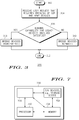
- FIG. 1 is a schematic diagram illustrating a system 100 in which an exemplary UPnP device 102 (e.g., an audio/visual server) and an exemplary SIP device 104 (e.g. , a cordless phone) are attempting to communicate.
- an exemplary UPnP device 102 e.g., an audio/visual server
- an exemplary SIP device 104 e.g. , a cordless phone
- SIP extensions e.g ., Session Initiation Protocol for Instant Messaging and Presence Leveraging Extensions, or SIMPLE
- SIMPLE Session Initiation Protocol for Instant Messaging and Presence Leveraging Extensions
- a second approach requires either a UPnP stack on the SIP device 104, or a SIP stack on the UPnP device 102.
- a legacy SIP device is a single-mode device that only supports the Internet Engineering Task Force (IETF) Request for Comments (RFC) 3261 SIP features.
- a legacy UPnP device is a single-mode device that only supports UPnP capabilities as specified by Digital Living Network Alliance (DLNA) 1.0 guidelines.
- FIG. 2 is a schematic diagram illustrating one embodiment of a system 200 for bridging Session Initiation Protocol and Universal Plug and Play devices.
- a legacy UPnP device 202 e.g ., an audio/visual server
- a legacy SIP device 204 e.g. , a cordless phone
- communicate via a software bridge 206 for example embodied in a personal computer, a residential gateway, a cellular telephone, or in a dedicated, standalone device ( e.g ., a set top box).
- the software bridge 206 operates transparently.
- the software bridge 206 makes the legacy SIP device 204 look transparent to the legacy UPnP device 202, and vice versa, so that the legacy SIP device 204 and the legacy UPnP device 202 operate as they normally would.
- the legacy SIP device 204 and the legacy UPnP device 202 may communicate directly or communicate using the software bridge 206 as an intermediary.
- the software bridge 206 relies on overloading the features of RFC 3261 SIP and on common applications. No additional protocol features, changes to the SIP specification or new application features are required for the software bridge 206 to successfully allow the legacy UPnP device 202 and the legacy SIP device 204 to communicate. As also discussed further below, the software bridge 206 enables the legacy UPnP device 202 to access session services by relaying session services offered by the legacy SIP device 204 to the UPnP network, thus facilitating bidirectional internetworking.
- FIG. 3 is a flow diagram illustrating one embodiment of a method 300 for bridging Session Initiation Protocol and Universal Plug and Play devices.
- the method 300 thus illustrates the functionality of the transparent software bridge 206 illustrated in FIG. 2 , and may therefore be implemented, for example, at a residential gateway or at a standalone accessory to an SIP device.
- the method 300 is initialized at step 302 and proceeds to step 304, where the software bridge receives a user request that requires the bridging of at least one SIP device and at least one UPnP device.
- the user may want to stream music from a UPnP-based home media server to an SIP cordless phone.
- the software bridge determines whether the minimal capability for legacy devices involved in the requested action in the request action is satisfied.
- a legacy SIP device is a single-mode device that only supports RFC3261 SIP features
- a legacy UPnP device is a single-mode device that only supports UPnP capabilities as specified by DLNA 1.0 guidelines.
- step 306 If the software bridge concludes in step 306 that the minimal capability for the legacy devices involved in the requested action is not satisfied, the method 300 proceeds to step 310, and the software bridge bridges the devices normally (e.g ., via a home gateway, SIP stack on UPnP device or UPnP stack on SIP device) before terminating in step 312.
- the software bridge bridges the devices normally (e.g ., via a home gateway, SIP stack on UPnP device or UPnP stack on SIP device) before terminating in step 312.
- step 306 the software bridge concludes in step 306 that the minimal capability for the legacy devices involved in the requested action is satisfied
- the method 300 proceeds to step 308, and the software bridge bridges the devices transparently (i.e ., substantially without impact to the operation, behavior or configuration of the bridged devices) before the method 300 terminates in step 312.
- FIG. 4 is a flow diagram illustrating a more detailed embodiment of a method 400 for bridging Session Initiation Protocol and Universal Plug and Play devices.
- the method 400 may be implemented in a software bridge embodied, for example, in a residential gateway or at a standalone accessory to an SIP device.
- the method 400 is specifically directed to enabling an SIP device to access UPnP services.
- the method 400 may be implemented by a user in order to stream music from a UPnP-based home media server to an SIP cordless phone.
- the method 400 is initialized at step 402 and proceeds to step 404, where the software bridge discovers UPnP devices and their services. Following discovery, the method 400 proceeds to step 406, and the software bridge associates a User Service Request Address (USRA) with each discovered UPnP device and the UPnP device's services.
- USRA User Service Request Address
- the USRA is a novel address format that reuses the format of the SIP Uniform Resource Identifier (URI), which enables standard RFC3261 SIP procedures to be used without making changes to the SIP or UPnP devices.
- URI Uniform Resource Identifier
- the USRA is used to address services offered by a bridge.
- the USRA comprises a domain (e.g ., the SIP domain "JohnsHome.net”), a device ID (e.g ., "JohnPC”) and a service ID (e.g ., "StreamMusic").
- a domain e.g ., the SIP domain "JohnsHome.net”
- a device ID e.g ., "JohnPC”
- a service ID e.g ., "StreamMusic”
- the software bridge registers, locates and, invokes at least one UPnP service, using the semantics of the SIP-URI.
- Registering UPnP services e.g ., by making connections between UPnP services and SIP URIs
- UPnP services e.g ., by making connections between UPnP services and SIP URIs
- SIP ID's e.g ., SIP URIs
- Registration also enables locating UPnP services (e.g ., by determining where/to which domain to route commands), which in turn enables access to services.
- Invoking UPnP services involves determining which UPnP service a command is requesting and generating a set of actions to be carried out by the UPnP device hosting the UPnP service to be accessed.
- One embodiment of a method for registering, locating and invoking a UPnP service is illustrated in FIG. 6 .
- the SIP-URI is used to register and locate UPnP services, rather than to register and locate users.
- the "To" field of an RFC3261 SIP header is used in a REGISTER method, in order to allow the software bridge to specify a UPnP service that needs to be registered in the SIP domain.
- usage of the "To" field is "overloaded” to address or register a service offered by a bridge, by including a USRA referring to the service.
- the "To" field in a RFC3261 SIP header is used to address or register users, as described above.
- the "To" field of an RFC3261 SIP header is used in an INVITE method, in order to allow an SIP device to locate a UPnP service.
- This also allows the software bridge to implement the UPnP service in terms of the UPnP actions.
- an SIP INVITE message with the "To" field set as described above is generated (e.g ., "To: JohnPC.StreamMusic@JohnsHome.net” or “To: DVR.StreamVideo@JohnsHome.net”).
- the "To” field is used by the software bridge to determined and invoke the service.
- the software bridge will recognize the UPnP domain (e.g ., "JohnsHome.net”) as a place to communicate with SIP devices.
- the "To" field of an RFC3261 SIP header is used in an INVITE method message, in order to allow an SIP device to call media items or to receive particular files or services.
- This also allows system elements of the software bridge to understand the methods to use, determined by the media resource attributes. For example, if a .cal extension calendar resource were called, the software bridge would create a rendered image of the calendar, to be streamed to the SIP device. As another example, if a .wav extension resource, the software bridge would stream the music to the SIP device.
- the "StreamVideo" portion of the exemplary USRA is used by the software bridge to select streaming video from the UPnP device to be sent to the SIP device.
- the method 400 then terminates in step 410.
- the method 400 thus relies on the re-use (overloading) of existing RFC3261 SIP and UPnP communication messages and on common applications (e.g ., an existing contact book application, an RFC2833-compliant dual-tone multi-frequency (DTMF) application on an SIP communication device or the like) to configure a USRA on a SIP device.
- common applications e.g ., an existing contact book application, an RFC2833-compliant dual-tone multi-frequency (DTMF) application on an SIP communication device or the like
- DTMF dual-tone multi-frequency
- the invention is extensible to legacy SIP and UPnP devices.
- UPnP applications are now accessible using SIP devices.
- the invention enables a UPnP device to access the session services, thus facilitating bidirectional internetworking.
- FIG. 6 is a flow diagram illustrating one embodiment of a method 600 for registering, locating and invoking a UPnP service (e.g ., in accordance with step 408 of the method 400).
- the method 600 is initialized at step 602 and proceeds to step 604, where the software bridge receives a command including a USRA from a SIP device.
- the command may be a SIP REGISTER command with the "To" field of the RFC3261 SIP header set as "To: JohnPC.StreamMusic@JohnsHome.net”.
- step 606 the software bridge identifies the service being requested by the command (e.g ., StreamMusic in the above example) and the UPnP device from which the service is requested (e.g ., JohnPC in the above example), in accordance with the USRA.
- the domain specified in the USRA tells the software bridge where to route the command.
- the software bridge maps the requested service to a set (i.e ., one or more) of actions or services.
- a set i.e ., one or more
- the StreamMusic service requested by the command might map to a series of actions including: (1) "browse” (e.g ., browse the music available at the UPnP device); (2) “select” ( e.g ., select an item from the available music); and (3) “play” (e.g ., play the selected item).
- step 610 the software bridge issues one or more commands (in UPnP format) to the identified UPnP device to execute the set of actions or services.
- the software bridge then receives a response from the identified UPnP device in step 612. For instance, if the software bridge issued a command to the UPnP device to "browse" in step 610, the UPnP device might respond in step 612 with a list of available music.
- the software bridge provides the requested service to the requestor/SIP device.
- the software bridge might provide the list of songs available from the identified UPnP device, so that the requestor may browse the list and make a selection.
- the method 600 terminates in step 616.
- FIG. 5 is a flow diagram illustrating a more detailed embodiment of a method 500 for bridging Session Initiation Protocol and Universal Plug and Play devices.
- the method 500 may be implemented at a software bridge, for example embodied in a residential gateway or at a standalone accessory to an SIP device.
- the method 500 is specifically directed to enabling a UPnP device to access session-based services offered by an SIP device.
- the method 500 may be implemented by a user in order to stream video from a UPnP media server onto an SIP cordless phone, using a UPnP enabled television remote control.
- the method 500 may be implemented by a user in order to use a SIP device to retrieve content stored on a UPnP media server and stream the retrieved content onto the SIP device.
- the method 500 is initialized at step 502 and proceeds to step 504, where the software bridge represents the SIP device to the UPnP network as a "virtual" UPnP audio/visual (AV) renderer device, hosted by the software bridge. That is, the software bridge appears as a UPnP device to the UPnP network.
- the "virtual" UPnP renderer is an alias for the SIP device, which represents the SIP device in the UPnP domain (whereas a "real" UPnP device has UPnP software and a UPnP identifier and communicates with the rest of the UPnP network using UPnP protocol).
- the software bridge is configured by determining which SIP devices are available to provide services and creating proxies (virtual UPnP devices) for each available SIP device.
- the "virtual" UPnP renderer advertises its presence on the UPnP network, so that the "virtual" UPnP renderer device is discoverable by legacy UPnP control points.
- the legacy UPnP control points may involve the "virtual" UPnP renderer device in a session with a legacy UPnP media server.
- the software bridge maps the UPnP AV renderer operations to SIP messages. For instance, upon discovery by a legacy UPnP control point, the software bridge may map UPnP signaling messages related to session establishment to SIP signaling messages. In further embodiments ( e.g ., involving UPnP control point initiated sessions), the UPnP AVT Play message is mapped to a SIP INVITE message, such that a SIP/UPnP session manager component of a bridge may take inputs from the "virtual" UPnP renderer in order to perform mapping operations.
- a SIP INVITE message is mapped to a set of UPnP actions (e.g ., UPnP CDS Browse, UPnP AVT SetTransport URI, UPnP AVT Play or the like), and the SIP/UPnP session manager component of the software bridge performs the mapping operations.
- UPnP actions e.g ., UPnP CDS Browse, UPnP AVT SetTransport URI, UPnP AVT Play or the like
- the SIP/UPnP session manager component of the software bridge performs the mapping operations.
- a SIP session is initiated once the "virtual" UPnP renderer completes a download of the media session over hypertext transport protocol (HTTP).
- HTTP hypertext transport protocol
- a UPnP Content Directory Service could be used by using a GetProtocolInfo() message in order to obtain a protocol/format list for an SIP device.
- the "virtual" UPnP renderer has SIP to UPnP protocol mapping functionality. In a further embodiment still, the "virtual" UPnP renderer has media transcoding functionality.
- the method 500 terminates in step 508.
- the method 500 therefore allows devices that cannot normally interact directly (e.g ., UPnP media servers/control points and SIP devices) to interact via a "virtual" UPnP renderer acting on behalf of the SIP device.
- the "virtual" UPnP renderer may be placed on the media path. Such placement may support valuable applications, such as the ability to perform real-time transcoding when there is a mismatch in codec abilities between a UPnP media server and a SIP device.
- FIG. 7 is a high level block diagram of the present software bridge that is implemented using a general purpose computing device 700, such as a personal computer, a set top box, a residential gateway, a mobile telephone, a personal digital assistant or the like.
- a general purpose computing device 700 comprises a processor 702, a memory 704, a bridge module 705 and various input/output (I/O) devices 706 such as a display, a keyboard, a mouse, a modem, a network connection and the like.
- I/O device is a storage device (e.g ., a disk drive, an optical disk drive, a floppy disk drive).
- the bridge module 705 can be implemented as a physical device or subsystem that is coupled to a processor through a communication channel.
- the bridge module 705 can be represented by one or more software applications (or even a combination of software and hardware, e.g ., using Application Specific Integrated Circuits (ASIC)), where the software is loaded from a storage medium (e.g ., I/O devices 706) and operated by the processor 702 in the memory 704 of the general purpose computing device 700. Additionally, the software may run in a distributed or partitioned fashion on two or more computing devices similar to the general purpose computing device 700.
- the bridge module 705 for bridging SIP and UPnP devices described herein with reference to the preceding figures can be stored on a computer readable medium or carrier (e.g ., RAM, magnetic or optical drive or diskette, and the like).
- the present invention represents a significant advancement in the field of home and mobile networking applications.
- Embodiments of the invention rely on overloading the features of RFC 3261 SIP and on common applications. No additional protocol features, changes to the SIP specification or new application features are needed.
- the invention is extensible to legacy SIP and UPnP devices.
- the invention enables a UPnP device to access the session services, thus facilitating bidirectional internetworking.
Description
- The present invention generally relates to home and mobile networking applications, and more particularly relates to Session Initiation Protocol and Universal Plug and Play technologies.
- Session Initiation Protocol (SIP) and Universal Plug and Play (UPnP) are two protocols that are widely deployed in home and mobile networking applications. While UPnP is traditionally popular in the home consumer space, SIP tends to be popular in both home and mobile environments. Although attempts have been made to bridge the SIP and UPnP technologies, such attempts have been limited by the capabilities of the devices.
-
FIG. 1 , for example, is a schematic diagram illustrating asystem 100 in which an exemplary UPnP device 102 (e.g., an audio/visual server) and an exemplary SIP device 104 (e.g., a cordless phone) are attempting to communicate. One approach in which theSIP device 104 and the UPnPdevice 102 may be bridged is via a home gateway that requires SIP extensions (e.g., Session Initiation Protocol for Instant Messaging and Presence Leveraging Extensions, or SIMPLE) on theSIP device 104. A second approach requires either a UPnP stack on theSIP device 104, or a SIP stack on theUPnP device 102. Thus, existing solutions are limited to situations in which the end device(s) have a required capability even to enable minimal interoperability. In other words, these solutions are not extensible to legacy devices that may already be deployed in a user's network. A legacy SIP device is a single-mode device that only supports the Internet Engineering Task Force (IETF) Request for Comments (RFC) 3261 SIP features. A legacy UPnP device is a single-mode device that only supports UPnP capabilities as specified by Digital Living Network Alliance (DLNA) 1.0 guidelines. - Moreover, existing approaches to bridging the SIP and UPnP technologies typically do not support bidirectional internetworking, see the patent publication
US 2006/013392 A1 . That is, while the approaches enable an SIP device (with extensions) to access UPnP services, no attempts have been made to make a service offered by a user communication device (e.g., an SIP device) accessible to a UPnP network. - Therefore, there is a need in the art for a method and apparatus for bridging Session Initiation Protocol and Universal Plug and Play devices.
- So that the manner in which the above recited embodiments of the invention are attained and can be understood in detail, a more particular description of the invention may be had by reference to the embodiments thereof which are illustrated in the appended drawings. It is to be noted, however, that the appended drawings illustrate only typical embodiments of this invention and are therefore not to be considered limiting of its scope, for the invention may admit to other equally effective embodiments. The invention is defined in independent claims 1, 14 and 20.
-
FIG. 1 is a schematic diagram illustrating a system in which an exemplary UPnP device and an exemplary SIP device are attempting to communicate; -
FIG. 2 is a schematic diagram illustrating one embodiment of a system for bridging Session Initiation Protocol and Universal Plug and Play devices -
FIG. 3 is a flow diagram illustrating one embodiment of a method for bridging Session Initiation Protocol and Universal Plug and Play devices; -
FIG. 4 is a flow diagram illustrating a more detailed embodiment of a method for bridging Session Initiation Protocol and Universal Plug and Play devices; -
FIG. 5 is a flow diagram illustrating a more detailed embodiment of a method for bridging Session Initiation Protocol and Universal Plug and Play devices; -
FIG. 6 is a flow diagram illustrating one embodiment of a method for registering, locating and invoking a UPnP service; and -
FIG. 7 is a high level block diagram of the present software bridge that is implemented using a general purpose computing device. - To facilitate understanding, identical reference numerals have been used, where possible, to designate identical elements that are common to the figures.
-
FIG. 2 is a schematic diagram illustrating one embodiment of asystem 200 for bridging Session Initiation Protocol and Universal Plug and Play devices. In the illustrated embodiment, a legacy UPnP device 202 (e.g., an audio/visual server) and a legacy SIP device 204 (e.g., a cordless phone) communicate via asoftware bridge 206, for example embodied in a personal computer, a residential gateway, a cellular telephone, or in a dedicated, standalone device (e.g., a set top box). Thesoftware bridge 206 operates transparently. That is, thesoftware bridge 206 makes thelegacy SIP device 204 look transparent to the legacy UPnPdevice 202, and vice versa, so that thelegacy SIP device 204 and the legacy UPnPdevice 202 operate as they normally would. Once thesoftware bridge 206 is implemented, thelegacy SIP device 204 and the legacy UPnPdevice 202 may communicate directly or communicate using thesoftware bridge 206 as an intermediary. - As described in further detail below, the
software bridge 206 relies on overloading the features of RFC 3261 SIP and on common applications. No additional protocol features, changes to the SIP specification or new application features are required for thesoftware bridge 206 to successfully allow the legacy UPnPdevice 202 and thelegacy SIP device 204 to communicate. As also discussed further below, thesoftware bridge 206 enables the legacy UPnPdevice 202 to access session services by relaying session services offered by thelegacy SIP device 204 to the UPnP network, thus facilitating bidirectional internetworking. -
FIG. 3 is a flow diagram illustrating one embodiment of amethod 300 for bridging Session Initiation Protocol and Universal Plug and Play devices. Themethod 300 thus illustrates the functionality of thetransparent software bridge 206 illustrated inFIG. 2 , and may therefore be implemented, for example, at a residential gateway or at a standalone accessory to an SIP device. - The
method 300 is initialized atstep 302 and proceeds tostep 304, where the software bridge receives a user request that requires the bridging of at least one SIP device and at least one UPnP device. For example, the user may want to stream music from a UPnP-based home media server to an SIP cordless phone. - In
step 306, the software bridge determines whether the minimal capability for legacy devices involved in the requested action in the request action is satisfied. As described above, a legacy SIP device is a single-mode device that only supports RFC3261 SIP features, and a legacy UPnP device is a single-mode device that only supports UPnP capabilities as specified by DLNA 1.0 guidelines. - If the software bridge concludes in
step 306 that the minimal capability for the legacy devices involved in the requested action is not satisfied, themethod 300 proceeds tostep 310, and the software bridge bridges the devices normally (e.g., via a home gateway, SIP stack on UPnP device or UPnP stack on SIP device) before terminating instep 312. - Alternatively, if the software bridge concludes in
step 306 that the minimal capability for the legacy devices involved in the requested action is satisfied, themethod 300 proceeds tostep 308, and the software bridge bridges the devices transparently (i.e., substantially without impact to the operation, behavior or configuration of the bridged devices) before themethod 300 terminates instep 312. -
FIG. 4 is a flow diagram illustrating a more detailed embodiment of amethod 400 for bridging Session Initiation Protocol and Universal Plug and Play devices. Like themethod 300, themethod 400 may be implemented in a software bridge embodied, for example, in a residential gateway or at a standalone accessory to an SIP device. Themethod 400 is specifically directed to enabling an SIP device to access UPnP services. Thus, for example, themethod 400 may be implemented by a user in order to stream music from a UPnP-based home media server to an SIP cordless phone. - The
method 400 is initialized atstep 402 and proceeds tostep 404, where the software bridge discovers UPnP devices and their services. Following discovery, themethod 400 proceeds tostep 406, and the software bridge associates a User Service Request Address (USRA) with each discovered UPnP device and the UPnP device's services. The USRA is a novel address format that reuses the format of the SIP Uniform Resource Identifier (URI), which enables standard RFC3261 SIP procedures to be used without making changes to the SIP or UPnP devices. However, where the SIP URI is used for addressing users (e.g., the users of services), the USRA is used to address services offered by a bridge. For example, abstract services (e.g., UPnP application handles, such as "StreamMusic") are mapped to executable UPnP actions or sequences of UPnP actions for use by SIP users, by reusing the SIP URI. In one embodiment, the USRA comprises a domain (e.g., the SIP domain "JohnsHome.net"), a device ID (e.g., "JohnPC") and a service ID (e.g., "StreamMusic"). - In
step 408, the software bridge registers, locates and, invokes at least one UPnP service, using the semantics of the SIP-URI. Registering UPnP services (e.g., by making connections between UPnP services and SIP URIs) enables UPnP services to be accessed from an SIP domain using regular SIP ID's (e.g., SIP URIs). Registration also enables locating UPnP services (e.g., by determining where/to which domain to route commands), which in turn enables access to services. Invoking UPnP services involves determining which UPnP service a command is requesting and generating a set of actions to be carried out by the UPnP device hosting the UPnP service to be accessed. One embodiment of a method for registering, locating and invoking a UPnP service is illustrated inFIG. 6 . Thus, the SIP-URI is used to register and locate UPnP services, rather than to register and locate users. - For example, in one embodiment, the "To" field of an RFC3261 SIP header is used in a REGISTER method, in order to allow the software bridge to specify a UPnP service that needs to be registered in the SIP domain. In particular, usage of the "To" field is "overloaded" to address or register a service offered by a bridge, by including a USRA referring to the service. Normally, the "To" field in a RFC3261 SIP header is used to address or register users, as described above.
- For instance, say a user, John, would like to use his SIP device to stream a song stored in the default shared folder of his UPnP media server (hosted by a PC in John's room, with the UPnP friendly name "JohnPC"). Further assume that the software bridge has a service titled "StreamMusic" that supports this scenario. In this case, the software bridge would execute an SIP REGISTER with the "To" field of the RFC3261 SIP header set as "To: JohnPC.StreamMusic@JohnsHome.net", where "JohnsHome.net is the SIP domain that provides the "StreamMusic" service. The software bridge will recognize the UPnP device "JohnsPC" as a device that is allowed to communicate with SIP-based devices.
- Alternatively, suppose John wants to use his SIP device to stream a video clip stored in the default shared folder of his digital video recorder (which has the UPnP friendly name "DVR"). Further assume that the software bridge has a service titled "StreamVideo" that supports this scenario. In this case, the software bridge would execute an SIP REGISTER with the "To" field of the RFC3261 SIP header set as "To: DVR.StreamVideo@JohnsHome.net".
- In another embodiment, the "To" field of an RFC3261 SIP header is used in an INVITE method, in order to allow an SIP device to locate a UPnP service. This also allows the software bridge to implement the UPnP service in terms of the UPnP actions. Referring back to the example above, when John actually invokes a service from his SIP device, an SIP INVITE message with the "To" field set as described above is generated (e.g., "To: JohnPC.StreamMusic@JohnsHome.net" or "To: DVR.StreamVideo@JohnsHome.net"). The "To" field is used by the software bridge to determined and invoke the service. The software bridge will recognize the UPnP domain (e.g., "JohnsHome.net") as a place to communicate with SIP devices.
- In yet another embodiment, the "To" field of an RFC3261 SIP header is used in an INVITE method message, in order to allow an SIP device to call media items or to receive particular files or services. This also allows system elements of the software bridge to understand the methods to use, determined by the media resource attributes. For example, if a .cal extension calendar resource were called, the software bridge would create a rendered image of the calendar, to be streamed to the SIP device. As another example, if a .wav extension resource, the software bridge would stream the music to the SIP device. In this case, the "StreamVideo" portion of the exemplary USRA is used by the software bridge to select streaming video from the UPnP device to be sent to the SIP device.
- The
method 400 then terminates instep 410. - The
method 400 thus relies on the re-use (overloading) of existing RFC3261 SIP and UPnP communication messages and on common applications (e.g., an existing contact book application, an RFC2833-compliant dual-tone multi-frequency (DTMF) application on an SIP communication device or the like) to configure a USRA on a SIP device. No additional protocol features (e.g., SIMPLE), changes to the SIP specification or new application features are needed, making the overloading transparent to software and hardware. Thus, the invention is extensible to legacy SIP and UPnP devices. However, from an end-user perspective, UPnP applications are now accessible using SIP devices. Moreover, by relaying session services offered by an SIP device to a UPnP network, the invention enables a UPnP device to access the session services, thus facilitating bidirectional internetworking. -
FIG. 6 is a flow diagram illustrating one embodiment of amethod 600 for registering, locating and invoking a UPnP service (e.g., in accordance withstep 408 of the method 400). - The
method 600 is initialized atstep 602 and proceeds to step 604, where the software bridge receives a command including a USRA from a SIP device. For example, the command may be a SIP REGISTER command with the "To" field of the RFC3261 SIP header set as "To: JohnPC.StreamMusic@JohnsHome.net". - In
step 606, the software bridge identifies the service being requested by the command (e.g., StreamMusic in the above example) and the UPnP device from which the service is requested (e.g., JohnPC in the above example), in accordance with the USRA. The domain specified in the USRA tells the software bridge where to route the command. - In
step 608, the software bridge maps the requested service to a set (i.e., one or more) of actions or services. For instance, in the above example, the StreamMusic service requested by the command might map to a series of actions including: (1) "browse" (e.g., browse the music available at the UPnP device); (2) "select" (e.g., select an item from the available music); and (3) "play" (e.g., play the selected item). - In
step 610, the software bridge issues one or more commands (in UPnP format) to the identified UPnP device to execute the set of actions or services. The software bridge then receives a response from the identified UPnP device instep 612. For instance, if the software bridge issued a command to the UPnP device to "browse" instep 610, the UPnP device might respond instep 612 with a list of available music. - In
step 614, the software bridge provides the requested service to the requestor/SIP device. For instance, the software bridge might provide the list of songs available from the identified UPnP device, so that the requestor may browse the list and make a selection. - The
method 600 terminates instep 616. -
FIG. 5 is a flow diagram illustrating a more detailed embodiment of amethod 500 for bridging Session Initiation Protocol and Universal Plug and Play devices. Like themethod 300, themethod 500 may be implemented at a software bridge, for example embodied in a residential gateway or at a standalone accessory to an SIP device. Themethod 500 is specifically directed to enabling a UPnP device to access session-based services offered by an SIP device. Thus, for example, themethod 500 may be implemented by a user in order to stream video from a UPnP media server onto an SIP cordless phone, using a UPnP enabled television remote control. Alternatively, themethod 500 may be implemented by a user in order to use a SIP device to retrieve content stored on a UPnP media server and stream the retrieved content onto the SIP device. - The
method 500 is initialized atstep 502 and proceeds to step 504, where the software bridge represents the SIP device to the UPnP network as a "virtual" UPnP audio/visual (AV) renderer device, hosted by the software bridge. That is, the software bridge appears as a UPnP device to the UPnP network. Thus, the "virtual" UPnP renderer is an alias for the SIP device, which represents the SIP device in the UPnP domain (whereas a "real" UPnP device has UPnP software and a UPnP identifier and communicates with the rest of the UPnP network using UPnP protocol). In one embodiment, the software bridge is configured by determining which SIP devices are available to provide services and creating proxies (virtual UPnP devices) for each available SIP device. In accordance withstep 502, the "virtual" UPnP renderer advertises its presence on the UPnP network, so that the "virtual" UPnP renderer device is discoverable by legacy UPnP control points. Once the "virtual" UPnP renderer device is discovered, the legacy UPnP control points may involve the "virtual" UPnP renderer device in a session with a legacy UPnP media server. - In
step 506, the software bridge maps the UPnP AV renderer operations to SIP messages. For instance, upon discovery by a legacy UPnP control point, the software bridge may map UPnP signaling messages related to session establishment to SIP signaling messages. In further embodiments (e.g., involving UPnP control point initiated sessions), the UPnP AVT Play message is mapped to a SIP INVITE message, such that a SIP/UPnP session manager component of a bridge may take inputs from the "virtual" UPnP renderer in order to perform mapping operations. In another embodiment (e.g., involving a SIP device initiated session), a SIP INVITE message is mapped to a set of UPnP actions (e.g., UPnP CDS Browse, UPnP AVT SetTransport URI, UPnP AVT Play or the like), and the SIP/UPnP session manager component of the software bridge performs the mapping operations. In another embodiment still (e.g., involving a UPnP control point initiated session), a SIP session is initiated once the "virtual" UPnP renderer completes a download of the media session over hypertext transport protocol (HTTP). - In one embodiment, a UPnP Content Directory Service could be used by using a GetProtocolInfo() message in order to obtain a protocol/format list for an SIP device. In one embodiment, the "virtual" UPnP renderer has SIP to UPnP protocol mapping functionality. In a further embodiment still, the "virtual" UPnP renderer has media transcoding functionality.
- The
method 500 terminates instep 508. - The
method 500 therefore allows devices that cannot normally interact directly (e.g., UPnP media servers/control points and SIP devices) to interact via a "virtual" UPnP renderer acting on behalf of the SIP device. In further embodiments, the "virtual" UPnP renderer may be placed on the media path. Such placement may support valuable applications, such as the ability to perform real-time transcoding when there is a mismatch in codec abilities between a UPnP media server and a SIP device. -
FIG. 7 is a high level block diagram of the present software bridge that is implemented using a generalpurpose computing device 700, such as a personal computer, a set top box, a residential gateway, a mobile telephone, a personal digital assistant or the like. In one embodiment, a generalpurpose computing device 700 comprises aprocessor 702, amemory 704, abridge module 705 and various input/output (I/O)devices 706 such as a display, a keyboard, a mouse, a modem, a network connection and the like. In one embodiment, at least one I/O device is a storage device (e.g., a disk drive, an optical disk drive, a floppy disk drive). It should be understood that thebridge module 705 can be implemented as a physical device or subsystem that is coupled to a processor through a communication channel. - Alternatively, the
bridge module 705 can be represented by one or more software applications (or even a combination of software and hardware, e.g., using Application Specific Integrated Circuits (ASIC)), where the software is loaded from a storage medium (e.g., I/O devices 706) and operated by theprocessor 702 in thememory 704 of the generalpurpose computing device 700. Additionally, the software may run in a distributed or partitioned fashion on two or more computing devices similar to the generalpurpose computing device 700. Thus, in one embodiment, thebridge module 705 for bridging SIP and UPnP devices described herein with reference to the preceding figures can be stored on a computer readable medium or carrier (e.g., RAM, magnetic or optical drive or diskette, and the like). - Thus, the present invention represents a significant advancement in the field of home and mobile networking applications. Embodiments of the invention rely on overloading the features of RFC 3261 SIP and on common applications. No additional protocol features, changes to the SIP specification or new application features are needed. Thus, the invention is extensible to legacy SIP and UPnP devices. Moreover, by relaying session services offered by an SIP device to a UPnP network, the invention enables a UPnP device to access the session services, thus facilitating bidirectional internetworking.
- While the foregoing is directed to embodiments of the invention, other and further embodiments of the invention may be devised without departing from the basic scope thereof, as defined by the claims.
Claims (20)
- A method for bridging a session initiation protocol device (204) and a universal plug and play device (202), the method comprising:detecting that both of the session initiation protocol device and the universal plug and play device are legacy devices, the session initiation protocol device being a single-mode device that supports only session initiation protocol features as described in Request for Comments 3261 and the universal plug and play device being a single-mode device that supports only universal plug and play capabilities as specified in Digital Living Network Alliance 1.0 guidelines; andbridging the session initiation protocol device and the universal plug and play device using a bridge, the bridging comprising:for enabling the session initiation protocol device to access an universal plug and play service of the universal plug and play device, associating a User Service Request Address with the universal plug and play service of the universal plug and play device, the User Service Request Address reusing the format of a session initiation protocol Uniform Resource Identifier, and registering, in a session initiation protocol domain, by the bridge, the User Service Request Address; andfor enabling the universal plug and play device to access the session initiation protocol device, representing the session initiation protocol device as a virtual universal plug and play audio/visual renderer device.
- The method of claim 1, wherein the bridging further comprises:discovering at least one universal plug and play device, including one or more services associated with the at least one universal plug and play device; andassociating a user service request address with each discovered universal plug and play device and the discovered universal plug and play device's associated services, wherein each user service request address is an address format that reuses a format of an identifier of a session initiation protocol device.
- The method of claim 2, wherein each user service request address reuses a format of a session initiation protocol field as described in Request for Comments 3261.
- The method of claim 3, wherein the user service request address reuses a uniform resource identifier field.
- The method of claim 3, wherein the bridging further comprises:registering at least one universal plug and play service using semantics of a session initiation protocol uniform resource identifier.
- The method of claim 5, wherein a "To" field of a Request for Comments 3261 session initiation protocol header is used in a REGISTER method to specify a universal plug and play service for registration in a session initiation protocol domain.
- The method of claim 5, wherein the bridging further comprises:locating the least one universal plug and play service using the semantics of the session initiation protocol uniform resource identifier.
- The method of claim 7, wherein a "To" field of a Request for Comments 3261 session initiation protocol header is used in an INVITE method to enable the session initiation protocol device to locate the at least one universal plug and play service.
- The method of claim 7, wherein the bridging further comprises:invoking the least one universal plug and play service using the semantics of the session initiation protocol uniform resource identifier.
- The method of claim 9, wherein a "To" field of a Request for Comments 3261 session initiation protocol header is used in an INVITE method to enable the session initiation protocol device to call at least one media item.
- The method of claim 9, wherein the invoking comprises:generating a set of one or more actions for the at least one universal plug and play device to perform.
- The method of claim 1, wherein the bridging further comprises:mapping at least one operation of the universal plug and play device to at least one session initiation protocol message.
- The method of claim 12, wherein a universal plug and play GetProtocolInfo() message is used to obtain a protocol/format list of the session initiation protocol device.
- A computer readable medium containing an executable program for bridging a session initiation protocol device and a universal plug and play device, where the executable program comprises instructions for:detecting that both of the session initiation protocol device and the universal plug and play device are legacy devices, the session initiation protocol device being a single-mode device that supports only session initiation protocol features as described in Request for Comments 3261 and the universal plug and play device being a single-mode device that supports only universal plug and play capabilities as specified in Digital Living Network Alliance 1.0 guidelines; andbridging the session initiation protocol device and the universal plug and play device using a bridge, the bridging comprising:for enabling the session initiation protocol device to access an universal plug and play service of the universal plug and play device, associating a User Service Request Address with the universal plug and play service of the universal plug and play device, the User Service Request Address reusing the format of a session initiation protocol Uniform Resource Identifier, and registering, in a session initiation protocol domain, by the bridge, the User Service Request Address; andfor enabling the universal plug and play device to access the session initiation protocol device, representing the session initiation protocol device as a virtual universal plug and play audio/visual renderer device.
- The computer readable medium of claim 14, wherein the bridging allows the session initiation protocol device to access at least one universal plug and play service.
- The computer readable medium of claim 15, wherein the bridging further comprises:discovering at least one universal plug and play device, including one or more services associated with the at least one universal plug and play device; andassociating a user service request address with each discovered universal plug and play device and the discovered universal plug and play device's associated services, wherein each user service request address is an address format that reuses a format of an identifier of a session initiation protocol device.
- The computer readable medium of claim 16, wherein each user service request address reuses a format of a session initiation protocol field as described in Request for Comments 3261.
- The computer readable medium of claim 17, wherein the bridging further comprises:registering at least one universal plug and play service using semantics of a session initiation protocol uniform resource identifier;locating the least one universal plug and play service using the semantics of the session initiation protocol uniform resource identifier; andinvoking the least one universal plug and play service using the semantics of the session initiation protocol uniform resource identifier.
- The computer readable medium of claim 14, wherein the bridging allows the universal plug and play device to access at least one session-based service offered by the session initiation protocol device.
- A system comprising:a session initiation protocol device (204), the session initiation protocol device being a single-mode device that supports only session initiation protocol features as described in Request for Comments 3261;a universal plug and play device (202), the universal plug and play device being a single-mode device that supports only universal plug and play capabilities as specified in Digital Living Network Alliance 1.0 guidelines, and a bridge (206) adapted to bridge together the session initiation protocol device and the universal plug and play device, the bridge being adapted for for enabling the session initiation protocol device to access an universal plug and play service of the universal plug and play device, associating a User Service Request Address with the universal plug and play service of the universal plug and play device, the User Service Request Address reusing the format of a session initiation protocol Uniform Resource Identifier, and registering, in a session initiation protocol domain, by the bridge, the User Service Request Address; andfor enabling the universal plug and play device to access the session initiation protocol device, representing the session initiation protocol device as a virtual universal plug and play audio/visual renderer device.
Applications Claiming Priority (2)
| Application Number | Priority Date | Filing Date | Title |
|---|---|---|---|
| US11/969,648 US8873570B2 (en) | 2008-01-04 | 2008-01-04 | Extensible system and method to bridge SIP and UPnP devices |
| PCT/US2008/087926 WO2009088728A2 (en) | 2008-01-04 | 2008-12-22 | An extensible system and method to bridge sip and upnp devices |
Publications (2)
| Publication Number | Publication Date |
|---|---|
| EP2241038A2 EP2241038A2 (en) | 2010-10-20 |
| EP2241038B1 true EP2241038B1 (en) | 2018-02-21 |
Family
ID=40801948
Family Applications (1)
| Application Number | Title | Priority Date | Filing Date |
|---|---|---|---|
| EP08869321.3A Active EP2241038B1 (en) | 2008-01-04 | 2008-12-22 | An extensible system and method to bridge sip and upnp devices |
Country Status (3)
| Country | Link |
|---|---|
| US (1) | US8873570B2 (en) |
| EP (1) | EP2241038B1 (en) |
| WO (1) | WO2009088728A2 (en) |
Families Citing this family (12)
| Publication number | Priority date | Publication date | Assignee | Title |
|---|---|---|---|---|
| KR101512321B1 (en) * | 2007-08-22 | 2015-04-16 | 삼성전자주식회사 | / Method and apparatus for providing/receiving service of plurality of service providers |
| WO2009120030A2 (en) * | 2008-03-28 | 2009-10-01 | 삼성전자 주식회사 | Data receiving method and device for applications providing an iptv communications service |
| US9054891B2 (en) * | 2008-03-31 | 2015-06-09 | Google Technology Holdings LLC | Distributing session initiation protocol content to universal plug and play devices in a local network |
| US8010983B1 (en) * | 2008-07-02 | 2011-08-30 | Digital Keystone, Inc. | Method and apparatus for enabling switched video service on a host media server |
| US8151108B1 (en) | 2008-07-02 | 2012-04-03 | Digital Keystone, Inc. | Methods for establishing a secure channel of communications to enable switched video service on a host media server |
| US20110116540A1 (en) * | 2009-11-18 | 2011-05-19 | General Instrument Corporation | Multimedia Content Handling in a Home-Network System |
| CN102238136B (en) | 2010-04-26 | 2014-05-21 | 华为终端有限公司 | Method and device for transmitting media resource |
| US20110283276A1 (en) * | 2010-05-11 | 2011-11-17 | Carlton Andrews | System and Method for Automated Information Handling System Network Device Discovery and Support |
| KR101698354B1 (en) * | 2010-07-16 | 2017-01-23 | 삼성전자주식회사 | Apparatus and method for controlling a plurality of remote user interface servers in a home network |
| WO2012099370A2 (en) * | 2011-01-17 | 2012-07-26 | 엘지전자 주식회사 | Control apparatus, control target apparatus, and alarm-setting method using the apparatuses |
| US8873750B2 (en) | 2013-03-14 | 2014-10-28 | International Business Machines Corporation | Instruction for performing a pseudorandom number generate operation |
| EP3496357A1 (en) * | 2017-12-08 | 2019-06-12 | Cork Institute Of Technology | Method and device for enabling interoperability between networked iot devices in heterogeneous networks |
Citations (1)
| Publication number | Priority date | Publication date | Assignee | Title |
|---|---|---|---|---|
| US20060133392A1 (en) * | 2004-11-24 | 2006-06-22 | Kabushiki Kaisha Toshiba | Gateway device, network system, communication program, and communication method |
Family Cites Families (8)
| Publication number | Priority date | Publication date | Assignee | Title |
|---|---|---|---|---|
| US20020103898A1 (en) * | 2001-01-31 | 2002-08-01 | Moyer Stanley L. | System and method for using session initiation protocol (SIP) to communicate with networked appliances |
| US7761571B2 (en) | 2003-11-25 | 2010-07-20 | Panasonic Corporation | SIP service for home network device and service mobility |
| US20060153072A1 (en) * | 2004-12-28 | 2006-07-13 | Matsushita Electric Industrial Co., Ltd. | Extending universal plug and play messaging beyond a local area network |
| US20060140199A1 (en) * | 2004-12-28 | 2006-06-29 | Matsushita Electric Industrial Co., Ltd. | SIP/UPnP bridging middleware architecture for a service gateway framework |
| WO2007071282A1 (en) * | 2005-12-19 | 2007-06-28 | Telefonaktiebolaget L M Ericsson (Publ) | Method and apparatus for enabling discovery within a home network |
| ITTO20060083A1 (en) * | 2006-02-07 | 2007-08-08 | St Microelectronics Srl | "PLUG-AND-PLAY" DEVICE FOR VIDEO-VOICE APPLICATIONS ON PACKET-SWITCHED NETWORKS |
| CN101766004B (en) * | 2007-06-29 | 2012-09-19 | 意大利电信股份公司 | Method and system for the provision of communication session control in a local area network |
| EP2061216A1 (en) * | 2007-11-16 | 2009-05-20 | Nederlandse Organisatie voor toegepast-natuurwetenschappelijk Onderzoek TNO | Exchanging control codes between SIP/IMS and UPnP network elements. |
-
2008
- 2008-01-04 US US11/969,648 patent/US8873570B2/en active Active
- 2008-12-22 EP EP08869321.3A patent/EP2241038B1/en active Active
- 2008-12-22 WO PCT/US2008/087926 patent/WO2009088728A2/en active Application Filing
Patent Citations (1)
| Publication number | Priority date | Publication date | Assignee | Title |
|---|---|---|---|---|
| US20060133392A1 (en) * | 2004-11-24 | 2006-06-22 | Kabushiki Kaisha Toshiba | Gateway device, network system, communication program, and communication method |
Also Published As
| Publication number | Publication date |
|---|---|
| US8873570B2 (en) | 2014-10-28 |
| EP2241038A2 (en) | 2010-10-20 |
| US20090175296A1 (en) | 2009-07-09 |
| WO2009088728A3 (en) | 2009-09-03 |
| WO2009088728A2 (en) | 2009-07-16 |
Similar Documents
| Publication | Publication Date | Title |
|---|---|---|
| EP2241038B1 (en) | An extensible system and method to bridge sip and upnp devices | |
| US7783771B2 (en) | Network communication device for universal plug and play and internet multimedia subsystems networks | |
| US8194681B2 (en) | Bridging between AD HOC local networks and internet-based peer-to-peer networks | |
| US8356083B2 (en) | System and method for transmitting and receiving a call on a home network | |
| US9742851B2 (en) | Method and arrangement for remotely controlling multimedia communication across local networks | |
| US20070143488A1 (en) | Virtual universal plug and play control point | |
| US8787267B2 (en) | Technique for providing access to a media resource attached to a network-registered device | |
| US20090092109A1 (en) | Method and Apparatus for Enabling Discovery Within a Home Network | |
| JP2013225941A (en) | Service control device, service control system and method | |
| EP2144398A1 (en) | Method and apparatus for monitoring and logging communication sessions in a home network | |
| JP4044551B2 (en) | Gateway device, content providing server, communication program, and communication method | |
| Brown et al. | A SIP-based OSGi device communication service for mobile personal area networks. | |
| KR101329668B1 (en) | Contents sharing system and method using push server | |
| US20090292807A1 (en) | Multimedia data transferring method and system thereof | |
| JP5191878B2 (en) | Content transfer method and system for transmitting content from terminal in home network to wide area network | |
| Haber et al. | Virtualization of remote devices and services in residential networks | |
| Nakamoto et al. | Home Networking System with SIP |
Legal Events
| Date | Code | Title | Description |
|---|---|---|---|
| PUAI | Public reference made under article 153(3) epc to a published international application that has entered the european phase |
Free format text: ORIGINAL CODE: 0009012 |
|
| 17P | Request for examination filed |
Effective date: 20100804 |
|
| AK | Designated contracting states |
Kind code of ref document: A2 Designated state(s): AT BE BG CH CY CZ DE DK EE ES FI FR GB GR HR HU IE IS IT LI LT LU LV MC MT NL NO PL PT RO SE SI SK TR |
|
| AX | Request for extension of the european patent |
Extension state: AL BA MK RS |
|
| DAX | Request for extension of the european patent (deleted) | ||
| 17Q | First examination report despatched |
Effective date: 20130118 |
|
| RAP1 | Party data changed (applicant data changed or rights of an application transferred) |
Owner name: MOTOROLA MOBILITY LLC |
|
| RAP1 | Party data changed (applicant data changed or rights of an application transferred) |
Owner name: GOOGLE TECHNOLOGY HOLDINGS LLC |
|
| REG | Reference to a national code |
Ref country code: DE Ref legal event code: R079 Ref document number: 602008054148 Country of ref document: DE Free format text: PREVIOUS MAIN CLASS: H04J0003220000 Ipc: H04L0029080000 |
|
| GRAP | Despatch of communication of intention to grant a patent |
Free format text: ORIGINAL CODE: EPIDOSNIGR1 |
|
| RIC1 | Information provided on ipc code assigned before grant |
Ipc: H04L 29/06 20060101ALI20170905BHEP Ipc: H04L 29/08 20060101AFI20170905BHEP Ipc: H04L 12/28 20060101ALI20170905BHEP |
|
| INTG | Intention to grant announced |
Effective date: 20170925 |
|
| GRAS | Grant fee paid |
Free format text: ORIGINAL CODE: EPIDOSNIGR3 |
|
| GRAA | (expected) grant |
Free format text: ORIGINAL CODE: 0009210 |
|
| AK | Designated contracting states |
Kind code of ref document: B1 Designated state(s): AT BE BG CH CY CZ DE DK EE ES FI FR GB GR HR HU IE IS IT LI LT LU LV MC MT NL NO PL PT RO SE SI SK TR |
|
| REG | Reference to a national code |
Ref country code: GB Ref legal event code: FG4D |
|
| REG | Reference to a national code |
Ref country code: CH Ref legal event code: EP |
|
| REG | Reference to a national code |
Ref country code: AT Ref legal event code: REF Ref document number: 972897 Country of ref document: AT Kind code of ref document: T Effective date: 20180315 |
|
| REG | Reference to a national code |
Ref country code: IE Ref legal event code: FG4D |
|
| REG | Reference to a national code |
Ref country code: DE Ref legal event code: R096 Ref document number: 602008054148 Country of ref document: DE |
|
| REG | Reference to a national code |
Ref country code: NL Ref legal event code: MP Effective date: 20180221 |
|
| REG | Reference to a national code |
Ref country code: LT Ref legal event code: MG4D |
|
| REG | Reference to a national code |
Ref country code: AT Ref legal event code: MK05 Ref document number: 972897 Country of ref document: AT Kind code of ref document: T Effective date: 20180221 |
|
| PG25 | Lapsed in a contracting state [announced via postgrant information from national office to epo] |
Ref country code: CY Free format text: LAPSE BECAUSE OF FAILURE TO SUBMIT A TRANSLATION OF THE DESCRIPTION OR TO PAY THE FEE WITHIN THE PRESCRIBED TIME-LIMIT Effective date: 20180221 Ref country code: LT Free format text: LAPSE BECAUSE OF FAILURE TO SUBMIT A TRANSLATION OF THE DESCRIPTION OR TO PAY THE FEE WITHIN THE PRESCRIBED TIME-LIMIT Effective date: 20180221 Ref country code: HR Free format text: LAPSE BECAUSE OF FAILURE TO SUBMIT A TRANSLATION OF THE DESCRIPTION OR TO PAY THE FEE WITHIN THE PRESCRIBED TIME-LIMIT Effective date: 20180221 Ref country code: ES Free format text: LAPSE BECAUSE OF FAILURE TO SUBMIT A TRANSLATION OF THE DESCRIPTION OR TO PAY THE FEE WITHIN THE PRESCRIBED TIME-LIMIT Effective date: 20180221 Ref country code: NL Free format text: LAPSE BECAUSE OF FAILURE TO SUBMIT A TRANSLATION OF THE DESCRIPTION OR TO PAY THE FEE WITHIN THE PRESCRIBED TIME-LIMIT Effective date: 20180221 Ref country code: FI Free format text: LAPSE BECAUSE OF FAILURE TO SUBMIT A TRANSLATION OF THE DESCRIPTION OR TO PAY THE FEE WITHIN THE PRESCRIBED TIME-LIMIT Effective date: 20180221 Ref country code: NO Free format text: LAPSE BECAUSE OF FAILURE TO SUBMIT A TRANSLATION OF THE DESCRIPTION OR TO PAY THE FEE WITHIN THE PRESCRIBED TIME-LIMIT Effective date: 20180521 |
|
| PG25 | Lapsed in a contracting state [announced via postgrant information from national office to epo] |
Ref country code: AT Free format text: LAPSE BECAUSE OF FAILURE TO SUBMIT A TRANSLATION OF THE DESCRIPTION OR TO PAY THE FEE WITHIN THE PRESCRIBED TIME-LIMIT Effective date: 20180221 Ref country code: BG Free format text: LAPSE BECAUSE OF FAILURE TO SUBMIT A TRANSLATION OF THE DESCRIPTION OR TO PAY THE FEE WITHIN THE PRESCRIBED TIME-LIMIT Effective date: 20180521 Ref country code: GR Free format text: LAPSE BECAUSE OF FAILURE TO SUBMIT A TRANSLATION OF THE DESCRIPTION OR TO PAY THE FEE WITHIN THE PRESCRIBED TIME-LIMIT Effective date: 20180522 Ref country code: LV Free format text: LAPSE BECAUSE OF FAILURE TO SUBMIT A TRANSLATION OF THE DESCRIPTION OR TO PAY THE FEE WITHIN THE PRESCRIBED TIME-LIMIT Effective date: 20180221 Ref country code: SE Free format text: LAPSE BECAUSE OF FAILURE TO SUBMIT A TRANSLATION OF THE DESCRIPTION OR TO PAY THE FEE WITHIN THE PRESCRIBED TIME-LIMIT Effective date: 20180221 |
|
| PG25 | Lapsed in a contracting state [announced via postgrant information from national office to epo] |
Ref country code: PL Free format text: LAPSE BECAUSE OF FAILURE TO SUBMIT A TRANSLATION OF THE DESCRIPTION OR TO PAY THE FEE WITHIN THE PRESCRIBED TIME-LIMIT Effective date: 20180221 Ref country code: RO Free format text: LAPSE BECAUSE OF FAILURE TO SUBMIT A TRANSLATION OF THE DESCRIPTION OR TO PAY THE FEE WITHIN THE PRESCRIBED TIME-LIMIT Effective date: 20180221 Ref country code: EE Free format text: LAPSE BECAUSE OF FAILURE TO SUBMIT A TRANSLATION OF THE DESCRIPTION OR TO PAY THE FEE WITHIN THE PRESCRIBED TIME-LIMIT Effective date: 20180221 Ref country code: IT Free format text: LAPSE BECAUSE OF FAILURE TO SUBMIT A TRANSLATION OF THE DESCRIPTION OR TO PAY THE FEE WITHIN THE PRESCRIBED TIME-LIMIT Effective date: 20180221 |
|
| REG | Reference to a national code |
Ref country code: DE Ref legal event code: R097 Ref document number: 602008054148 Country of ref document: DE |
|
| PG25 | Lapsed in a contracting state [announced via postgrant information from national office to epo] |
Ref country code: SK Free format text: LAPSE BECAUSE OF FAILURE TO SUBMIT A TRANSLATION OF THE DESCRIPTION OR TO PAY THE FEE WITHIN THE PRESCRIBED TIME-LIMIT Effective date: 20180221 Ref country code: CZ Free format text: LAPSE BECAUSE OF FAILURE TO SUBMIT A TRANSLATION OF THE DESCRIPTION OR TO PAY THE FEE WITHIN THE PRESCRIBED TIME-LIMIT Effective date: 20180221 Ref country code: DK Free format text: LAPSE BECAUSE OF FAILURE TO SUBMIT A TRANSLATION OF THE DESCRIPTION OR TO PAY THE FEE WITHIN THE PRESCRIBED TIME-LIMIT Effective date: 20180221 |
|
| PLBE | No opposition filed within time limit |
Free format text: ORIGINAL CODE: 0009261 |
|
| STAA | Information on the status of an ep patent application or granted ep patent |
Free format text: STATUS: NO OPPOSITION FILED WITHIN TIME LIMIT |
|
| 26N | No opposition filed |
Effective date: 20181122 |
|
| PG25 | Lapsed in a contracting state [announced via postgrant information from national office to epo] |
Ref country code: SI Free format text: LAPSE BECAUSE OF FAILURE TO SUBMIT A TRANSLATION OF THE DESCRIPTION OR TO PAY THE FEE WITHIN THE PRESCRIBED TIME-LIMIT Effective date: 20180221 |
|
| PGFP | Annual fee paid to national office [announced via postgrant information from national office to epo] |
Ref country code: GB Payment date: 20181227 Year of fee payment: 11 |
|
| REG | Reference to a national code |
Ref country code: CH Ref legal event code: PL |
|
| PG25 | Lapsed in a contracting state [announced via postgrant information from national office to epo] |
Ref country code: LU Free format text: LAPSE BECAUSE OF NON-PAYMENT OF DUE FEES Effective date: 20181222 Ref country code: MC Free format text: LAPSE BECAUSE OF FAILURE TO SUBMIT A TRANSLATION OF THE DESCRIPTION OR TO PAY THE FEE WITHIN THE PRESCRIBED TIME-LIMIT Effective date: 20180221 |
|
| REG | Reference to a national code |
Ref country code: IE Ref legal event code: MM4A |
|
| REG | Reference to a national code |
Ref country code: BE Ref legal event code: MM Effective date: 20181231 |
|
| PG25 | Lapsed in a contracting state [announced via postgrant information from national office to epo] |
Ref country code: IE Free format text: LAPSE BECAUSE OF NON-PAYMENT OF DUE FEES Effective date: 20181222 Ref country code: FR Free format text: LAPSE BECAUSE OF NON-PAYMENT OF DUE FEES Effective date: 20181231 |
|
| PG25 | Lapsed in a contracting state [announced via postgrant information from national office to epo] |
Ref country code: BE Free format text: LAPSE BECAUSE OF NON-PAYMENT OF DUE FEES Effective date: 20181231 |
|
| PG25 | Lapsed in a contracting state [announced via postgrant information from national office to epo] |
Ref country code: LI Free format text: LAPSE BECAUSE OF NON-PAYMENT OF DUE FEES Effective date: 20181231 Ref country code: CH Free format text: LAPSE BECAUSE OF NON-PAYMENT OF DUE FEES Effective date: 20181231 |
|
| PG25 | Lapsed in a contracting state [announced via postgrant information from national office to epo] |
Ref country code: MT Free format text: LAPSE BECAUSE OF NON-PAYMENT OF DUE FEES Effective date: 20181222 |
|
| PG25 | Lapsed in a contracting state [announced via postgrant information from national office to epo] |
Ref country code: TR Free format text: LAPSE BECAUSE OF FAILURE TO SUBMIT A TRANSLATION OF THE DESCRIPTION OR TO PAY THE FEE WITHIN THE PRESCRIBED TIME-LIMIT Effective date: 20180221 |
|
| PG25 | Lapsed in a contracting state [announced via postgrant information from national office to epo] |
Ref country code: PT Free format text: LAPSE BECAUSE OF FAILURE TO SUBMIT A TRANSLATION OF THE DESCRIPTION OR TO PAY THE FEE WITHIN THE PRESCRIBED TIME-LIMIT Effective date: 20180221 |
|
| PG25 | Lapsed in a contracting state [announced via postgrant information from national office to epo] |
Ref country code: HU Free format text: LAPSE BECAUSE OF FAILURE TO SUBMIT A TRANSLATION OF THE DESCRIPTION OR TO PAY THE FEE WITHIN THE PRESCRIBED TIME-LIMIT; INVALID AB INITIO Effective date: 20081222 |
|
| PG25 | Lapsed in a contracting state [announced via postgrant information from national office to epo] |
Ref country code: IS Free format text: LAPSE BECAUSE OF FAILURE TO SUBMIT A TRANSLATION OF THE DESCRIPTION OR TO PAY THE FEE WITHIN THE PRESCRIBED TIME-LIMIT Effective date: 20180621 |
|
| GBPC | Gb: european patent ceased through non-payment of renewal fee |
Effective date: 20191222 |
|
| PG25 | Lapsed in a contracting state [announced via postgrant information from national office to epo] |
Ref country code: GB Free format text: LAPSE BECAUSE OF NON-PAYMENT OF DUE FEES Effective date: 20191222 |
|
| REG | Reference to a national code |
Ref country code: DE Ref legal event code: R079 Ref document number: 602008054148 Country of ref document: DE Free format text: PREVIOUS MAIN CLASS: H04L0029080000 Ipc: H04L0065000000 |
|
| PGFP | Annual fee paid to national office [announced via postgrant information from national office to epo] |
Ref country code: DE Payment date: 20221228 Year of fee payment: 15 |
|
| P01 | Opt-out of the competence of the unified patent court (upc) registered |
Effective date: 20230524 |
|
| REG | Reference to a national code |
Ref country code: DE Ref legal event code: R082 Ref document number: 602008054148 Country of ref document: DE Representative=s name: KASTEL PATENTANWAELTE PARTG MBB, DE |