EP2240227B1 - Improvements in or relating to inhalers - Google Patents
Improvements in or relating to inhalers Download PDFInfo
- Publication number
- EP2240227B1 EP2240227B1 EP09701343.7A EP09701343A EP2240227B1 EP 2240227 B1 EP2240227 B1 EP 2240227B1 EP 09701343 A EP09701343 A EP 09701343A EP 2240227 B1 EP2240227 B1 EP 2240227B1
- Authority
- EP
- European Patent Office
- Prior art keywords
- reservoir
- dry powder
- powder inhaler
- closure member
- seal member
- Prior art date
- Legal status (The legal status is an assumption and is not a legal conclusion. Google has not performed a legal analysis and makes no representation as to the accuracy of the status listed.)
- Not-in-force
Links
Images


Classifications
-
- A—HUMAN NECESSITIES
- A61—MEDICAL OR VETERINARY SCIENCE; HYGIENE
- A61M—DEVICES FOR INTRODUCING MEDIA INTO, OR ONTO, THE BODY; DEVICES FOR TRANSDUCING BODY MEDIA OR FOR TAKING MEDIA FROM THE BODY; DEVICES FOR PRODUCING OR ENDING SLEEP OR STUPOR
- A61M15/00—Inhalators
- A61M15/0065—Inhalators with dosage or measuring devices
-
- A—HUMAN NECESSITIES
- A61—MEDICAL OR VETERINARY SCIENCE; HYGIENE
- A61M—DEVICES FOR INTRODUCING MEDIA INTO, OR ONTO, THE BODY; DEVICES FOR TRANSDUCING BODY MEDIA OR FOR TAKING MEDIA FROM THE BODY; DEVICES FOR PRODUCING OR ENDING SLEEP OR STUPOR
- A61M15/00—Inhalators
- A61M15/0001—Details of inhalators; Constructional features thereof
- A61M15/0003—Details of inhalators; Constructional features thereof with means for dispensing more than one drug
-
- A—HUMAN NECESSITIES
- A61—MEDICAL OR VETERINARY SCIENCE; HYGIENE
- A61M—DEVICES FOR INTRODUCING MEDIA INTO, OR ONTO, THE BODY; DEVICES FOR TRANSDUCING BODY MEDIA OR FOR TAKING MEDIA FROM THE BODY; DEVICES FOR PRODUCING OR ENDING SLEEP OR STUPOR
- A61M15/00—Inhalators
- A61M15/0001—Details of inhalators; Constructional features thereof
- A61M15/0021—Mouthpieces therefor
- A61M15/0025—Mouthpieces therefor with caps
-
- A—HUMAN NECESSITIES
- A61—MEDICAL OR VETERINARY SCIENCE; HYGIENE
- A61M—DEVICES FOR INTRODUCING MEDIA INTO, OR ONTO, THE BODY; DEVICES FOR TRANSDUCING BODY MEDIA OR FOR TAKING MEDIA FROM THE BODY; DEVICES FOR PRODUCING OR ENDING SLEEP OR STUPOR
- A61M15/00—Inhalators
- A61M15/0065—Inhalators with dosage or measuring devices
- A61M15/0068—Indicating or counting the number of dispensed doses or of remaining doses
- A61M15/007—Mechanical counters
-
- A—HUMAN NECESSITIES
- A61—MEDICAL OR VETERINARY SCIENCE; HYGIENE
- A61M—DEVICES FOR INTRODUCING MEDIA INTO, OR ONTO, THE BODY; DEVICES FOR TRANSDUCING BODY MEDIA OR FOR TAKING MEDIA FROM THE BODY; DEVICES FOR PRODUCING OR ENDING SLEEP OR STUPOR
- A61M2202/00—Special media to be introduced, removed or treated
- A61M2202/06—Solids
- A61M2202/064—Powder
Definitions
- This invention concerns improvements in or relating to inhalers, and in particular to improvements in dry powder inhalers, that is to say devices for the administration of powdered medicament by inhalation, and especially to improvements that reduce the susceptibility of such devices to moisture ingress.
- medicaments used for the treatment of respiratory disorders include, among others, anti-allergic agents, eg cromoglycate, ketotifen and nedocromil; anti-inflammatory steroids, eg beclomethasone dipropionate, fluticasone, budesonide, flunisolide, ciclesonide, triamcinolone acetonide and mometasone furoate; bronchodilators, such as ß 2 -agonists, eg fenoterol, formoterol, pirbuterol, reproterol, salbutamol, salmeterol, indacaterol and terbutaline, non-selective ß-stimulants, eg isoprenaline, and xanthine bronchodilators, eg theophylline, aminophylline and choline theophyllinate; anti-muscarinics, eg trospium chloride and glycopyrrolate (racemate and enanti
- DPI dry powder inhalers
- fine particle fraction defines the fraction of the emitted dose from an inhaler that has the potential to be deposited in the lung. This fraction is often defined as the proportion of the medicament that is in the form of particles with a diameter of less than 5 ⁇ m.
- the FPF will depend to some extent on the manner in which the medicament is formulated, but also is strongly dependent on the performance of the device (inhaler) from which the formulation is delivered. It is well known that one problem that can affect the performance of a dry powder inhaler is the ingress of moisture into the device, and in particular into the parts of the inhaler in which medicament is stored prior to delivery to a user of the inhaler. Such problems are particularly acute when the medicament is hygroscopic and/or when the inhaler is stored or used in climatic conditions that give rise to high humidity.
- Ingress of moisture into dry powder inhalers is therefore generally undesirable as it may lead to agglomeration of the powdered medicament, resulting in reduction of FPF, and potentially to clogging of the device and/or inaccurate dosing of the medicament.
- some medicaments are susceptible to chemical degradation in the presence of moisture.
- a dry powder inhaler comprising at least one medicament reservoir with an opening and a closure member engaged with the reservoir such that there is contact pressure between the reservoir and the closure member, so as to close the opening, characterised in that a surface at the periphery of the opening of the reservoir and a surface of the underside of the closure member are in abutment via a deformable seal member, the deformable seal member being provided on the abutting surface at the periphery of the opening of the reservoir or the abutting surface of the underside of the closure member, or the deformable seal member being interposed between the reservoir and the closure member, and at least one of the abutting surfaces is formed with a projection that increases the contact pressure between said surfaces, thereby improving the seal between the abutting surfaces and reducing the potential for ingress of moisture between said surfaces into the reservoir.
- the projection engages the deformable seal member which is provided on the underside of the closure member.
- the deformable seal member may be interposed between the surface of the reservoir adjacent the opening and the closure member.
- the seal member may take the form of a ring, of similar shape to the projection, or the seal member may extend across substantially all of the underside of the closure member.
- the seal member is formed integrally with the closure member, eg in a two-shot moulding process.
- the material of the seal member is most preferably an elastomer, and more preferably a thermoplastic elastomer.
- Particularly preferred materials include thermoplastic polyester elastomers, eg that sold under the trade name RITEFLEX® by Ticona UK Ltd of Stafford Court, Telford TF3 3DD, United Kingdom.
- the projection preferably extends around the full circumference of the opening in the reservoir.
- a projection that increases the contact pressure between said surfaces is meant a projection that reduces the contact area between the surfaces, relative to the contact area that would exist (eg between two substantially planar surfaces) if the projection were absent. It is believed that the reduced contact area leads to an increase in the contact pressure between the closure member and the reservoir.
- the projection preferably has a pointed profile, most preferably a substantially triangular profile.
- the projection is most preferably provided at the periphery of the opening in the reservoir, and engages with the deformable seal member, the deformable seal member being provided on the underside of the closure member.
- the projection may be provided on the underside of the closure member, and may engage the deformable seal member, the deformable seal member being provided around the periphery of the opening in the reservoir.
- the projection may be formed in the deformable seal member.
- the closure member may take the form of a cap that engages with the reservoir in such a manner that the opening in the reservoir is closed off.
- the cap engages the reservoir with a clip fitting, the cap and the reservoir being provided with cooperating formations that engage to bring about sealing engagement of the cap with the reservoir.
- the cap may be provided with deformable limbs that engage with suitable detents on the reservoir. The contact pressure between the cap and the reservoir may be adjusted by appropriate design of the cooperating formations.
- the sealing engagement of the closure member with the reservoir may also be improved by measures that increase the rigidity of the closure member, and which thereby reduce any tendency of the closure member to flex.
- the closure member is provided with one or more integral stiffening ribs.
- the components of dry powder inhalers according to the invention may be manufactured by conventional techniques. Most commonly, the components will be formed in plastics materials, by injection moulding processes.
- Dry powder inhalers in which the inventive measures described herein may be particularly appropriate include those that comprise a medicament reservoir and a metering member that closes an opening in the reservoir and which is adapted to transfer a unit dose of medicament from the reservoir to a position from which the dose of medicament can be inhaled by the user of the device.
- a metering member that closes an opening in the reservoir and which is adapted to transfer a unit dose of medicament from the reservoir to a position from which the dose of medicament can be inhaled by the user of the device.
- Examples of such devices are those referred to by the names DUOHALER ® and CLICKHALER ® .
- the principle of operation of such devices is described in WO-A-92/00771 and WO-A-01/39823 .
- the device includes a medicament reservoir (or more than one such reservoir), the lower end of which is closed by a rotatable metering member that is formed with a series of cups that are sized such that they can hold a unit dose of the medicament.
- Rotation of the metering member moves a cup from a first position in which it fills with medicament to a second position, external to the reservoir, at which the cup is positioned adjacent to the path of an airflow through the device, by means of which the dose can be entrained in the airflow and inhaled.
- the metering members take the form of frustoconical members that are urged into close engagement with the lower part of the respective reservoirs. In other devices, the metering members may take other forms, eg members that move in a linear or reciprocating manner.
- the inhaler according to the invention may be used to deliver any of a wide range of medicaments.
- medicaments include those that are suitable for the treatment of asthma, COPD and respiratory infections. Examples of such medicaments are given on page 1 hereof.
- Other classes of medicaments with which the inhaler may be used include the following:
- Inhalers according to the invention may also be used to deliver combinations of two or more different medicaments.
- Specific combinations of medicaments which may be mentioned include combinations of steroids and ⁇ 2 -agonists. Examples of such combinations are beclomethasone and formoterol; beclomethasone and salmeterol; fluticasone and formoterol; fluticasone and salmeterol; budesonide and formoterol; budesonide and salmeterol; flunisolide and formoterol; flunisolide and salmeterol; ciclesonide and salmeterol; ciclesonide and formoterol; mometasone and salmeterol; and mometasone and formoterol.
- triple combinations include glycopyrrolate, salmeterol and mometasone; glycopyrrolate, indacaterol and mometasone; glycopyrrolate, salmeterol and ciclesonide; glycopyrrolate, indacaterol and ciclesonide.
- a dry powder inhaler of generally known form is designated 1 and is of the type known by the name DUOHALER ® .
- the principle of action of such an inhaler is described in WO-A-01/39823 and in WO-A-2005/102429 .
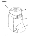
- the inhaler 1 comprises an inhaler body 2 with a mouthpiece that is covered by a removable shroud 3.
- the upper part of the inhaler 1 can be depressed relative to the inhaler body 2, the upper part thus constituting a push button 4 by means of which doses of medicament powders stored in bulk reservoirs within the inhaler body 2 can be dispensed from those reservoirs and inhaled by a user of the inhaler 1.
- the user removes the shroud 3 to expose the mouthpiece, depresses the push button 4 to dispense unit doses of the medicaments, places the mouthpiece to his lips and inhales.
- the doses of medicament that have been dispensed from the bulk reservoirs are entrained in a flow of air through the inhaler 1 and are hence drawn into the user's lungs.
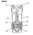
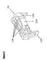
- Figures 2 and 3 show the internal components of the inhaler 1 in greater detail.
- the inhaler 1 comprises a pair of medicament reservoirs 21,22 that are arranged side-by-side.
- the lower end of each reservoir 21,22 is closed by a respective frustoconical metering member 23,24.
- the metering members 23,24 are mounted for rotation about a common axis that is transverse to the longitudinal axis of the reservoirs 21,22.
- Each metering member 23,24 is urged outwardly, into sealing engagement with its associated reservoir 21,22 by a compression spring 25.
- Each metering member is formed with a series of cup-like depressions 26 in its surface, which depressions 26 serve for the volumetric metering of doses of medicament from each reservoir 21,22.
- the metering members 23,24 can be rotated in such a way that a depression 26 in each is brought into a filling position in which it is in registration with the bottom end of the associated reservoir 21,22, so that the depression 26 fills with a quantity of the medicament powder contained within that reservoir 21,22.
- Continued rotation then brings the filled depression into a dispensing position from which the dose of medicament can be entrained in an airflow (indicated by the arrows A, B and C in Figure 2 ) passing over the depression 26, the airflow being caused by the user inhaling through the mouthpiece.
- the airflow in which the medicaments are entrained, passes through an airway 27 that is housed within the mouthpiece.
- the abutting walls of the reservoirs 21,22 are formed with hemi-cylindrical channels that together form a cylindrical channel within which an actuator 28 is slidably mounted.
- the upper ends of reservoirs 21,22 are closed by respective caps 31,32.
- the actuator 28 is acted upon by the push button 4 and serves to index the metering members 23,24 such that a depression 26 in each is moved from the filling to the dispensing position.
- a counter unit 29 is attached to the rear of the reservoirs 21,22 and provides a visual display of the number of actuations of the inhaler 1 at a window (not visible in Figure 1 ) in the rear of the inhaler body 2.
- the inhaler 1 is of known form.
- the inhaler 1 is of the form known as DUOHALER ® , that has been developed by the present applicant, and which is a development of the inhaler sold under the name CLICKHALER ® , a multi-unit-dose reservoir device marketed for the delivery of several different medicaments in Europe and Japan.
- CLICKHALER ® a multi-unit-dose reservoir device marketed for the delivery of several different medicaments in Europe and Japan.
- Such an inhaler allows the independent containment and delivery of two dry powder formulations simultaneously.
- the applicant Whilst the performance of the known inhaler is good, the applicant has sought to develop the device further, and in particular has developed refinements to the device that improve the performance of the device by reducing the ingress of moisture into the reservoirs 21,22. This improved performance, in particular resistance to moisture ingress, may be of importance for the delivery of active ingredients that are especially sensitive to moisture, and may thus extend the utility of the inhaler to the delivery of such medicaments.
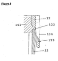
- FIG 4 there is shown the upper part of the medicament reservoir 22. It can be seen that the rim of the reservoir 22 is formed with an upstanding ridge 122.
- the ridge 122 is of generally triangular cross-section (see Figure 7 ).
- FIGS 5 and 6 show the modified form of cap 32 that is used in the inhaler according to the invention.
- the cap 32 comprises a planar base 132 from opposite ends of which depend a pair of clips 133,134 that engage cooperating detents 123 on the external surface of the reservoir 22 (one of the detents 123 being visible in Figure 4 ).
- a wall 135 extends upwardly from the base 132 around the full periphery of the cap 32, and stiffening ribs 136 extend across the cap 32, connecting opposite parts of the wall 135. The effect of the wall 135 and ribs 136 is to increase the stiffness of the cap 32.
- the base 132 of the cap 32 is slightly recessed and has a pair of slots 137,138 located close to the clips 133,134.
- a seal 141 of thermoplastic elastomer is formed in the second stage of a two-shot moulding process, and occupies the recess in the underside of the cap 32 and the slots 137,138.
- the ribs 136 are partially reduced in height, so that the thermoplastic elastomer is able to flow, in the moulding process, through the slots 137,138 and to meet and form a bar extending across the upper side of the cap 32, thereby captivating the seal 141 on the cap 32.
- the recess in the base 132 and the slots 137,138 are omitted, the seal 141 simply being formed on the planar underside of the base 132.
- the seal 141 is not shown in Figure 6 , but can be seen in Figure 8 .
- the cap 32 is engaged with the reservoir 22 as shown in Figure 8 .
- the cap 32 is clipped onto the top of the reservoir 22 such that the clips 133,134 engage the detents 123.
- the upstanding ridge 122 engages and deforms the seal 141, the form of the ridge 122 increasing the contact pressure between the ridge 122 and the seal 141, and thereby reducing the potential for ingress of moisture into the reservoir 22 between the upper edge of the reservoir 121 and the cap 32.
- the cap 31 that is engaged with the reservoir 21 is identical in form to the cap 32, save that it is the mirror image of that cap 32.
Description
- This invention concerns improvements in or relating to inhalers, and in particular to improvements in dry powder inhalers, that is to say devices for the administration of powdered medicament by inhalation, and especially to improvements that reduce the susceptibility of such devices to moisture ingress.
- The administration of medicaments by inhalation is well-known. A wide variety of medicaments are now administered by that route, for the treatment of a range of respiratory disorders.
- Examples of medicaments used for the treatment of respiratory disorders include, among others, anti-allergic agents, eg cromoglycate, ketotifen and nedocromil; anti-inflammatory steroids, eg beclomethasone dipropionate, fluticasone, budesonide, flunisolide, ciclesonide, triamcinolone acetonide and mometasone furoate; bronchodilators, such as ß2-agonists, eg fenoterol, formoterol, pirbuterol, reproterol, salbutamol, salmeterol, indacaterol and terbutaline, non-selective ß-stimulants, eg isoprenaline, and xanthine bronchodilators, eg theophylline, aminophylline and choline theophyllinate; anti-muscarinics, eg trospium chloride and glycopyrrolate (racemate and enantiomers thereof); PDE4 inhibitors, eg cilomilast and roflumilast; calcium channel blockers, eg diltiazem, verapamil, amlodipine, felodipine, lercanidipine and nimodipine; and anticholinergic agents, eg ipratropium bromide, oxitropium bromide and tiotropium.
- The most common form in which such medicaments are formulated for administration by inhalation is as a powder. In the past, many such compositions were formulated as pressurised aerosols, in which the powder medicament was suspended in a liquefied propellant. Due to the adverse environmental effects of the propellants conventionally used, however, there is now increased interest in the use of so-called dry powder inhalers (DPIs). In a DPI, a unit dose of medicament powder, either packaged as such or metered from a bulk reservoir of medicament, is presented to an airway and is then entrained in an airflow passing through the airway. The airflow is most commonly generated by the patient's act of inhalation.
- For the effective treatment of conditions of the respiratory tract it is generally desirable that as high a proportion of the powder as possible should be in the form of particles that are sufficiently fine that they are able to penetrate deep into the airways, and in particular that they should be transported deep into the lung. An important parameter in assessing the effectiveness of powdered medicament intended for inhalation is therefore the fine particle fraction (FPF), which defines the fraction of the emitted dose from an inhaler that has the potential to be deposited in the lung. This fraction is often defined as the proportion of the medicament that is in the form of particles with a diameter of less than 5µm.
- The FPF will depend to some extent on the manner in which the medicament is formulated, but also is strongly dependent on the performance of the device (inhaler) from which the formulation is delivered. It is well known that one problem that can affect the performance of a dry powder inhaler is the ingress of moisture into the device, and in particular into the parts of the inhaler in which medicament is stored prior to delivery to a user of the inhaler. Such problems are particularly acute when the medicament is hygroscopic and/or when the inhaler is stored or used in climatic conditions that give rise to high humidity. Ingress of moisture into dry powder inhalers is therefore generally undesirable as it may lead to agglomeration of the powdered medicament, resulting in reduction of FPF, and potentially to clogging of the device and/or inaccurate dosing of the medicament. Furthermore, some medicaments are susceptible to chemical degradation in the presence of moisture.
- Known inhalers, for example, those disclosed in
DE102006029753A1 ,WO01/43801A US2003136405A1 , do not provide adequate resistance to the ingress of water. There is therefore an ongoing requirement to improve the resistance of inhaler devices to the ingress of moisture. - There have now been devised improvements to dry powder inhalers that result in reduced ingress of moisture into the inhaler, and which may hence improve the performance of the inhaler.
- Thus, according to a first aspect of the invention there is provided a dry powder inhaler comprising at least one medicament reservoir with an opening and a closure member engaged with the reservoir such that there is contact pressure between the reservoir and the closure member, so as to close the opening, characterised in that a surface at the periphery of the opening of the reservoir and a surface of the underside of the closure member are in abutment via a deformable seal member, the deformable seal member being provided on the abutting surface at the periphery of the opening of the reservoir or the abutting surface of the underside of the closure member, or the deformable seal member being interposed between the reservoir and the closure member, and at least one of the abutting surfaces is formed with a projection that increases the contact pressure between said surfaces, thereby improving the seal between the abutting surfaces and reducing the potential for ingress of moisture between said surfaces into the reservoir.
- Preferably, the projection engages the deformable seal member which is provided on the underside of the closure member. Alternatively, the deformable seal member may be interposed between the surface of the reservoir adjacent the opening and the closure member. The seal member may take the form of a ring, of similar shape to the projection, or the seal member may extend across substantially all of the underside of the closure member. Most preferably, the seal member is formed integrally with the closure member, eg in a two-shot moulding process. The material of the seal member is most preferably an elastomer, and more preferably a thermoplastic elastomer. Particularly preferred materials include thermoplastic polyester elastomers, eg that sold under the trade name RITEFLEX® by Ticona UK Ltd of Stafford Court, Telford TF3 3DD, United Kingdom. The projection preferably extends around the full circumference of the opening in the reservoir.
- By "a projection that increases the contact pressure between said surfaces" is meant a projection that reduces the contact area between the surfaces, relative to the contact area that would exist (eg between two substantially planar surfaces) if the projection were absent. It is believed that the reduced contact area leads to an increase in the contact pressure between the closure member and the reservoir.
- The projection preferably has a pointed profile, most preferably a substantially triangular profile.
- The projection is most preferably provided at the periphery of the opening in the reservoir, and engages with the deformable seal member, the deformable seal member being provided on the underside of the closure member. Alternatively, the projection may be provided on the underside of the closure member, and may engage the deformable seal member, the deformable seal member being provided around the periphery of the opening in the reservoir. In further alternatives, the projection may be formed in the deformable seal member.
- The closure member may take the form of a cap that engages with the reservoir in such a manner that the opening in the reservoir is closed off. Most conveniently, the cap engages the reservoir with a clip fitting, the cap and the reservoir being provided with cooperating formations that engage to bring about sealing engagement of the cap with the reservoir. For instance, the cap may be provided with deformable limbs that engage with suitable detents on the reservoir. The contact pressure between the cap and the reservoir may be adjusted by appropriate design of the cooperating formations.
- The applicant has found that the sealing engagement of the closure member with the reservoir may also be improved by measures that increase the rigidity of the closure member, and which thereby reduce any tendency of the closure member to flex.
- Thus, according to some embodiments of the invention the closure member is provided with one or more integral stiffening ribs.
- It is found that by incorporating one or more stiffening ribs into the closure member, the degree of flexure of the closure member during normal use is reduced and this is found to improve the quality of the seal between the closure member and the reservoir. The ingress of moisture into the reservoir is thereby inhibited.
- The components of dry powder inhalers according to the invention may be manufactured by conventional techniques. Most commonly, the components will be formed in plastics materials, by injection moulding processes.
- Dry powder inhalers in which the inventive measures described herein may be particularly appropriate include those that comprise a medicament reservoir and a metering member that closes an opening in the reservoir and which is adapted to transfer a unit dose of medicament from the reservoir to a position from which the dose of medicament can be inhaled by the user of the device. Examples of such devices are those referred to by the names DUOHALER® and CLICKHALER®. The principle of operation of such devices is described in
WO-A-92/00771 WO-A-01/39823 - The inhaler according to the invention may be used to deliver any of a wide range of medicaments. Such medicaments include those that are suitable for the treatment of asthma, COPD and respiratory infections. Examples of such medicaments are given on
page 1 hereof. Other classes of medicaments with which the inhaler may be used include the following: - antivirals, eg zanamivir, ribavirin, flumist, ruprintrivir and pleconaril; antibiotics, eg tobramycin, doripenem, pentamidine, promixin, aztreonam; and antifungals, eg amphotericin B (further examples of medicaments that may potentially be administered using inhalers according to the invention are given in Respiratory Care 2000; 45(7): 836-845);
- immunogens for the prevention or treatment of meningococcal disease, meningitis, septicaemia, meningoccaemia, pneumonia, meningococci of any of groups A, B, C, Y, W135, X and/or Z, anthrax, plague, small pox, tularaemia, meliodosis, Q fever, botulism, typhus, cholera, yellow fever, brucellosis, encephalitis, ricin, salmonella, staphylococcal Enterotoxin B, human immunodeficiency virus, hepatitis B, cytomegalovirus, tuberculosis, and combinations thereof;
- proteinaceous compounds, macromolecules, hormones, mediators, insulin, human growth hormone, leuprolide, alpha-interferon, growth factors, anticoagulants, immunomodulators, cytokines, nucleic acids and combinations thereof;
- antimigraine compounds, particularly triptans. Preferably, the triptan comprises almotriptan, rizatriptan, naratriptan, zolmitriptan, sumatritpan, eletriptan, frovatriptan, and combinations thereof.
- Inhalers according to the invention may also be used to deliver combinations of two or more different medicaments. Specific combinations of medicaments which may be mentioned include combinations of steroids and β2-agonists. Examples of such combinations are beclomethasone and formoterol; beclomethasone and salmeterol; fluticasone and formoterol; fluticasone and salmeterol; budesonide and formoterol; budesonide and salmeterol; flunisolide and formoterol; flunisolide and salmeterol; ciclesonide and salmeterol; ciclesonide and formoterol; mometasone and salmeterol; and mometasone and formoterol. Another preferred combination is indacaterol and glycopyrrolate. Triple combinations include glycopyrrolate, salmeterol and mometasone; glycopyrrolate, indacaterol and mometasone; glycopyrrolate, salmeterol and ciclesonide; glycopyrrolate, indacaterol and ciclesonide. Some or all of the constituents of such combinations can be co-formulated and stored in a single medicament reservoir, but more preferably the individual medicaments that make up the combination are stored in separate reservoirs within the inhaler.
- The invention will now be described in greater detail, by way of illustration only, with reference to the accompanying drawings, in which
-
Figure 1 is a perspective view of a dry powder inhaler according to the invention; -
Figure 2 is a perspective view of the internal components of the inhaler ofFigure 1 ; -
Figure 3 is a side view, partly in section and partly cut away, of a pair of medicament reservoirs and associated dispensing mechanisms that form part of the inhaler ofFigure 1 ; -
Figure 4 is a perspective view of the upper part of a medicament reservoir forming part of the inhaler according to the invention; -
Figure 5 is a perspective view of a medicament reservoir closure cap that forms part of the inhaler according to the invention; -
Figure 6 is a perspective view of the cap ofFigure 5 in an inverted condition; -
Figure 7 is a cross-section on the line VII-VII inFigure 4 ; and -
Figure 8 is a view similar toFigure 7 , but showing the same region of the medicament reservoir when the cap ofFigure 5 is engaged therewith. - Referring first to
Figure 1 , a dry powder inhaler of generally known form is designated 1 and is of the type known by the name DUOHALER®. The principle of action of such an inhaler is described inWO-A-01/39823 WO-A-2005/102429 . - Essentially, the
inhaler 1 comprises aninhaler body 2 with a mouthpiece that is covered by aremovable shroud 3. The upper part of theinhaler 1 can be depressed relative to theinhaler body 2, the upper part thus constituting apush button 4 by means of which doses of medicament powders stored in bulk reservoirs within theinhaler body 2 can be dispensed from those reservoirs and inhaled by a user of theinhaler 1. Thus, in use, the user removes theshroud 3 to expose the mouthpiece, depresses thepush button 4 to dispense unit doses of the medicaments, places the mouthpiece to his lips and inhales. The doses of medicament that have been dispensed from the bulk reservoirs are entrained in a flow of air through theinhaler 1 and are hence drawn into the user's lungs. -
Figures 2 and3 show the internal components of theinhaler 1 in greater detail. Specifically, theinhaler 1 comprises a pair ofmedicament reservoirs reservoir frustoconical metering member metering members reservoirs metering member reservoir compression spring 25. - Each metering member is formed with a series of cup-
like depressions 26 in its surface, which depressions 26 serve for the volumetric metering of doses of medicament from eachreservoir metering members depression 26 in each is brought into a filling position in which it is in registration with the bottom end of the associatedreservoir depression 26 fills with a quantity of the medicament powder contained within thatreservoir Figure 2 ) passing over thedepression 26, the airflow being caused by the user inhaling through the mouthpiece. The airflow, in which the medicaments are entrained, passes through an airway 27 that is housed within the mouthpiece. When thedepression 26 is moved from the filling to the dispensing position, thenext depression 26 is brought into registration with the bottom end of thereservoir - The abutting walls of the
reservoirs actuator 28 is slidably mounted. The upper ends ofreservoirs respective caps - The
actuator 28 is acted upon by thepush button 4 and serves to index themetering members depression 26 in each is moved from the filling to the dispensing position. Acounter unit 29 is attached to the rear of thereservoirs inhaler 1 at a window (not visible inFigure 1 ) in the rear of theinhaler body 2. - The manner in which the
actuator 28 causes themetering members counter unit 29 records the number of actuations, as well as the details of the airway 27, are not pertinent to the present invention and will not be described in any greater detail. - The
inhaler 1, as thus far described, is of known form. Specifically, theinhaler 1 is of the form known as DUOHALER®, that has been developed by the present applicant, and which is a development of the inhaler sold under the name CLICKHALER®, a multi-unit-dose reservoir device marketed for the delivery of several different medicaments in Europe and Japan. Such an inhaler allows the independent containment and delivery of two dry powder formulations simultaneously. - Whilst the performance of the known inhaler is good, the applicant has sought to develop the device further, and in particular has developed refinements to the device that improve the performance of the device by reducing the ingress of moisture into the
reservoirs - In the inhaler of the present invention, modifications have been made, relative to the known form of inhaler, that improve the quality of the seal between the medicament reservoirs and their associated caps.
- Referring now to
Figure 4 , there is shown the upper part of themedicament reservoir 22. It can be seen that the rim of thereservoir 22 is formed with anupstanding ridge 122. Theridge 122 is of generally triangular cross-section (seeFigure 7 ). -
Figures 5 and6 show the modified form ofcap 32 that is used in the inhaler according to the invention. Thecap 32 comprises aplanar base 132 from opposite ends of which depend a pair of clips 133,134 that engage cooperatingdetents 123 on the external surface of the reservoir 22 (one of thedetents 123 being visible inFigure 4 ). Awall 135 extends upwardly from thebase 132 around the full periphery of thecap 32, and stiffeningribs 136 extend across thecap 32, connecting opposite parts of thewall 135. The effect of thewall 135 andribs 136 is to increase the stiffness of thecap 32. As can be seen inFigure 6 , in the embodiment illustrated, thebase 132 of thecap 32 is slightly recessed and has a pair of slots 137,138 located close to the clips 133,134. Aseal 141 of thermoplastic elastomer is formed in the second stage of a two-shot moulding process, and occupies the recess in the underside of thecap 32 and the slots 137,138. In other embodiments, theribs 136 are partially reduced in height, so that the thermoplastic elastomer is able to flow, in the moulding process, through the slots 137,138 and to meet and form a bar extending across the upper side of thecap 32, thereby captivating theseal 141 on thecap 32. In yet further embodiments, the recess in thebase 132 and the slots 137,138 are omitted, theseal 141 simply being formed on the planar underside of thebase 132. Theseal 141 is not shown inFigure 6 , but can be seen inFigure 8 . - The
cap 32 is engaged with thereservoir 22 as shown inFigure 8 . Thecap 32 is clipped onto the top of thereservoir 22 such that the clips 133,134 engage thedetents 123. Theupstanding ridge 122 engages and deforms theseal 141, the form of theridge 122 increasing the contact pressure between theridge 122 and theseal 141, and thereby reducing the potential for ingress of moisture into thereservoir 22 between the upper edge of thereservoir 121 and thecap 32. - The
cap 31 that is engaged with thereservoir 21 is identical in form to thecap 32, save that it is the mirror image of thatcap 32. - It will be appreciated that, in addition to the features of the present invention, further measures may be taken to reduce the extent of moisture ingress into the inhaler. Such measures include, for example, those described in our copending International patent application of even date (Attorney ref: 1620/1675/P/WO), claiming priority from United Kingdom patent application
0800459.0 WO 2009/087407 .
Claims (15)
- A dry powder inhaler (1) comprising at least one medicament reservoir (21,22) with an opening and a closure member (32) engaged with the reservoir (21,22) such that there is contact pressure between the reservoir (21,22) and the closure member (32), so as to close the opening,
characterised in that a surface at the periphery of the opening of the reservoir (21,22) and a surface of the underside of the closure member (32) are in abutment via a deformable seal member (141), the deformable seal member (141) being provided on the abutting surface at the periphery of the opening of the reservoir (21,22) or the abutting surface of the underside of the closure member, or the deformable seal member (141) being interposed between the reservoir (21,22) and the closure member (32), and at least one of the abutting surfaces is formed with a projection (122) that increases the contact pressure between said surfaces, thereby improving the seal (141) between the abutting surfaces and reducing the potential for ingress of moisture between said surfaces into the reservoir (21,22). - A dry powder inhaler (1) as claimed in Claim 1, wherein the projection (122) engages the deformable seal member (141) which is provided on the underside of the closure member (32).
- A dry powder inhaler (1) as claimed in Claim 1, wherein the deformable seal member (141) is interposed between the surface of the reservoir (21,22) adjacent the opening and the closure member (32).
- A dry powder inhaler (1) as claimed in Claim 3, wherein the seal member (141) extends across substantially all of the underside of the closure member (32).
- A dry powder inhaler (1) as claimed in Claim 4, wherein the seal member (141) is formed integrally with the closure member (32) in a two-shot moulding process.
- A dry powder inhaler (1) as claimed in any one of Claims 3 to 5, wherein the material of the seal member (141) is an elastomer.
- A dry powder inhaler (1) as claimed in Claim 6, wherein the elastomer is a thermoplastic polyester elastomer.
- A dry powder inhaler (1) as claimed in any preceding claim, wherein the projection (122) extends around the full circumference of the opening in the reservoir (21,22).
- A dry powder inhaler (1) as claimed in any preceding claim, wherein the projection (122) has a pointed profile.
- A dry powder inhaler (1) as claimed in Claim 9, wherein the projection (122) has a substantially triangular profile.
- A dry powder inhaler (1) as claimed in any preceding claim, wherein the projection (122) is provided at the periphery of the opening in the reservoir (21,22), and engages with the deformable seal member (141), the deformable seal member (141) being provided on the underside of the closure member (32).
- A dry powder inhaler (1) as claimed in Claim 11, wherein the underside of the closure member (32) is slightly recessed and has a pair of slots (137,138), and the deformable seal member (141) occupies the recess in the underside of the closure member (32) and the pair of slots (137,138).
- A dry powder inhaler (1) as claimed in any of Claim 1, and Claims 3 to 10, wherein the projection (122) is provided on the underside of the closure member (32), and engages the deformable seal member (141), the deformable seal member (141) being provided around the periphery of the opening in the reservoir (21,22).
- A dry powder inhaler (1) as claimed in any of Claim 1, and Claims 3 to 10, wherein the projection (122) is formed in the deformable seal member (141).
- A dry powder inhaler (1) as claimed in any preceding claim, wherein the closure member (32) is a cap that engages with the reservoir (21,22) with a clip fitting, the cap and the reservoir (21,22) being provided with cooperating formations (123; 133) that engage to bring about sealing engagement of the cap with the reservoir (21,22).
Priority Applications (1)
| Application Number | Priority Date | Filing Date | Title |
|---|---|---|---|
| EP15179189.4A EP3020436B1 (en) | 2008-01-11 | 2009-01-12 | Improvements in or relating to inhalers |
Applications Claiming Priority (2)
| Application Number | Priority Date | Filing Date | Title |
|---|---|---|---|
| GBGB0800457.4A GB0800457D0 (en) | 2008-01-11 | 2008-01-11 | Improvements in or relating to inhalers |
| PCT/GB2009/000074 WO2009087404A1 (en) | 2008-01-11 | 2009-01-12 | Improvements in or relating to inhalers |
Related Child Applications (2)
| Application Number | Title | Priority Date | Filing Date |
|---|---|---|---|
| EP15179189.4A Division EP3020436B1 (en) | 2008-01-11 | 2009-01-12 | Improvements in or relating to inhalers |
| EP15179189.4A Division-Into EP3020436B1 (en) | 2008-01-11 | 2009-01-12 | Improvements in or relating to inhalers |
Publications (2)
| Publication Number | Publication Date |
|---|---|
| EP2240227A1 EP2240227A1 (en) | 2010-10-20 |
| EP2240227B1 true EP2240227B1 (en) | 2015-10-07 |
Family
ID=39144755
Family Applications (2)
| Application Number | Title | Priority Date | Filing Date |
|---|---|---|---|
| EP15179189.4A Active EP3020436B1 (en) | 2008-01-11 | 2009-01-12 | Improvements in or relating to inhalers |
| EP09701343.7A Not-in-force EP2240227B1 (en) | 2008-01-11 | 2009-01-12 | Improvements in or relating to inhalers |
Family Applications Before (1)
| Application Number | Title | Priority Date | Filing Date |
|---|---|---|---|
| EP15179189.4A Active EP3020436B1 (en) | 2008-01-11 | 2009-01-12 | Improvements in or relating to inhalers |
Country Status (5)
| Country | Link |
|---|---|
| US (1) | US8800554B2 (en) |
| EP (2) | EP3020436B1 (en) |
| GB (1) | GB0800457D0 (en) |
| HK (1) | HK1150156A1 (en) |
| WO (1) | WO2009087404A1 (en) |
Families Citing this family (8)
| Publication number | Priority date | Publication date | Assignee | Title |
|---|---|---|---|---|
| ES2394589T3 (en) | 2007-12-14 | 2013-02-04 | Aerodesigns, Inc | Supply of food products transformable in aerosol |
| GB0800459D0 (en) * | 2008-01-11 | 2008-02-20 | Innovata Biomed Ltd | Improvements in or relating to inhalers |
| GB0912373D0 (en) | 2009-07-16 | 2009-08-26 | Innovata Biomed Ltd | Improvements in or relating to dry powder inhalers |
| WO2012072542A1 (en) * | 2010-11-29 | 2012-06-07 | Sanofi-Aventis Deutschland Gmbh | Medicated module for an inhaler |
| GB2498746A (en) | 2012-01-26 | 2013-07-31 | Innovata Biomed Ltd | Inhaler which locks when empty |
| USD781412S1 (en) * | 2015-04-09 | 2017-03-14 | Celon Pharma S.A. | Inhaler |
| ES2964101T3 (en) * | 2018-07-16 | 2024-04-04 | Invox Belgium Nv | Improved inhalation device |
| USD960349S1 (en) * | 2019-02-04 | 2022-08-09 | Orion Corporation | Inhaler |
Family Cites Families (16)
| Publication number | Priority date | Publication date | Assignee | Title |
|---|---|---|---|---|
| GB8909891D0 (en) | 1989-04-28 | 1989-06-14 | Riker Laboratories Inc | Device |
| GB9015522D0 (en) | 1990-07-13 | 1990-08-29 | Braithwaite Philip W | Inhaler |
| US5314084A (en) * | 1992-08-21 | 1994-05-24 | The West Company, Incorporated | Two piece all plastic seal |
| WO1996008284A2 (en) * | 1994-09-16 | 1996-03-21 | Laboratoire Glaxo Wellcome | Inhalation device |
| GB9700226D0 (en) * | 1997-01-08 | 1997-02-26 | Glaxo Group Ltd | Inhalation device |
| IT238038Y1 (en) * | 1997-11-12 | 2000-09-29 | Miat Spa | MULTI-DOSE DISPENSER OF A SUBSTANCE IN POWDER OR IN GRAINS, OF THE INCUI TYPE |
| GB9905538D0 (en) * | 1999-03-10 | 1999-05-05 | Glaxo Group Ltd | A device |
| FI108518B (en) * | 1999-04-23 | 2002-02-15 | Orion Yhtymae Oyj | Powder inhaler for combination medicine |
| GB9928265D0 (en) * | 1999-12-01 | 2000-01-26 | Innovata Biomed Ltd | Inhaler |
| DE19961300A1 (en) * | 1999-12-18 | 2001-06-21 | Asta Medica Ag | Storage system for medicinal products in powder form and inhaler equipped with them |
| TWI224512B (en) * | 2000-06-23 | 2004-12-01 | Norton Healthcare Ltd | Reservoir pressure system for medicament inhaler |
| US7258118B2 (en) | 2002-01-24 | 2007-08-21 | Sofotec Gmbh & Co, Kg | Pharmaceutical powder cartridge, and inhaler equipped with same |
| US6874647B2 (en) * | 2002-08-12 | 2005-04-05 | Owens-Illinois Closure Inc. | Plastic closure, closure and container package, and method of manufacture |
| DE10332748A1 (en) | 2003-07-17 | 2005-02-17 | Saurer Gmbh & Co. Kg | Ring spinning spindle |
| WO2005102429A1 (en) * | 2004-04-21 | 2005-11-03 | Innovata Biomed Limited | Inhaler |
| DE102006029753A1 (en) | 2006-03-10 | 2007-09-13 | Alfred Von Schuckmann | Inhaler for powdered substances |
-
2008
- 2008-01-11 GB GBGB0800457.4A patent/GB0800457D0/en not_active Ceased
-
2009
- 2009-01-12 EP EP15179189.4A patent/EP3020436B1/en active Active
- 2009-01-12 EP EP09701343.7A patent/EP2240227B1/en not_active Not-in-force
- 2009-01-12 US US12/812,582 patent/US8800554B2/en not_active Expired - Fee Related
- 2009-01-12 WO PCT/GB2009/000074 patent/WO2009087404A1/en active Application Filing
-
2011
- 2011-04-15 HK HK11103822.5A patent/HK1150156A1/en unknown
Also Published As
| Publication number | Publication date |
|---|---|
| GB0800457D0 (en) | 2008-02-20 |
| EP3020436B1 (en) | 2017-10-18 |
| EP2240227A1 (en) | 2010-10-20 |
| US8800554B2 (en) | 2014-08-12 |
| WO2009087404A1 (en) | 2009-07-16 |
| US20100288277A1 (en) | 2010-11-18 |
| EP3020436A1 (en) | 2016-05-18 |
| HK1150156A1 (en) | 2011-11-04 |
Similar Documents
| Publication | Publication Date | Title |
|---|---|---|
| EP2240227B1 (en) | Improvements in or relating to inhalers | |
| US8132565B2 (en) | Inhaler for powdery substances | |
| CA2572790C (en) | Inhaler for the administration of powdered pharmaceuticals, and a powder cartridge system for use with this inhaler | |
| RU2201768C2 (en) | Inhalation device | |
| US7954492B2 (en) | Pharmaceutical powder cartridge, and inhaler equipped with same | |
| AU2002350512B2 (en) | Medicament dispenser | |
| JP5841429B2 (en) | Inhaler with audible indicator means | |
| TWI547293B (en) | Improvements relating to medicament delivery devices | |
| WO2000074754A2 (en) | Delivery system | |
| EP2817049B1 (en) | Improvements relating to medicament delivery devices | |
| EP2237825B1 (en) | Improvements in or relating to inhalers | |
| WO2014012930A2 (en) | Metering element for an inhalation device and inhalation device comprising a metering element |
Legal Events
| Date | Code | Title | Description |
|---|---|---|---|
| PUAI | Public reference made under article 153(3) epc to a published international application that has entered the european phase |
Free format text: ORIGINAL CODE: 0009012 |
|
| 17P | Request for examination filed |
Effective date: 20100708 |
|
| AK | Designated contracting states |
Kind code of ref document: A1 Designated state(s): AT BE BG CH CY CZ DE DK EE ES FI FR GB GR HR HU IE IS IT LI LT LU LV MC MK MT NL NO PL PT RO SE SI SK TR |
|
| AX | Request for extension of the european patent |
Extension state: AL BA RS |
|
| DAX | Request for extension of the european patent (deleted) | ||
| REG | Reference to a national code |
Ref country code: HK Ref legal event code: DE Ref document number: 1150156 Country of ref document: HK |
|
| 17Q | First examination report despatched |
Effective date: 20111209 |
|
| GRAP | Despatch of communication of intention to grant a patent |
Free format text: ORIGINAL CODE: EPIDOSNIGR1 |
|
| INTG | Intention to grant announced |
Effective date: 20131028 |
|
| RAP1 | Party data changed (applicant data changed or rights of an application transferred) |
Owner name: INNOVATA BIOMED LIMITED |
|
| RIN1 | Information on inventor provided before grant (corrected) |
Inventor name: GORDON, JAMES Inventor name: BRIANT, JOHN, PHILIP Inventor name: RUDGE, ROBERT, ANDREW, Inventor name: PARKES, PHILIP, CARL Inventor name: MORRIS, ANDREW, PAUL Inventor name: BRADSHAW, DOUGLAS, ROBERT, SAUNDERS Inventor name: STREETER, ADRIAN, JOHN, |
|
| RIN1 | Information on inventor provided before grant (corrected) |
Inventor name: BRADSHAW, DOUGLAS, ROBERT, SAUNDERS Inventor name: STREETER, ADRIAN, JOHN, Inventor name: GORDON, JAMES Inventor name: RUDGE, ROBERT, ANDREW, Inventor name: BRIANT, JOHN, PHILIP Inventor name: PARKES, PHILIP, CARL Inventor name: MORRIS, ANDREW, PAUL |
|
| GRAP | Despatch of communication of intention to grant a patent |
Free format text: ORIGINAL CODE: EPIDOSNIGR1 |
|
| INTG | Intention to grant announced |
Effective date: 20141210 |
|
| GRAP | Despatch of communication of intention to grant a patent |
Free format text: ORIGINAL CODE: EPIDOSNIGR1 |
|
| INTG | Intention to grant announced |
Effective date: 20150506 |
|
| GRAS | Grant fee paid |
Free format text: ORIGINAL CODE: EPIDOSNIGR3 |
|
| GRAA | (expected) grant |
Free format text: ORIGINAL CODE: 0009210 |
|
| AK | Designated contracting states |
Kind code of ref document: B1 Designated state(s): AT BE BG CH CY CZ DE DK EE ES FI FR GB GR HR HU IE IS IT LI LT LU LV MC MK MT NL NO PL PT RO SE SI SK TR |
|
| REG | Reference to a national code |
Ref country code: GB Ref legal event code: FG4D |
|
| REG | Reference to a national code |
Ref country code: AT Ref legal event code: REF Ref document number: 753348 Country of ref document: AT Kind code of ref document: T Effective date: 20151015 Ref country code: CH Ref legal event code: EP |
|
| REG | Reference to a national code |
Ref country code: IE Ref legal event code: FG4D |
|
| REG | Reference to a national code |
Ref country code: DE Ref legal event code: R096 Ref document number: 602009034012 Country of ref document: DE |
|
| REG | Reference to a national code |
Ref country code: FR Ref legal event code: PLFP Year of fee payment: 8 |
|
| REG | Reference to a national code |
Ref country code: NL Ref legal event code: MP Effective date: 20151007 |
|
| REG | Reference to a national code |
Ref country code: AT Ref legal event code: MK05 Ref document number: 753348 Country of ref document: AT Kind code of ref document: T Effective date: 20151007 |
|
| REG | Reference to a national code |
Ref country code: LT Ref legal event code: MG4D |
|
| REG | Reference to a national code |
Ref country code: HK Ref legal event code: GR Ref document number: 1150156 Country of ref document: HK |
|
| PG25 | Lapsed in a contracting state [announced via postgrant information from national office to epo] |
Ref country code: NO Free format text: LAPSE BECAUSE OF FAILURE TO SUBMIT A TRANSLATION OF THE DESCRIPTION OR TO PAY THE FEE WITHIN THE PRESCRIBED TIME-LIMIT Effective date: 20160107 Ref country code: IT Free format text: LAPSE BECAUSE OF FAILURE TO SUBMIT A TRANSLATION OF THE DESCRIPTION OR TO PAY THE FEE WITHIN THE PRESCRIBED TIME-LIMIT Effective date: 20151007 Ref country code: LT Free format text: LAPSE BECAUSE OF FAILURE TO SUBMIT A TRANSLATION OF THE DESCRIPTION OR TO PAY THE FEE WITHIN THE PRESCRIBED TIME-LIMIT Effective date: 20151007 Ref country code: ES Free format text: LAPSE BECAUSE OF FAILURE TO SUBMIT A TRANSLATION OF THE DESCRIPTION OR TO PAY THE FEE WITHIN THE PRESCRIBED TIME-LIMIT Effective date: 20151007 Ref country code: IS Free format text: LAPSE BECAUSE OF FAILURE TO SUBMIT A TRANSLATION OF THE DESCRIPTION OR TO PAY THE FEE WITHIN THE PRESCRIBED TIME-LIMIT Effective date: 20160207 Ref country code: HR Free format text: LAPSE BECAUSE OF FAILURE TO SUBMIT A TRANSLATION OF THE DESCRIPTION OR TO PAY THE FEE WITHIN THE PRESCRIBED TIME-LIMIT Effective date: 20151007 Ref country code: NL Free format text: LAPSE BECAUSE OF FAILURE TO SUBMIT A TRANSLATION OF THE DESCRIPTION OR TO PAY THE FEE WITHIN THE PRESCRIBED TIME-LIMIT Effective date: 20151007 |
|
| PG25 | Lapsed in a contracting state [announced via postgrant information from national office to epo] |
Ref country code: PT Free format text: LAPSE BECAUSE OF FAILURE TO SUBMIT A TRANSLATION OF THE DESCRIPTION OR TO PAY THE FEE WITHIN THE PRESCRIBED TIME-LIMIT Effective date: 20160208 Ref country code: LV Free format text: LAPSE BECAUSE OF FAILURE TO SUBMIT A TRANSLATION OF THE DESCRIPTION OR TO PAY THE FEE WITHIN THE PRESCRIBED TIME-LIMIT Effective date: 20151007 Ref country code: BE Free format text: LAPSE BECAUSE OF NON-PAYMENT OF DUE FEES Effective date: 20160131 Ref country code: AT Free format text: LAPSE BECAUSE OF FAILURE TO SUBMIT A TRANSLATION OF THE DESCRIPTION OR TO PAY THE FEE WITHIN THE PRESCRIBED TIME-LIMIT Effective date: 20151007 Ref country code: GR Free format text: LAPSE BECAUSE OF FAILURE TO SUBMIT A TRANSLATION OF THE DESCRIPTION OR TO PAY THE FEE WITHIN THE PRESCRIBED TIME-LIMIT Effective date: 20160108 Ref country code: FI Free format text: LAPSE BECAUSE OF FAILURE TO SUBMIT A TRANSLATION OF THE DESCRIPTION OR TO PAY THE FEE WITHIN THE PRESCRIBED TIME-LIMIT Effective date: 20151007 Ref country code: SE Free format text: LAPSE BECAUSE OF FAILURE TO SUBMIT A TRANSLATION OF THE DESCRIPTION OR TO PAY THE FEE WITHIN THE PRESCRIBED TIME-LIMIT Effective date: 20151007 Ref country code: PL Free format text: LAPSE BECAUSE OF FAILURE TO SUBMIT A TRANSLATION OF THE DESCRIPTION OR TO PAY THE FEE WITHIN THE PRESCRIBED TIME-LIMIT Effective date: 20151007 |
|
| REG | Reference to a national code |
Ref country code: DE Ref legal event code: R097 Ref document number: 602009034012 Country of ref document: DE |
|
| PG25 | Lapsed in a contracting state [announced via postgrant information from national office to epo] |
Ref country code: CZ Free format text: LAPSE BECAUSE OF FAILURE TO SUBMIT A TRANSLATION OF THE DESCRIPTION OR TO PAY THE FEE WITHIN THE PRESCRIBED TIME-LIMIT Effective date: 20151007 |
|
| PLBE | No opposition filed within time limit |
Free format text: ORIGINAL CODE: 0009261 |
|
| STAA | Information on the status of an ep patent application or granted ep patent |
Free format text: STATUS: NO OPPOSITION FILED WITHIN TIME LIMIT |
|
| PG25 | Lapsed in a contracting state [announced via postgrant information from national office to epo] |
Ref country code: RO Free format text: LAPSE BECAUSE OF FAILURE TO SUBMIT A TRANSLATION OF THE DESCRIPTION OR TO PAY THE FEE WITHIN THE PRESCRIBED TIME-LIMIT Effective date: 20151007 Ref country code: LU Free format text: LAPSE BECAUSE OF FAILURE TO SUBMIT A TRANSLATION OF THE DESCRIPTION OR TO PAY THE FEE WITHIN THE PRESCRIBED TIME-LIMIT Effective date: 20160112 Ref country code: EE Free format text: LAPSE BECAUSE OF FAILURE TO SUBMIT A TRANSLATION OF THE DESCRIPTION OR TO PAY THE FEE WITHIN THE PRESCRIBED TIME-LIMIT Effective date: 20151007 Ref country code: SK Free format text: LAPSE BECAUSE OF FAILURE TO SUBMIT A TRANSLATION OF THE DESCRIPTION OR TO PAY THE FEE WITHIN THE PRESCRIBED TIME-LIMIT Effective date: 20151007 Ref country code: DK Free format text: LAPSE BECAUSE OF FAILURE TO SUBMIT A TRANSLATION OF THE DESCRIPTION OR TO PAY THE FEE WITHIN THE PRESCRIBED TIME-LIMIT Effective date: 20151007 |
|
| REG | Reference to a national code |
Ref country code: CH Ref legal event code: PL |
|
| 26N | No opposition filed |
Effective date: 20160708 |
|
| PG25 | Lapsed in a contracting state [announced via postgrant information from national office to epo] |
Ref country code: MC Free format text: LAPSE BECAUSE OF FAILURE TO SUBMIT A TRANSLATION OF THE DESCRIPTION OR TO PAY THE FEE WITHIN THE PRESCRIBED TIME-LIMIT Effective date: 20151007 |
|
| PG25 | Lapsed in a contracting state [announced via postgrant information from national office to epo] |
Ref country code: LI Free format text: LAPSE BECAUSE OF NON-PAYMENT OF DUE FEES Effective date: 20160131 Ref country code: CH Free format text: LAPSE BECAUSE OF NON-PAYMENT OF DUE FEES Effective date: 20160131 |
|
| REG | Reference to a national code |
Ref country code: IE Ref legal event code: MM4A |
|
| PG25 | Lapsed in a contracting state [announced via postgrant information from national office to epo] |
Ref country code: SI Free format text: LAPSE BECAUSE OF FAILURE TO SUBMIT A TRANSLATION OF THE DESCRIPTION OR TO PAY THE FEE WITHIN THE PRESCRIBED TIME-LIMIT Effective date: 20151007 |
|
| PG25 | Lapsed in a contracting state [announced via postgrant information from national office to epo] |
Ref country code: BE Free format text: LAPSE BECAUSE OF FAILURE TO SUBMIT A TRANSLATION OF THE DESCRIPTION OR TO PAY THE FEE WITHIN THE PRESCRIBED TIME-LIMIT Effective date: 20151007 |
|
| REG | Reference to a national code |
Ref country code: FR Ref legal event code: PLFP Year of fee payment: 9 |
|
| PG25 | Lapsed in a contracting state [announced via postgrant information from national office to epo] |
Ref country code: IE Free format text: LAPSE BECAUSE OF NON-PAYMENT OF DUE FEES Effective date: 20160112 |
|
| PG25 | Lapsed in a contracting state [announced via postgrant information from national office to epo] |
Ref country code: MT Free format text: LAPSE BECAUSE OF FAILURE TO SUBMIT A TRANSLATION OF THE DESCRIPTION OR TO PAY THE FEE WITHIN THE PRESCRIBED TIME-LIMIT Effective date: 20151007 |
|
| REG | Reference to a national code |
Ref country code: FR Ref legal event code: PLFP Year of fee payment: 10 |
|
| PG25 | Lapsed in a contracting state [announced via postgrant information from national office to epo] |
Ref country code: HU Free format text: LAPSE BECAUSE OF FAILURE TO SUBMIT A TRANSLATION OF THE DESCRIPTION OR TO PAY THE FEE WITHIN THE PRESCRIBED TIME-LIMIT; INVALID AB INITIO Effective date: 20090112 Ref country code: CY Free format text: LAPSE BECAUSE OF FAILURE TO SUBMIT A TRANSLATION OF THE DESCRIPTION OR TO PAY THE FEE WITHIN THE PRESCRIBED TIME-LIMIT Effective date: 20151007 |
|
| PG25 | Lapsed in a contracting state [announced via postgrant information from national office to epo] |
Ref country code: MT Free format text: LAPSE BECAUSE OF FAILURE TO SUBMIT A TRANSLATION OF THE DESCRIPTION OR TO PAY THE FEE WITHIN THE PRESCRIBED TIME-LIMIT Effective date: 20160131 Ref country code: TR Free format text: LAPSE BECAUSE OF FAILURE TO SUBMIT A TRANSLATION OF THE DESCRIPTION OR TO PAY THE FEE WITHIN THE PRESCRIBED TIME-LIMIT Effective date: 20151007 Ref country code: MK Free format text: LAPSE BECAUSE OF FAILURE TO SUBMIT A TRANSLATION OF THE DESCRIPTION OR TO PAY THE FEE WITHIN THE PRESCRIBED TIME-LIMIT Effective date: 20151007 |
|
| PG25 | Lapsed in a contracting state [announced via postgrant information from national office to epo] |
Ref country code: BG Free format text: LAPSE BECAUSE OF FAILURE TO SUBMIT A TRANSLATION OF THE DESCRIPTION OR TO PAY THE FEE WITHIN THE PRESCRIBED TIME-LIMIT Effective date: 20151007 |
|
| PGFP | Annual fee paid to national office [announced via postgrant information from national office to epo] |
Ref country code: FR Payment date: 20210125 Year of fee payment: 13 |
|
| PGFP | Annual fee paid to national office [announced via postgrant information from national office to epo] |
Ref country code: DE Payment date: 20210127 Year of fee payment: 13 Ref country code: GB Payment date: 20210128 Year of fee payment: 13 |
|
| REG | Reference to a national code |
Ref country code: DE Ref legal event code: R119 Ref document number: 602009034012 Country of ref document: DE |
|
| GBPC | Gb: european patent ceased through non-payment of renewal fee |
Effective date: 20220112 |
|
| PG25 | Lapsed in a contracting state [announced via postgrant information from national office to epo] |
Ref country code: GB Free format text: LAPSE BECAUSE OF NON-PAYMENT OF DUE FEES Effective date: 20220112 Ref country code: DE Free format text: LAPSE BECAUSE OF NON-PAYMENT OF DUE FEES Effective date: 20220802 |
|
| PG25 | Lapsed in a contracting state [announced via postgrant information from national office to epo] |
Ref country code: FR Free format text: LAPSE BECAUSE OF NON-PAYMENT OF DUE FEES Effective date: 20220131 |