EP2240118B1 - Mundpflegegerät mit Multifunktionsschalter - Google Patents
Mundpflegegerät mit Multifunktionsschalter Download PDFInfo
- Publication number
- EP2240118B1 EP2240118B1 EP08862383A EP08862383A EP2240118B1 EP 2240118 B1 EP2240118 B1 EP 2240118B1 EP 08862383 A EP08862383 A EP 08862383A EP 08862383 A EP08862383 A EP 08862383A EP 2240118 B1 EP2240118 B1 EP 2240118B1
- Authority
- EP
- European Patent Office
- Prior art keywords
- oral care
- care appliance
- chamber
- hollow chamber
- assembly
- Prior art date
- Legal status (The legal status is an assumption and is not a legal conclusion. Google has not performed a legal analysis and makes no representation as to the accuracy of the status listed.)
- Not-in-force
Links
- 239000007788 liquid Substances 0.000 claims description 29
- 239000012530 fluid Substances 0.000 abstract 2
- 238000004140 cleaning Methods 0.000 description 5
- 238000007789 sealing Methods 0.000 description 2
- 230000004048 modification Effects 0.000 description 1
- 238000012986 modification Methods 0.000 description 1
- 230000002093 peripheral effect Effects 0.000 description 1
- 238000006467 substitution reaction Methods 0.000 description 1
Images
Classifications
-
- A—HUMAN NECESSITIES
- A61—MEDICAL OR VETERINARY SCIENCE; HYGIENE
- A61C—DENTISTRY; APPARATUS OR METHODS FOR ORAL OR DENTAL HYGIENE
- A61C17/00—Devices for cleaning, polishing, rinsing or drying teeth, teeth cavities or prostheses; Saliva removers; Dental appliances for receiving spittle
- A61C17/02—Rinsing or air-blowing devices, e.g. using fluid jets or comprising liquid medication
- A61C17/0217—Rinsing or air-blowing devices, e.g. using fluid jets or comprising liquid medication having means for manually controlling the supply of two or more fluids, e.g. water and air
-
- A—HUMAN NECESSITIES
- A61—MEDICAL OR VETERINARY SCIENCE; HYGIENE
- A61C—DENTISTRY; APPARATUS OR METHODS FOR ORAL OR DENTAL HYGIENE
- A61C17/00—Devices for cleaning, polishing, rinsing or drying teeth, teeth cavities or prostheses; Saliva removers; Dental appliances for receiving spittle
- A61C17/02—Rinsing or air-blowing devices, e.g. using fluid jets or comprising liquid medication
- A61C17/0202—Hand-pieces
Definitions
- This invention relates generally to an oral care appliance which uses pressurized gas and liquid to accomplish teeth cleaning, and more specifically concerns a switch assembly which actuates multiple functions of the appliance.
- an oral care appliance which includes a source of compressed gas, a source of liquid, a mixing chamber for mixing the gas and the liquid to produce a stream of liquid droplets directed out through a nozzle assembly, and a multi-function switch comprising: a switch housing having a hollow chamber therein; an actuation assembly which includes a stem portion having an O-ring assembly around the periphery thereof; an inlet channel connecting the source of compressed gas to the hollow chamber in the housing; an outlet channel connecting the hollow chamber to the mixing chamber; wherein the O-rings are positioned on the stem portion relative to the inlet channel and the outlet channel such that in a first position of the actuation assembly, one O-ring seals the inlet channel at the hollow chamber and, as the actuation assembly is actuated, the stem portion moves such that the outlet channel at the hollow chamber is or continues to be sealed by another O-ring, and the inlet channel is uncovered, allowing into the hollow chamber an amount of gas, while at that point or thereafter a pump is activated to move liquid
- WO 98/17198 discloses an oral care appliance comprising a source of compressed gas, a source of liquid, a switch housing, an actuation assembly, and an inlet channel as mentioned. Furthermore, the oral care appliance comprises a nozzle at the end of which the gas and the liquid are mixed to produce a stream of liquid droplets, and an outlet channel connecting the hollow chamber of the switch housing to the nozzle.
- the actuation assembly comprises two O-rings which are positioned on the stem portion, wherein one of the O-rings has a function in closing an end of the actuation assembly when the stem portion is in a default position, and wherein another of the O-rings has a sealing function at another side of the actuation assembly.
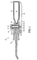
- FIG. 1 shows an oral care appliance which is particularly adapted for cleaning interproximal areas of the teeth, but which can also clean the exposed surfaces of the teeth as well.
- the appliance shown generally at 10, includes a housing 12, with an end or base cap/plug 14 at a rear end and a nozzle assembly 16 extending from the other end.
- the appliance 10 in general operation uses a source of compressed gas, such as a CO 2 cartridge 18, and a source of liquid, stored in a reservoir 20, to produce a stream of liquid droplets directed through nozzle 16 for use in oral cleaning, including cleaning the interproximal areas of the teeth.
- a source of compressed gas such as a CO 2 cartridge 18, and a source of liquid, stored in a reservoir 20, to produce a stream of liquid droplets directed through nozzle 16 for use in oral cleaning, including cleaning the interproximal areas of the teeth.
- Such an appliance is in general well-known.
- a multi-function switch 24 which function in some respects like a valve, is used to control a metered, i.e . fixed, amount of pressurized gas from cartridge 18 and liquid from reservoir 20 into a mixing chamber 26, where the liquid is mixed with the pressurized gas to produce the stream of liquid droplets, which are then directed through nozzle assembly 16 to the teeth.
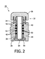
- Switch assembly 24 includes a housing 28 having a hollow interior chamber 30 therein. Housing 28 is configured to extend laterally across the longitudinal dimension of the appliance, but other arrangements and configurations for the switch 24 are possible.
- Button assembly 32 which is biased by a spring 34 in a first position.
- Button assembly 32 includes a button 36 which is generally round and otherwise configured to conveniently accommodate a finger of the user. In the first position of the button assembly, button 36 is positioned slightly away from the housing.
- Button assembly 32 also includes a stem 40 which fits into chamber 30 of housing 28 in an air-tight relationship. Operation, i.e. pushing, of button 36 in a direction toward housing 28, moves stem portion 40 within housing 28.
- Mounted in the peripheral surface of stem are several O-rings 42-42 ( Figure 2 ) at spaced intervals along the stem. In the embodiment shown, there are four separate O-rings 42-42. The O-rings 42 extend from the surface of stem 40 to the interior wall 44 of chamber 30.
- Hollow needle 48 mates with an inlet channel 50 which extends through the wall 49 of housing 28 of the switch assembly to chamber 30.
- channel 50 is positioned at an angle through wall 49 of housing 28.
- Outlet channel 52 Extending through the wall 49 of housing 28 on the opposite side of chamber 30 is an outlet channel 52.
- Outlet channel 52 is also angled and opens into chamber 30 at a different longitudinal point than inlet channel 50 along the length of chamber 30.
- the inlet and outlet channels are circular in cross-section, approximately 2 millimeters in diameter, although this may be varied.
- the forward end 56 of liquid reservoir 20 is connected through a liquid channel 58 to mixing chamber 26.
- Reservoir 20 includes a manual pump 60, by which liquid from the reservoir is moved through channel 58 into mixing chamber 26.
- Pump 60 is positioned so that an actuating portion 62 thereof extends into chamber 30 a small distance for contact with a distal end 64 of stem 40 when button assembly 32 is operated.
- inlet channel 50 at the entrance to chamber 30 is closed off by one O-ring 42.
- the O-rings 42 are mounted on stem 40 such that when button 36 is pushed, moving to its second, operated position, another of the O-rings 42 first seals the exit to outlet channel 52. This is accomplished while the inlet channel 50 into chamber 30 is sealed. Alternatively, outlet channel could have already been sealed and remains sealed while button 36 is pushed. Subsequent to outlet channel 52 being sealed, inlet channel 50 is opened, by virtue of the O-ring at that channel moving away from that channel opening as stem 40 moves within the chamber due to the pushing of the button 36. At this point, a specific, metered volume of gas enters into the chamber 30 through angled inlet channel 50. The defined volume of the chamber results in a precise amount of gas entering the chamber before the pressure is equalized between the chamber 30 and the cartridge.
- button assembly 32 also results in distal end 64 of stem 40 actuating pump 60, resulting in a selected amount of liquid being moved from reservoir 20 directed through channel 58 into mixing chamber 26.
- buttons 36 are then released, which allows spring 34 to return the button assembly 32 to its first position, which results first in one O-ring 42 sealing the inlet channel 50 again and then, subsequent thereto, one O-ring 42 which previously sealed outlet channel 52 moving away from the outlet channel, resulting in the angled outlet channel being opened.
- an outlet slot in the outlet of the chamber is provided to receive the O-ring.
- the O-ring is forced by the high pressure gas present in the chamber into the slot, opening the path for the gas to flow into the outlet instantaneously, such that the opening of the outlet is independent of the action of the user after gas has entered the chamber.
- nozzle assembly 16 This results in the gas present in chamber 30 expanding out through channel 52 into mixing chamber 26, where the mixing of the pressurized gas from the chamber 30 and the liquid from reservoir 20 results in a stream of liquid droplets which proceed from the mixing chamber 26 into the proximal end 66 of nozzle assembly 16.
- the liquid droplets continue through the nozzle assembly 16 to the outlet there from, for use in cleaning of teeth.
- the nozzle assembly 16 could also include a guidance tip which is designed to fit in the interproximal areas of the teeth.
- switch 10 could be configured to accomplish other functions as it is moved from its first (rest) to its second (operative) position and vice versa.
- electrical contacts could be positioned within chamber 30 volume so that movement of the button assembly could connect the contacts to operate another switch or activate a circuit to accomplish other functions, such as energizing an LED or status indicator or other similar function.
- a switch assembly which, in operation, will produce a sequence of specific operations of the appliance.
- a single switch structure can thus accomplish a plurality of different functions, in a desired sequence.
Landscapes
- Health & Medical Sciences (AREA)
- Public Health (AREA)
- Epidemiology (AREA)
- Life Sciences & Earth Sciences (AREA)
- Animal Behavior & Ethology (AREA)
- General Health & Medical Sciences (AREA)
- Dentistry (AREA)
- Veterinary Medicine (AREA)
- Nozzles (AREA)
- Dental Tools And Instruments Or Auxiliary Dental Instruments (AREA)
- Table Equipment (AREA)
- Percussion Or Vibration Massage (AREA)
- Brushes (AREA)
Claims (9)
- Mundpflegegerät (10), das eine Druckgasquelle (18), eine Flüssigkeitsquelle (20), eine Mischkammer (26) zum Mischen des Gases und der Flüssigkeit, um einen durch eine Düsenanordnung (16) herausgeleiteten Flüssigkeitstropfenstrom zu erzeugen, sowie einen Multifunktionsschalter umfasst mit:einem Schaltergehäuse (28) mit einer darin vorgesehenen Hohlkammer (30);einer Betätigungsanordnung (32), die einen Schaftteil (40) mit einer O-RingAnordnung (42) um den äußeren Rand desselben aufweist;einem Einlasskanal (50), der die Druckgasquelle (18) mit der Hohlkammer (30) in dem Gehäuse (28) verbindet;einem Auslasskanal (52), der die Hohlkammer (30) mit der Mischkammer (26) verbindet;wobei die O-Ringe (42) auf dem Schaftteil (40) relativ zu dem Einlasskanal (50) und dem Auslasskanal (52) so positioniert sind, dass in einer ersten Position der Betätigungsanordnung (32) ein O-Ring den Einlasskanal (50) an der Hohlkammer (30) dichtend verschließt und der Schaftteil (40) bei Aktivieren der Betätigungsanordnung (32) so bewegt wird, dass der Auslasskanal (52) an der Hohlkammer (30) durch einen weiteren O-Ring (42) dichtend verschlossen beziehungsweise weiter dichtend verschlossen wird und der Einlasskanal (50) freigelegt wird, wodurch in die Hohlkammer (30) eine Gasmenge eingeleitet werden kann, während an dieser Stelle oder danach eine Pumpe 60) aktiviert wird, um Flüssigkeit in die Mischkammer (20) einzubringen, wobei, wenn die Betätigungsanordnung (32) danach entarretiert wird, um zu ihrer ersten Position zurückzukehren, der Einlasskanal (50) zuerst dichtend verschlossen und der Auslasskanal (52) anschließend freigelegt wird, wodurch das Gas in der Hohlkammer (30) schnell in die Mischkammer (26) gelangen kann, um sich mit der darin befindlichen Flüssigkeit zu vermischen und um einen Strom von Flüssigkeitstropfen zu erzeugen, die zu und aus der Düsenanordnung (16) des Mundpflegegeräts (10) geleitet werden.
- Mundpflegegerät nach Anspruch 1, wobei der Einlass- und Auslasskanal (50, 52) auf gegenüberliegenden Seiten der Hohlkammer (30) angeordnet sind.
- Mundpflegegerät nach Anspruch 1, wobei der Auslasskanal (52) durch die Wirkung des Gases in der Hohlkammer (30), unabhängig von dem Einwirken des Benutzers, unverzüglich freigelegt wird.
- Mundpflegegerät nach Anspruch 1, wobei die Pumpe (60) durch ein distales Ende (64) des Schaftteils (40) der Betätigungsanordnung (32) aktiviert wird.
- Mundpflegegerät nach Anspruch 1, wobei die Aktivierung der Betätigungsanordnung (32) in einer Aktivierung einer zusätzlichen Funktion resultiert.
- Mundpflegegerät nach Anspruch 5, wobei es sich bei der zusätzlichen Funktion um eine Betriebsstatusanzeige des Mundpflegegeräts (10) handelt.
- Mundpflegegerät nach Anspruch 1, wobei das Schaltgehäuse (28) quer zu der Längsrichtung des Mundpflegegeräts (10) angeordnet ist, so dass sich der Schaftteil (40) innerhalb der Hohlkammer (30) in dem Schaltgehäuse (28) quer zu der Längsrichtung des Mundpflegegeräts (10) vor und zurück bewegt.
- Mundpflegegerät nach Anspruch 1, wobei sich die Öffnung des Einlasskanals (50) zu der Hohlkammer (30) an einer anderen Längsposition entlang der Hohlkammer (30) als die Öffnung des Auslasskanals (52) zu der Mischkammer (26) befindet.
- Mundpflegegerät nach Anspruch 1, wobei die Betätigungsanordnung (32) ein Tastenelement (36) zum Kontakt mit einem Finger des Benutzers sowie ein die Betätigungsanordnung (32) in ihre erste Position vorspannendes Federelement (34) aufweist.
Applications Claiming Priority (2)
| Application Number | Priority Date | Filing Date | Title |
|---|---|---|---|
| US1448907P | 2007-12-18 | 2007-12-18 | |
| PCT/IB2008/055169 WO2009077923A1 (en) | 2007-12-18 | 2008-12-09 | Multi-function switch for an oral care appliance |
Publications (2)
| Publication Number | Publication Date |
|---|---|
| EP2240118A1 EP2240118A1 (de) | 2010-10-20 |
| EP2240118B1 true EP2240118B1 (de) | 2011-09-07 |
Family
ID=40602492
Family Applications (1)
| Application Number | Title | Priority Date | Filing Date |
|---|---|---|---|
| EP08862383A Not-in-force EP2240118B1 (de) | 2007-12-18 | 2008-12-09 | Mundpflegegerät mit Multifunktionsschalter |
Country Status (11)
| Country | Link |
|---|---|
| US (1) | US8696609B2 (de) |
| EP (1) | EP2240118B1 (de) |
| JP (1) | JP5281654B2 (de) |
| KR (1) | KR20100109929A (de) |
| CN (1) | CN101902982B (de) |
| AT (1) | ATE523162T1 (de) |
| BR (1) | BRPI0821232A2 (de) |
| CA (1) | CA2709760A1 (de) |
| ES (1) | ES2372130T3 (de) |
| RU (1) | RU2489116C2 (de) |
| WO (1) | WO2009077923A1 (de) |
Families Citing this family (33)
| Publication number | Priority date | Publication date | Assignee | Title |
|---|---|---|---|---|
| US10835355B2 (en) | 2006-04-20 | 2020-11-17 | Sonendo, Inc. | Apparatus and methods for treating root canals of teeth |
| US8753121B2 (en) | 2006-04-20 | 2014-06-17 | Sonendo, Inc. | Apparatus and methods for treating root canals of teeth |
| US7980854B2 (en) | 2006-08-24 | 2011-07-19 | Medical Dental Advanced Technologies Group, L.L.C. | Dental and medical treatments and procedures |
| US12114924B2 (en) | 2006-08-24 | 2024-10-15 | Pipstek, Llc | Treatment system and method |
| US9072573B2 (en) | 2009-04-21 | 2015-07-07 | Dental Components Llc | Dental syringe |
| EP2421465B1 (de) * | 2009-04-21 | 2016-11-16 | Dental Components LLC | Zahnmedizinische spritze |
| BR112012000692A2 (pt) * | 2009-07-14 | 2017-05-30 | Koninl Philips Electronics Nv | aparelho de limpeza bucal de gotejamento de líquido |
| US8839816B2 (en) | 2009-07-16 | 2014-09-23 | Koninklijke Philips N.V. | Single operation control mechanism for a pressurized gas oral cleaning appliance |
| EP3384870B1 (de) | 2009-11-13 | 2020-12-23 | Sonendo, Inc. | Flüssigkeitsdüsenvorrichtung für zahnärztliche behandlungen |
| KR101152433B1 (ko) * | 2010-04-23 | 2012-06-05 | 최정수 | 나노버블 발생노즐 및 이를 구비하는 구강 세정기 |
| CA2815219A1 (en) | 2010-10-21 | 2012-04-26 | Sonendo, Inc. | Apparatus, methods, and compositions for endodontic treatments |
| USD653750S1 (en) | 2011-02-09 | 2012-02-07 | Dental Components Llc | Dental syringe |
| US9700393B2 (en) * | 2011-12-23 | 2017-07-11 | Koninklijke Philips N.V. | Device for delivery of a tooth whitening agent |
| US20140308625A1 (en) * | 2011-12-23 | 2014-10-16 | Koninklijke Philips N.V. | Device for delivery of a tooth whitening agent |
| WO2013093877A2 (en) | 2011-12-23 | 2013-06-27 | Koninklijke Philips Electronics N.V. | Encapsulation system for controlled release of a bleaching agent |
| IN2014DN08727A (de) | 2012-03-22 | 2015-05-22 | Sonendo Inc | |
| US10631962B2 (en) | 2012-04-13 | 2020-04-28 | Sonendo, Inc. | Apparatus and methods for cleaning teeth and gingival pockets |
| EP3943042B1 (de) | 2012-12-20 | 2024-03-13 | Sonendo, Inc. | Vorrichtung zum reinigen der zähne und der zahnwurzelkanäle |
| US10363120B2 (en) | 2012-12-20 | 2019-07-30 | Sonendo, Inc. | Apparatus and methods for cleaning teeth and root canals |
| EP3581384B1 (de) | 2013-02-04 | 2021-04-14 | Sonendo, Inc. | Zahnbehandlungssystem |
| US10722325B2 (en) | 2013-05-01 | 2020-07-28 | Sonendo, Inc. | Apparatus and methods for treating teeth |
| US9877801B2 (en) | 2013-06-26 | 2018-01-30 | Sonendo, Inc. | Apparatus and methods for filling teeth and root canals |
| KR101540643B1 (ko) * | 2014-08-01 | 2015-07-31 | (주)하배런메디엔뷰티 | 고압의 에어를 이용한 치아 세정기 |
| US9625936B2 (en) * | 2015-03-05 | 2017-04-18 | Snap-On Incorporated | Integrated seal for control button |
| KR101616729B1 (ko) * | 2015-11-02 | 2016-05-11 | 안상세 | 치과용 치경 |
| ITUB20155930A1 (it) * | 2015-11-26 | 2017-05-26 | Grazie Massimo Delle | Dispositivo medicale per uso intraorale |
| US10806544B2 (en) | 2016-04-04 | 2020-10-20 | Sonendo, Inc. | Systems and methods for removing foreign objects from root canals |
| CN112689537B (zh) * | 2018-09-12 | 2023-05-26 | Smc 株式会社 | 压缩流体喷出控制装置 |
| US10682211B1 (en) | 2019-02-07 | 2020-06-16 | Willo 32 Sas | Mixing system and a method of preparing an oral care composition |
| CN111000642B (zh) * | 2019-12-09 | 2025-07-22 | 深圳市云顶信息技术有限公司 | 一种洗牙器 |
| CN112168399B (zh) * | 2020-09-23 | 2021-11-19 | 河南医学高等专科学校 | 一种精确捕捉定位的气动防护型剔牙器 |
| USD997355S1 (en) | 2020-10-07 | 2023-08-29 | Sonendo, Inc. | Dental treatment instrument |
| USD1118938S1 (en) | 2022-09-23 | 2026-03-17 | Sonendo, Inc. | Dental console |
Family Cites Families (13)
| Publication number | Priority date | Publication date | Assignee | Title |
|---|---|---|---|---|
| US4149315A (en) | 1977-02-14 | 1979-04-17 | Den-Tal-Ez Mfg. Co. | Dental syringe |
| US4583531A (en) * | 1984-03-02 | 1986-04-22 | Terry M. Mattchen | Hand-held pulsating jet lavage |
| US5046486A (en) * | 1989-01-13 | 1991-09-10 | Stryker Corporation | Compact pulsing pump for irrigation handpiece |
| GB2257635B (en) * | 1991-05-20 | 1995-03-15 | Air Brush Ltd | Dental device |
| CN1125086A (zh) * | 1994-12-23 | 1996-06-26 | 邵豪哲 | 口腔观察仪 |
| US5848893A (en) | 1996-10-18 | 1998-12-15 | Martin; Daniel H. | Dental spray syringe |
| GB2368021A (en) | 2000-10-21 | 2002-04-24 | Roy Sennett | Mouth cavity irrigation device |
| US6884069B2 (en) * | 2001-07-12 | 2005-04-26 | The Gillette Company | Oral care device |
| RU21864U1 (ru) * | 2001-09-20 | 2002-02-27 | Открытое акционерное общество "Научно-производственное предприятие "Микрон" | Пистолет стоматологический |
| US6824385B1 (en) * | 2003-05-05 | 2004-11-30 | Dentech Corporation | Dental syringe apparatus and method |
| WO2005076818A2 (en) | 2004-02-03 | 2005-08-25 | Rehco, Llc | Self contained oral cleaning device |
| US20050272001A1 (en) * | 2004-06-03 | 2005-12-08 | Blain Christopher C | Oral care device |
| JP5260514B2 (ja) | 2006-07-24 | 2013-08-14 | コーニンクレッカ フィリップス エレクトロニクス エヌ ヴィ | 液体歯間洗浄器 |
-
2008
- 2008-12-09 AT AT08862383T patent/ATE523162T1/de not_active IP Right Cessation
- 2008-12-09 ES ES08862383T patent/ES2372130T3/es active Active
- 2008-12-09 CA CA2709760A patent/CA2709760A1/en not_active Abandoned
- 2008-12-09 KR KR1020107015967A patent/KR20100109929A/ko not_active Ceased
- 2008-12-09 EP EP08862383A patent/EP2240118B1/de not_active Not-in-force
- 2008-12-09 BR BRPI0821232-5A patent/BRPI0821232A2/pt not_active IP Right Cessation
- 2008-12-09 RU RU2010129912/14A patent/RU2489116C2/ru not_active IP Right Cessation
- 2008-12-09 US US12/808,248 patent/US8696609B2/en not_active Expired - Fee Related
- 2008-12-09 WO PCT/IB2008/055169 patent/WO2009077923A1/en not_active Ceased
- 2008-12-09 JP JP2010538970A patent/JP5281654B2/ja not_active Expired - Fee Related
- 2008-12-09 CN CN200880121213.2A patent/CN101902982B/zh not_active Expired - Fee Related
Also Published As
| Publication number | Publication date |
|---|---|
| EP2240118A1 (de) | 2010-10-20 |
| WO2009077923A1 (en) | 2009-06-25 |
| RU2489116C2 (ru) | 2013-08-10 |
| KR20100109929A (ko) | 2010-10-11 |
| JP2011506029A (ja) | 2011-03-03 |
| CA2709760A1 (en) | 2009-06-25 |
| CN101902982A (zh) | 2010-12-01 |
| US20100273125A1 (en) | 2010-10-28 |
| CN101902982B (zh) | 2014-05-07 |
| RU2010129912A (ru) | 2012-01-27 |
| JP5281654B2 (ja) | 2013-09-04 |
| ES2372130T3 (es) | 2012-01-16 |
| ATE523162T1 (de) | 2011-09-15 |
| US8696609B2 (en) | 2014-04-15 |
| BRPI0821232A2 (pt) | 2015-06-16 |
Similar Documents
| Publication | Publication Date | Title |
|---|---|---|
| EP2240118B1 (de) | Mundpflegegerät mit Multifunktionsschalter | |
| EP2946748B1 (de) | Mundreinigungsvorrichtung | |
| EP3056281B1 (de) | Handduschkopf mit einschaltknopf | |
| CN103140635A (zh) | 带净水功能的水龙头 | |
| EP2224875B1 (de) | Elektromechanisches system zur reinigung der zahnzwischenräume | |
| JP2018069072A (ja) | 清掃器具 | |
| CA2428162A1 (en) | Safety mechanism for dispensing apparatus | |
| CA2485487A1 (en) | Wound closure material applicator | |
| JPH08648A (ja) | 把手部材を有する口腔洗浄装置 | |
| KR20120099679A (ko) | 에어 워터 진공 실린지 및 그 사용 방법 | |
| US20170215573A1 (en) | Oral hygiene device | |
| CN212397045U (zh) | 一种带喷枪的花洒 | |
| CN205628383U (zh) | 一种自动切换水路的切换阀及花洒壁架 | |
| US11629484B2 (en) | Water outlet device with water stop and flow rate control | |
| US8839816B2 (en) | Single operation control mechanism for a pressurized gas oral cleaning appliance | |
| EP2526890B1 (de) | Dentales Handstück mit Schaltventil für Flüssigkeitsleitungen | |
| CA2499122A1 (en) | Activator for a dispenser switch | |
| CN216948566U (zh) | 一种出水装置 | |
| JP2013160312A (ja) | 弁の開閉機構、及びそれを備えたハンドシャワーヘッド | |
| CN204769240U (zh) | 一种省力喷枪 | |
| CN222841107U (zh) | 冲牙器 | |
| CN119257768A (zh) | 一种出水装置 | |
| EP2147239A1 (de) | Ergonomisches totmannventil | |
| JPH11188289A (ja) | シャワー装置 |
Legal Events
| Date | Code | Title | Description |
|---|---|---|---|
| PUAI | Public reference made under article 153(3) epc to a published international application that has entered the european phase |
Free format text: ORIGINAL CODE: 0009012 |
|
| 17P | Request for examination filed |
Effective date: 20100719 |
|
| AK | Designated contracting states |
Kind code of ref document: A1 Designated state(s): AT BE BG CH CY CZ DE DK EE ES FI FR GB GR HR HU IE IS IT LI LT LU LV MC MT NL NO PL PT RO SE SI SK TR |
|
| AX | Request for extension of the european patent |
Extension state: AL BA MK RS |
|
| RTI1 | Title (correction) |
Free format text: ORAL CARE DEVICE WITH A MULTI-FUNCTION SWITCH |
|
| GRAP | Despatch of communication of intention to grant a patent |
Free format text: ORIGINAL CODE: EPIDOSNIGR1 |
|
| DAX | Request for extension of the european patent (deleted) | ||
| GRAS | Grant fee paid |
Free format text: ORIGINAL CODE: EPIDOSNIGR3 |
|
| GRAA | (expected) grant |
Free format text: ORIGINAL CODE: 0009210 |
|
| REG | Reference to a national code |
Ref country code: GB Ref legal event code: FG4D |
|
| REG | Reference to a national code |
Ref country code: CH Ref legal event code: EP |
|
| REG | Reference to a national code |
Ref country code: IE Ref legal event code: FG4D |
|
| REG | Reference to a national code |
Ref country code: NL Ref legal event code: T3 |
|
| REG | Reference to a national code |
Ref country code: DE Ref legal event code: R096 Ref document number: 602008009671 Country of ref document: DE Effective date: 20111201 |
|
| REG | Reference to a national code |
Ref country code: ES Ref legal event code: FG2A Ref document number: 2372130 Country of ref document: ES Kind code of ref document: T3 Effective date: 20120116 |
|
| PG25 | Lapsed in a contracting state [announced via postgrant information from national office to epo] |
Ref country code: HR Free format text: LAPSE BECAUSE OF FAILURE TO SUBMIT A TRANSLATION OF THE DESCRIPTION OR TO PAY THE FEE WITHIN THE PRESCRIBED TIME-LIMIT Effective date: 20110907 Ref country code: NO Free format text: LAPSE BECAUSE OF FAILURE TO SUBMIT A TRANSLATION OF THE DESCRIPTION OR TO PAY THE FEE WITHIN THE PRESCRIBED TIME-LIMIT Effective date: 20111207 Ref country code: FI Free format text: LAPSE BECAUSE OF FAILURE TO SUBMIT A TRANSLATION OF THE DESCRIPTION OR TO PAY THE FEE WITHIN THE PRESCRIBED TIME-LIMIT Effective date: 20110907 Ref country code: LT Free format text: LAPSE BECAUSE OF FAILURE TO SUBMIT A TRANSLATION OF THE DESCRIPTION OR TO PAY THE FEE WITHIN THE PRESCRIBED TIME-LIMIT Effective date: 20110907 Ref country code: SE Free format text: LAPSE BECAUSE OF FAILURE TO SUBMIT A TRANSLATION OF THE DESCRIPTION OR TO PAY THE FEE WITHIN THE PRESCRIBED TIME-LIMIT Effective date: 20110907 |
|
| LTIE | Lt: invalidation of european patent or patent extension |
Effective date: 20110907 |
|
| PG25 | Lapsed in a contracting state [announced via postgrant information from national office to epo] |
Ref country code: GR Free format text: LAPSE BECAUSE OF FAILURE TO SUBMIT A TRANSLATION OF THE DESCRIPTION OR TO PAY THE FEE WITHIN THE PRESCRIBED TIME-LIMIT Effective date: 20111208 Ref country code: SI Free format text: LAPSE BECAUSE OF FAILURE TO SUBMIT A TRANSLATION OF THE DESCRIPTION OR TO PAY THE FEE WITHIN THE PRESCRIBED TIME-LIMIT Effective date: 20110907 Ref country code: CY Free format text: LAPSE BECAUSE OF FAILURE TO SUBMIT A TRANSLATION OF THE DESCRIPTION OR TO PAY THE FEE WITHIN THE PRESCRIBED TIME-LIMIT Effective date: 20110907 Ref country code: AT Free format text: LAPSE BECAUSE OF FAILURE TO SUBMIT A TRANSLATION OF THE DESCRIPTION OR TO PAY THE FEE WITHIN THE PRESCRIBED TIME-LIMIT Effective date: 20110907 Ref country code: LV Free format text: LAPSE BECAUSE OF FAILURE TO SUBMIT A TRANSLATION OF THE DESCRIPTION OR TO PAY THE FEE WITHIN THE PRESCRIBED TIME-LIMIT Effective date: 20110907 |
|
| REG | Reference to a national code |
Ref country code: AT Ref legal event code: MK05 Ref document number: 523162 Country of ref document: AT Kind code of ref document: T Effective date: 20110907 |
|
| PG25 | Lapsed in a contracting state [announced via postgrant information from national office to epo] |
Ref country code: BE Free format text: LAPSE BECAUSE OF FAILURE TO SUBMIT A TRANSLATION OF THE DESCRIPTION OR TO PAY THE FEE WITHIN THE PRESCRIBED TIME-LIMIT Effective date: 20110907 |
|
| PG25 | Lapsed in a contracting state [announced via postgrant information from national office to epo] |
Ref country code: IS Free format text: LAPSE BECAUSE OF FAILURE TO SUBMIT A TRANSLATION OF THE DESCRIPTION OR TO PAY THE FEE WITHIN THE PRESCRIBED TIME-LIMIT Effective date: 20120107 Ref country code: CZ Free format text: LAPSE BECAUSE OF FAILURE TO SUBMIT A TRANSLATION OF THE DESCRIPTION OR TO PAY THE FEE WITHIN THE PRESCRIBED TIME-LIMIT Effective date: 20110907 Ref country code: SK Free format text: LAPSE BECAUSE OF FAILURE TO SUBMIT A TRANSLATION OF THE DESCRIPTION OR TO PAY THE FEE WITHIN THE PRESCRIBED TIME-LIMIT Effective date: 20110907 |
|
| PG25 | Lapsed in a contracting state [announced via postgrant information from national office to epo] |
Ref country code: PT Free format text: LAPSE BECAUSE OF FAILURE TO SUBMIT A TRANSLATION OF THE DESCRIPTION OR TO PAY THE FEE WITHIN THE PRESCRIBED TIME-LIMIT Effective date: 20120109 Ref country code: RO Free format text: LAPSE BECAUSE OF FAILURE TO SUBMIT A TRANSLATION OF THE DESCRIPTION OR TO PAY THE FEE WITHIN THE PRESCRIBED TIME-LIMIT Effective date: 20110907 Ref country code: EE Free format text: LAPSE BECAUSE OF FAILURE TO SUBMIT A TRANSLATION OF THE DESCRIPTION OR TO PAY THE FEE WITHIN THE PRESCRIBED TIME-LIMIT Effective date: 20110907 Ref country code: PL Free format text: LAPSE BECAUSE OF FAILURE TO SUBMIT A TRANSLATION OF THE DESCRIPTION OR TO PAY THE FEE WITHIN THE PRESCRIBED TIME-LIMIT Effective date: 20110907 |
|
| PLBE | No opposition filed within time limit |
Free format text: ORIGINAL CODE: 0009261 |
|
| STAA | Information on the status of an ep patent application or granted ep patent |
Free format text: STATUS: NO OPPOSITION FILED WITHIN TIME LIMIT |
|
| PG25 | Lapsed in a contracting state [announced via postgrant information from national office to epo] |
Ref country code: DK Free format text: LAPSE BECAUSE OF FAILURE TO SUBMIT A TRANSLATION OF THE DESCRIPTION OR TO PAY THE FEE WITHIN THE PRESCRIBED TIME-LIMIT Effective date: 20110907 Ref country code: MC Free format text: LAPSE BECAUSE OF NON-PAYMENT OF DUE FEES Effective date: 20111231 |
|
| 26N | No opposition filed |
Effective date: 20120611 |
|
| REG | Reference to a national code |
Ref country code: IE Ref legal event code: MM4A |
|
| REG | Reference to a national code |
Ref country code: DE Ref legal event code: R097 Ref document number: 602008009671 Country of ref document: DE Effective date: 20120611 |
|
| PG25 | Lapsed in a contracting state [announced via postgrant information from national office to epo] |
Ref country code: IE Free format text: LAPSE BECAUSE OF NON-PAYMENT OF DUE FEES Effective date: 20111209 |
|
| PG25 | Lapsed in a contracting state [announced via postgrant information from national office to epo] |
Ref country code: MT Free format text: LAPSE BECAUSE OF FAILURE TO SUBMIT A TRANSLATION OF THE DESCRIPTION OR TO PAY THE FEE WITHIN THE PRESCRIBED TIME-LIMIT Effective date: 20110907 |
|
| PG25 | Lapsed in a contracting state [announced via postgrant information from national office to epo] |
Ref country code: LU Free format text: LAPSE BECAUSE OF NON-PAYMENT OF DUE FEES Effective date: 20111209 |
|
| PG25 | Lapsed in a contracting state [announced via postgrant information from national office to epo] |
Ref country code: BG Free format text: LAPSE BECAUSE OF FAILURE TO SUBMIT A TRANSLATION OF THE DESCRIPTION OR TO PAY THE FEE WITHIN THE PRESCRIBED TIME-LIMIT Effective date: 20111207 |
|
| REG | Reference to a national code |
Ref country code: CH Ref legal event code: PL |
|
| PG25 | Lapsed in a contracting state [announced via postgrant information from national office to epo] |
Ref country code: TR Free format text: LAPSE BECAUSE OF FAILURE TO SUBMIT A TRANSLATION OF THE DESCRIPTION OR TO PAY THE FEE WITHIN THE PRESCRIBED TIME-LIMIT Effective date: 20110907 |
|
| PG25 | Lapsed in a contracting state [announced via postgrant information from national office to epo] |
Ref country code: HU Free format text: LAPSE BECAUSE OF FAILURE TO SUBMIT A TRANSLATION OF THE DESCRIPTION OR TO PAY THE FEE WITHIN THE PRESCRIBED TIME-LIMIT Effective date: 20110907 Ref country code: LI Free format text: LAPSE BECAUSE OF NON-PAYMENT OF DUE FEES Effective date: 20121231 Ref country code: CH Free format text: LAPSE BECAUSE OF NON-PAYMENT OF DUE FEES Effective date: 20121231 |
|
| PGFP | Annual fee paid to national office [announced via postgrant information from national office to epo] |
Ref country code: GB Payment date: 20131227 Year of fee payment: 6 |
|
| PGFP | Annual fee paid to national office [announced via postgrant information from national office to epo] |
Ref country code: IT Payment date: 20131224 Year of fee payment: 6 Ref country code: NL Payment date: 20131218 Year of fee payment: 6 |
|
| REG | Reference to a national code |
Ref country code: DE Ref legal event code: R082 Ref document number: 602008009671 Country of ref document: DE Representative=s name: MEISSNER, BOLTE & PARTNER GBR, DE |
|
| REG | Reference to a national code |
Ref country code: ES Ref legal event code: PC2A Owner name: KONINKLIJKE PHILIPS N.V. Effective date: 20140402 |
|
| PGFP | Annual fee paid to national office [announced via postgrant information from national office to epo] |
Ref country code: DE Payment date: 20140228 Year of fee payment: 6 |
|
| REG | Reference to a national code |
Ref country code: DE Ref legal event code: R082 Ref document number: 602008009671 Country of ref document: DE Representative=s name: MEISSNER, BOLTE & PARTNER GBR, DE Effective date: 20140328 Ref country code: DE Ref legal event code: R081 Ref document number: 602008009671 Country of ref document: DE Owner name: KONINKLIJKE PHILIPS N.V., NL Free format text: FORMER OWNER: KONINKLIJKE PHILIPS ELECTRONICS N.V., EINDHOVEN, NL Effective date: 20140328 Ref country code: DE Ref legal event code: R082 Ref document number: 602008009671 Country of ref document: DE Representative=s name: MEISSNER BOLTE PATENTANWAELTE RECHTSANWAELTE P, DE Effective date: 20140328 |
|
| PGFP | Annual fee paid to national office [announced via postgrant information from national office to epo] |
Ref country code: ES Payment date: 20140123 Year of fee payment: 6 Ref country code: FR Payment date: 20131230 Year of fee payment: 6 |
|
| REG | Reference to a national code |
Ref country code: FR Ref legal event code: CD Owner name: KONINKLIJKE PHILIPS ELECTRONICS N.V., NL Effective date: 20141126 Ref country code: FR Ref legal event code: CA Effective date: 20141126 |
|
| REG | Reference to a national code |
Ref country code: DE Ref legal event code: R119 Ref document number: 602008009671 Country of ref document: DE |
|
| REG | Reference to a national code |
Ref country code: NL Ref legal event code: V1 Effective date: 20150701 |
|
| REG | Reference to a national code |
Ref country code: NL Ref legal event code: V1 Effective date: 20150701 |
|
| GBPC | Gb: european patent ceased through non-payment of renewal fee |
Effective date: 20141209 |
|
| REG | Reference to a national code |
Ref country code: FR Ref legal event code: ST Effective date: 20150831 |
|
| PG25 | Lapsed in a contracting state [announced via postgrant information from national office to epo] |
Ref country code: NL Free format text: LAPSE BECAUSE OF NON-PAYMENT OF DUE FEES Effective date: 20150701 |
|
| PG25 | Lapsed in a contracting state [announced via postgrant information from national office to epo] |
Ref country code: DE Free format text: LAPSE BECAUSE OF NON-PAYMENT OF DUE FEES Effective date: 20150701 Ref country code: GB Free format text: LAPSE BECAUSE OF NON-PAYMENT OF DUE FEES Effective date: 20141209 |
|
| PG25 | Lapsed in a contracting state [announced via postgrant information from national office to epo] |
Ref country code: FR Free format text: LAPSE BECAUSE OF NON-PAYMENT OF DUE FEES Effective date: 20141231 |
|
| PG25 | Lapsed in a contracting state [announced via postgrant information from national office to epo] |
Ref country code: IT Free format text: LAPSE BECAUSE OF NON-PAYMENT OF DUE FEES Effective date: 20141209 |
|
| REG | Reference to a national code |
Ref country code: ES Ref legal event code: FD2A Effective date: 20160127 |
|
| PG25 | Lapsed in a contracting state [announced via postgrant information from national office to epo] |
Ref country code: ES Free format text: LAPSE BECAUSE OF NON-PAYMENT OF DUE FEES Effective date: 20141210 |