EP2240083B1 - Imaging system for a surgical device - Google Patents
Imaging system for a surgical device Download PDFInfo
- Publication number
- EP2240083B1 EP2240083B1 EP09701345.2A EP09701345A EP2240083B1 EP 2240083 B1 EP2240083 B1 EP 2240083B1 EP 09701345 A EP09701345 A EP 09701345A EP 2240083 B1 EP2240083 B1 EP 2240083B1
- Authority
- EP
- European Patent Office
- Prior art keywords
- jaw
- shaft portion
- surgical device
- camera assembly
- shaft
- Prior art date
- Legal status (The legal status is an assumption and is not a legal conclusion. Google has not performed a legal analysis and makes no representation as to the accuracy of the status listed.)
- Not-in-force
Links
Images


Classifications
-
- A—HUMAN NECESSITIES
- A61—MEDICAL OR VETERINARY SCIENCE; HYGIENE
- A61B—DIAGNOSIS; SURGERY; IDENTIFICATION
- A61B1/00—Instruments for performing medical examinations of the interior of cavities or tubes of the body by visual or photographical inspection, e.g. endoscopes; Illuminating arrangements therefor
- A61B1/04—Instruments for performing medical examinations of the interior of cavities or tubes of the body by visual or photographical inspection, e.g. endoscopes; Illuminating arrangements therefor combined with photographic or television appliances
-
- A—HUMAN NECESSITIES
- A61—MEDICAL OR VETERINARY SCIENCE; HYGIENE
- A61B—DIAGNOSIS; SURGERY; IDENTIFICATION
- A61B1/00—Instruments for performing medical examinations of the interior of cavities or tubes of the body by visual or photographical inspection, e.g. endoscopes; Illuminating arrangements therefor
- A61B1/00064—Constructional details of the endoscope body
- A61B1/00071—Insertion part of the endoscope body
- A61B1/00073—Insertion part of the endoscope body with externally grooved shaft
-
- A—HUMAN NECESSITIES
- A61—MEDICAL OR VETERINARY SCIENCE; HYGIENE
- A61B—DIAGNOSIS; SURGERY; IDENTIFICATION
- A61B1/00—Instruments for performing medical examinations of the interior of cavities or tubes of the body by visual or photographical inspection, e.g. endoscopes; Illuminating arrangements therefor
- A61B1/00064—Constructional details of the endoscope body
- A61B1/00071—Insertion part of the endoscope body
- A61B1/0008—Insertion part of the endoscope body characterised by distal tip features
- A61B1/00101—Insertion part of the endoscope body characterised by distal tip features the distal tip features being detachable
-
- A—HUMAN NECESSITIES
- A61—MEDICAL OR VETERINARY SCIENCE; HYGIENE
- A61B—DIAGNOSIS; SURGERY; IDENTIFICATION
- A61B1/00—Instruments for performing medical examinations of the interior of cavities or tubes of the body by visual or photographical inspection, e.g. endoscopes; Illuminating arrangements therefor
- A61B1/00131—Accessories for endoscopes
- A61B1/00133—Drive units for endoscopic tools inserted through or with the endoscope
-
- A—HUMAN NECESSITIES
- A61—MEDICAL OR VETERINARY SCIENCE; HYGIENE
- A61B—DIAGNOSIS; SURGERY; IDENTIFICATION
- A61B1/00—Instruments for performing medical examinations of the interior of cavities or tubes of the body by visual or photographical inspection, e.g. endoscopes; Illuminating arrangements therefor
- A61B1/00163—Optical arrangements
- A61B1/00174—Optical arrangements characterised by the viewing angles
- A61B1/00179—Optical arrangements characterised by the viewing angles for off-axis viewing
-
- A—HUMAN NECESSITIES
- A61—MEDICAL OR VETERINARY SCIENCE; HYGIENE
- A61B—DIAGNOSIS; SURGERY; IDENTIFICATION
- A61B1/00—Instruments for performing medical examinations of the interior of cavities or tubes of the body by visual or photographical inspection, e.g. endoscopes; Illuminating arrangements therefor
- A61B1/04—Instruments for performing medical examinations of the interior of cavities or tubes of the body by visual or photographical inspection, e.g. endoscopes; Illuminating arrangements therefor combined with photographic or television appliances
- A61B1/045—Control thereof
-
- A—HUMAN NECESSITIES
- A61—MEDICAL OR VETERINARY SCIENCE; HYGIENE
- A61B—DIAGNOSIS; SURGERY; IDENTIFICATION
- A61B1/00—Instruments for performing medical examinations of the interior of cavities or tubes of the body by visual or photographical inspection, e.g. endoscopes; Illuminating arrangements therefor
- A61B1/06—Instruments for performing medical examinations of the interior of cavities or tubes of the body by visual or photographical inspection, e.g. endoscopes; Illuminating arrangements therefor with illuminating arrangements
- A61B1/0661—Endoscope light sources
- A61B1/0676—Endoscope light sources at distal tip of an endoscope
-
- A—HUMAN NECESSITIES
- A61—MEDICAL OR VETERINARY SCIENCE; HYGIENE
- A61B—DIAGNOSIS; SURGERY; IDENTIFICATION
- A61B1/00—Instruments for performing medical examinations of the interior of cavities or tubes of the body by visual or photographical inspection, e.g. endoscopes; Illuminating arrangements therefor
- A61B1/06—Instruments for performing medical examinations of the interior of cavities or tubes of the body by visual or photographical inspection, e.g. endoscopes; Illuminating arrangements therefor with illuminating arrangements
- A61B1/0661—Endoscope light sources
- A61B1/0684—Endoscope light sources using light emitting diodes [LED]
-
- A—HUMAN NECESSITIES
- A61—MEDICAL OR VETERINARY SCIENCE; HYGIENE
- A61B—DIAGNOSIS; SURGERY; IDENTIFICATION
- A61B17/00—Surgical instruments, devices or methods, e.g. tourniquets
- A61B17/068—Surgical staplers, e.g. containing multiple staples or clamps
- A61B17/072—Surgical staplers, e.g. containing multiple staples or clamps for applying a row of staples in a single action, e.g. the staples being applied simultaneously
- A61B17/07207—Surgical staplers, e.g. containing multiple staples or clamps for applying a row of staples in a single action, e.g. the staples being applied simultaneously the staples being applied sequentially
-
- A—HUMAN NECESSITIES
- A61—MEDICAL OR VETERINARY SCIENCE; HYGIENE
- A61B—DIAGNOSIS; SURGERY; IDENTIFICATION
- A61B90/00—Instruments, implements or accessories specially adapted for surgery or diagnosis and not covered by any of the groups A61B1/00 - A61B50/00, e.g. for luxation treatment or for protecting wound edges
- A61B90/30—Devices for illuminating a surgical field, the devices having an interrelation with other surgical devices or with a surgical procedure
-
- A—HUMAN NECESSITIES
- A61—MEDICAL OR VETERINARY SCIENCE; HYGIENE
- A61B—DIAGNOSIS; SURGERY; IDENTIFICATION
- A61B90/00—Instruments, implements or accessories specially adapted for surgery or diagnosis and not covered by any of the groups A61B1/00 - A61B50/00, e.g. for luxation treatment or for protecting wound edges
- A61B90/36—Image-producing devices or illumination devices not otherwise provided for
- A61B90/361—Image-producing devices, e.g. surgical cameras
-
- A—HUMAN NECESSITIES
- A61—MEDICAL OR VETERINARY SCIENCE; HYGIENE
- A61B—DIAGNOSIS; SURGERY; IDENTIFICATION
- A61B1/00—Instruments for performing medical examinations of the interior of cavities or tubes of the body by visual or photographical inspection, e.g. endoscopes; Illuminating arrangements therefor
- A61B1/00163—Optical arrangements
- A61B1/00174—Optical arrangements characterised by the viewing angles
- A61B1/00183—Optical arrangements characterised by the viewing angles for variable viewing angles
-
- A—HUMAN NECESSITIES
- A61—MEDICAL OR VETERINARY SCIENCE; HYGIENE
- A61B—DIAGNOSIS; SURGERY; IDENTIFICATION
- A61B1/00—Instruments for performing medical examinations of the interior of cavities or tubes of the body by visual or photographical inspection, e.g. endoscopes; Illuminating arrangements therefor
- A61B1/00163—Optical arrangements
- A61B1/00193—Optical arrangements adapted for stereoscopic vision
-
- A—HUMAN NECESSITIES
- A61—MEDICAL OR VETERINARY SCIENCE; HYGIENE
- A61B—DIAGNOSIS; SURGERY; IDENTIFICATION
- A61B1/00—Instruments for performing medical examinations of the interior of cavities or tubes of the body by visual or photographical inspection, e.g. endoscopes; Illuminating arrangements therefor
- A61B1/313—Instruments for performing medical examinations of the interior of cavities or tubes of the body by visual or photographical inspection, e.g. endoscopes; Illuminating arrangements therefor for introducing through surgical openings, e.g. laparoscopes
-
- A—HUMAN NECESSITIES
- A61—MEDICAL OR VETERINARY SCIENCE; HYGIENE
- A61B—DIAGNOSIS; SURGERY; IDENTIFICATION
- A61B17/00—Surgical instruments, devices or methods, e.g. tourniquets
- A61B2017/00367—Details of actuation of instruments, e.g. relations between pushing buttons, or the like, and activation of the tool, working tip, or the like
- A61B2017/00398—Details of actuation of instruments, e.g. relations between pushing buttons, or the like, and activation of the tool, working tip, or the like using powered actuators, e.g. stepper motors, solenoids
-
- A—HUMAN NECESSITIES
- A61—MEDICAL OR VETERINARY SCIENCE; HYGIENE
- A61B—DIAGNOSIS; SURGERY; IDENTIFICATION
- A61B17/00—Surgical instruments, devices or methods, e.g. tourniquets
- A61B2017/00477—Coupling
- A61B2017/00482—Coupling with a code
-
- A—HUMAN NECESSITIES
- A61—MEDICAL OR VETERINARY SCIENCE; HYGIENE
- A61B—DIAGNOSIS; SURGERY; IDENTIFICATION
- A61B17/00—Surgical instruments, devices or methods, e.g. tourniquets
- A61B17/28—Surgical forceps
- A61B17/29—Forceps for use in minimally invasive surgery
- A61B2017/2901—Details of shaft
- A61B2017/2905—Details of shaft flexible
-
- A—HUMAN NECESSITIES
- A61—MEDICAL OR VETERINARY SCIENCE; HYGIENE
- A61B—DIAGNOSIS; SURGERY; IDENTIFICATION
- A61B17/00—Surgical instruments, devices or methods, e.g. tourniquets
- A61B17/28—Surgical forceps
- A61B17/29—Forceps for use in minimally invasive surgery
- A61B2017/2926—Details of heads or jaws
- A61B2017/2927—Details of heads or jaws the angular position of the head being adjustable with respect to the shaft
- A61B2017/2929—Details of heads or jaws the angular position of the head being adjustable with respect to the shaft with a head rotatable about the longitudinal axis of the shaft
-
- A—HUMAN NECESSITIES
- A61—MEDICAL OR VETERINARY SCIENCE; HYGIENE
- A61B—DIAGNOSIS; SURGERY; IDENTIFICATION
- A61B17/00—Surgical instruments, devices or methods, e.g. tourniquets
- A61B17/28—Surgical forceps
- A61B17/29—Forceps for use in minimally invasive surgery
- A61B2017/2926—Details of heads or jaws
- A61B2017/2932—Transmission of forces to jaw members
- A61B2017/2943—Toothed members, e.g. rack and pinion
-
- A—HUMAN NECESSITIES
- A61—MEDICAL OR VETERINARY SCIENCE; HYGIENE
- A61B—DIAGNOSIS; SURGERY; IDENTIFICATION
- A61B17/00—Surgical instruments, devices or methods, e.g. tourniquets
- A61B17/32—Surgical cutting instruments
- A61B2017/320052—Guides for cutting instruments
Definitions
- the present invention relates to a surgical device. More specifically, the present invention relates to an imaging system for a powered, articulating device for clamping, cutting and stapling tissue.
- FIG. 1 One type of surgical device is a linear clamping, cutting and stapling device. Such a device may be employed in a surgical procedure to resect a cancerous or anomalous tissue from a gastro-intestinal tract.
- a linear clamping, cutting and stapling instrument is shown in Figure 1 .
- the device includes a pistol grip-styled structure having an elongated shaft and distal portion.
- the distal portion includes a pair of scissors-styled gripping elements, which clamp the open ends of the colon closed.
- one of the two scissors-styled gripping elements such as the anvil portion, moves or pivots relative to the overall structure, whereas the other gripping element remains fixed relative to the overall structure.
- the actuation of this scissoring device (the pivoting of the anvil portion) is controlled by a grip trigger maintained in the handle.
- the distal portion also includes a stapling mechanism.
- the fixed gripping element of the scissoring mechanism includes a staple cartridge receiving region and a mechanism for driving the staples up through the clamped end of the tissue against the anvil portion, thereby sealing the previously opened end.
- the scissoring elements may be integrally formed with the shaft or may be detachable such that various scissoring and stapling elements may be interchangeable.
- the foregoing surgical devices do not include integrated imaging systems. As a result, it is necessary to use a second device with which to view the procedure.
- the use of a second device may be more invasive and may require an operator to continually ensure that the surgical device and imaging device are coordinated, to provide adequate imaging.
- US2005/021010 describes a surgical device in which a jaw is provided with a hole through which an optical fibre is passed to provide a view of the surgical site in front of the jaw.
- WO 98/14124 describes a surgical device on which the preamble of the independent claim is based.
- a surgical device in accordance with an example embodiment of the present invention, includes a jaw portion pivotably connected to a shaft portion about a hinge.
- the hinge defines an axis of rotation of these components that is perpendicular to one or both of the jaw portion and the shaft portion.
- the jaw portion, or a part thereof, may also be rotatable relative to the shaft portion about the longitudinal axis of the jaw portion.
- the jaw portion includes a first jaw and a second jaw.
- the second jaw is disposed in opposed correspondence with the first jaw.
- the first jaw may be pivotably coupled to the second jaw.
- the device may also include at least one of a cutting element and a stapling element disposed within the second jaw, preferably a blade rotatably mounted on a staple-driving wedge.
- the cutting element and/or the stapling element may be configured to move between a distal end and a proximal end of the second jaw to at least one of cut and staple a section of tissue disposed between the first and second jaws.
- a surgical device in accordance with an example embodiment of the present invention, includes a jaw portion.
- the jaw portion includes a first jaw and a second jaw moveable relative to the first jaw.
- the surgical device also includes a shaft portion coupled to a proximal end of the jaw portion.
- the surgical device further includes a driver configured to cause relative movement of the jaw portion and the shaft portion.
- the jaw portion defines a first longitudinal axis and the shaft portion defines a second longitudinal axis.
- the driver may be configured to cause the jaw portion to pivot relative to the shaft portion about a pivot axis that is perpendicular to the first and second longitudinal axes.
- the first and second jaws may be moveable relative to each other in a plane, the pivot axis being arranged parallel to the plane.
- the driver is also configured to cause at least a portion of the jaw portion to pivot relative to the shaft portion about the first longitudinal axis.
- the driver may be adapted to be driven by a first rotatable drive shaft and a second rotatable drive shaft.
- the driver may be configured such that rotation of the first and second rotatable drive shafts in opposite directions relative to each other causes the jaw portion to pivot relative to the shaft portion about the pivot axis.
- the driver may be configured such that rotation of the first and second rotatable drive shafts in a same direction relative to each other causes the at least a portion of the jaw portion to rotate relative to the shaft portion about the first longitudinal axis.
- the driver may be configured such that rotation of the first rotatable drive shaft without rotating the second rotatable drive shaft causes relative movement of the first jaw and the second jaw.
- the surgical device may include a surgical member disposed within the first jaw.
- the surgical member may include a cutting element and/or a stapling element.
- the driver may be configured such that rotation of the second rotatable drive shaft without rotating the first rotatable drive shaft causes relative movement of the surgical member within the first jaw.
- a surgical device that includes a jaw portion including a first jaw and a second jaw moveable relative to the first jaw, a shaft portion coupled to a proximal end of the jaw portion, and a driver adapted to be driven by first and second rotatable drive shafts such that selective rotation of the first and second rotatable drive shafts causes the surgical device to perform at least four different functions, e.g., movement of a first one of the jaw portion, the first jaw, the second jaw and the shaft portion relative to at least a second one of the jaw portion, the first jaw, the second jaw and the shaft portion.
- the jaw portion may define a first longitudinal axis, the first of the at least four different functions including the rotation of at least a portion of the jaw portion relative to the shaft portion about the first longitudinal axis.
- the driver is configured to be driven by rotation of the first and second rotatable drive shafts in a same direction relative to each other so as to cause the at least a portion of the jaw portion to rotate relative to the shaft portion about the first longitudinal axis.
- the shaft portion may define a second longitudinal axis, a second of the at least four different functions including pivoting the jaw portion relative to the shaft portion about a pivot axis that is perpendicular to the second longitudinal axis.
- the driver is configured to be driven by rotation of the first and second rotatable drive shafts in opposite directions relative to each other so as to cause the jaw portion to pivot relative to the shaft portion about the pivot axis.
- a third of the at least four different functions may include moving the first jaw relative to the second jaw.
- the driver is configured to be driven by the first rotatable drive shaft without rotation of the second rotatable drive shaft to cause relative movement of the first jaw and the second jaw.
- the surgical device may also include a surgical member, e.g., a cutting and/or stapling element, disposed within the first jaw, a fourth of the at least four different functions including relative movement of the surgical member within the first jaw.
- the driver is configured to be driven by rotation of the second rotatable drive shaft without rotation of the first rotatable drive shaft so as to cause relative movement of the surgical member within the first jaw.
- the surgical device may include a pivotable camera assembly connected to the shaft portion of the device.
- the camera assembly may include a camera and a light source able to provide imaging to the operator. Openings may pass through the shaft portion of the surgical device through which the camera assembly may be able to pass, in order to provide imaging of the jaw portion of the surgical device, regardless of the motion of the jaw portion.
- the surgical device may also include a control mechanism able to control the movement of the camera assembly and may be able to move the camera assembly in coordination with the movement of the jaw portion of the surgical device.
- a surgical device comprising: a jaw portion; a shaft portion pivotably coupled to the jaw portion, wherein the shaft portion defines an interior space having first and second openings on respective radially-opposite sides of the shaft portion; and a camera assembly coupled to the shaft portion and moveable between a first position, in which the camera assembly is positioned within the interior space of the shaft portion, and second and third positions, in which the camera assembly extends through a respective one of the first and second radially-opposite openings of the shaft portion.
- the jaw portion may include a first jaw and a second jaw moveable relative to the first jaw.
- the shaft portion may be coupled to a proximal end of the jaw portion.
- the camera assembly may include at least one camera and at least one light source.
- the jaw portion may define a first longitudinal axis and the shaft portion may define a second longitudinal axis.
- the jaw portion may be pivotable relative to the shaft portion about a first pivot axis that is perpendicular to the first and second longitudinal axes.
- the camera assembly may be pivotably coupled to the shaft portion about a second pivot axis that is parallel to the first pivot axis.
- the jaw portion may be articulatable to either one of laterally-opposite sides of the shaft portion.
- the camera assembly may be moveable so as to extend through a respective one of the first and second openings of the shaft portion that is located on the same lateral side as the lateral side to which the jaw portion is articulated.
- the shaft portion may include a drive mechanism that operates to cause the camera assembly to automatically extend through the respective one of the first and second openings of the shaft portion that is located on the same lateral side as the lateral side to which the jaw portion is articulated.
- a single drive mechanism may be employed to cause the camera assembly to automatically extend through the respective one of the first and second openings of the shaft portion and to articulate the jaw portion relative to the shaft portion.
- the camera assembly may be at least partially manually moveable by an operator so as to extend through a respective one of the first and second openings of the shaft portion.
- the camera assembly may comprise a camera housing and a support arm.
- the support arm may be coupled at a first location to the shaft portion and at a second location to the camera housing.
- the support arm may be pivotable relative to the shaft portion about a pivot axis that is parallel to an axis about which the jaw portion is pivotable relative to the shaft portion.
- the camera housing may be pivotable relative to the support arm about a pivot axis that is parallel to an axis about which the jaw portion is pivotable relative to the shaft portion.
- the camera assembly may include a camera and two light sources. In an embodiment, each one of the two light sources may be located on a respective side of the camera.
- a method of operating a surgical device comprising a jaw portion, a shaft portion pivotably coupled to the jaw portion, wherein the shaft portion defines an interior space having first and second openings on respective radially-opposite sides of the shaft portion; and a camera assembly coupled to the shaft portion.
- the method may comprise the steps of: inserting the surgical device into a surgical site with the camera assembly in a first position, in which the camera assembly is positioned within the interior space of the shaft portion; and moving the camera assembly to one of a second and third position, in which the camera assembly extends through a respective one of the first and second radially-opposite openings of the shaft portion.
- the method may further comprise moving a first jaw of the jaw portion relative to a second jaw of the jaw portion.
- the method may also comprise coupling the shaft portion to a proximal end of the jaw portion.
- the camera assembly may be provided with at least one camera and at least one light source.
- the jaw portion may define a first longitudinal axis
- the shaft portion may define a second longitudinal axis
- the method may further comprise the step of pivoting the jaw portion relative to the shaft portion about a first pivot axis that is perpendicular to the first and second longitudinal axes.
- the method may further comprise the step of pivoting the camera assembly coupled to the shaft portion about a second pivot axis that is parallel to the first pivot axis.
- the jaw portion may be articulated to either one of laterally-opposite sides of the shaft portion.
- the camera assembly may be moved so as to extend through a respective one of the first and second openings of the shaft portion that is located on the same lateral side as the lateral side to which the jaw portion is articulated.
- the method may also comprise the step of operating a drive mechanism of the shaft portion so as to cause the camera assembly to automatically extend through the respective one of the first and second openings of the shaft portion that is located on the same lateral side as the lateral side to which the jaw portion is articulated.
- a single drive mechanism may be employed to cause the camera assembly to automatically extend through the respective one of the first and second openings of the shaft portion and to articulate the jaw portion relative to the shaft portion.
- the operator may at least partially manually move the camera assembly so as to extend through a respective one of the first and second openings of the shaft portion.
- the camera assembly may be provided with a camera housing and a support arm.
- the support arm may be coupled at a first location to the shaft portion and at a second location to the camera housing.
- the support arm may be pivoted relative to the shaft portion about a pivot axis that is parallel to an axis about which the jaw portion is pivotable relative to the shaft portion.
- the camera housing may be pivoted relative to the support arm about a pivot axis that is parallel to an axis about which the jaw portion is pivotable relative to the shaft portion.
- the camera assembly may be provided with a camera and two light sources, and each one of the two light sources may be located on a respective lateral side of the camera.
- FIG. 2(b) is a schematic diagram that illustrates some of the components of a surgical device 11, according to an example embodiment of the present invention.
- the surgical device 11 is configured so as to be particularly well-suited for insertion into the body of a patient, e.g., via a cannula (not shown).
- the surgical device 11 is a clamping, cutting and stapling device.
- the surgical device 11 includes a jaw portion 11a that is pivotably coupled to a shaft portion 11b by a hinge portion 11c.
- the jaw portion 11a includes a first jaw 50 having a distal end 50a and a proximal end 50b, and a second jaw 80 having a distal end 80a and a proximal end 80b.
- the first jaw 50 and the second jaw 80 are pivotably coupled relative to each other at or near their respective proximal ends 50b, 80b.
- the first jaw 50 and the second jaw 80 pivot relative to each other about pivot axis A, which is oriented perpendicular to the page.
- the jaw portion 11a is pivotably coupled to the shaft portion 11b by the hinge portion 11c.
- the jaw portion 11a is pivotable relative to the shaft portion 11b about a pivot axis B, which may be positioned at any location on or between the jaw portion 11a and the shaft portion 11b, and at any circumferential location relative to the jaw portion 11a and the shaft portion 11b.
- the pivot axis B is oriented vertically in the view shown, such that, upon articulation, the jaw portion 11a pivots within a plane that is perpendicular to the page. It should be recognized that, in other example embodiments, the pivot axis B may have a different orientation, so as to enable the jaw portion 11a to pivot within a different plane.
- the jaw portion 11a may be pivotable to and between any angles relative to the shaft portion 11b, such that the jaw portion 11a can be selectively positioned as desired during use.
- Multiple pivot axes relative to the longitudinal axis of the shaft portion 11b (the longitudinal axis of the shaft portion 11b is designated as axis D in Figure 2(b) ) may be provided.
- the jaw portion 11a may be rotatable relative to the shaft portion 11b about its longitudinal axis D, or may be rotatable relative to the shaft portion 11b about multiple pivot axes that are perpendicular to the longitudinal axis D.
- the shaft portion 11b may include a distal portion 1101, to which the jaw portion 11a is connected, and a proximal portion 1102.
- the proximal portion 1102 of the shaft portion 11b may include a handle 1103, with which a user may grasp the surgical device 11.
- the shaft portion 11b may include a connection element 1104, e.g., a quick-connect coupling, for connecting to a flexible shaft (described in further detail below).
- the second jaw 80 includes a clamping surface 106.
- the second jaw 80 also includes a cutting and stapling element 104, which may form at least part of the clamping surface 106 of the second jaw 80.
- the first jaw 50 includes an anvil member 700 in opposed correspondence with the second jaw 80.
- the anvil member 700 includes the clamping surface 108, which, along with the clamping surface 106 of the second jaw 80, clamps a section of tissue to be cut and stapled.
- the cutting and stapling element 104 is configured to cut and staple a section of tissue when the first jaw 50 and the second jaw 80 are in a closed, e.g., fully closed, position.
- Various drivers may be employed to drive the movements of the surgical device 11, e.g., pivoting the jaw portion 11a relative to the shaft portion 11b, rotating the jaw portion 11a or some part thereof around its longitudinal axis relative to the shaft portion 11b, pivoting the first jaw 50 relative to the second jaw 80, firing of a staple cartridge, etc.
- these functions are performed by connection of the surgical device 11 to a flexible shaft having two rotatable drive shafts, although is should be recognized that in other embodiments, different types and/or a different number of drive components may be employed.
- Figure 2(b) illustrates schematically an embodiment wherein the surgical device 11 employs first and second drivers 88 and 98, each of which is connected to a respective one of two rotatable drive shafts of a, e.g., flexible, drive shaft.
- a first driver 88 may, e.g., operate to move the first jaw 50 and the second jaw 80 relative to each other.
- the first driver 88 may include any type of drive mechanism capable of moving the first jaw 50 and the second jaw 80 relative to each other.
- the first driver 88 may be situated at least partially in the proximal end 80b of the second jaw 80 and may be connected to the proximal end 50b of the first jaw 50.
- the first driver 88 may engage the proximal end 50b of the first jaw 50 so as to open and close the first jaw 50 relative to the second jaw 80.
- the first driver 88 may extend through the shaft portion 11b of the surgical device 11 to a first drive socket 654.
- the first drive socket 654 of the first driver 88 is coupled to a first motor 96 by a first drive shaft 94.
- the first driver 88 when engaged by the first motor 96 via the first drive shaft 94, may operate to open and close first jaw 50 relative to second jaw 80, in addition to performing other operations of the surgical device 11.
- the second jaw 80 also includes a second driver 98.
- the second driver 98 may also extend through the shaft portion 11b of the surgical device 11 to a second drive socket 694.
- the second drive socket 694 is coupled to a second motor 100 by a second drive shaft 102.
- the second driver 98 when engaged by the second motor 100 via the second drive shaft 102, may operate to drive the cutting and stapling element 104 to cut and staple a section of tissue 52, in addition to performing other operations of the surgical device 11.
- a single drive shaft may be provided to perform the above-described functions of the surgical device 11.
- the two drive shafts e.g., the first drive shaft 94 and the second drive shaft 102
- An example of this type of embodiment is illustrated in, e.g., Figures 3(a) through 3(e) , and is described further below.
- the surgical device 11 may also include a third driver 201 and a fourth driver 202 that are employed to move the jaw portion 11a relative to the shaft portion 11b.
- the third driver 201 may be configured to pivot the jaw portion 11a about axis B relative to the shaft portion 11b, while the fourth driver 202 may be configured to rotate the jaw portion 11a about its longitudinal axis D relative to the shaft portion 11b.
- the third and fourth drivers 201, 202 are rotatable drive shafts that extend through the shaft portion 11b of the surgical device 11 to third and fourth drive sockets 2011, 2021, respectively.
- the third drive socket 2011 is coupled to a third motor 2013 by a third drive shaft 2012.
- the third driver 201 when engaged by the third motor 2013 via the third drive shaft 2012, operates to pivot the jaw portion 11a about axis B relative to the shaft portion 11b.
- the fourth drive socket 2021 is coupled to a fourth motor 2023 by a fourth drive shaft 2022.
- the fourth driver 202 when engaged by the fourth motor 2023 via the fourth drive shaft 2022, operates to rotate the jaw portion 11a about its longitudinal axis D relative to the shaft portion 11b.
- the drive shafts may be housed within a flexible drive shaft, such as the flexible drive shaft 1620 illustrated in Figure 2(a) .
- a flexible drive shaft such as the flexible drive shaft 1620 illustrated in Figure 2(a) .
- Other types of flexible drive shafts may also be employed.
- the drive shafts may be housed within a flexible drive shaft of the type described and illustrated in U.S. Provisional Patent App. No. 60/703,227 and U.S. Patent Application Serial No. 11/495,920 .
- the surgical device 11 may also include a memory module 6041.
- the memory module 6041 is connected to or integral with the cutting and stapling element 104.
- the memory module 6041 is connected to a data connector 1272 by a data transfer cable 1278. Additional features of these components are set forth in connection with Figures 3(f) and 7 .
- connection element 1104 may include a quick connect sleeve 713 that has quick connect slots 713a that engage complementary quick connect elements 1664 of a flexible drive shaft 1620, which is described in further detail below.
- connection element 1104 may also include a spring.
- the surgical device 11 may be configured as an attachment to, or may be integral with, an electro-mechanical surgical system, such as the electro-mechanical driver component 1610 having a motor system illustrated in Figure 2(a) .
- an electro-mechanical surgical system such as the electro-mechanical driver component 1610 having a motor system illustrated in Figure 2(a) .
- the motors may operate via battery power, line current, a DC power supply, an electronically controlled DC power supply, etc.
- the motors may be connected to a DC power supply, which is in turn connected to line current and which supplies the operating current to the motors.
- the surgical device may be an attachment to, or may integral with, a mechanical driver system.
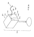
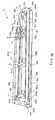
- Figure 3(a) is a perspective view of a surgical device 11, according to one embodiment of the present invention.
- Figures 3(a) to 3(e) illustrate one embodiment of the present invention in which two drive shafts are configured to be employed to move the jaw portion 11a relative to the shaft portion 11b, to rotate the jaw portion 11a about its longitudinal axis, to move the first jaw 50 relative to the second jaw 80, and to fire a stapling and cutting cartridge.
- the jaw portion 11a is positioned at an angle of approximately 60 degrees relative to the shaft portion 11b.
- the jaw portion 11a may be appropriately positioned according to the incision made in the patient and to the position of the tissue desired to be clamped, cut and stapled.
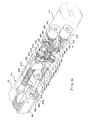
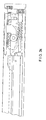
- Figure 3(b) is a rear perspective view that illustrates some of the internal components of the surgical device 11, according to an example embodiment of the present invention.
- the outer body of the surgical device 11 is shown in ghost lines.
- the jaw portion 11a is in an initial position in which it is axially aligned with the shaft portion 11b.
- Figure 3(b) shows a first rotatable drive shaft 500, which may be axially rotatable within the shaft portion 11b. Coupled to the first rotatable drive shaft 500 is a gear element 502. The gear element 502 rotates about a longitudinal axis and is meshingly engaged with a gear element 504. The gear element 504 is held in position by pin 505, the central axis of which is coaxial with the pivot axis B around which the jaw portion 11a pivots relative to the shaft portion 11b.
- the gear element 504 is also meshingly engaged with a gear element 506 within the jaw portion 11a.
- the gear element 506 is connected to a gear element 510 by a shaft 508.
- the gear element 506, the gear element 510, and the shaft 508 rotate within the jaw portion 11a about a longitudinal axis defined by the central axis of the shaft 508.
- the gear element 510 is meshingly engaged with a gear element 512 that rotates about a pin 513 that is longitudinally arranged within the jaw portion 11a.
- the gear element 512 is meshingly engaged with a gear element 514.
- the gear element 514 has a shaft portion that extends distally to a set of teeth 516.
- the teeth 516 are selectively engageable with a correspondingly-shaped opening in a plate 518, the plate 518 being keyed to an internal surface of the surgical device 11 so as to prevent relative rotation of the plate 518.
- the plate 518 is moveable in an axial direction between a first position, in which the correspondingly-shaped opening in the plate 518 is locked in engagement with the teeth 516, and a second position, in which the plate 518 is moved distally relative to the first position and the correspondingly-shaped opening in the plate 518 is not in engagement with the teeth 516.
- a threaded screw 520 Extending distally from the gear 514 and the shaft portion carrying the teeth 516 is a threaded screw 520.
- the threaded screw 520 is arranged longitudinally and is configured to rotate about a longitudinal axis when the gear 514 is rotated.
- Mounted on the threaded screw 520 is a push block 522.
- the push block 522 is keyed to an internal surface of the surgical device 11, so as to prevent relative rotation of the push block 520.
- Rotatably coupled to the lower distal end of the push block 520 is a pair of rollers 524.
- the pair of rollers 524 are seated within respective slots 5011 on each side of the upper jaw 50.
- the upper jaw 50 and the slots 5011 are shown in dotted line in Figure 3(b) .
- Figure 3(b) also shows a second rotatable drive shaft 550, which may be axially rotatable within the shaft portion 11b. Coupled to the second rotatable drive shaft 550 is a gear element 552.
- the gear element 552 rotates about a longitudinal axis and is meshingly engaged with a gear element 554.
- the gear element 554 is held in position by pin 505, the central axis of which is coaxial with the pivot axis B around which the jaw portion 11a pivots relative to the shaft portion 11b.
- the gear element 554 is also meshingly engaged with a gear element 556 within the jaw portion 11a.
- the gear element 556 is connected to a gear element 560 by a shaft 558.
- the gear element 556, the gear element 560, and the shaft 558 rotate within the jaw portion 11a about a longitudinal axis defined by the central axis of the shaft 558.
- the gear element 560 is meshingly engaged with a gear element 562a that is mounted on a proximal end of the pin 513.
- the gear element 562a is configured to adapted to be non-rotatably mounted on, and thus to rotate with, the pin 513, the pin 513 extending longitudinally within the jaw portion 11a.
- a gear element 562b is adapted to be non-rotatably mounted on a distal end of the pin 513.
- the gear element 562b is also configured to rotate with the pin 513.
- the gear element 562b has a shaft portion that extends distally and includes a set of teeth 5661 (hidden from view in Figure 3(b) but shown in Figure 3(d) ).
- the teeth 5661 are selectively engageable with a correspondingly-shaped opening in the plate 518.
- the plate 518 is keyed to an internal surface of the surgical device 11 so as to prevent relative rotation of the plate 518, and is moveable in an axial direction between the first position, in which the correspondingly-shaped opening in the plate 518 is locked in engagement with the teeth 5661, and the second position, in which the plate 518 is moved distally relative to the first position and the correspondingly-shaped opening in the plate 518 is not in engagement with the teeth 5661.
- the gear element 562b is meshingly engaged with a gear element 564.
- a first longitudinal rod 566 Extending distally from the gear 564 is a first longitudinal rod 566.
- the first longitudinal rod 566 is attached to a second longitudinal rod 568.
- the second longitudinal rod 568 has a shoulder 572.
- Between the first longitudinal rod 566 and the shoulder 572 of the second longitudinal rod 568 is a spring.
- the distal end 574 of the second longitudinal rod 568 is configured to engage a respective opening in a wedge driver 605.
- the wedge driver 605 rotates so as to drive a stapling/cutting wedge (described in further detail below) along a staple cartridge.
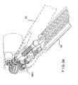
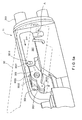
- Figure 3(c) is a side perspective view that illustrates some of the internal components of the surgical device 11. As shown, the jaw portion 11a is pivoted, e.g., articulated, relative to the shaft portion 11b.
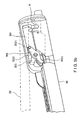
- Figure 3(d) is a perspective view that illustrates the jaw portion 11a being further pivoted, e.g., articulated, relative to the shaft portion 11b.
- Figure 3(e) is a bottom perspective view that illustrates the jaw portion 11a being pivoted, e.g., articulated, relative to the shaft portion 11b.
- the surgical device 11 may also include a cutting and stapling element 104.
- the staple and cutting element 104 is a staple cartridge.
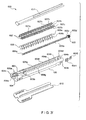
- Figure 3(f) is an exploded view of a replaceable staple cartridge 600.
- the replaceable staple cartridge 600 is one type of stapling/cutting arrangement that may be employed as the cutting and stapling element 104 in the example embodiment of the present invention illustrated in Figures 3(a) to 3(e) .
- the replaceable staple cartridge 600 includes a staple tray 604.
- the staple tray 604 has a slot 604i at its proximal end 604d in which the memory module 6041 is retained by a memory module retainer 6042.
- the memory module 6041 may store information as described, for example, in U.S.
- a wedge driver 605 is configured to be rotatably disposed through a central channel 604e of the staple tray 604. Specifically, the wedge driver 605 has a distal end 605a that is configured to be rotatably mounted within a distal orifice 604a of the staple tray 604.
- the wedge driver 605 also includes an externally threaded region 605b, a non-threaded portion 605c that rotatably extends through a proximal orifice 604b in the proximal end 604b of the staple tray 604, and a proximally-facing opening 605d at its proximal-most end for receiving the distal end 574 of the second longitudinal rod 568.
- the proximally-facing opening 605d and the distal end 574 of the second longitudinal rod 568 are adapted for non-rotatable coupling relative to each other when the distal end 574 of the second longitudinal rod 568 is received, e.g., inserted, within the proximally-facing opening 605d.
- the replaceable staple cartridge 600 also includes a wedge 603 having an internally threaded bore 603a.
- the externally threaded region 605b of the wedge driver 605 is configured to extend through the internally threaded bore 603a of the wedge 603.
- the threads of the internally threaded bore 603a of the wedge 603 match the threads of the externally threaded region 605b of the wedge driver 605.
- the wedge 603 is moved between the distal end 604c of the staple tray 604 and the proximal end 604d of the staple tray 604 through a central channel 604e.
- the staple tray 604 also includes a plurality of vertically-disposed slots 604f in opposing walls 604g of the central channel 604e.
- a staple pusher 607 is configured to be slideably disposed within the slots 604f. More specifically, each of the staple pushers 607 has a top surface 607a running longitudinally between two rows 607b of staple pushing fingers 607c.
- the staple pushing fingers 607c are configured such that each staple pushing finger 607c in the row 607b that abuts the wall 604g of the staple tray 604 is retained within a corresponding slot 604f of the wall 604g so as to be vertically slideable therein.
- the staple pushing fingers 607c are positioned over slots 604h in the staple tray 604.
- the slots 604h in the staple tray 604 house a plurality of fasteners, e.g., staples 606.
- Each of the staples 606 includes a butt 606a and a pair of prongs 606b.
- the wedge 603 also includes a pair of sloped edges 603b that slideably engage respective top surfaces 607a of the staple pushers 607.
- the pair of sloped edges 603b of the wedge 603 is configured to slideably engage the respective top surfaces 607a of the staple pushers 607 in order to successively push the staple pushing fingers 607c of the staple pushers 607 into, and thus the staples 606 out of, the slots 604h in the staple tray 604.
- a cartridge top 611 is configured to fit over the central channel 604a of the staple tray 604, while a staple retainer 610 is configured to cover the clamping surface 106 of the staple tray 604. Additional features, e.g., a blade 51, of the staple cartridge 600 are described below in connection with Figure 3(g) , these features being described during operation of the surgical device 11.
- Figure 3(h) is a bottom view of the first jaw 50.
- the first jaw 50 includes an anvil member 700 having a longitudinally-disposed slot 701 that extends from a distal end to a proximal end of the anvil member 700.
- the slot 701 is aligned with the blade 51 of the second jaw 80 so that the blade 51 extends into and travels along the slot 701 when the blade is moved from the distal end 80a to the proximal end 80b of the second jaw 80.
- the anvil member 700 also includes a plurality of rows 702 of staple guides 703.
- the staple guides 703 are configured to receive the prongs 606b of the staples 606 and to bend the prongs 606b so as to close the staples 606.
- the rows 702 of the staple guides 703 align with the slots 604h of the staple tray 604 in the second jaw 80.
- the jaw portion 11a is maintained in an initial position in which it is axially aligned with the shaft portion 11b, such as the position shown in Figure 3(b) .
- the surgical device 11 may be inserted, e.g., through a trocar, into a surgical site.
- the user may then articulate the jaw portion 11a relative to the shaft portion 11b.
- the jaw portion 11a is pivoted relative to the shaft portion 11b.
- the plate 518 is arranged in its first position, e.g., such that the two openings in the plate 518 are locked in respective engagement with the teeth 516 of gear element 514 and with the teeth 5661 of the gear element 562b.
- the first rotatable drive shaft 500 and the second rotatable drive shaft 550 are then rotated in opposite directions.
- the first rotatable drive shaft 500 may be rotated in a counter-clockwise direction (for the sake of simplicity, all references herein to a rotational direction, e.g., clockwise or counterclockwise, refer to a view from the proximal end of the surgical device towards the distal end of the surgical device 11, unless otherwise noted).
- the gear element 502 attached to the first rotatable drive shaft 500 is thus also caused to rotate in a counter-clockwise direction.
- the counter-clockwise rotation of the gear element 502 causes the gear element 504 to rotate in a counter-clockwise direction (when viewed from above) about the pin 505.
- the counter-clockwise rotation of the gear element 504 causes the gear element 506 to rotate in a clockwise direction.
- the second rotatable drive shaft 550 may be rotated in a clockwise direction.
- the gear element 552 attached to the second rotatable drive shaft 550 is thus also caused to rotate in a clockwise direction.
- the clockwise rotation of the gear element 552 causes the gear element 554 to rotate in a counter-clockwise direction (when viewed from above) about the pin 505.
- the clockwise rotation of the gear element 554 causes the gear element 556 to rotate in a counter-clockwise direction.
- the engagement of the plate 518 with the teeth 516 and 5661 prevents the rotation of the gear elements 506 and 566 relative to the surgical device 11.
- the jaw portion 11a is caused to rotate in a clockwise direction relative to the shaft portion 11b (when viewed from above).
- the opposite direction e.g., counter-clockwise relative to the shaft portion 11b when viewed from above.
- the jaw portion 11a may also be rotated, in a second articulation process, relative to the shaft portion 11b about the longitudinal axis of the jaw portion 11a, e.g., illustrated as axis D.
- the plate 518 is maintained in its first position, such that the two openings in the plate 518 are locked in respective engagement with the teeth 516 of gear element 514 and with the teeth 5661 of the gear element 562b.
- the first rotatable drive shaft 500 and the second rotatable drive shaft 550 are then rotated in the same direction.
- the first rotatable drive shaft 500 may be rotated in a counter-clockwise direction.
- the gear element 502 attached to the first rotatable drive shaft 500 is thus also caused to rotate in a counter-clockwise direction.
- the counter-clockwise rotation of the gear element 502 causes the gear element 504 to rotate in a counter-clockwise direction (when viewed from above) about the pin 505.
- the counter-clockwise rotation of the gear element 504 causes the gear element 506 to rotate in a clockwise direction.
- gear element 506 Since the gear element 506 is attached to the gear element 510 by the shaft 508, rotation of the gear element 506 in the clockwise direction causes the gear element 510 to also rotate in a clockwise direction. By virtue of its engagement with the gear element 512, the clockwise rotation of the gear element 510 causes the gear element 512 to rotate in a counter-clockwise direction.
- the second rotatable drive shaft 550 may also be rotated in a counter-clockwise direction.
- the gear element 552 attached to the second rotatable drive shaft 550 is thus also caused to rotate in a counter-clockwise direction.
- the counter-clockwise rotation of the gear element 552 causes the gear element 554 to rotate in a clockwise direction (when viewed from above) about the pin 505.
- the clockwise rotation of the gear element 554 causes the gear element 556 to rotate in a clockwise direction. Since the gear element 556 is attached to the gear element 560 by the shaft 558, rotation of the gear element 556 in the clockwise direction causes the gear element 560 to also rotate in a clockwise direction.
- both the gear element 562a and the gear element 562b are adapted to be non-rotatably mounted to, e.g., keyed to, the pin 513, the rotation of the gear element 562a in a counter-clockwise direction also causes the gear element 562b to rotate in a counter-clockwise direction.
- the gear element 562b and the gear element 512 rotate together in a counter-clockwise direction about their shared longitudinal axes, e.g., the central axis of the pin 513. Since the plate 518 is maintained in its first position, the two openings in the plate 518 are locked in respective engagement with the teeth 516 of gear element 514 and with the teeth 5661 of the gear element 562b. Thus, the rotation of the gear element 562b, and of the gear element 512 in the counter-clockwise direction about the pin 513, causes the gear element 514 and the gear element 564 to also rotate in a counter-clockwise direction about the pin 513, the central axis of which is coaxial with the longitudinal axis D of the jaw portion 11a.
- the gear element is connected to the screw 520, on which is mounted the push block 522. Since the push block 522 is keyed to the internal surface of the jaw portion 11a, the rotation of the gear element 514 about the longitudinal axis D causes the jaw portion 11a to rotate relative to the shaft portion 11b about its longitudinal axis D.
- the jaws 50, 80 may be opened so as to enable a section of tissue to be disposed therebetween.
- the plate 518 is moved distally to its second position, such that the two openings in the plate 518 are not locked in respective engagement with either the teeth 516 of gear element 514 nor with the teeth 5661 of the gear element 562b.
- the first rotatable drive shaft 500 is then rotated in a first direction while the second rotatable drive shaft 550 is not rotated.
- the first rotatable drive shaft 500 may be rotated in a counter-clockwise direction.
- the gear element 502 attached to the first rotatable drive shaft 500 is thus also caused to rotate in a counter-clockwise direction.
- the counter-clockwise rotation of the gear element 502 causes the gear element 504 to rotate in a counter-clockwise direction (when viewed from above) about the pin 505.
- the counter-clockwise rotation of the gear element 504 causes the gear element 506 to rotate in a clockwise direction.
- gear element 506 Since the gear element 506 is attached to the gear element 510 by the shaft 508, rotation of the gear element 506 in the clockwise direction causes the gear element 510 to also rotate in a clockwise direction. By virtue of its engagement with the gear element 512, the clockwise rotation of the gear element 510 causes the gear element 512 to rotate in a counter-clockwise direction. By virtue of its engagement with the gear element 514, the counter-clockwise rotation of the gear element 512 causes the gear element 514 to rotate in a clockwise direction. Since the plate 518 is moved to its second position, the gear element 512 rotates about the pin 513 without the pin 513 rotating.
- the clockwise rotation of the gear element 514 causes rotation of the threaded screw 520 in a clockwise direction.
- the push block 522 In an initial stage of operation, e.g., when the surgical device 11 has first been inserted into a patient's body, the push block 522 is located in a distal-most position along the threaded screw 520. Rotation of the threaded screw 520 causes the push block 522, which is adapted to be non-rotatably mounted within, e.g., keyed to, an internal surface of the surgical device 11, to travel in a proximal direction. The proximal movement of the push block 522 causes the pair of rollers 524 to move proximally within their respective slots 5011 on each side of the upper jaw 50.
- the rollers 524 are positioned at a proximal end of the slots 5011, at which position the first jaw 50 is maximally opened relative to the second jaw 80.
- the jaws 50, 80 are closed so as to clamp a section of tissue therebetween.
- the plate 518 in its second position, e.g., such that the two openings in the plate 518 are not locked in respective engagement with either the teeth 516 of gear element 514 nor with the teeth 5661 of the gear element 562b, the first rotatable drive shaft 500 is rotated in a second direction while the second rotatable drive shaft 550 is not rotated.
- the first rotatable drive shaft 500 may be rotated in a clockwise direction.
- the gear element 502 attached to the first rotatable drive shaft 500 is thus also caused to rotate in a clockwise direction.
- the clockwise rotation of the gear element 502 causes the gear element 504 to rotate in a clockwise direction (when viewed from above) about the pin 505.
- the clockwise rotation of the gear element 504 causes the gear element 506 to rotate in a counter-clockwise direction. Since the gear element 506 is attached to the gear element 510 by the shaft 508, rotation of the gear element 506 in the counter-clockwise direction causes the gear element 510 to also rotate in a counter-clockwise direction.
- the counter-clockwise rotation of the gear element 510 causes the gear element 512 to rotate in a clockwise direction.
- the clockwise rotation of the gear element 512 causes the gear element 514 to rotate in a counter-clockwise direction. Since the plate 518 is moved to its second position, the gear element 512 rotates about the pin 513 without the pin 513 rotating.
- the counter-clockwise rotation of the gear element 514 causes rotation of the threaded screw 520 in a counter-clockwise direction.
- the push block 522 may be located in a proximal-most position along the threaded screw 520. Rotation of the threaded screw 520 causes the push block 522, which is keyed to an internal surface of the surgical device 11, to travel in a distal direction. The distal movement of the push block 522 causes the pair of rollers 524 to move distally within their respective slots 5011 on each side of the upper jaw 50.
- the rollers 524 are positioned at a distal end of the slots 5011, at which position the first jaw 50 is maximally clamped against the second jaw 80. It should be noted that, while the opening and closing of the first and second jaws 50, 80 may occur in a simple scissor type fashion, in other embodiments, the first and second jaws 50, 80 may open and close in a different manner. An example of one such type of movement is described in additional detail below in connection with Figures 3(f) through 3(i) .
- the surgical device 11 may employ only one such element, or else may employ a different type of surgical instrument.
- a staple cartridge 578 is provided within the second jaw 80.
- the surgical device 11 is a single use device, in which the staple cartridge is integral to the second jaw 80.
- the surgical device 11 may have a replaceable staple cartridge, e.g., replaceable staple cartridge 600 as illustrated in Figure 3(f) , thereby permitting the surgical device 11 to be used numerous times with different staple cartridges.
- the staple cartridge 600 may be pre-installed during manufacture and assembly of the surgical device 11, or else may be installed by the user just prior to using the surgical device 11. If the surgical device 11 is being used for the second or more time, the staple cartridge 600 may be installed by the user just prior to using the surgical device 11.
- the staple cartridge 600 When the staple cartridge 600 is inserted into the second jaw 80, the distal end 574 of the longitudinal rod 568 is received within the proximally facing opening 605d of the wedge driver 605.
- FIG. 3(b) To illustrate the cutting/stapling operation of the surgical device 11, reference is first made to Figure 3(b) .
- the plate 518 With the staple cartridge 600 installed within the second jaw 80 of the surgical device 11, the plate 518 is maintained in its second position, such that the two openings in the plate 518 are not locked in respective engagement with either the teeth 516 of gear element 514 nor with the teeth 5661 of the gear element 562b.
- the second rotatable drive shaft 550 is then rotated in a first direction while the first rotatable drive shaft 500 is not rotated. For instance, in order to cut and staple a section of tissue disposed between the first and second jaw 50, 80, the second rotatable drive shaft 550 may be rotated in a counter-clockwise direction.
- the gear element 552 attached to the second rotatable drive shaft 550 is thus also caused to rotate in a counter-clockwise direction.
- the counter-clockwise rotation of the gear element 552 causes the gear element 554 to rotate in a clockwise direction (when viewed from above) about the pin 505.
- the clockwise rotation of the gear element 554 causes the gear element 556 to rotate in a clockwise direction. Since the gear element 556 is attached to the gear element 560 by the shaft 558, rotation of the gear element 556 in the clockwise direction causes the gear element 560 to also rotate in a clockwise direction.
- the clockwise rotation of the gear element 560 causes the gear elements 562a and 562b to rotate in a counter-clockwise direction.
- the counter-clockwise rotation of the gear element 562b causes the gear element 564 to rotate in a clockwise direction. Since the plate 518 is moved to its second position, the gear element 562b rotates with the pin 513 without the gear element 514 rotating.
- the clockwise rotation of the gear element 564 causes rotation of the first longitudinal rod 566 along with the second longitudinal rod 568 in the clockwise direction.
- the spring 570 that resides between a distal end of the first longitudinal rod 566 and a shoulder 572 of the second longitudinal rod 568 functions to bias the second longitudinal rod 568 in a distal direction, thereby insuring that the distal end 574 of the second longitudinal rod 568 seats within its respective opening 605d of the wedge driver 605.
- Figure 3(g) is a cross-sectional view of the surgical device 11, according to one embodiment of the present invention, in a fully closed position.
- the surgical device 11 is illustrated absent a section of tissue between the clamping surfaces 106, 108 of the first and the second jaws 50, 80.
- the surgical device 11 is disposed within the second jaw 80, and the cutting and stapling element 104 includes the replaceable staple cartridge 600 of Figure 3(g) that is replaceably mountable within the second jaw 80.
- the replaceable staple cartridge 600 which was shown in an exploded view in Figure 3(f) , is shown assembled and mounted within the second jaw 80 in Figure 3(g) .
- the wedge 603 has disposed thereon a blade 51 having a cutting edge 51a.
- the cutting and stapling elements may be separately disposed.
- the blade 51 has a tail region 654 with a contact face 653.
- the blade 51 is rotatably coupled to the wedge 603 around pivot 51b to allow the blade 51 to rotate between a first and a second position.
- Figure 3(g) illustrates the wedge 603 and the blade 51 in several positions, labeled as positions A to E, as the wedge 603 and the blade 51 travel from the distal end 604c to the proximal end 604d of the staple tray 604.
- the wedge 603 and the blade 51 are positioned at the distal end 604c of the staple tray 604.
- the wedge 603 and the blade 51 are housed within a housing 615 and the blade 51 is rotated relative to the wedge 603 so as to be in a retracted position, e.g., the cutting edge 51a facing upwards and is not exposed.
- the contact face 653 initially faces the proximal end 604d of the staple tray 604.
- rotation of the wedge driver 605 via the distal end 574 of the second longitudinal rod 568 causes the wedge 603 and the blade 51 to advance to the position labeled B, via.
- the wedge 603 and the blade 51 are positioned proximally relative to the distal end 604c of the staple tray 604.
- the wedge 603 and the blade 51 are positioned such that the contact face 653 of the blade 51 begins to contact an actuating lip 615a of the housing 615.
- the blade 51 begins to rotate relative to the wedge 603.
- the blade 51 When the contact face 653 of the blade 51 has fully contacted the actuating lip 615a of the housing 615, the blade 51 is fully rotated relative to the wedge 603 such that the cutting edge 51a of the blade 51 is in an extended position, e.g., the cutting edge 51a faces the proximal end 604d of the staple tray 604.
- the staples 606 housed within the staple tray 604 may simultaneously be fired with the movement of the blade 51 from the proximal end 80b to the distal end 80a of the second jaw 80. For instance, rotation of the wedge driver 605 via the distal end 574 of the second longitudinal rod 568 causes the wedge 603 to be moved through the central channel 604e of the staple tray 604.
- the pair of sloped edges 603b of the wedge 603 slideably engage the respective top surfaces 607a of the staple pushers 607 and successively push the staple pushing fingers 607c of the staple pushers 607 into, and thus the staples 606 out of, the slots 604h in the staple tray 604.
- the rows 702 of the staple guides 703 align with the slots 604h of the staple tray 604 in the second jaw 80 so that the staples 606 maintained in the slots 604h of the staple tray 604 are pushed by the staple pushing fingers 607c of the staple pushers 607 into, and closed by, corresponding staple guides 703 of the anvil member 700.
- the staple guides 703 receive the prongs 606b of the staples 606 when the surgical device 11 is fired and bend the prongs 606b so as to close the staples 606, thereby stapling the section of tissue.
- the blade 51 and the wedge 603 may be moved in either a proximal or a distal direction in order to cut a section of tissue disposed between the first jaw 50 and the second jaw 80.
- any mechanical arrangement that is configured to move the blade 51 and the wedge 603 in order to cut and/or staple a section of tissue disposed between the first jaw 50 and the second jaw 80 may be employed.
- first and second jaws 50, 80 may open and close in a different manner.
- An example of one such type of movement is described generally below in connection with Figures 3(i) through 3(l) . Further details and benefits of this type of movement are described in Patent Appl. Serial No. 10/460,291, filed June 11, 2003 .
- those components of the surgical device 11 that are located proximal to the gear element 514 and the gear element 564 are not shown. It should be understood that these gear elements 514, 564 may be driven by the combination of drive components illustrated in Figures 3(a) through 3(e) , or by any other combination of driving components.
- Figure 3(i) illustrates the first jaw 50 in an open position relative to the second jaw 80.
- the push block 522 is at or near a proximal end of the threaded screw 520, and the rollers 524 attached to the push block 522 are positioned at or near the proximal end of slots 5011 of the first jaw 50.
- the first jaw 50 includes a pivot pin 5012, which is engaged within a vertical slot 5013 of the second jaw 80.
- the proximal ends 50b, 80b of the first and second jaws 50, 80, respectively, are biased apart from each other, such that, in the initial position shown in Figure 3(i) , the pin 5012 is positioned at the lower end of the slot 5013.
- FIG. 4(a) is a perspective view of the surgical device 11, according to another embodiment of the present invention, which employs a different mechanism for moving the first jaw 50 relative to the second jaw 80.
- Figure 4(b) is a perspective view that illustrates additional features of the second jaw 80 of the jaw portion 11a.
- the first jaw 50 is shown in ghost lines.
- Figure 4(b) illustrates portions of the first driver 88, e.g., a horizontal driver element 301 that is connected to a first rotatable clamping element 302. These and other features of the first driver 88, according to this embodiment, are further illustrated in Figures 5(a) to 5(d) .
- Figure 5(a) is a perspective view that illustrates the proximal end 80b of the second jaw 80.
- the proximal end 50b of the first jaw 50 is shown in ghost lines.
- Figure 5(a) illustrates the surgical device 11 in a fully open position.
- the first driver 88 includes a rotating shaft 303.
- the first driver 88 also includes the horizontal driver element 301.
- a proximal end of the horizontal driver element 301 is engaged by the rotating shaft 303.
- a distal end of the horizontal driver element 301 includes an opening 3011.
- the first driver 88 also includes a first rotatable clamping element 302.
- the first rotatable clamping element 302 has a proximal end 3021, a middle portion 3022 and a distal end 3023.
- the first driver 88 also includes a second rotatable clamping element 303.
- the second rotatable clamping element 303 has a proximal end 3032 and a distal end 3031.
- the proximal end of the first rotatable clamping element 302 is pivotably connected to the opening 3011 at the distal end of the horizontal driver element 301.
- the middle portion 3022 of the first rotatable clamping element 302 is pivotably connected to the proximal end 3032 of the second rotatable clamping element 303.
- the distal end 3021 of the first rotatable clamping element 302 is pivotably connected to the first jaw 50.
- the distal end 3031 of the second rotatable clamping element 303 is pivotably connected to the second jaw 50.
- the proximal end 50b of the first jaw 50 is pivotably connected to the proximal end 80b of the second jaw 80 around pivot point A.
- the surgical device 11 Upon engagement of the first driver 88, the surgical device 11 is moved into a first partially closed position, as illustrated in Figure 5(b) .
- the first drive shaft 94 causes rotation of the first drive socket 654 in a first direction.
- Rotation of the first drive socket 654 causes rotation of the rotating shaft 303 of the first driver 88, which in turn causes the horizontal driver element 301 to move in a distal direction.
- the components of the first driver 88 while described in connection with this embodiment as including a rotating shaft 303, may include some or all of the components described in connection with the embodiment illustrated in Figure 3(a) through 3(e) as set forth above, or else may include any other arrangement of components suitable for moving the horizontal driver element 301 in a distal direction driving.
- distal movement of the horizontal driver element 301 causes rotation of the first rotatable clamping element 302, such that the distal end 3023 of the second rotatable clamping element 302 begins to move in a downward direction.
- the downward movement of the distal end 3023 of the second rotatable clamping element 302 by virtue of its pivotable attachment to the first jaw 50, causes the first jaw 50 to rotate relative to the second jaw 80 around pivot point A into the partially closed position.
- the surgical device 11 Upon further engagement of the first driver 88, the surgical device 11 is moved into a second partially closed position, as illustrated in Figure 5(c) .
- the horizontal driver element 301 is caused to move in a still further distal direction via the rotation of the first drive shaft 94, the first drive socket 654 and the rotating shaft 303 of the first driver 88.
- Continued distal movement of the horizontal driver element 301 causes further rotation of the first rotatable clamping element 302, such that the distal end 3023 of the second rotatable clamping element 302 continues to move in a downward direction.
- the continued downward movement of the distal end 3023 of the second rotatable clamping element 302 by virtue of its pivotable attachment to the first jaw 50, causes the first jaw 50 to rotate relative to the second jaw 80 around pivot point A into a nearly fully closed position.
- the surgical device 11 Upon further engagement of the first driver 88, the surgical device 11 is moved into a fully closed position, as illustrated in Figure 5(d) .
- the horizontal driver element 301 is caused to move to a fully distal position via the rotation of the first drive shaft 94, the first drive socket 654 and the rotating shaft 303 of the first driver 88.
- the first rotatable clamping element 302 In the fully distal position, the first rotatable clamping element 302 is fully rotated, such that the distal end 3023 of the first rotatable clamping element 302 is in a fully lowered position.
- the distal end 3023 of the first rotatable clamping element 302 has moved the first jaw 50 around pivot point A to a fully closed position, such that a section of tissue 52 disposed between the first and second jaws 50, 80 is fully clamped between the first and second jaws 50, 80.
- the surgical device 11 may be configured as an attachment to, or may be integral with, a purely mechanical device driver system, such as that illustrated in Figure 1 .
- the surgical device 11 may be configured as an attachment to, or may be integral with, an electro-mechanical surgical system, such as an electro-mechanical driver system 1610 illustrated in Figure 2(a) .
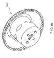
- Figure 2(a) is a perspective view of an example embodiment of an electro-mechanical driver component 1610 according to the present invention.
- an electro-mechanical surgical system is described in, e.g., U.S. Patent Application Serial No. 09/723,715, filed on November 28, 2000 , now issued as U.S. Patent No. 6,793,652 on September 21, 2004 , U.S. Patent Application Serial No. 09/836,781, filed on April 17, 2001 , U.S. Patent Application Serial No. 09/887,789, filed on June 22, 2001 and U.S. Patent Application Serial No. 10/099,634, filed on March 15, 2002 .
- the electro-mechanical driver component 1610 may include, for example, a remote power console 1612, which includes a housing 1614 having a front panel 1615. Mounted on the front panel 1615 are a display device 1616 and indicators 1618a, 1618b.
- a flexible shaft 1620 may extend from the housing 1614 and may be detachably attached thereto via a first coupling 1622.
- the distal end 1624 of flexible shaft 1620 may include a second coupling 1626 adapted to detachably couple, e.g., the surgical device 11 described above, to the distal end 1624 of the flexible shaft 1620.
- the second coupling 1626 may also be adapted to detachably attach a different surgical instrument or attachment.
- the distal end 1624 of the flexible shaft 1620 may permanently attach to or be integral with a surgical instrument.
- Figures 6(a) through 6(e) illustrate, according to one embodiment of the present invention, an arrangement of couplings and flexible shaft that may be employed in order to connect the surgical device 11 to the electro-mechanical drive component 1610.
- Figure 6(a) illustrates a flexible shaft 2620 that extends from the housing 1614 that is detachably attached thereto via a first coupling 2622.
- the distal end 2624 of flexible shaft 2620 may include a second coupling 2626 adapted to detachably couple, e.g., the surgical device 11 described above, to the distal end 2624 of the flexible shaft 2620.
- Figure 6(b) illustrates a rear perspective view of the first coupling 2622, according to one embodiment of the present invention.
- Figure 6(c) illustrates a front perspective view of the first coupling 2622, according to the embodiment shown in Figure 6(b) .
- Figure 6(d) is a side perspective view of some of the internal components of the first coupling 2622.
- Figure 6(e) is a rear perspective view of the second coupling 2626 at the distal end 2624 of the flexible shaft 2620, according to one embodiment of the present invention.
- the flexible shaft 2620 is shown in Figure 6(e) as ghost lines. Additional features of these components are further described in U.S. Provisional Patent App. No. 60/703,227 and U.S. Patent Application Serial No. 11/495,920 .
- the flexible shaft 2620 and couplings 2622, 2626 provide one arrangement by which the surgical device 11 may be attached to the electro-mechanical power console 1610
- any suitable arrangement may be employed.
- Figures 7 through 10 illustrate another arrangement by which the surgical device 11 may be attached to the electro-mechanical power console 1610.
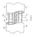
- the flexible shaft 1620 includes a tubular sheath 1628, which may include a coating or other sealing arrangement configured to provide a fluid-tight seal between the interior channel 1640 thereof and the environment.
- the sheath 1628 may be formed of a tissue-compatible, sterilizable elastomeric material.
- the sheath 1628 may also be formed of a material that is autoclavable. Disposed within the interior channel 1640 of the flexible shaft 1620, and extending along the entire length thereof, may be a first rotatable drive shaft 94, a second rotatable drive shaft 102, a first steering cable 1634, a second steering cable 1635, a third steering cable 1636, a fourth steering cable 1637 and a data transfer cable 1638.
- Figure 8 is a cross-sectional view of the flexible shaft 1620 taken along the line 8-8 illustrated in Figure 7 and further illustrates the several cables 94, 102, 1634, 1635, 1636, 1637 and 1638.
- Each distal end of the steering cables 1634, 1635, 1636, 1637 is affixed to the distal end 1624 of the flexible shaft 1620.
- Each of the several cables 94, 102, 1634, 1635, 1636, 1637, 1638 may be contained within a respective sheath.
- the first rotatable drive shaft 94 and the second rotatable drive shaft 102 may be configured, for example, as highly flexible drive shafts, such as, for example, braided or helical drive cables. It should be understood that such highly flexible drive cables may have limited torque transmission characteristics and capabilities. It should also be understood that the surgical device 11, or other attachments connected to the flexible shaft 1620, may require a higher torque input than the torque transmittable by the drive shafts 94, 102.
- the drive shafts 94, 102 may thus be configured to transmit low torque but high speed, the highspeed/low-torque being converted to low-speed/high-torque by gearing arrangements disposed, for example, at the distal end and/or the proximal end of the drive flexible shaft 1620, in the surgical instrument or attachment and/or in the remote power console 1612.
- gearing arrangement(s) may be provided at any suitable location along the power train between the motors disposed in the housing 1614 and the attached surgical instrument or other attachment connected to the flexible shaft 1620.
- Such gearing arrangement(s) may include, for example, a spur gear arrangement, a planetary gear arrangement, a harmonic gear arrangement, cycloidal drive arrangement, an epicyclic gear arrangement, etc.
- the first coupling 1622 includes a first connector 1644, a second connector 1648, a third connector 1652 and a fourth connector 1656, each rotatably secured to the first coupling 1622.
- Each of the connectors 1644, 1648, 1652, 1656 includes a respective recess 1646, 1650, 1654, 1658. As illustrated in Figure 9 , each recess 1646, 1650, 1654, 1658 may be hexagonally shaped.
- the recesses 1646, 1650, 1654, 1658 may have any shape and configuration adapted to non-rotatably couple and rigidly attach the connectors 1644, 1648, 1652, 1656 to respective drive shafts of the motor arrangement contained within the housing 1614.
- complementary projections may be provided on respective drive shafts of the motor arrangement to thereby drive the drive elements of the flexible shaft 1620.
- the recesses may be provided on the drive shafts and complementary projections may be provided on the connectors 1644, 1648, 1652, 1656. Any other coupling arrangement configured to non-rotatably and releasably couple the connectors 1644, 1648, 1652, 1656 and the drive shafts of the motor arrangement may be provided.
- the data transfer cable 1638 is electrically and logically connected with data connector 1660.
- the data connector 1660 includes, for example, electrical contacts 1662, corresponding to and equal in number to the number of individual wires contained in the data cable 1638.
- the first coupling 1622 includes a key structure 1642 configured to properly orient the first coupling 1622 to a mating and complementary coupling arrangement disposed on the housing 1612.
- the key structure 1642 may be provided on either one, or both, of the first coupling 1622 and the mating and complementary coupling arrangement disposed on the housing 1612.
- the first coupling 1622 may include a quick-connect type connector, which may engage the first coupling 1622 to the housing 1612 by a simple pushing motion. Seals may be provided in conjunction with any of the several connectors 1644, 1648, 1652, 1656, 1660 to provide a fluid-tight seal between the interior of first coupling 1622 and the environment.
- the second coupling 1626 includes a first connector 1666 and a second connector 1668, each rotatably secured to the second coupling 1626 and each non-rotatably secured to a distal end of a respective one of the first and second drive shafts 94, 102.
- a quick-connect type fitting 1664 is provided on the second coupling 1626 to detachably secure the device 11 thereto.
- the quick-connect type fitting 1664 may be, for example, a rotary quick-connect type fitting, a bayonet type fitting, etc. and may be a fitting complementary to the quick connect sleeve 713 illustrated in Figure 2(b) .
- a key structure 1674 may be provided on the second coupling 1626 and may be configured to properly align the surgical device 11 to the second coupling 1626.
- the key structure or other arrangement configured to properly align the surgical device 11 to the flexible shaft 1620 may be provided on either one, or both, of the second coupling 1626 and the surgical device 11.
- the key structure may be provided on the device 11, as illustrated in Figure 2(b) as the slots 713a of the quick connect sleeve 713.
- a data connector 1670 having electrical contacts 1672 is also provided in the second coupling 1626.
- the data connector 1670 of the second coupling 1626 includes contacts 1672 electrically and logically connected to the respective wires of the data transfer cable 1638 and the contacts 1662 of the data connector 1660. Seals may be provided in conjunction with the connectors 1666, 1668, 1670 to provide a fluid-tight seal between the interior of the second coupling 1626 and the environment.
- electro-mechanical driver elements Disposed within the housing 1614 of the remote power console 1612 are electro-mechanical driver elements configured to drive the drive shafts 94, 102 and the steering cables 1634, 1635, 1636, 1637 to thereby operate the electro-mechanical driver component 1610 and the surgical device 11 attached to the second coupling 1626.
- five electric motors 96, 100, 1684, 1690, 1696 each operated via a power source, may be disposed in the remote power console 1612. It should be appreciated, however, that any appropriate number of motors may be provided, and the motors may operate via battery power, line current, a DC power supply, an electronically controlled DC power supply, etc. It should also be appreciated that the motors may be connected to a DC power supply, which is in turn connected to line current and which supplies the operating current to the motors.
- FIG 11 illustrates schematically one possible arrangement of motors.
- An output shaft 1678 of a first motor 96 engages with the first connector 1644 of the first coupling 1622 when the first coupling 1622, and, therefore, the flexible shaft 1620, is engaged with the housing 1614 to thereby drive the first drive shaft 94 and the first connector 1666 of the second coupling 1626.
- an output shaft 1682 of a second motor 100 engages the second connector 1648 of the first coupling 1622 when the first coupling 1622, and, therefore, flexible shaft 1620 is engaged with the housing 1614 to thereby drive the second drive shaft 102 and the second connector 1668 of the second coupling 1626.
- An output shaft 1686 of a third motor 1684 engages the third connector 1652 of the first coupling 1622 when the first coupling 1622, and, therefore, the flexible shaft 1620, is engaged with the housing 1614 to thereby drive the first and second steering cables 1634, 1635 via a first pulley arrangement 1688.
- An output shaft 1692 of a fourth motor 1690 engages the fourth connector 1656 of the first coupling 1622 when the first coupling 1622, and, therefore, the flexible shaft 1620, is engaged with the housing 1614 to thereby drive the third and fourth steering cables 1636, 1637 via a second pulley arrangement 1694.
- the third and fourth motors 1684, 1690 may be secured on a carriage 1100, which is selectively movable via an output shaft 1698 of a fifth motor 1696 between a first position and a second position to selectively engage and disengage the third and fourth motors 1684, 1690 with the respective pulley arrangement 1688, 1694 to thereby permit the flexible shaft 1620 to become taut and steerable or limp as necessary. It should be appreciated that other mechanical, electrical and/or electro-mechanical mechanisms, etc., may be used to selectively engage and disengage the steering mechanism.
- the motors may be arranged and configured as described, for example, in U.S. Patent Application Serial No.
- any one or more of the motors 96, 100, 1684, 1690, 1696 may be, for example, a highspeed/low-torque motor, a low-speed/high-torque motor, etc.
- the first rotatable drive shaft 94 and the second rotatable drive shaft 102 may be configured to transmit high speed and low torque.
- the first motor 96 and the second motor 100 may be configured as high-speed/low-torque motors.
- first motor 96 and the second motor 100 may be configured as low-speed/high-torque motors with a torque-reducing/speed-increasing gear arrangement disposed between the first motor 96 and the second motor 100 and a respective one of the first rotatable drive shaft 94 and the second rotatable drive shaft 102.
- torque-reducing/speed-increasing gear arrangements may include, for example, a spur gear arrangement, a planetary gear arrangement, a harmonic gear arrangement, cycloidal drive arrangement, an epicyclic gear arrangement, etc. It should be appreciated that any such gear arrangement may be disposed within the remote power console 1612 or in the proximal end of the flexible shaft 1620, such as, for example, in the first coupling 1622. It should be appreciated that the gear arrangement(s) may be provided at the distal and/or proximal ends of the first rotatable drive shaft 94 and/or the second rotatable drive shaft 102 to prevent windup and breakage thereof.
- a controller 1122 is provided in the housing 1614 of remote power console 1612 and is configured to control all functions and operations of the electro-mechanical driver component 1610 and the linear clamping, cutting and stapling device 11 or other surgical instrument or attachment attached to the flexible shaft 1620.
- a memory unit 1130 is provided and may include memory devices, such as, a ROM component 1132 , a RAM component 1134, etc.
- the ROM component 1132 is in electrical and logical communication with the controller 1122 via a line 1136
- the RAM component 1134 is in electrical and logical communication with controller 1122 via line 1138.
- the RAM component 1134 may include any type of random-access memory, such as, for example, a magnetic memory device, an optical memory device, a magneto-optical memory device, an electronic memory device, etc.
- the ROM component 1132 may include any type of read-only memory, such as, for example, a removable memory device, such as a PC-Card or PCMCIA-type device. It should be appreciated that the ROM component 1132 and the RAM component 1134 may be configured as a single unit or may be separate units and that the ROM component 1132 and/or the RAM component 1134 may be provided in the form of a PC-Card or PCMCIA-type device.
- the controller 1122 is further connected to the front panel 1615 of the housing 1614 and, more particularly, to the display device 1616 via a line 1154 and the indicators 1618a, 1618b via respective lines 1156, 1158.
- the lines 1116, 1118, 1124, 1126, 1128 electrically and logically connect controller 1122 to first, second, third, fourth and fifth motors 96, 100, 1684, 1690, 1696, respectively.
- a wired remote control unit (“RCU") 1150 is electrically and logically connected to the controller 1122 via a line 1152.
- a wireless RCU 1148 is also provided and communicates via a wireless link 1160 with a receiving/sending unit 1146 connected via a line 1144 to a transceiver 1140.
- the transceiver 1140 is electrically and logically connected to the controller 1122 via a line 1142.
- the wireless link 1160 may be, for example, an optical link, such as an infrared link, a radio link or any other form of wireless communication link.
- a switch device 1186 which may include, for example, an array of DIP switches, may be connected to the controller 1122 via a line 1188.
- the switch device 1186 may be configured, for example, to select one of a plurality of languages used in displaying messages and prompts on the display device 1616.
- the messages and prompts may relate to, for example, the operation and/or the status of the electro-mechanical driver component 1610 and/or to the surgical device 11 attached thereto.
- a first encoder 1106 is provided within the second coupling 1626 and is configured to output a signal in response to and in accordance with the rotation of the first drive shaft 94.
- a second encoder 1108 is also provided within the second coupling 626 and is configured to output a signal in response to and in accordance with the rotation of the second drive shaft 102.
- the signal output by each of the encoders 1106, 1108 may represent the rotational position of the respective drive shaft 94, 102 as well as the rotational direction thereof.
- These encodes may be an arrangement of light sources, e.g., LEDs, and optical fibers as illustrated for instance in Figure 6(e) .
- such encoders 1106, 1108 may include, for example, Hall-effect devices, optical devices, etc.
- the encoders 1106, 1108 are described as being disposed within the second coupling 1626, it should be appreciated that the encoders 1106, 1108 may be provided at any location between the motor system and the surgical device 11. It should be appreciated that providing the encoders 1106, 1108 within the second coupling 1626 or at the distal end of the flexible shaft 1620 may provide an accurate determination of the drive shaft rotation. If the encoders 1106, 1108 are disposed at the proximal end of the flexible shaft 1620, windup of the first and second rotatable drive shafts 94, 102 may result in measurement error.
- Figure 13 is a schematic view of an encoder 1106, 1108, which includes a Hall-effect device.
- a magnet 1240 having a north pole 1242 and a south pole 1244.
- the encoder 1106, 1108 further includes a first sensor 1246 and second sensor 1248, which are disposed approximately 90° apart relative to the longitudinal, or rotational, axis of the drive shaft 94, 102.
- the output of the sensors 1246, 1248 is persistent and changes its state as a function of a change of polarity of the magnetic field in the detection range of the sensor.
- the angular position of the drive shaft 94, 102 may be determined within one-quarter revolution and the direction of rotation of the drive shaft 94, 102 may be determined.
- the output of each encoder 1106, 1108 is transmitted via a respective line 1110, 1112 of data transfer cable 1638 to controller 1122.
- the controller 1122 by tracking the angular position and rotational direction of the drive shafts 94, 102 based on the output signal from the encoders 1106, 1108, may thereby determine the position and/or state of the components of the surgical device connected to the electro-mechanical driver component 1610. That is, by counting the revolutions of the drive shaft 94, 102, the controller 1122 may determine the position and/or state of the components of the surgical device connected to the electro-mechanical driver component 1610.
- the advancement distance of the first jaw 50 relative to the second jaw 80 and of the wedge 603 may be functions of, and ascertainable on the basis of, the rotation of the respective drive shafts 94, 102.
- the relative displacement of the first jaw 50 and the wedge 603, based on the output signal from the encoders 1106, 1108 and the known pitches of the threaded screw 520 and of the wedge driver 605, may be used to ascertain the absolute position of the first jaw 50 and the wedge 603 at all times thereafter.
- the absolute position of the first jaw 50 and the wedge 603 may be fixed and ascertained at the time that the surgical device 11 is first coupled to the flexible shaft 1620.
- the position of the first jaw 50 and the wedge 603 relative to, for example, the second jaw 80 may be determined based on the output signal from the encoders 1106, 1108.
- the surgical device 11 may include a data connector 1272 adapted by size and configuration to electrically and logically connect to connector 1670 of second coupling 1626.
- the data connector 1272 includes contacts 1276 equal in number to the number of contacts 1672 of connector 1670.
- the memory module 6041 is electrically and logically connected with the data connector 1272.
- Memory module 6041 may be in the form of, for example, an EEPROM, EPROM, etc. and may be contained, for example, within the staple tray 604 of the replaceable staple cartridge 600 in the second jaw 80 of the surgical device 11, as illustrated in Figure 3(f) .
- Figure 14 schematically illustrates the memory module 6041.
- data connector 1272 includes contacts 1276, each electrically and logically connected to the memory module 6041 via a respective line, e.g., flexible data cable 1278.
- the memory module 6041 may be configured to store, for example, a serial number data 1180, an attachment type identifier (ID) data 1182 and a usage data 1184.
- the memory module 6041 may additionally store other data. Both the serial number data 1180 and the ID data 1182 may be configured as read-only data.
- the serial number data 1180 and/or the ID data 1182 may be stored in a read-only section of the memory module 6041.
- serial number data 1180 may be data uniquely identifying the particular surgical device
- ID data 1182 may be data identifying the type of the attachment, such as, e.g., for an electro-mechanical driver component 1610 to which other types of surgical instruments or attachments are attachable.
- the usage data 1184 represents usage of the particular attachment, such as, for example, the number of times the first jaw 50 of the surgical device 11 has been opened and closed, or the number of times that the wedge 603 of the surgical device 11 has been advanced.
- the usage data 1184 may be stored in a read/write section of the memory module 6041.
- the attachment attachable to the distal end 1624 of the flexible shaft 1620 may be designed and configured to be used a single time or multiple times.
- the attachment may also be designed and configured to be used a predetermined number of times.
- the usage data 1184 may be used to determine whether the surgical device 11 has been used and whether the number of uses has exceeded the maximum number of permitted uses. As more fully described below, an attempt to use the attachment after the maximum number of permitted uses has been reached will generate an ERROR condition.
- the controller 1122 is configured to read the ID data 1182 from the memory module 6041 of the surgical device 11 when the surgical device 11 is initially connected to the flexible shaft 1620.
- the memory module 6041 is electrically and logically connected to the controller 1122 via the line 1120 of the data transfer cable 1638.
- the controller 1122 is configured to read or select from the memory unit 1130, an operating program or algorithm corresponding to the type of surgical instrument or attachment connected to the flexible shaft 1620.
- the memory unit 1130 is configured to store the operating programs or algorithms for each available type of surgical instrument or attachment, the controller 1122 selecting and/or reading the operating program or algorithm from the memory unit 1130 in accordance with the ID data 1182 read from the memory module 6041 of an attached surgical instrument or attachment.
- the memory unit 1130 may include a removable ROM component 1132 and/or RAM component 1134.
- the operating programs or algorithms stored in the memory unit 1130 may be updated, added, deleted, improved or otherwise revised as necessary.
- the operating programs or algorithms stored in the memory unit 1130 may be customizable based on, for example, specialized needs of the user.
- a data entry device such as, for example, a keyboard, a mouse, a pointing device, a touch screen, etc., may be connected to the memory unit 1130 via, for example, a data connector port, to facilitate the customization of the operating programs or algorithms.
- the operating programs or algorithms may be customized and preprogrammed into the memory unit 1130 remotely from the electro-mechanical driver component 1610.
- the serial number data 1180 and/or usage data 1184 may also be used to determine which of a plurality of operating programs or algorithms is read or selected from the memory unit 1130.
- the operating program or algorithm may alternatively be stored in the memory module 6041 of the surgical device 11 and transferred to the controller 1122 via the data transfer cable 1638.
- the controller 1122 causes the operating program or algorithm to be executed in accordance with operations performed by the user via the wired RCU 1150 and/or the wireless RCU 1148.
- the controller 1122 is electrically and logically connected with the first, second, third, fourth and fifth motors 96, 100, 1684, 1690, 1696 via respective lines 1116, 1118, 1124, 1126, 1128 and is configured to control such motors 96, 100, 1684, 1690, 1696 in accordance with the read, selected or transmitted operating program or algorithm via the respective lines 1116, 1118, 1124, 1126, 1128.
- Wireless RCU 1148 includes a steering controller 1300 having a plurality of switches 1302, 1304, 1306, 1308 arranged under a four-way rocker 1310.
- the operation of switches 1302, 1304, via rocker 1310 controls the operation of first and second steering cables 1634, 1635 via third motor 1684.
- the operation of switches 1306, 1308, via rocker 1310 controls the operation of third and fourth steering cables 1636, 1637 via fourth motor 1692.
- rocker 1310 and switches 1302, 1304, 1306, 1308 are arranged so that the operation of switches 1302, 1304 steers the flexible shaft 1620 in the north-south direction and that the operation of switches 1306, 1308 steers the flexible shaft 1620 in the east-west direction.
- Reference herein to north, south, east and west is made to a relative coordinate system.
- a digital joystick, an analog joystick, etc. may be provided in place of rocker 1310 and switches 1302, 1304, 1306, 1308. Potentiometers or any other type of actuator may also be used in place of switches 1302, 1304, 1306, 1308.
- the wireless RCU 1148 further includes a steering engage/disengage switch 1312, the operation of which controls the operation of fifth motor 696 to selectively engage and disengage the steering mechanism.
- the wireless RCU 1148 also includes a two-way rocker 1314 having first and second switches 1316, 1318 operable thereby. The operation of these switches 1316, 1318 controls certain functions of the electro-mechanical driver component 1610 and any surgical instrument or attachment, such as the surgical device 11, attached to the flexible shaft 1620 in accordance with the operating program or algorithm corresponding to the attached device.
- operation of the two-way rocker 1314 may control the opening and closing of the first jaw 50 and the second jaw 80 of the surgical device 11.
- the wireless RCU 1148 is provided with yet another switch 1320, the operation of which may further control the operation of the electro-mechanical driver component 1610 and the device attached to the flexible shaft 1620 in accordance with the operating program or algorithm corresponding to the attached device. For example, operation of the switch 1320 may initiate the advancement of the wedge 603 of the surgical device 11.
- the wireless RCU 1148 includes a controller 1322, which is electrically and logically connected with the switches 1302, 1304, 1306, 1308 via line 1324, with the switches 1316, 1318 via line 1326, with switch 1312 via line 1328 and with switch 1320 via line 1330.
- the wireless RCU 1148 may include indicators 1618a', 1618b', corresponding to the indicators 1618a, 1618b of front panel 1615, and a display device 1616', corresponding to the display device 1616 of the front panel 1615. If provided, the indicators 1618a', 1618b' are electrically and logically connected to controller 1322 via respective lines 1332, 1334, and the display device 1616' is electrically and logically connected to controller 1322 via line 1336.
- the controller 1322 is electrically and logically connected to a transceiver 1338 via line 1340, and the transceiver 1338 is electrically and logically connected to a receiver/transmitter 1342 via line 1344.
- a power supply for example, a battery, may be provided in wireless RCU 1148 to power the same.
- the wireless RCU 1148 may be used to control the operation of the electro-mechanical driver component 1610 and the device 11 attached to the flexible shaft 1620 via wireless link 1160.
- the wireless RCU 1148 may include a switch 1346 connected to a controller 1322 via line 1348. Operation of the switch 1346 transmits a data signal to the transmitter/receiver 1146 via wireless link 1160.
- the data signal includes identification data uniquely identifying the wireless RCU 1148. This identification data is used by the controller 1122 to prevent unauthorized operation of the electro-mechanical driver component 1610 and to prevent interference with the operation of the electro-mechanical driver component 610 by another wireless RCU.
- Each subsequent communication between the wireless RCU 1148 and the electro-mechanical device surgical 610 may include the identification data.
- the controller 1122 may discriminate between wireless RCUs and thereby allow only a single, identifiable wireless RCU 1148 to control the operation of the electro-mechanical driver component 1610 and the surgical device 11 attached to the flexible shaft 1620.
- the controller 1122 may selectively enable or disable the functions of the electro-mechanical driver component 1610 as defined by the operating program or algorithm corresponding to the attached device. For example, for the surgical device 11, the firing function controlled by the operation of the switch 1320 may be disabled unless the space or gap between the first jaw 50 and the second jaw 80 is determined to be within an acceptable range.
- wired RCU 1150 includes substantially the same control elements as the wireless RCU 1148 and further description of such elements is omitted. Like elements are indicated in Figure 16 with an accompanying prime. It should be appreciated that the functions of the electro-mechanical driver component 1610 and the device attached to the flexible shaft 1620, e.g., the surgical device 11, may be controlled by the wired RCU 1150 and/or by the wireless RCU 1148. In the event of a battery failure, for example, in the wireless RCU 1148, the wired RCU 1150 may be used to control the functions of the electro-mechanical driver component 1610 and the device attached to the flexible shaft 1620.
- the front panel 1615 of the housing 1614 includes the display device 1616 and the indicators 1618a, 1618b.
- the display device 1616 may include an alpha-numeric display device, such as an LCD display device.
- the display device 1616 may also include an audio output device, such as a speaker, a buzzer, etc.
- the display device 1616 is operated and controlled by controller 1122 in accordance with the operating program or algorithm corresponding to the device attached to the flexible shaft 1620, e.g., the surgical device 11. If no surgical instrument or attachment is so attached, a default operating program or algorithm may be read by or selected by or transmitted to controller 1122 to thereby control the operation of the display device 1616 as well as the other aspects and functions of the electro-mechanical driver component 1610.
- the display device 1616 may display, for example, data indicative of the gap between the first jaw 50 and the second jaw 80 as determined in accordance with the output signal of encoders 1106, 1108, as more fully described hereinabove.
- the indicators 1618a, 1618b are operated and controlled by the controller 1122 in accordance with the operating program or algorithm corresponding to the device attached to the flexible shaft 1620, e.g., the surgical device 11.
- the indicator 1618a and/or the indicator 1618b may include an audio output device, such as a speaker, a buzzer, etc., and/or a visual indicator device, such as an LED, a lamp, a light, etc. If the surgical device 11 is attached to the flexible shaft 1620, the indicator 1618a may indicate, for example, that the electro-mechanical driver component 1610 is in a power ON state, and the indicator 618b may, for example, indicate whether the gap between the first jaw 50 and the second jaw 80 is determined to be within the acceptable range. It should be appreciated that although two indicators 1618a, 1618b are described, any number of additional indicators may be provided as necessary. Additionally, it should be appreciated that although a single display device 1616 is described, any number of additional display devices may be provided as necessary.
- the display device 1616' and the indicators 1618a', 1618b' of wired RCU 1150 and the display device 1616" and indicators 1618a", 1618b" of the wireless RCU 1148 are similarly operated and controlled by respective controller 1322, 1322' in accordance with the operating program or algorithm of the device attached to the flexible shaft 1620.
- one problem with conventional surgical devices is that the opposing jaws may be difficult to maneuver within a patient. It may be necessary for a surgeon to move the opposing jaws between various angles in order to position the desired tissue between the opposing jaws. However, it may also be desirable to make an incision in a patient that is as small as possible, and the small size of an incision limits the degree to which the opposing jaws may be maneuvered.
- Example embodiments of the present invention may provide improved maneuverability of a surgical device, e.g., the surgical device 11, within a patient.
- Example embodiments of the present invention may provide improved clamping of a section of tissue disposed between the jaws of a surgical device, e.g., the surgical device 11, thereby providing a sufficiently hemostatic condition with respect to the clamped section of tissue.
- one problem of conventional cutting and stapling devices is that the opposing jaws of the mechanism may not adequately clamp a section of tissue clamped therebetween, and they may not prevent a section of tissue clamped therebetween from escaping out from between the distal ends of the jaws during the operation of the device.
- the scissor-type gripping elements of conventional clamping, cutting and stapling devices such as the device illustrated in Figure 1 , pivot relative to each other around a fixed pivot point at a proximal end of the gripping elements.
- the clamping force on a section of tissue disposed between the gripping elements is greatest near the proximal ends of the gripping elements and gradually decreases in the distal direction.
- the relatively high clamping force at the proximal ends of the gripping elements coupled with the relatively low clamping force at the distal ends of the gripping elements causes the section of tissue to be pushed towards, and eventually out from between, the distal ends of the gripping elements.
- the section of tissue may not be adequately cut and stapled, and the inadequately cut and stapled end of the tissue may permit its contents to spill into the open abdomen of the patient, increasing the likelihood of infection and other complications.
- the surgical device 11 may provide an arrangement in which the distal ends 50a, 80a of the first and second jaws 50, 80 are urged towards each other during the operation of the surgical device 11, such that the clamping force between the distal ends 50a, 80a of the first and second jaws 50, 80 is greater in the surgical device 11 than the clamping force between the distal ends of the jaws of a conventional clamping, cutting and stapling device.
- the increased clamping force at the distal ends 50a, 80a of the first and second jaws 50, 80 may prevent a section of tissue which is disposed between the first and second jaws 50, 80 from escaping out from between the distal ends 50a, 80a of the first and second jaws 50, 80.
- Various example embodiments of the present invention may also include a camera assembly 2000.
- the camera assembly may be coupled to the shaft portion and may be moveable between a first position, in which the camera assembly is positioned within an interior space of the shaft portion, and other positions, in which the camera assembly extends through radially-opposite openings of the shaft portion.
- the camera assembly 2000 may include a housing 2028.
- the housing 2028 may be substantially thinner than the shaft portion 11b of the surgical device such that the housing 2028 may pass through openings 2012, 2013 in the shaft portion 11b.
- the housing 2028 may contain a camera 2002.
- the housing 2028 may also contain one or more light sources capable of illuminating the area to be viewed by the camera 2002.
- the housing 2028 includes two light sources 2001, 2003 capable of illuminating the area to be viewed by the camera 2002.
- the light sources 2001, 2003 may be, for example, one or more LEDs, though other light sources may be used.
- the light sources 2001, 2003 may also be a fiber optic element capable of providing light generated remotely from the camera assembly 2000.
- the camera housing 2028 may contain two light sources 2001, 2003 located on either side of the camera 2002 where those light sources 2001, 2003 may be LEDs.
- the housing 2028 may also include at least one cable 2023.
- the cable 2023 may be connected, on one end, to the light sources 2001, 2003 and the camera 2002, though the cable 2023 may also be connected to other components of the camera assembly 2000 as required.
- the remote end of the cable 2023 may be connected to a power source, a control device, a display, or any combination of those devices, or any other device as needed.
- a bore through the housing 2028 may be provided through which a pin 2025 may be inserted.
- the pin 2025 may also pass through a support arm 2011. In that manner, the pin 2025 may connect the housing 2028 to the support arm 2011, such that the housing 2028 may pivot around the pin 2025.
- the housing 2028 may include a tensioning element 2027 slidably mounted adjacent to the bore.
- the housing 2028 may also include a spring 2024 or other elastic or biasing element.
- the spring 2024 may be in contact with the housing 2028 on one end and the tensioning element 2027 on the other end.
- the spring 2024 may be oriented such that it supplies a force in a direction in which the tensioning element 2027 is free to move, e.g., distally.
- openings 2012, 2013 may be provided in the shaft portion 11b of the surgical device.
- the openings 2012, 2013 may be oriented longitudinally along the shaft portion 11b.
- the openings 2012, 2013 may pass entirely through the shaft portion 11b.
- the openings 2012, 2013 may also be located near the jaw portion 11a of the surgical device.
- the end of the support arm 2011 connected to the shaft portion 11b, may be located inside of the openings 2012, 2013.
- the end of the support arm 2011 connected to the shaft portion 11b may also be located in the proximal portion of the opening 2012, e.g., an end of the opening 2012 that is at a relatively greater distance from the jaw portion 11a of the surgical device 11.
- the support arm 2011 may pivot at the end connected to the shaft portion 11b of the surgical device 11.
- the camera assembly 2000 may be connected to the support arm 2011 and may be able to pivot on the support arm 2011.
- Figures 17 and 18 illustrate the camera assembly 2000 in various positions, namely a first rotated position (labeled 2000) and a second rotated position (labeled 2000a and shown in ghost lines).
- the support arm 2011 may be connected, e.g., by a pin (hidden in this view) to the shaft portion 11b of the surgical device 11 and may be able to pivot around the connection.
- the axis of rotation at each pivot point may be parallel.
- the camera assembly 2000 may be able to rotate in the same plane that the support arm 2011 is able to rotate in.
- the movement of the support arm 2011 and the camera assembly 2000 may also be in the same plane as the openings 2012, 2013 in the shaft portion 11b of the surgical device such that the support arm 2011 and the camera assembly 2000 may pass through the shaft portion 11b of the surgical device and may also fit entirely inside the shaft portion 11b of the surgical device.
- the plane that is defined by the movement of the support arm 2011 and the camera assembly 2000 may be the same plane that is defined by the movement of the jaw portion 11a relative to the shaft portion 11b.
- the rotation of the camera assembly 2000 and of the support arm 2011 may correspond to, e.g., be linked to, the movement of the jaw portion 11a of the surgical device.
- the support arm 2011 and the camera assembly 2000 are configured such that, when the jaw portion 11a is articulated, the support arm 2011 and the camera assembly 2000 are automatically moved in a corresponding manner that provides imaging of the jaw portion 11a wherever the jaw portion 11a happens to be moved.
- the movement of the support arm 2011 may be the sole component linked to the movement of the jaw portion 11a of the surgical device 11. Additionally or alternatively, the movement of the camera assembly 2000 may be independently controlled by an operator. For example, the support arm 2011 may automatically move in a predetermined, coordinated fashion when the jaw portion 11a of the surgical device 11 is moved. Thus, when the jaw portion 11a is articulated, the support arm 2011 is moved along with the articulation of the jaw portion 11a. In this manner, the movement of the support arm 2011 may ensure that the camera assembly 2000 is continually oriented towards the jaw portion 11a of the surgical device. At the same time, the rotation of the camera assembly 2000 itself may be controlled by the operator in order to more finely control the area viewed.
- the camera assembly 2000 may be moveable by an operator after it is initially positioned in an automatic fashion as described above.
- the support arm 2011 and the camera assembly 2000 may be automatically moved in a coordinated manner when the jaw portion 11a of the surgical device is articulated.
- the operator may be free to control both the support arm 2011 and the camera assembly 2000. In this manner, it may be provided that the camera 2002 is oriented towards the jaw portion 11a of the surgical device even when the jaw portion 11a is moved, and, once the jaw portion 11a is articulated to a desired location, the operator may take full control of the positioning of the camera assembly 2000, and may rotate the support arm 2011 and the camera assembly 2000 as needed.
- the rotation of both the support arm 2011 and the camera assembly 2000 may be entirely controlled by the operator.
- the operator may position the camera 2002 in any location desirable independent of the position of the jaw portion 11a. This may provide, for example, an operator with the ability to focus on a surgical area of his or her own choosing, even as the jaw portion 11a is in use.
- the rotation of the support arm 2011 relative to the shaft portion 11b may point the camera assembly 2000 in the general direction of the jaw portion 11a. Rotation of the camera assembly 2000 relative to the support arm 2011 may then be used to direct the field of view of the camera 2002 to different locations along the jaw portion 11a of the surgical device. In this manner, the camera 2002 may be made to image not only the jaw portion 11a as a whole but also the specific portion of the jaw portion 11a currently in use.
- the camera 2002 itself may be controlled by the operator.
- the operator may control the imaging features of the camera 2002 such as the camera's 2002 focus and zoom.
- the operator may also control the light sources 2001, 2003.
- the operator may adjust the brightness of the light sources 2001, 2003.
- the camera 2002 and the light sources 2001, 2003 may be automatically controlled.
- the focus may be automatically adjusted, e.g., using conventional techniques.
- the camera's 2002 focus may be automatically adjusted based on the physical position of the camera 2002 and.the jaw portion 11a.
- the camera assembly 2000 may initially be situated entirely inside the openings 2012, 2013 in the shaft portion 11b. In this position, the sides of the camera assembly 2000 may be flush with the sides of the shaft portion 11b. In this initial position, the surgical device may be inserted into a surgical site with the camera assembly 2000 being fully retracted within the shaft portion 11b, e.g., with no portion of the camera assembly 2000 projecting beyond the outer circumference of the shaft portion 11b.
- the camera assembly 2000 can be articulated, moving it outside of a selected one of the openings 2012, 2013 in the shaft portion 11b of the surgical device.
- the camera assembly 2000 may also be pivoted such that the camera 2002 remains oriented towards the jaw portion 11a and the area in which the jaw portion 11a is being employed in the surgical procedure.
- this pivoting may be achieved automatically, such that, as the jaw portion 11a is pivoted relative to the shaft portion 11b, the camera assembly 2000 is also pivoted, keeping the jaw portion 11a within the field of view of the camera 2002.
- the pivoting may also be achieved, in whole or in part, through manual control.
- Rotation of the support arm 2011 and of the camera assembly 2000 may be accomplished through various arrangements.
- the movement of the support arm 2011 and the camera assembly 2000 may be controlled by one or more rotatable drive shafts.
- the drive shafts may be those used for controlling other movements of the surgical device, and/or the drive shafts may control the support arm 2011 and the camera assembly 2000 individually.
- Motors may be provided inside the surgical device in order to drive the motion of the support arm 2011 and the camera assembly 2000.
- the light sources 2001, 2003 may be activated to illuminate the surgical area.
- the camera 2002 may also be activated, although the camera 2002 and light sources 2001, 2003 may alternatively be active during the initial insertion into the surgical site also. Once activated, the camera 2002 may provide visual information to the operator performing the surgical procedure.
- the imaging information may be transferred from the camera 2002 to the operator through the cable 2023.
- the imaging information may be in either analog or digital form. The information may be used to display an image of the surgical area on a display screen such that the operator of the surgical device has a real-time view of the surgical site.
- the camera assembly 2000 may pivot in automatic or coordinated fashion relative to the jaw portion 11a of the surgical device, the camera 2002 may always be directed optimally. Since the camera 2002 may be automatically oriented towards the location of the jaw portion 11a, the operator of the device may avoid the need to manipulate a separate imaging system, in order to keep the imaging system focused on the surgical area.
- the operator of the surgical device may be less likely to be distracted by the need to coordinate a separate imaging system, further increasing the safety of the surgical procedure as compared to performing such a surgical procedure with conventional devices.
- the procedure may be completed in less time as compared to performing such a surgical procedure with conventional devices, since the time required to direct a separate imaging device may be eliminated.
Landscapes
- Health & Medical Sciences (AREA)
- Life Sciences & Earth Sciences (AREA)
- Surgery (AREA)
- Engineering & Computer Science (AREA)
- General Health & Medical Sciences (AREA)
- Veterinary Medicine (AREA)
- Public Health (AREA)
- Animal Behavior & Ethology (AREA)
- Nuclear Medicine, Radiotherapy & Molecular Imaging (AREA)
- Molecular Biology (AREA)
- Biomedical Technology (AREA)
- Heart & Thoracic Surgery (AREA)
- Medical Informatics (AREA)
- Pathology (AREA)
- Physics & Mathematics (AREA)
- Optics & Photonics (AREA)
- Biophysics (AREA)
- Radiology & Medical Imaging (AREA)
- Oral & Maxillofacial Surgery (AREA)
- Microelectronics & Electronic Packaging (AREA)
- Surgical Instruments (AREA)
Description
- The present invention relates to a surgical device. More specifically, the present invention relates to an imaging system for a powered, articulating device for clamping, cutting and stapling tissue.
- One type of surgical device is a linear clamping, cutting and stapling device. Such a device may be employed in a surgical procedure to resect a cancerous or anomalous tissue from a gastro-intestinal tract. One conventional linear clamping, cutting and stapling instrument is shown in
Figure 1 . The device includes a pistol grip-styled structure having an elongated shaft and distal portion. The distal portion includes a pair of scissors-styled gripping elements, which clamp the open ends of the colon closed. In this device, one of the two scissors-styled gripping elements, such as the anvil portion, moves or pivots relative to the overall structure, whereas the other gripping element remains fixed relative to the overall structure. The actuation of this scissoring device (the pivoting of the anvil portion) is controlled by a grip trigger maintained in the handle. - In addition to the scissoring device, the distal portion also includes a stapling mechanism. The fixed gripping element of the scissoring mechanism includes a staple cartridge receiving region and a mechanism for driving the staples up through the clamped end of the tissue against the anvil portion, thereby sealing the previously opened end. The scissoring elements may be integrally formed with the shaft or may be detachable such that various scissoring and stapling elements may be interchangeable.
- One problem with the foregoing surgical devices, and in particular with the foregoing linear clamping, cutting and stapling devices such as that illustrated in
Figure 1 , is that the opposing jaws may be difficult to maneuver within a patient. It may be necessary for a surgeon to move the opposing jaws between various angles in order to position the desired tissue between the opposing jaws. However, it is also generally desirable to make an incision in a patient that is as small as possible, and the small size of an incision limits the degree to which the opposing jaws may be maneuvered. - Another problem with the foregoing surgical devices, and in particular with the foregoing linear clamping, cutting and stapling devices such as that illustrated in
Figure 1 , is that the opposing jaws may not be sufficiently hemostatic. Specifically, the opposing jaws of the foregoing surgical devices are not clamped together with sufficient force, thereby reducing the effectiveness of the surgical device. - In addition, the foregoing surgical devices do not include integrated imaging systems. As a result, it is necessary to use a second device with which to view the procedure. The use of a second device may be more invasive and may require an operator to continually ensure that the surgical device and imaging device are coordinated, to provide adequate imaging.
- Thus, there is believed to be a need for an improvement in the maneuverability of clamping, cutting and stapling devices. In addition, there is believed to be a need for a clamping, cutting and stapling device that provides additional clamping force and improved imaging capabilities.
-
US2005/021010 describes a surgical device in which a jaw is provided with a hole through which an optical fibre is passed to provide a view of the surgical site in front of the jaw. -
WO 98/14124 - According to the invention there is provided a surgical device as recited in the independent claim.
- In accordance with an example embodiment of the present invention, a surgical device is provided that includes a jaw portion pivotably connected to a shaft portion about a hinge. The hinge defines an axis of rotation of these components that is perpendicular to one or both of the jaw portion and the shaft portion. The jaw portion, or a part thereof, may also be rotatable relative to the shaft portion about the longitudinal axis of the jaw portion.
- The jaw portion includes a first jaw and a second jaw. The second jaw is disposed in opposed correspondence with the first jaw. The first jaw may be pivotably coupled to the second jaw. The device may also include at least one of a cutting element and a stapling element disposed within the second jaw, preferably a blade rotatably mounted on a staple-driving wedge. The cutting element and/or the stapling element may be configured to move between a distal end and a proximal end of the second jaw to at least one of cut and staple a section of tissue disposed between the first and second jaws.
- In accordance with an example embodiment of the present invention, a surgical device is provided that includes a jaw portion. The jaw portion includes a first jaw and a second jaw moveable relative to the first jaw. The surgical device also includes a shaft portion coupled to a proximal end of the jaw portion. The surgical device further includes a driver configured to cause relative movement of the jaw portion and the shaft portion. The jaw portion defines a first longitudinal axis and the shaft portion defines a second longitudinal axis. The driver may be configured to cause the jaw portion to pivot relative to the shaft portion about a pivot axis that is perpendicular to the first and second longitudinal axes. The first and second jaws may be moveable relative to each other in a plane, the pivot axis being arranged parallel to the plane. Also, in accordance with an example embodiment of the present invention, the driver is also configured to cause at least a portion of the jaw portion to pivot relative to the shaft portion about the first longitudinal axis.
- The driver may be adapted to be driven by a first rotatable drive shaft and a second rotatable drive shaft. For instance, the driver may be configured such that rotation of the first and second rotatable drive shafts in opposite directions relative to each other causes the jaw portion to pivot relative to the shaft portion about the pivot axis. Also, the driver may be configured such that rotation of the first and second rotatable drive shafts in a same direction relative to each other causes the at least a portion of the jaw portion to rotate relative to the shaft portion about the first longitudinal axis. Furthermore, the driver may be configured such that rotation of the first rotatable drive shaft without rotating the second rotatable drive shaft causes relative movement of the first jaw and the second jaw.
- The surgical device may include a surgical member disposed within the first jaw. The surgical member may include a cutting element and/or a stapling element. The driver may be configured such that rotation of the second rotatable drive shaft without rotating the first rotatable drive shaft causes relative movement of the surgical member within the first jaw.
- In accordance with an example embodiment of the present invention, there is provided a surgical device that includes a jaw portion including a first jaw and a second jaw moveable relative to the first jaw, a shaft portion coupled to a proximal end of the jaw portion, and a driver adapted to be driven by first and second rotatable drive shafts such that selective rotation of the first and second rotatable drive shafts causes the surgical device to perform at least four different functions, e.g., movement of a first one of the jaw portion, the first jaw, the second jaw and the shaft portion relative to at least a second one of the jaw portion, the first jaw, the second jaw and the shaft portion.
- The jaw portion may define a first longitudinal axis, the first of the at least four different functions including the rotation of at least a portion of the jaw portion relative to the shaft portion about the first longitudinal axis. The driver is configured to be driven by rotation of the first and second rotatable drive shafts in a same direction relative to each other so as to cause the at least a portion of the jaw portion to rotate relative to the shaft portion about the first longitudinal axis. The shaft portion may define a second longitudinal axis, a second of the at least four different functions including pivoting the jaw portion relative to the shaft portion about a pivot axis that is perpendicular to the second longitudinal axis. The driver is configured to be driven by rotation of the first and second rotatable drive shafts in opposite directions relative to each other so as to cause the jaw portion to pivot relative to the shaft portion about the pivot axis. A third of the at least four different functions may include moving the first jaw relative to the second jaw. The driver is configured to be driven by the first rotatable drive shaft without rotation of the second rotatable drive shaft to cause relative movement of the first jaw and the second jaw. In addition, the surgical device may also include a surgical member, e.g., a cutting and/or stapling element, disposed within the first jaw, a fourth of the at least four different functions including relative movement of the surgical member within the first jaw. The driver is configured to be driven by rotation of the second rotatable drive shaft without rotation of the first rotatable drive shaft so as to cause relative movement of the surgical member within the first jaw.
- In accordance with another embodiment of the present invention, the surgical device may include a pivotable camera assembly connected to the shaft portion of the device. The camera assembly may include a camera and a light source able to provide imaging to the operator. Openings may pass through the shaft portion of the surgical device through which the camera assembly may be able to pass, in order to provide imaging of the jaw portion of the surgical device, regardless of the motion of the jaw portion. The surgical device may also include a control mechanism able to control the movement of the camera assembly and may be able to move the camera assembly in coordination with the movement of the jaw portion of the surgical device.
- In an example embodiment of the present invention, there is provided a surgical device, comprising: a jaw portion; a shaft portion pivotably coupled to the jaw portion, wherein the shaft portion defines an interior space having first and second openings on respective radially-opposite sides of the shaft portion; and a camera assembly coupled to the shaft portion and moveable between a first position, in which the camera assembly is positioned within the interior space of the shaft portion, and second and third positions, in which the camera assembly extends through a respective one of the first and second radially-opposite openings of the shaft portion. The jaw portion may include a first jaw and a second jaw moveable relative to the first jaw. The shaft portion may be coupled to a proximal end of the jaw portion. The camera assembly may include at least one camera and at least one light source.
- The jaw portion may define a first longitudinal axis and the shaft portion may define a second longitudinal axis. The jaw portion may be pivotable relative to the shaft portion about a first pivot axis that is perpendicular to the first and second longitudinal axes. The camera assembly may be pivotably coupled to the shaft portion about a second pivot axis that is parallel to the first pivot axis. The jaw portion may be articulatable to either one of laterally-opposite sides of the shaft portion. The camera assembly may be moveable so as to extend through a respective one of the first and second openings of the shaft portion that is located on the same lateral side as the lateral side to which the jaw portion is articulated.
- The shaft portion may include a drive mechanism that operates to cause the camera assembly to automatically extend through the respective one of the first and second openings of the shaft portion that is located on the same lateral side as the lateral side to which the jaw portion is articulated. A single drive mechanism may be employed to cause the camera assembly to automatically extend through the respective one of the first and second openings of the shaft portion and to articulate the jaw portion relative to the shaft portion. The camera assembly may be at least partially manually moveable by an operator so as to extend through a respective one of the first and second openings of the shaft portion.
- The camera assembly may comprise a camera housing and a support arm. The support arm may be coupled at a first location to the shaft portion and at a second location to the camera housing. The support arm may be pivotable relative to the shaft portion about a pivot axis that is parallel to an axis about which the jaw portion is pivotable relative to the shaft portion. The camera housing may be pivotable relative to the support arm about a pivot axis that is parallel to an axis about which the jaw portion is pivotable relative to the shaft portion. The camera assembly may include a camera and two light sources. In an embodiment, each one of the two light sources may be located on a respective side of the camera.
- A method of operating a surgical device is described which device comprising a jaw portion, a shaft portion pivotably coupled to the jaw portion, wherein the shaft portion defines an interior space having first and second openings on respective radially-opposite sides of the shaft portion; and a camera assembly coupled to the shaft portion. The method may comprise the steps of: inserting the surgical device into a surgical site with the camera assembly in a first position, in which the camera assembly is positioned within the interior space of the shaft portion; and moving the camera assembly to one of a second and third position, in which the camera assembly extends through a respective one of the first and second radially-opposite openings of the shaft portion.
- The method may further comprise moving a first jaw of the jaw portion relative to a second jaw of the jaw portion. The method may also comprise coupling the shaft portion to a proximal end of the jaw portion. Also, the camera assembly may be provided with at least one camera and at least one light source.
- In an embodiment, the jaw portion may define a first longitudinal axis, the shaft portion may define a second longitudinal axis, and the method may further comprise the step of pivoting the jaw portion relative to the shaft portion about a first pivot axis that is perpendicular to the first and second longitudinal axes. The method may further comprise the step of pivoting the camera assembly coupled to the shaft portion about a second pivot axis that is parallel to the first pivot axis. The jaw portion may be articulated to either one of laterally-opposite sides of the shaft portion. The camera assembly may be moved so as to extend through a respective one of the first and second openings of the shaft portion that is located on the same lateral side as the lateral side to which the jaw portion is articulated.
- The method may also comprise the step of operating a drive mechanism of the shaft portion so as to cause the camera assembly to automatically extend through the respective one of the first and second openings of the shaft portion that is located on the same lateral side as the lateral side to which the jaw portion is articulated. A single drive mechanism may be employed to cause the camera assembly to automatically extend through the respective one of the first and second openings of the shaft portion and to articulate the jaw portion relative to the shaft portion. Additionally or alternatively, the operator may at least partially manually move the camera assembly so as to extend through a respective one of the first and second openings of the shaft portion.
- The camera assembly may be provided with a camera housing and a support arm. The support arm may be coupled at a first location to the shaft portion and at a second location to the camera housing. The support arm may be pivoted relative to the shaft portion about a pivot axis that is parallel to an axis about which the jaw portion is pivotable relative to the shaft portion. In addition, the camera housing may be pivoted relative to the support arm about a pivot axis that is parallel to an axis about which the jaw portion is pivotable relative to the shaft portion. The camera assembly may be provided with a camera and two light sources, and each one of the two light sources may be located on a respective lateral side of the camera.
-
-
Figure 1 is a perspective view of a conventional linear clamping, cutting and stapling device; -
Figure 2(a) is a perspective view of an example embodiment of an electro-mechanical driver component, according to the present invention; -
Figure 2(b) is a schematic diagram that illustrates some of the components of a surgical device, according to an example embodiment of the present invention; -
Figure 3(a) is a perspective view of a surgical device, according to an example embodiment of the present invention; -
Figure 3(b) is a rear perspective view that illustrates some of the internal components of the surgical device, according to one embodiment of the present invention; -
Figure 3(c) is a side perspective view that illustrates some of the internal components of the surgical device, according to one embodiment of the present invention; -
Figure 3(d) is a perspective view that illustrates a jaw portion being fully pivoted, e.g., articulated, relative to a shaft portion, according to one embodiment of the present invention; -
Figure 3(e) is a bottom perspective view that illustrates the jaw portion being fully pivoted relative to the shaft portion, according to one embodiment of the present invention; -
Figure 3(f) is an exploded view of a replaceable staple cartridge, according to one embodiment of the present invention; -
Figure 3(g) is a cross-sectional view of the surgical device, according to one embodiment of the present invention, in a fully closed position; -
Figure 3(h) is a bottom view of a first jaw, according to another example embodiment of the present invention; -
Figure 3(i) to 3(l) are side cross-sectional views that illustrate the opening and closing of first and second jaws, according to another example embodiment of the present invention; -
Figure 4(a) is a perspective view of an articulating clamping, cutting and stapling attachment, according to another example embodiment of the present invention; -
Figure 4(b) is a perspective view that illustrates additional features of the second jaw of the jaw portion, according to an example embodiment of the present invention; -
Figure 5(a) is a perspective view that illustrates the proximal end of the second jaw, according to an example embodiment of the present invention; -
Figure 5(b) illustrates the surgical device ofFigure 4(a) when moved into a first partially closed position; -
Figure 5(c) illustrates the surgical device ofFigure 4(a) when moved into a second partially closed position; -
Figure 5(d) illustrates the surgical device ofFigure 4(a) when moved into a fully closed position; -
Figure 6(a) illustrates a flexible shaft and a first coupling, according to an example embodiment of the present invention; -
Figure 6(b) illustrates a rear perspective view of the first coupling, according to an example embodiment of the present invention; -
Figure 6(c) illustrates a front perspective view of the first coupling, according to the example embodiment shown inFigure 6(b) ; -
Figure 6(d) is a side perspective view of some of the internal components of the first coupling, according to an example embodiment of the present invention; -
Figure 6(e) is a rear perspective view of the second coupling at the distal end of the flexible shaft, according to an example embodiment of the present invention; -
Figure 7 illustrates a side view, partially in section, of the flexible shaft, according to another example embodiment of the present invention; -
Figure 8 is a cross-sectional view of the flexible shaft taken along the line 8-8 illustrated inFigure 7 ; -
Figure 9 illustrates a rear end view of first coupling, according to an example embodiment of the present invention; -
Figure 10 , there is seen a front end view of the second coupling of the flexible shaft, according to an example embodiment of the present invention; -
Figure 11 illustrates schematically an arrangement of motors, according to an example embodiment of the present invention; -
Figure 12 illustrates a schematic view of the electro-mechanical driver component, according to an example embodiment of the present invention; -
Figure 13 is a schematic view of an encoder, according to an example embodiment of the present invention; -
Figure 14 schematically illustrates the memory module, according to an example embodiment of the present invention; -
Figure 15 , there is seen a schematic view of a wireless RCU, according to an example embodiment of the present invention; -
Figure 16 , there is seen a schematic view of a wired RCU, according to an example embodiment of the present invention; -
Figure 17 illustrates a front end view of a camera assembly attached to a surgical device, according to an example embodiment of the present invention; -
Figure 18 illustrates another view of a camera assembly attached to a surgical device, according to an example embodiment of the present invention; and -
Figure 19 illustrates a camera assembly, according to an example embodiment of the present invention. -
Figure 2(b) is a schematic diagram that illustrates some of the components of asurgical device 11, according to an example embodiment of the present invention. Thesurgical device 11 is configured so as to be particularly well-suited for insertion into the body of a patient, e.g., via a cannula (not shown). In the embodiment shown, thesurgical device 11 is a clamping, cutting and stapling device. Thesurgical device 11 includes ajaw portion 11a that is pivotably coupled to ashaft portion 11b by ahinge portion 11c. Thejaw portion 11a includes afirst jaw 50 having adistal end 50a and aproximal end 50b, and asecond jaw 80 having adistal end 80a and aproximal end 80b. Thefirst jaw 50 and thesecond jaw 80 are pivotably coupled relative to each other at or near their respective proximal ends 50b, 80b. In the example embodiment shown, thefirst jaw 50 and thesecond jaw 80 pivot relative to each other about pivot axis A, which is oriented perpendicular to the page. - As mentioned above, the
jaw portion 11a is pivotably coupled to theshaft portion 11b by thehinge portion 11c. Specifically, thejaw portion 11a is pivotable relative to theshaft portion 11b about a pivot axis B, which may be positioned at any location on or between thejaw portion 11a and theshaft portion 11b, and at any circumferential location relative to thejaw portion 11a and theshaft portion 11b. In the example embodiment shown, the pivot axis B is oriented vertically in the view shown, such that, upon articulation, thejaw portion 11a pivots within a plane that is perpendicular to the page. It should be recognized that, in other example embodiments, the pivot axis B may have a different orientation, so as to enable thejaw portion 11a to pivot within a different plane. Thejaw portion 11a may be pivotable to and between any angles relative to theshaft portion 11b, such that thejaw portion 11a can be selectively positioned as desired during use. Multiple pivot axes relative to the longitudinal axis of theshaft portion 11b (the longitudinal axis of theshaft portion 11b is designated as axis D inFigure 2(b) ) may be provided. For instance, in various embodiments, thejaw portion 11a may be rotatable relative to theshaft portion 11b about its longitudinal axis D, or may be rotatable relative to theshaft portion 11b about multiple pivot axes that are perpendicular to the longitudinal axis D. - The
shaft portion 11b may include adistal portion 1101, to which thejaw portion 11a is connected, and aproximal portion 1102. Theproximal portion 1102 of theshaft portion 11b may include ahandle 1103, with which a user may grasp thesurgical device 11. At a proximal-most end of theproximal portion 1102, theshaft portion 11b may include aconnection element 1104, e.g., a quick-connect coupling, for connecting to a flexible shaft (described in further detail below). - The
second jaw 80 includes aclamping surface 106. Thesecond jaw 80 also includes a cutting and staplingelement 104, which may form at least part of the clampingsurface 106 of thesecond jaw 80. Thefirst jaw 50 includes ananvil member 700 in opposed correspondence with thesecond jaw 80. Theanvil member 700 includes the clampingsurface 108, which, along with the clampingsurface 106 of thesecond jaw 80, clamps a section of tissue to be cut and stapled. As explained in greater detail below, the cutting and staplingelement 104 is configured to cut and staple a section of tissue when thefirst jaw 50 and thesecond jaw 80 are in a closed, e.g., fully closed, position. Additional features of the cutting and staplingelement 104, according to an embodiment, are illustrated and described, for instance, in connection withFigures 3(f) and3(g) below, and further inU.S. Patent Appl. Serial Nos. 09/999,546, filed November 30, 2001 10/460,291, filed June 11, 2003 - Various drivers may be employed to drive the movements of the
surgical device 11, e.g., pivoting thejaw portion 11a relative to theshaft portion 11b, rotating thejaw portion 11a or some part thereof around its longitudinal axis relative to theshaft portion 11b, pivoting thefirst jaw 50 relative to thesecond jaw 80, firing of a staple cartridge, etc. According to one embodiment of the present invention, these functions are performed by connection of thesurgical device 11 to a flexible shaft having two rotatable drive shafts, although is should be recognized that in other embodiments, different types and/or a different number of drive components may be employed. -
Figure 2(b) illustrates schematically an embodiment wherein thesurgical device 11 employs first andsecond drivers first driver 88 may, e.g., operate to move thefirst jaw 50 and thesecond jaw 80 relative to each other. Thefirst driver 88 may include any type of drive mechanism capable of moving thefirst jaw 50 and thesecond jaw 80 relative to each other. Thefirst driver 88 may be situated at least partially in theproximal end 80b of thesecond jaw 80 and may be connected to theproximal end 50b of thefirst jaw 50. Thefirst driver 88 may engage theproximal end 50b of thefirst jaw 50 so as to open and close thefirst jaw 50 relative to thesecond jaw 80. In addition, thefirst driver 88 may extend through theshaft portion 11b of thesurgical device 11 to afirst drive socket 654. Thefirst drive socket 654 of thefirst driver 88 is coupled to afirst motor 96 by afirst drive shaft 94. As will be explained in more detail below, thefirst driver 88, when engaged by thefirst motor 96 via thefirst drive shaft 94, may operate to open and closefirst jaw 50 relative tosecond jaw 80, in addition to performing other operations of thesurgical device 11. - The
second jaw 80 also includes asecond driver 98. Thesecond driver 98 may also extend through theshaft portion 11b of thesurgical device 11 to asecond drive socket 694. Thesecond drive socket 694 is coupled to asecond motor 100 by asecond drive shaft 102. Thesecond driver 98, when engaged by thesecond motor 100 via thesecond drive shaft 102, may operate to drive the cutting and staplingelement 104 to cut and staple a section oftissue 52, in addition to performing other operations of thesurgical device 11. - While two drive sockets, e.g., the
first drive socket 654 and thesecond drive socket 694, and two corresponding drive shafts, e.g., thefirst drive shaft 94 and thesecond drive shaft 102, are illustrated as being part of thesurgical device 11 and as being for the purposes of clamping, cutting and stapling a section of tissue, it is possible to provide any suitable number of drive sockets and drive shafts. For example, a single drive shaft may be provided to perform the above-described functions of thesurgical device 11. - In one embodiment, the two drive shafts, e.g., the
first drive shaft 94 and thesecond drive shaft 102, are also configured to be employed to move thejaw portion 11a relative to theshaft portion 11b. An example of this type of embodiment is illustrated in, e.g.,Figures 3(a) through 3(e) , and is described further below. Alternatively, and as shown inFigure 2(b) , thesurgical device 11 may also include athird driver 201 and afourth driver 202 that are employed to move thejaw portion 11a relative to theshaft portion 11b. For instance, thethird driver 201 may be configured to pivot thejaw portion 11a about axis B relative to theshaft portion 11b, while thefourth driver 202 may be configured to rotate thejaw portion 11a about its longitudinal axis D relative to theshaft portion 11b. In one embodiment, the third andfourth drivers shaft portion 11b of thesurgical device 11 to third andfourth drive sockets third drive socket 2011 is coupled to athird motor 2013 by athird drive shaft 2012. Thethird driver 201, when engaged by thethird motor 2013 via thethird drive shaft 2012, operates to pivot thejaw portion 11a about axis B relative to theshaft portion 11b. Thefourth drive socket 2021 is coupled to afourth motor 2023 by afourth drive shaft 2022. Thefourth driver 202, when engaged by thefourth motor 2023 via thefourth drive shaft 2022, operates to rotate thejaw portion 11a about its longitudinal axis D relative to theshaft portion 11b. - The drive shafts, e.g., first and second
rotatable drive shafts flexible drive shaft 1620 illustrated inFigure 2(a) . Other types of flexible drive shafts may also be employed. For instance, the drive shafts may be housed within a flexible drive shaft of the type described and illustrated inU.S. Provisional Patent App. No. 60/703,227 andU.S. Patent Application Serial No. 11/495,920 . - Referring to
Figure 2(b) , thesurgical device 11 may also include amemory module 6041. In one embodiment, thememory module 6041 is connected to or integral with the cutting and staplingelement 104. Thememory module 6041 is connected to adata connector 1272 by adata transfer cable 1278. Additional features of these components are set forth in connection withFigures 3(f) and7 . - Furthermore,
Figure 2(b) also illustrates aconnection element 1104. Theconnection element 1104 may include a quick connect sleeve 713 that hasquick connect slots 713a that engage complementaryquick connect elements 1664 of aflexible drive shaft 1620, which is described in further detail below. In order to retain thequick connect elements 1664 of theflexible drive shaft 1620 in thequick connect slots 713a of the quick connect sleeve 713, theconnection element 1104 may also include a spring. - According to an example embodiment of the present invention, the
surgical device 11 may be configured as an attachment to, or may be integral with, an electro-mechanical surgical system, such as the electro-mechanical driver component 1610 having a motor system illustrated inFigure 2(a) . It should be appreciated that, in this example embodiment, any appropriate number of motors may be provided, and the motors may operate via battery power, line current, a DC power supply, an electronically controlled DC power supply, etc. It should also be appreciated that the motors may be connected to a DC power supply, which is in turn connected to line current and which supplies the operating current to the motors. In another example embodiment, the surgical device may be an attachment to, or may integral with, a mechanical driver system. -
Figure 3(a) is a perspective view of asurgical device 11, according to one embodiment of the present invention. As set forth above,Figures 3(a) to 3(e) illustrate one embodiment of the present invention in which two drive shafts are configured to be employed to move thejaw portion 11a relative to theshaft portion 11b, to rotate thejaw portion 11a about its longitudinal axis, to move thefirst jaw 50 relative to thesecond jaw 80, and to fire a stapling and cutting cartridge. In the position shown inFigure 3(a) , thejaw portion 11a is positioned at an angle of approximately 60 degrees relative to theshaft portion 11b. Thejaw portion 11a may be appropriately positioned according to the incision made in the patient and to the position of the tissue desired to be clamped, cut and stapled. -
Figure 3(b) is a rear perspective view that illustrates some of the internal components of thesurgical device 11, according to an example embodiment of the present invention. The outer body of thesurgical device 11 is shown in ghost lines. As shown, thejaw portion 11a is in an initial position in which it is axially aligned with theshaft portion 11b. -
Figure 3(b) shows a firstrotatable drive shaft 500, which may be axially rotatable within theshaft portion 11b. Coupled to the firstrotatable drive shaft 500 is agear element 502. Thegear element 502 rotates about a longitudinal axis and is meshingly engaged with agear element 504. Thegear element 504 is held in position bypin 505, the central axis of which is coaxial with the pivot axis B around which thejaw portion 11a pivots relative to theshaft portion 11b. - The
gear element 504 is also meshingly engaged with agear element 506 within thejaw portion 11a. Thegear element 506 is connected to agear element 510 by ashaft 508. Thegear element 506, thegear element 510, and theshaft 508 rotate within thejaw portion 11a about a longitudinal axis defined by the central axis of theshaft 508. Thegear element 510 is meshingly engaged with agear element 512 that rotates about apin 513 that is longitudinally arranged within thejaw portion 11a. Thegear element 512 is meshingly engaged with agear element 514. Thegear element 514 has a shaft portion that extends distally to a set ofteeth 516. Theteeth 516 are selectively engageable with a correspondingly-shaped opening in aplate 518, theplate 518 being keyed to an internal surface of thesurgical device 11 so as to prevent relative rotation of theplate 518. Theplate 518 is moveable in an axial direction between a first position, in which the correspondingly-shaped opening in theplate 518 is locked in engagement with theteeth 516, and a second position, in which theplate 518 is moved distally relative to the first position and the correspondingly-shaped opening in theplate 518 is not in engagement with theteeth 516. - Extending distally from the
gear 514 and the shaft portion carrying theteeth 516 is a threadedscrew 520. The threadedscrew 520 is arranged longitudinally and is configured to rotate about a longitudinal axis when thegear 514 is rotated. Mounted on the threadedscrew 520 is apush block 522. Thepush block 522 is keyed to an internal surface of thesurgical device 11, so as to prevent relative rotation of thepush block 520. Rotatably coupled to the lower distal end of thepush block 520 is a pair ofrollers 524. The pair ofrollers 524 are seated withinrespective slots 5011 on each side of theupper jaw 50. Theupper jaw 50 and theslots 5011 are shown in dotted line inFigure 3(b) . -
Figure 3(b) also shows a secondrotatable drive shaft 550, which may be axially rotatable within theshaft portion 11b. Coupled to the secondrotatable drive shaft 550 is agear element 552. Thegear element 552 rotates about a longitudinal axis and is meshingly engaged with agear element 554. Thegear element 554 is held in position bypin 505, the central axis of which is coaxial with the pivot axis B around which thejaw portion 11a pivots relative to theshaft portion 11b. - The
gear element 554 is also meshingly engaged with agear element 556 within thejaw portion 11a. Thegear element 556 is connected to agear element 560 by ashaft 558. Thegear element 556, thegear element 560, and theshaft 558 rotate within thejaw portion 11a about a longitudinal axis defined by the central axis of theshaft 558. Thegear element 560 is meshingly engaged with agear element 562a that is mounted on a proximal end of thepin 513. Thegear element 562a is configured to adapted to be non-rotatably mounted on, and thus to rotate with, thepin 513, thepin 513 extending longitudinally within thejaw portion 11a. In addition, agear element 562b is adapted to be non-rotatably mounted on a distal end of thepin 513. Thus, thegear element 562b is also configured to rotate with thepin 513. - The
gear element 562b has a shaft portion that extends distally and includes a set of teeth 5661 (hidden from view inFigure 3(b) but shown inFigure 3(d) ). Theteeth 5661 are selectively engageable with a correspondingly-shaped opening in theplate 518. As set forth above, theplate 518 is keyed to an internal surface of thesurgical device 11 so as to prevent relative rotation of theplate 518, and is moveable in an axial direction between the first position, in which the correspondingly-shaped opening in theplate 518 is locked in engagement with theteeth 5661, and the second position, in which theplate 518 is moved distally relative to the first position and the correspondingly-shaped opening in theplate 518 is not in engagement with theteeth 5661. - The
gear element 562b is meshingly engaged with agear element 564. Extending distally from thegear 564 is a firstlongitudinal rod 566. The firstlongitudinal rod 566 is attached to a secondlongitudinal rod 568. The secondlongitudinal rod 568 has ashoulder 572. Between the firstlongitudinal rod 566 and theshoulder 572 of the secondlongitudinal rod 568 is a spring. Thedistal end 574 of the secondlongitudinal rod 568 is configured to engage a respective opening in awedge driver 605. Thewedge driver 605 rotates so as to drive a stapling/cutting wedge (described in further detail below) along a staple cartridge. - These components are also shown in various other views. For instance,
Figure 3(c) is a side perspective view that illustrates some of the internal components of thesurgical device 11. As shown, thejaw portion 11a is pivoted, e.g., articulated, relative to theshaft portion 11b. In addition,Figure 3(d) is a perspective view that illustrates thejaw portion 11a being further pivoted, e.g., articulated, relative to theshaft portion 11b. Also,Figure 3(e) is a bottom perspective view that illustrates thejaw portion 11a being pivoted, e.g., articulated, relative to theshaft portion 11b. - As set forth above, the
surgical device 11 may also include a cutting and staplingelement 104. In one embodiment, the staple and cuttingelement 104 is a staple cartridge.Figure 3(f) is an exploded view of areplaceable staple cartridge 600. Thereplaceable staple cartridge 600 is one type of stapling/cutting arrangement that may be employed as the cutting and staplingelement 104 in the example embodiment of the present invention illustrated inFigures 3(a) to 3(e) . Thereplaceable staple cartridge 600 includes astaple tray 604. Thestaple tray 604 has aslot 604i at itsproximal end 604d in which thememory module 6041 is retained by amemory module retainer 6042. Thememory module 6041 may store information as described, for example, inU.S. Patent Application Serial No. 09/723,715, filed on November 28, 2000 issued as U.S. Patent No. 6,793,652 on September 21, 2004 ,U.S. Patent Application Serial No. 09/836,781, filed on April 17, 2001 U.S. Patent Application Serial No. 09/887,789, filed on June 22, 2001 U.S. Patent Application Serial No. 10/099,634, filed on March 15, 2002 wedge driver 605 is configured to be rotatably disposed through acentral channel 604e of thestaple tray 604. Specifically, thewedge driver 605 has adistal end 605a that is configured to be rotatably mounted within adistal orifice 604a of thestaple tray 604. Thewedge driver 605 also includes an externally threadedregion 605b, anon-threaded portion 605c that rotatably extends through aproximal orifice 604b in theproximal end 604b of thestaple tray 604, and a proximally-facingopening 605d at its proximal-most end for receiving thedistal end 574 of the secondlongitudinal rod 568. The proximally-facingopening 605d and thedistal end 574 of the secondlongitudinal rod 568 are adapted for non-rotatable coupling relative to each other when thedistal end 574 of the secondlongitudinal rod 568 is received, e.g., inserted, within the proximally-facingopening 605d. - The
replaceable staple cartridge 600 also includes awedge 603 having an internally threadedbore 603a. The externally threadedregion 605b of thewedge driver 605 is configured to extend through the internally threadedbore 603a of thewedge 603. The threads of the internally threadedbore 603a of thewedge 603 match the threads of the externally threadedregion 605b of thewedge driver 605. As is discussed further below, upon rotation of thewedge driver 605, thewedge 603 is moved between thedistal end 604c of thestaple tray 604 and theproximal end 604d of thestaple tray 604 through acentral channel 604e. - The
staple tray 604 also includes a plurality of vertically-disposedslots 604f in opposingwalls 604g of thecentral channel 604e. On each side of thecentral channel 604e, astaple pusher 607 is configured to be slideably disposed within theslots 604f. More specifically, each of thestaple pushers 607 has atop surface 607a running longitudinally between tworows 607b ofstaple pushing fingers 607c. Thestaple pushing fingers 607c are configured such that eachstaple pushing finger 607c in therow 607b that abuts thewall 604g of thestaple tray 604 is retained within acorresponding slot 604f of thewall 604g so as to be vertically slideable therein. Thestaple pushing fingers 607c are positioned overslots 604h in thestaple tray 604. Theslots 604h in thestaple tray 604 house a plurality of fasteners, e.g.,staples 606. Each of thestaples 606 includes abutt 606a and a pair ofprongs 606b. - The
wedge 603 also includes a pair of slopededges 603b that slideably engage respectivetop surfaces 607a of thestaple pushers 607. When thewedge 603 is moved from thedistal end 604c to theproximal end 604d of thestaple tray 604 through thecentral channel 604e, the pair of slopededges 603b of thewedge 603 is configured to slideably engage the respectivetop surfaces 607a of thestaple pushers 607 in order to successively push thestaple pushing fingers 607c of thestaple pushers 607 into, and thus thestaples 606 out of, theslots 604h in thestaple tray 604. Acartridge top 611 is configured to fit over thecentral channel 604a of thestaple tray 604, while astaple retainer 610 is configured to cover theclamping surface 106 of thestaple tray 604. Additional features, e.g., ablade 51, of thestaple cartridge 600 are described below in connection withFigure 3(g) , these features being described during operation of thesurgical device 11. -
Figure 3(h) is a bottom view of thefirst jaw 50. Thefirst jaw 50 includes ananvil member 700 having a longitudinally-disposedslot 701 that extends from a distal end to a proximal end of theanvil member 700. Theslot 701 is aligned with theblade 51 of thesecond jaw 80 so that theblade 51 extends into and travels along theslot 701 when the blade is moved from thedistal end 80a to theproximal end 80b of thesecond jaw 80. Theanvil member 700 also includes a plurality ofrows 702 of staple guides 703. The staple guides 703 are configured to receive theprongs 606b of thestaples 606 and to bend theprongs 606b so as to close thestaples 606. When thesurgical device 11 is in the closed position, therows 702 of the staple guides 703 align with theslots 604h of thestaple tray 604 in thesecond jaw 80. - In operation, the
jaw portion 11a is maintained in an initial position in which it is axially aligned with theshaft portion 11b, such as the position shown inFigure 3(b) . In this position, thesurgical device 11 may be inserted, e.g., through a trocar, into a surgical site. Depending on the position of the incision and the tissue to be clamped, stapled and cut, the user may then articulate thejaw portion 11a relative to theshaft portion 11b. - In a first articulation process, the
jaw portion 11a is pivoted relative to theshaft portion 11b. Theplate 518 is arranged in its first position, e.g., such that the two openings in theplate 518 are locked in respective engagement with theteeth 516 ofgear element 514 and with theteeth 5661 of thegear element 562b. The firstrotatable drive shaft 500 and the secondrotatable drive shaft 550 are then rotated in opposite directions. For instance, referring toFigure 3(b) , in order to articulate thejaw portion 11a in a clockwise direction relative to theshaft portion 11b (when viewed from above), the firstrotatable drive shaft 500 may be rotated in a counter-clockwise direction (for the sake of simplicity, all references herein to a rotational direction, e.g., clockwise or counterclockwise, refer to a view from the proximal end of the surgical device towards the distal end of thesurgical device 11, unless otherwise noted). Thegear element 502 attached to the firstrotatable drive shaft 500 is thus also caused to rotate in a counter-clockwise direction. By virtue of its engagement with thegear element 504, the counter-clockwise rotation of thegear element 502 causes thegear element 504 to rotate in a counter-clockwise direction (when viewed from above) about thepin 505. By virtue of its engagement with thegear element 506, the counter-clockwise rotation of thegear element 504 causes thegear element 506 to rotate in a clockwise direction. - Simultaneously, the second
rotatable drive shaft 550 may be rotated in a clockwise direction. Thegear element 552 attached to the secondrotatable drive shaft 550 is thus also caused to rotate in a clockwise direction. By virtue of its engagement with thegear element 554, the clockwise rotation of thegear element 552 causes thegear element 554 to rotate in a counter-clockwise direction (when viewed from above) about thepin 505. By virtue of its engagement with thegear element 556, the clockwise rotation of thegear element 554 causes thegear element 556 to rotate in a counter-clockwise direction. The engagement of theplate 518 with theteeth gear elements surgical device 11. Thus, thejaw portion 11a is caused to rotate in a clockwise direction relative to theshaft portion 11b (when viewed from above). To rotate thejaw portion 11a in the opposite direction, e.g., counter-clockwise relative to theshaft portion 11b when viewed from above, the direction of rotation of the first and secondrotatable drive shafts - Once the
jaw portion 11a is rotated about thepin 505 to a desired position, thejaw portion 11a may also be rotated, in a second articulation process, relative to theshaft portion 11b about the longitudinal axis of thejaw portion 11a, e.g., illustrated as axis D. Theplate 518 is maintained in its first position, such that the two openings in theplate 518 are locked in respective engagement with theteeth 516 ofgear element 514 and with theteeth 5661 of thegear element 562b. The firstrotatable drive shaft 500 and the secondrotatable drive shaft 550 are then rotated in the same direction. For instance, referring toFigure 3(b) , in order to rotate thejaw portion 11a about its longitudinal axis in a counter-clockwise direction relative to theshaft portion 11b, the firstrotatable drive shaft 500 may be rotated in a counter-clockwise direction. Thegear element 502 attached to the firstrotatable drive shaft 500 is thus also caused to rotate in a counter-clockwise direction. By virtue of its engagement with thegear element 504, the counter-clockwise rotation of thegear element 502 causes thegear element 504 to rotate in a counter-clockwise direction (when viewed from above) about thepin 505. By virtue of its engagement with thegear element 506, the counter-clockwise rotation of thegear element 504 causes thegear element 506 to rotate in a clockwise direction. Since thegear element 506 is attached to thegear element 510 by theshaft 508, rotation of thegear element 506 in the clockwise direction causes thegear element 510 to also rotate in a clockwise direction. By virtue of its engagement with thegear element 512, the clockwise rotation of thegear element 510 causes thegear element 512 to rotate in a counter-clockwise direction. - The second
rotatable drive shaft 550 may also be rotated in a counter-clockwise direction. Thegear element 552 attached to the secondrotatable drive shaft 550 is thus also caused to rotate in a counter-clockwise direction. By virtue of its engagement with thegear element 554, the counter-clockwise rotation of thegear element 552 causes thegear element 554 to rotate in a clockwise direction (when viewed from above) about thepin 505. By virtue of its engagement with thegear element 556, the clockwise rotation of thegear element 554 causes thegear element 556 to rotate in a clockwise direction. Since thegear element 556 is attached to thegear element 560 by theshaft 558, rotation of thegear element 556 in the clockwise direction causes thegear element 560 to also rotate in a clockwise direction. By virtue of its engagement with thegear element 562a, the clockwise rotation of thegear element 560 causes thegear element 562a to rotate in a counter-clockwise direction. Also, since both thegear element 562a and thegear element 562b are adapted to be non-rotatably mounted to, e.g., keyed to, thepin 513, the rotation of thegear element 562a in a counter-clockwise direction also causes thegear element 562b to rotate in a counter-clockwise direction. - Thus, the
gear element 562b and thegear element 512 rotate together in a counter-clockwise direction about their shared longitudinal axes, e.g., the central axis of thepin 513. Since theplate 518 is maintained in its first position, the two openings in theplate 518 are locked in respective engagement with theteeth 516 ofgear element 514 and with theteeth 5661 of thegear element 562b. Thus, the rotation of thegear element 562b, and of thegear element 512 in the counter-clockwise direction about thepin 513, causes thegear element 514 and thegear element 564 to also rotate in a counter-clockwise direction about thepin 513, the central axis of which is coaxial with the longitudinal axis D of thejaw portion 11a. The gear element is connected to thescrew 520, on which is mounted thepush block 522. Since thepush block 522 is keyed to the internal surface of thejaw portion 11a, the rotation of thegear element 514 about the longitudinal axis D causes thejaw portion 11a to rotate relative to theshaft portion 11b about its longitudinal axis D. - Once the
jaw portion 11a is rotated relative to theshaft portion 11b about its longitudinal axis D to a desired position, thejaws plate 518 is moved distally to its second position, such that the two openings in theplate 518 are not locked in respective engagement with either theteeth 516 ofgear element 514 nor with theteeth 5661 of thegear element 562b. The firstrotatable drive shaft 500 is then rotated in a first direction while the secondrotatable drive shaft 550 is not rotated. For instance, referring toFigure 3(b) , in order to open thefirst jaw 50 relative to thesecond jaw 80, the firstrotatable drive shaft 500 may be rotated in a counter-clockwise direction. Thegear element 502 attached to the firstrotatable drive shaft 500 is thus also caused to rotate in a counter-clockwise direction. By virtue of its engagement with thegear element 504, the counter-clockwise rotation of thegear element 502 causes thegear element 504 to rotate in a counter-clockwise direction (when viewed from above) about thepin 505. By virtue of its engagement with thegear element 506, the counter-clockwise rotation of thegear element 504 causes thegear element 506 to rotate in a clockwise direction. Since thegear element 506 is attached to thegear element 510 by theshaft 508, rotation of thegear element 506 in the clockwise direction causes thegear element 510 to also rotate in a clockwise direction. By virtue of its engagement with thegear element 512, the clockwise rotation of thegear element 510 causes thegear element 512 to rotate in a counter-clockwise direction. By virtue of its engagement with thegear element 514, the counter-clockwise rotation of thegear element 512 causes thegear element 514 to rotate in a clockwise direction. Since theplate 518 is moved to its second position, thegear element 512 rotates about thepin 513 without thepin 513 rotating. - The clockwise rotation of the
gear element 514 causes rotation of the threadedscrew 520 in a clockwise direction. In an initial stage of operation, e.g., when thesurgical device 11 has first been inserted into a patient's body, thepush block 522 is located in a distal-most position along the threadedscrew 520. Rotation of the threadedscrew 520 causes thepush block 522, which is adapted to be non-rotatably mounted within, e.g., keyed to, an internal surface of thesurgical device 11, to travel in a proximal direction. The proximal movement of the push block 522 causes the pair ofrollers 524 to move proximally within theirrespective slots 5011 on each side of theupper jaw 50. When thepush block 522 has moved to the proximal end of the threadedscrew 520, therollers 524 are positioned at a proximal end of theslots 5011, at which position thefirst jaw 50 is maximally opened relative to thesecond jaw 80. - Once the first and
second jaws jaws plate 518 in its second position, e.g., such that the two openings in theplate 518 are not locked in respective engagement with either theteeth 516 ofgear element 514 nor with theteeth 5661 of thegear element 562b, the firstrotatable drive shaft 500 is rotated in a second direction while the secondrotatable drive shaft 550 is not rotated. For instance, referring toFigure 3(b) , in order to close thefirst jaw 50 relative to thesecond jaw 80, the firstrotatable drive shaft 500 may be rotated in a clockwise direction. Thegear element 502 attached to the firstrotatable drive shaft 500 is thus also caused to rotate in a clockwise direction. By virtue of its engagement with thegear element 504, the clockwise rotation of thegear element 502 causes thegear element 504 to rotate in a clockwise direction (when viewed from above) about thepin 505. By virtue of its engagement with thegear element 506, the clockwise rotation of thegear element 504 causes thegear element 506 to rotate in a counter-clockwise direction. Since thegear element 506 is attached to thegear element 510 by theshaft 508, rotation of thegear element 506 in the counter-clockwise direction causes thegear element 510 to also rotate in a counter-clockwise direction. By virtue of its engagement with thegear element 512, the counter-clockwise rotation of thegear element 510 causes thegear element 512 to rotate in a clockwise direction. By virtue of its engagement with thegear element 514, the clockwise rotation of thegear element 512 causes thegear element 514 to rotate in a counter-clockwise direction. Since theplate 518 is moved to its second position, thegear element 512 rotates about thepin 513 without thepin 513 rotating. - The counter-clockwise rotation of the
gear element 514 causes rotation of the threadedscrew 520 in a counter-clockwise direction. As set forth above, thepush block 522 may be located in a proximal-most position along the threadedscrew 520. Rotation of the threadedscrew 520 causes thepush block 522, which is keyed to an internal surface of thesurgical device 11, to travel in a distal direction. The distal movement of the push block 522 causes the pair ofrollers 524 to move distally within theirrespective slots 5011 on each side of theupper jaw 50. When thepush block 522 has moved to the distal end of the threadedscrew 520, therollers 524 are positioned at a distal end of theslots 5011, at which position thefirst jaw 50 is maximally clamped against thesecond jaw 80. It should be noted that, while the opening and closing of the first andsecond jaws second jaws Figures 3(f) through 3(i) . - Once a section of tissue has been clamped between the first and
second jaws surgical device 11 may employ only one such element, or else may employ a different type of surgical instrument. Before thesurgical device 11 is inserted into a patient's body, a staple cartridge 578 is provided within thesecond jaw 80. In one embodiment, thesurgical device 11 is a single use device, in which the staple cartridge is integral to thesecond jaw 80. Alternatively, thesurgical device 11 may have a replaceable staple cartridge, e.g.,replaceable staple cartridge 600 as illustrated inFigure 3(f) , thereby permitting thesurgical device 11 to be used numerous times with different staple cartridges. In this embodiment, if thesurgical device 11 is being used for the first time, thestaple cartridge 600 may be pre-installed during manufacture and assembly of thesurgical device 11, or else may be installed by the user just prior to using thesurgical device 11. If thesurgical device 11 is being used for the second or more time, thestaple cartridge 600 may be installed by the user just prior to using thesurgical device 11. When thestaple cartridge 600 is inserted into thesecond jaw 80, thedistal end 574 of thelongitudinal rod 568 is received within theproximally facing opening 605d of thewedge driver 605. - To illustrate the cutting/stapling operation of the
surgical device 11, reference is first made toFigure 3(b) . With thestaple cartridge 600 installed within thesecond jaw 80 of thesurgical device 11, theplate 518 is maintained in its second position, such that the two openings in theplate 518 are not locked in respective engagement with either theteeth 516 ofgear element 514 nor with theteeth 5661 of thegear element 562b. The secondrotatable drive shaft 550 is then rotated in a first direction while the firstrotatable drive shaft 500 is not rotated. For instance, in order to cut and staple a section of tissue disposed between the first andsecond jaw rotatable drive shaft 550 may be rotated in a counter-clockwise direction. Thegear element 552 attached to the secondrotatable drive shaft 550 is thus also caused to rotate in a counter-clockwise direction. By virtue of its engagement with thegear element 554, the counter-clockwise rotation of thegear element 552 causes thegear element 554 to rotate in a clockwise direction (when viewed from above) about thepin 505. By virtue of its engagement with thegear element 556, the clockwise rotation of thegear element 554 causes thegear element 556 to rotate in a clockwise direction. Since thegear element 556 is attached to thegear element 560 by theshaft 558, rotation of thegear element 556 in the clockwise direction causes thegear element 560 to also rotate in a clockwise direction. By virtue of its engagement with thegear element 562a, the clockwise rotation of thegear element 560 causes thegear elements gear element 564, the counter-clockwise rotation of thegear element 562b causes thegear element 564 to rotate in a clockwise direction. Since theplate 518 is moved to its second position, thegear element 562b rotates with thepin 513 without thegear element 514 rotating. - The clockwise rotation of the
gear element 564 causes rotation of the firstlongitudinal rod 566 along with the secondlongitudinal rod 568 in the clockwise direction. Thespring 570 that resides between a distal end of the firstlongitudinal rod 566 and ashoulder 572 of the secondlongitudinal rod 568 functions to bias the secondlongitudinal rod 568 in a distal direction, thereby insuring that thedistal end 574 of the secondlongitudinal rod 568 seats within itsrespective opening 605d of thewedge driver 605. - To further illustrate the cutting/stapling operation of the
surgical device 11, reference is next made toFigure 3(g). Figure 3(g) is a cross-sectional view of thesurgical device 11, according to one embodiment of the present invention, in a fully closed position. InFigure 3(g) , thesurgical device 11 is illustrated absent a section of tissue between the clampingsurfaces second jaws - As illustrated in
Figure 3(g) , thesurgical device 11 is disposed within thesecond jaw 80, and the cutting and staplingelement 104 includes thereplaceable staple cartridge 600 ofFigure 3(g) that is replaceably mountable within thesecond jaw 80. Thereplaceable staple cartridge 600, which was shown in an exploded view inFigure 3(f) , is shown assembled and mounted within thesecond jaw 80 inFigure 3(g) . - As illustrated in
Figure 3(g) , thewedge 603 has disposed thereon ablade 51 having acutting edge 51a. Alternatively, the cutting and stapling elements may be separately disposed. In the example embodiment illustrated inFigure 3(g) , theblade 51 has atail region 654 with acontact face 653. Theblade 51 is rotatably coupled to thewedge 603 aroundpivot 51b to allow theblade 51 to rotate between a first and a second position.Figure 3(g) illustrates thewedge 603 and theblade 51 in several positions, labeled as positions A to E, as thewedge 603 and theblade 51 travel from thedistal end 604c to theproximal end 604d of thestaple tray 604. - In the position labeled A, the
wedge 603 and theblade 51 are positioned at thedistal end 604c of thestaple tray 604. In the position labeled A, thewedge 603 and theblade 51 are housed within ahousing 615 and theblade 51 is rotated relative to thewedge 603 so as to be in a retracted position, e.g., thecutting edge 51a facing upwards and is not exposed. Thecontact face 653 initially faces theproximal end 604d of thestaple tray 604. - In operation, rotation of the
wedge driver 605 via thedistal end 574 of the secondlongitudinal rod 568 causes thewedge 603 and theblade 51 to advance to the position labeled B, via. In the position labeled B, thewedge 603 and theblade 51 are positioned proximally relative to thedistal end 604c of thestaple tray 604. Specifically, in the position labeled B, thewedge 603 and theblade 51 are positioned such that thecontact face 653 of theblade 51 begins to contact anactuating lip 615a of thehousing 615. As thecontact face 653 of theblade 51 begins to contact theactuating lip 615a of thehousing 615, theblade 51 begins to rotate relative to thewedge 603. - Further rotation of the
wedge driver 605 via thedistal end 574 of the secondlongitudinal rod 568 causes thewedge 603 and theblade 51 to advance to the position labeled C. In the position labeled C, thewedge 603 and theblade 51 are positioned still further proximally relative to thedistal end 604c of thestaple tray 604. Specifically, in the position labeled C, thewedge 603 and theblade 51 are positioned such that thecontact face 653 of theblade 51 has fully contacted theactuating lip 615a of thehousing 615. When thecontact face 653 of theblade 51 has fully contacted theactuating lip 615a of thehousing 615, theblade 51 is fully rotated relative to thewedge 603 such that thecutting edge 51a of theblade 51 is in an extended position, e.g., thecutting edge 51a faces theproximal end 604d of thestaple tray 604. - Further rotation of the
wedge driver 605 via thedistal end 574 of the secondlongitudinal rod 568 causes thewedge 603 and theblade 51 to advance to the position labeled D. In the position labeled D, thewedge 603 and theblade 51 are positioned approximately at the midpoint between thedistal end 604c and theproximal end 604d of thestaple tray 604. In the position labeled D, theblade 51 is maintained in the extended position having thecutting edge 51a facing theproximal end 604d of thestaple tray 604 so as to cut a section of tissue (not shown) that is clamped between thefirst jaw 50 and thesecond jaw 80. - Further rotation of the
wedge driver 605 via thedistal end 574 of the secondlongitudinal rod 568 causes thewedge 603 and theblade 51 to advance to the position labeled E. In the position labeled E, thewedge 603 and theblade 51 are positioned at theproximal end 604d of thestaple tray 604. In the position labeled E, theblade 51 is still maintained in the extended position with thecutting edge 51a facing theproximal end 604d of thestaple tray 604. Here, however, theblade 51 is enclosed within ahousing 616 so that thecutting edge 51a is not exposed. - The
staples 606 housed within thestaple tray 604 may simultaneously be fired with the movement of theblade 51 from theproximal end 80b to thedistal end 80a of thesecond jaw 80. For instance, rotation of thewedge driver 605 via thedistal end 574 of the secondlongitudinal rod 568 causes thewedge 603 to be moved through thecentral channel 604e of thestaple tray 604. As thewedge 603 is moved from thedistal end 604c to theproximal end 604d of thestaple tray 604 through thecentral channel 604e, the pair of slopededges 603b of thewedge 603 slideably engage the respectivetop surfaces 607a of thestaple pushers 607 and successively push thestaple pushing fingers 607c of thestaple pushers 607 into, and thus thestaples 606 out of, theslots 604h in thestaple tray 604. When thesurgical device 11 is in the closed position, therows 702 of the staple guides 703 align with theslots 604h of thestaple tray 604 in thesecond jaw 80 so that thestaples 606 maintained in theslots 604h of thestaple tray 604 are pushed by thestaple pushing fingers 607c of thestaple pushers 607 into, and closed by, corresponding staple guides 703 of theanvil member 700. The staple guides 703 receive theprongs 606b of thestaples 606 when thesurgical device 11 is fired and bend theprongs 606b so as to close thestaples 606, thereby stapling the section of tissue. - It should be recognized that, according to various embodiments of the present invention, the
blade 51 and thewedge 603 may be moved in either a proximal or a distal direction in order to cut a section of tissue disposed between thefirst jaw 50 and thesecond jaw 80. Furthermore, it should be recognized that, according to various embodiments of the present invention, any mechanical arrangement that is configured to move theblade 51 and thewedge 603 in order to cut and/or staple a section of tissue disposed between thefirst jaw 50 and thesecond jaw 80 may be employed. - As set forth above, while the opening and closing of the first and
second jaws second jaws Figures 3(i) through 3(l) . Further details and benefits of this type of movement are described in Patent Appl. Serial No.10/460,291, filed June 11, 2003 surgical device 11 that are located proximal to thegear element 514 and thegear element 564 are not shown. It should be understood that thesegear elements Figures 3(a) through 3(e) , or by any other combination of driving components. -
Figure 3(i) illustrates thefirst jaw 50 in an open position relative to thesecond jaw 80. In this position, thepush block 522 is at or near a proximal end of the threadedscrew 520, and therollers 524 attached to thepush block 522 are positioned at or near the proximal end ofslots 5011 of thefirst jaw 50. Thefirst jaw 50 includes apivot pin 5012, which is engaged within avertical slot 5013 of thesecond jaw 80. The proximal ends 50b, 80b of the first andsecond jaws Figure 3(i) , thepin 5012 is positioned at the lower end of theslot 5013. - Referring to
Figure 3(j) , as thegear element 514 is rotated, the push block 522 moves distally to a first intermediate position of the threadedscrew 520, and therollers 524 attached to thepush block 522 are likewise moved distally to a first intermediate position within theslots 5011 of thefirst jaw 50. In the position shown inFigure 3(j) , thepin 5012 has moved within theslot 5013 until it eventually is positioned at the upper end of theslot 5013. In this manner, thedistal ends second jaws second jaws - Referring to
Figure 3(k) , as thegear element 514 is further rotated, thepush block 522 continues to move distally to a second intermediate position of the threadedscrew 520, and therollers 524 attached to thepush block 522 are likewise continued to move distally to a second intermediate position within theslots 5011 of thefirst jaw 50. In the position shown inFigure 3(k) , the further clamping of the first andsecond jaws pin 5012 to again move within theslot 5013 until it is eventually positioned at the lower end of theslot 5013. In this manner, thedistal ends second jaws second jaws push block 522 along the threadedscrew 520 eventually places thesurgical device 11 in the position illustrated inFigure 3(l) , in which the first andsecond jaws distal ends - As set forth above, there are various different mechanisms that may be employed to move the
first jaw 50 relative to thesecond jaw 80. Irrespective of the mechanism employed for this purpose, it is generally desirable to use a mechanism that exerts a strong clamping force on a section of tissue that is disposed between thefirst jaw 50 and thesecond jaw 80.Figure 4(a) is a perspective view of thesurgical device 11, according to another embodiment of the present invention, which employs a different mechanism for moving thefirst jaw 50 relative to thesecond jaw 80. -
Figure 4(b) is a perspective view that illustrates additional features of thesecond jaw 80 of thejaw portion 11a. For the purpose of clarity, thefirst jaw 50 is shown in ghost lines. Specifically,Figure 4(b) illustrates portions of thefirst driver 88, e.g., ahorizontal driver element 301 that is connected to a firstrotatable clamping element 302. These and other features of thefirst driver 88, according to this embodiment, are further illustrated inFigures 5(a) to 5(d) . -
Figure 5(a) is a perspective view that illustrates theproximal end 80b of thesecond jaw 80. Theproximal end 50b of thefirst jaw 50 is shown in ghost lines.Figure 5(a) illustrates thesurgical device 11 in a fully open position. In this embodiment, thefirst driver 88 includes arotating shaft 303. Thefirst driver 88 also includes thehorizontal driver element 301. A proximal end of thehorizontal driver element 301 is engaged by therotating shaft 303. A distal end of thehorizontal driver element 301 includes anopening 3011. Thefirst driver 88 also includes a firstrotatable clamping element 302. The firstrotatable clamping element 302 has aproximal end 3021, amiddle portion 3022 and adistal end 3023. - The
first driver 88 also includes a secondrotatable clamping element 303. The secondrotatable clamping element 303 has aproximal end 3032 and adistal end 3031. The proximal end of the firstrotatable clamping element 302 is pivotably connected to theopening 3011 at the distal end of thehorizontal driver element 301. Themiddle portion 3022 of the firstrotatable clamping element 302 is pivotably connected to theproximal end 3032 of the secondrotatable clamping element 303. Thedistal end 3021 of the firstrotatable clamping element 302 is pivotably connected to thefirst jaw 50. Thedistal end 3031 of the secondrotatable clamping element 303 is pivotably connected to thesecond jaw 50. Also, theproximal end 50b of thefirst jaw 50 is pivotably connected to theproximal end 80b of thesecond jaw 80 around pivot point A. - Upon engagement of the
first driver 88, thesurgical device 11 is moved into a first partially closed position, as illustrated inFigure 5(b) . Specifically, upon engagement of thefirst motor 96, thefirst drive shaft 94 causes rotation of thefirst drive socket 654 in a first direction. Rotation of thefirst drive socket 654 causes rotation of therotating shaft 303 of thefirst driver 88, which in turn causes thehorizontal driver element 301 to move in a distal direction. It should be recognized that the components of thefirst driver 88, while described in connection with this embodiment as including arotating shaft 303, may include some or all of the components described in connection with the embodiment illustrated inFigure 3(a) through 3(e) as set forth above, or else may include any other arrangement of components suitable for moving thehorizontal driver element 301 in a distal direction driving. - Still referring to
Figure 5(b) , distal movement of thehorizontal driver element 301 causes rotation of the firstrotatable clamping element 302, such that thedistal end 3023 of the secondrotatable clamping element 302 begins to move in a downward direction. The downward movement of thedistal end 3023 of the secondrotatable clamping element 302, by virtue of its pivotable attachment to thefirst jaw 50, causes thefirst jaw 50 to rotate relative to thesecond jaw 80 around pivot point A into the partially closed position. - Upon further engagement of the
first driver 88, thesurgical device 11 is moved into a second partially closed position, as illustrated inFigure 5(c) . Specifically, upon further engagement of thefirst motor 96, thehorizontal driver element 301 is caused to move in a still further distal direction via the rotation of thefirst drive shaft 94, thefirst drive socket 654 and therotating shaft 303 of thefirst driver 88. Continued distal movement of thehorizontal driver element 301 causes further rotation of the firstrotatable clamping element 302, such that thedistal end 3023 of the secondrotatable clamping element 302 continues to move in a downward direction. The continued downward movement of thedistal end 3023 of the secondrotatable clamping element 302, by virtue of its pivotable attachment to thefirst jaw 50, causes thefirst jaw 50 to rotate relative to thesecond jaw 80 around pivot point A into a nearly fully closed position. - Upon further engagement of the
first driver 88, thesurgical device 11 is moved into a fully closed position, as illustrated inFigure 5(d) . Specifically, upon still further engagement of thefirst motor 96, thehorizontal driver element 301 is caused to move to a fully distal position via the rotation of thefirst drive shaft 94, thefirst drive socket 654 and therotating shaft 303 of thefirst driver 88. In the fully distal position, the firstrotatable clamping element 302 is fully rotated, such that thedistal end 3023 of the firstrotatable clamping element 302 is in a fully lowered position. In the fully lowered position, thedistal end 3023 of the firstrotatable clamping element 302 has moved thefirst jaw 50 around pivot point A to a fully closed position, such that a section oftissue 52 disposed between the first andsecond jaws second jaws - According to an example embodiment of the present invention, the
surgical device 11 may be configured as an attachment to, or may be integral with, a purely mechanical device driver system, such as that illustrated inFigure 1 . In another embodiment, thesurgical device 11 may be configured as an attachment to, or may be integral with, an electro-mechanical surgical system, such as an electro-mechanical driver system 1610 illustrated inFigure 2(a) . - Specifically,
Figure 2(a) is a perspective view of an example embodiment of an electro-mechanical driver component 1610 according to the present invention. Such an electro-mechanical surgical system is described in, e.g.,U.S. Patent Application Serial No. 09/723,715, filed on November 28, 2000 U.S. Patent No. 6,793,652 on September 21, 2004 ,U.S. Patent Application Serial No. 09/836,781, filed on April 17, 2001 U.S. Patent Application Serial No. 09/887,789, filed on June 22, 2001 U.S. Patent Application Serial No. 10/099,634, filed on March 15, 2002 mechanical driver component 1610 may include, for example, aremote power console 1612, which includes ahousing 1614 having afront panel 1615. Mounted on thefront panel 1615 are adisplay device 1616 andindicators flexible shaft 1620 may extend from thehousing 1614 and may be detachably attached thereto via afirst coupling 1622. Thedistal end 1624 offlexible shaft 1620 may include asecond coupling 1626 adapted to detachably couple, e.g., thesurgical device 11 described above, to thedistal end 1624 of theflexible shaft 1620. Thesecond coupling 1626 may also be adapted to detachably attach a different surgical instrument or attachment. In another example embodiment, thedistal end 1624 of theflexible shaft 1620 may permanently attach to or be integral with a surgical instrument. -
Figures 6(a) through 6(e) illustrate, according to one embodiment of the present invention, an arrangement of couplings and flexible shaft that may be employed in order to connect thesurgical device 11 to the electro-mechanical drive component 1610. For instance,Figure 6(a) illustrates aflexible shaft 2620 that extends from thehousing 1614 that is detachably attached thereto via afirst coupling 2622. Thedistal end 2624 offlexible shaft 2620 may include asecond coupling 2626 adapted to detachably couple, e.g., thesurgical device 11 described above, to thedistal end 2624 of theflexible shaft 2620.Figure 6(b) illustrates a rear perspective view of thefirst coupling 2622, according to one embodiment of the present invention.Figure 6(c) illustrates a front perspective view of thefirst coupling 2622, according to the embodiment shown inFigure 6(b) .Figure 6(d) is a side perspective view of some of the internal components of thefirst coupling 2622.Figure 6(e) is a rear perspective view of thesecond coupling 2626 at thedistal end 2624 of theflexible shaft 2620, according to one embodiment of the present invention. For the purposes of clarity, theflexible shaft 2620 is shown inFigure 6(e) as ghost lines. Additional features of these components are further described inU.S. Provisional Patent App. No. 60/703,227 andU.S. Patent Application Serial No. 11/495,920 . - While the combination of the
flexible shaft 2620 andcouplings surgical device 11 may be attached to the electro-mechanical power console 1610, any suitable arrangement may be employed. For instance,Figures 7 through 10 illustrate another arrangement by which thesurgical device 11 may be attached to the electro-mechanical power console 1610. Referring toFigure 7 , there is seen a side view, partially in section, of theflexible shaft 1620. According to an example embodiment, theflexible shaft 1620 includes atubular sheath 1628, which may include a coating or other sealing arrangement configured to provide a fluid-tight seal between theinterior channel 1640 thereof and the environment. Thesheath 1628 may be formed of a tissue-compatible, sterilizable elastomeric material. Thesheath 1628 may also be formed of a material that is autoclavable. Disposed within theinterior channel 1640 of theflexible shaft 1620, and extending along the entire length thereof, may be a firstrotatable drive shaft 94, a secondrotatable drive shaft 102, afirst steering cable 1634, asecond steering cable 1635, athird steering cable 1636, afourth steering cable 1637 and adata transfer cable 1638.Figure 8 is a cross-sectional view of theflexible shaft 1620 taken along the line 8-8 illustrated inFigure 7 and further illustrates theseveral cables steering cables distal end 1624 of theflexible shaft 1620. Each of theseveral cables - The first
rotatable drive shaft 94 and the secondrotatable drive shaft 102 may be configured, for example, as highly flexible drive shafts, such as, for example, braided or helical drive cables. It should be understood that such highly flexible drive cables may have limited torque transmission characteristics and capabilities. It should also be understood that thesurgical device 11, or other attachments connected to theflexible shaft 1620, may require a higher torque input than the torque transmittable by thedrive shafts drive shafts flexible shaft 1620, in the surgical instrument or attachment and/or in theremote power console 1612. It should be appreciated that such gearing arrangement(s) may be provided at any suitable location along the power train between the motors disposed in thehousing 1614 and the attached surgical instrument or other attachment connected to theflexible shaft 1620. Such gearing arrangement(s) may include, for example, a spur gear arrangement, a planetary gear arrangement, a harmonic gear arrangement, cycloidal drive arrangement, an epicyclic gear arrangement, etc. - Referring now to
Figure 9 , there is seen a rear end view offirst coupling 1622. Thefirst coupling 1622 includes afirst connector 1644, asecond connector 1648, athird connector 1652 and afourth connector 1656, each rotatably secured to thefirst coupling 1622. Each of theconnectors respective recess Figure 9 , eachrecess recesses connectors housing 1614. It should be appreciated that complementary projections may be provided on respective drive shafts of the motor arrangement to thereby drive the drive elements of theflexible shaft 1620. It should also be appreciated that the recesses may be provided on the drive shafts and complementary projections may be provided on theconnectors connectors - One of the
connectors first drive shaft 94, and another one of theconnectors second drive shaft 102. The remaining two of theconnectors steering cables distal end 1624 of theflexible shaft 1620. Thedata transfer cable 1638 is electrically and logically connected withdata connector 1660. Thedata connector 1660 includes, for example,electrical contacts 1662, corresponding to and equal in number to the number of individual wires contained in thedata cable 1638. Thefirst coupling 1622 includes akey structure 1642 configured to properly orient thefirst coupling 1622 to a mating and complementary coupling arrangement disposed on thehousing 1612. Thekey structure 1642 may be provided on either one, or both, of thefirst coupling 1622 and the mating and complementary coupling arrangement disposed on thehousing 1612. Thefirst coupling 1622 may include a quick-connect type connector, which may engage thefirst coupling 1622 to thehousing 1612 by a simple pushing motion. Seals may be provided in conjunction with any of theseveral connectors first coupling 1622 and the environment. - Referring now to
Figure 10 , there is seen a front end view of thesecond coupling 1626 of theflexible shaft 1620. In the example embodiment, thesecond coupling 1626 includes afirst connector 1666 and asecond connector 1668, each rotatably secured to thesecond coupling 1626 and each non-rotatably secured to a distal end of a respective one of the first andsecond drive shafts second coupling 1626 to detachably secure thedevice 11 thereto. The quick-connect type fitting 1664 may be, for example, a rotary quick-connect type fitting, a bayonet type fitting, etc. and may be a fitting complementary to the quick connect sleeve 713 illustrated inFigure 2(b) . Akey structure 1674 may be provided on thesecond coupling 1626 and may be configured to properly align thesurgical device 11 to thesecond coupling 1626. The key structure or other arrangement configured to properly align thesurgical device 11 to theflexible shaft 1620 may be provided on either one, or both, of thesecond coupling 1626 and thesurgical device 11. In addition, the key structure may be provided on thedevice 11, as illustrated inFigure 2(b) as theslots 713a of the quick connect sleeve 713. Adata connector 1670 havingelectrical contacts 1672 is also provided in thesecond coupling 1626. Like thedata connector 1660 offirst coupling 1622, thedata connector 1670 of thesecond coupling 1626 includescontacts 1672 electrically and logically connected to the respective wires of thedata transfer cable 1638 and thecontacts 1662 of thedata connector 1660. Seals may be provided in conjunction with theconnectors second coupling 1626 and the environment. - Disposed within the
housing 1614 of theremote power console 1612 are electro-mechanical driver elements configured to drive thedrive shafts steering cables mechanical driver component 1610 and thesurgical device 11 attached to thesecond coupling 1626. In the example embodiment illustrated schematically inFigure 19 , fiveelectric motors remote power console 1612. It should be appreciated, however, that any appropriate number of motors may be provided, and the motors may operate via battery power, line current, a DC power supply, an electronically controlled DC power supply, etc. It should also be appreciated that the motors may be connected to a DC power supply, which is in turn connected to line current and which supplies the operating current to the motors. -
Figure 11 illustrates schematically one possible arrangement of motors. Anoutput shaft 1678 of afirst motor 96 engages with thefirst connector 1644 of thefirst coupling 1622 when thefirst coupling 1622, and, therefore, theflexible shaft 1620, is engaged with thehousing 1614 to thereby drive thefirst drive shaft 94 and thefirst connector 1666 of thesecond coupling 1626. Similarly, anoutput shaft 1682 of asecond motor 100 engages thesecond connector 1648 of thefirst coupling 1622 when thefirst coupling 1622, and, therefore,flexible shaft 1620 is engaged with thehousing 1614 to thereby drive thesecond drive shaft 102 and thesecond connector 1668 of thesecond coupling 1626. Anoutput shaft 1686 of athird motor 1684 engages thethird connector 1652 of thefirst coupling 1622 when thefirst coupling 1622, and, therefore, theflexible shaft 1620, is engaged with thehousing 1614 to thereby drive the first andsecond steering cables first pulley arrangement 1688. Anoutput shaft 1692 of afourth motor 1690 engages thefourth connector 1656 of thefirst coupling 1622 when thefirst coupling 1622, and, therefore, theflexible shaft 1620, is engaged with thehousing 1614 to thereby drive the third andfourth steering cables second pulley arrangement 1694. The third andfourth motors carriage 1100, which is selectively movable via anoutput shaft 1698 of afifth motor 1696 between a first position and a second position to selectively engage and disengage the third andfourth motors respective pulley arrangement flexible shaft 1620 to become taut and steerable or limp as necessary. It should be appreciated that other mechanical, electrical and/or electro-mechanical mechanisms, etc., may be used to selectively engage and disengage the steering mechanism. The motors may be arranged and configured as described, for example, inU.S. Patent Application Serial No. 09/510,923 , entitled "A Carriage Assembly for Controlling a Steering Wire Mechanism Within a Flexible Shaft," which is expressly incorporated herein in its entirety by reference thereto. It should also be appreciated that, in accordance with other embodiments of the present invention, the steering mechanism may not be present at all, thesurgical device 11 providing articulation between thejaw portion 11a and theshaft portion 11b so as to maneuver thesurgical device 11 within a surgical site. - It should be appreciated that any one or more of the
motors rotatable drive shaft 94 and the secondrotatable drive shaft 102 may be configured to transmit high speed and low torque. Thus, thefirst motor 96 and thesecond motor 100 may be configured as high-speed/low-torque motors. Alternatively, thefirst motor 96 and thesecond motor 100 may be configured as low-speed/high-torque motors with a torque-reducing/speed-increasing gear arrangement disposed between thefirst motor 96 and thesecond motor 100 and a respective one of the firstrotatable drive shaft 94 and the secondrotatable drive shaft 102. Such torque-reducing/speed-increasing gear arrangements may include, for example, a spur gear arrangement, a planetary gear arrangement, a harmonic gear arrangement, cycloidal drive arrangement, an epicyclic gear arrangement, etc. It should be appreciated that any such gear arrangement may be disposed within theremote power console 1612 or in the proximal end of theflexible shaft 1620, such as, for example, in thefirst coupling 1622. It should be appreciated that the gear arrangement(s) may be provided at the distal and/or proximal ends of the firstrotatable drive shaft 94 and/or the secondrotatable drive shaft 102 to prevent windup and breakage thereof. - Referring now to
Figure 12 , there is seen a schematic view of the electro-mechanical driver component 1610. Acontroller 1122 is provided in thehousing 1614 ofremote power console 1612 and is configured to control all functions and operations of the electro-mechanical driver component 1610 and the linear clamping, cutting and staplingdevice 11 or other surgical instrument or attachment attached to theflexible shaft 1620. Amemory unit 1130 is provided and may include memory devices, such as, aROM component 1132 , aRAM component 1134, etc. TheROM component 1132 is in electrical and logical communication with thecontroller 1122 via aline 1136, and theRAM component 1134 is in electrical and logical communication withcontroller 1122 vialine 1138. TheRAM component 1134 may include any type of random-access memory, such as, for example, a magnetic memory device, an optical memory device, a magneto-optical memory device, an electronic memory device, etc. Similarly, theROM component 1132 may include any type of read-only memory, such as, for example, a removable memory device, such as a PC-Card or PCMCIA-type device. It should be appreciated that theROM component 1132 and theRAM component 1134 may be configured as a single unit or may be separate units and that theROM component 1132 and/or theRAM component 1134 may be provided in the form of a PC-Card or PCMCIA-type device. - The
controller 1122 is further connected to thefront panel 1615 of thehousing 1614 and, more particularly, to thedisplay device 1616 via aline 1154 and theindicators respective lines lines controller 1122 to first, second, third, fourth andfifth motors controller 1122 via aline 1152. Awireless RCU 1148 is also provided and communicates via awireless link 1160 with a receiving/sendingunit 1146 connected via aline 1144 to atransceiver 1140. Thetransceiver 1140 is electrically and logically connected to thecontroller 1122 via aline 1142. Thewireless link 1160 may be, for example, an optical link, such as an infrared link, a radio link or any other form of wireless communication link. - A
switch device 1186, which may include, for example, an array of DIP switches, may be connected to thecontroller 1122 via aline 1188. Theswitch device 1186 may be configured, for example, to select one of a plurality of languages used in displaying messages and prompts on thedisplay device 1616. The messages and prompts may relate to, for example, the operation and/or the status of the electro-mechanical driver component 1610 and/or to thesurgical device 11 attached thereto. - According to the example embodiment of the present invention, a
first encoder 1106 is provided within thesecond coupling 1626 and is configured to output a signal in response to and in accordance with the rotation of thefirst drive shaft 94. Asecond encoder 1108 is also provided within the second coupling 626 and is configured to output a signal in response to and in accordance with the rotation of thesecond drive shaft 102. The signal output by each of theencoders respective drive shaft Figure 6(e) . Alternatively,such encoders encoders second coupling 1626, it should be appreciated that theencoders surgical device 11. It should be appreciated that providing theencoders second coupling 1626 or at the distal end of theflexible shaft 1620 may provide an accurate determination of the drive shaft rotation. If theencoders flexible shaft 1620, windup of the first and secondrotatable drive shafts -
Figure 13 is a schematic view of anencoder drive shaft magnet 1240 having anorth pole 1242 and asouth pole 1244. Theencoder first sensor 1246 andsecond sensor 1248, which are disposed approximately 90° apart relative to the longitudinal, or rotational, axis of thedrive shaft sensors encoders drive shaft drive shaft encoder respective line 1110, 1112 ofdata transfer cable 1638 tocontroller 1122. Thecontroller 1122, by tracking the angular position and rotational direction of thedrive shafts encoders mechanical driver component 1610. That is, by counting the revolutions of thedrive shaft controller 1122 may determine the position and/or state of the components of the surgical device connected to the electro-mechanical driver component 1610. - For example, the advancement distance of the
first jaw 50 relative to thesecond jaw 80 and of thewedge 603 may be functions of, and ascertainable on the basis of, the rotation of therespective drive shafts first jaw 50 and thewedge 603 at a point in time, the relative displacement of thefirst jaw 50 and thewedge 603, based on the output signal from theencoders screw 520 and of thewedge driver 605, may be used to ascertain the absolute position of thefirst jaw 50 and thewedge 603 at all times thereafter. The absolute position of thefirst jaw 50 and thewedge 603 may be fixed and ascertained at the time that thesurgical device 11 is first coupled to theflexible shaft 1620. Alternatively, the position of thefirst jaw 50 and thewedge 603 relative to, for example, thesecond jaw 80 may be determined based on the output signal from theencoders - As discussed above in connection with
Figures 2(b) and10 , thesurgical device 11 may include adata connector 1272 adapted by size and configuration to electrically and logically connect toconnector 1670 ofsecond coupling 1626. In the example embodiment, thedata connector 1272 includescontacts 1276 equal in number to the number ofcontacts 1672 ofconnector 1670. Thememory module 6041 is electrically and logically connected with thedata connector 1272.Memory module 6041 may be in the form of, for example, an EEPROM, EPROM, etc. and may be contained, for example, within thestaple tray 604 of thereplaceable staple cartridge 600 in thesecond jaw 80 of thesurgical device 11, as illustrated inFigure 3(f) . -
Figure 14 schematically illustrates thememory module 6041. As seen inFigure 14 ,data connector 1272 includescontacts 1276, each electrically and logically connected to thememory module 6041 via a respective line, e.g.,flexible data cable 1278. Thememory module 6041 may be configured to store, for example, aserial number data 1180, an attachment type identifier (ID)data 1182 and ausage data 1184. Thememory module 6041 may additionally store other data. Both theserial number data 1180 and theID data 1182 may be configured as read-only data. Theserial number data 1180 and/or theID data 1182 may be stored in a read-only section of thememory module 6041. In the example embodiment,serial number data 1180 may be data uniquely identifying the particular surgical device, whereas theID data 1182 may be data identifying the type of the attachment, such as, e.g., for an electro-mechanical driver component 1610 to which other types of surgical instruments or attachments are attachable. Theusage data 1184 represents usage of the particular attachment, such as, for example, the number of times thefirst jaw 50 of thesurgical device 11 has been opened and closed, or the number of times that thewedge 603 of thesurgical device 11 has been advanced. Theusage data 1184 may be stored in a read/write section of thememory module 6041. - It should be appreciated that the attachment attachable to the
distal end 1624 of theflexible shaft 1620, e.g.,surgical device 11, may be designed and configured to be used a single time or multiple times. The attachment may also be designed and configured to be used a predetermined number of times. Accordingly, theusage data 1184 may be used to determine whether thesurgical device 11 has been used and whether the number of uses has exceeded the maximum number of permitted uses. As more fully described below, an attempt to use the attachment after the maximum number of permitted uses has been reached will generate an ERROR condition. - Referring again to
Figure 12 , thecontroller 1122 is configured to read theID data 1182 from thememory module 6041 of thesurgical device 11 when thesurgical device 11 is initially connected to theflexible shaft 1620. Thememory module 6041 is electrically and logically connected to thecontroller 1122 via theline 1120 of thedata transfer cable 1638. Based on theread ID data 1182, thecontroller 1122 is configured to read or select from thememory unit 1130, an operating program or algorithm corresponding to the type of surgical instrument or attachment connected to theflexible shaft 1620. Thememory unit 1130 is configured to store the operating programs or algorithms for each available type of surgical instrument or attachment, thecontroller 1122 selecting and/or reading the operating program or algorithm from thememory unit 1130 in accordance with theID data 1182 read from thememory module 6041 of an attached surgical instrument or attachment. As indicated above, thememory unit 1130 may include aremovable ROM component 1132 and/orRAM component 1134. Thus, the operating programs or algorithms stored in thememory unit 1130 may be updated, added, deleted, improved or otherwise revised as necessary. The operating programs or algorithms stored in thememory unit 1130 may be customizable based on, for example, specialized needs of the user. A data entry device, such as, for example, a keyboard, a mouse, a pointing device, a touch screen, etc., may be connected to thememory unit 1130 via, for example, a data connector port, to facilitate the customization of the operating programs or algorithms. Alternatively or additionally, the operating programs or algorithms may be customized and preprogrammed into thememory unit 1130 remotely from the electro-mechanical driver component 1610. It should be appreciated that theserial number data 1180 and/orusage data 1184 may also be used to determine which of a plurality of operating programs or algorithms is read or selected from thememory unit 1130. It should be appreciated that the operating program or algorithm may alternatively be stored in thememory module 6041 of thesurgical device 11 and transferred to thecontroller 1122 via thedata transfer cable 1638. Once the appropriate operating program or algorithm is read by or selected by or transmitted to, thecontroller 1122, thecontroller 1122 causes the operating program or algorithm to be executed in accordance with operations performed by the user via thewired RCU 1150 and/or thewireless RCU 1148. As indicated hereinabove, thecontroller 1122 is electrically and logically connected with the first, second, third, fourth andfifth motors respective lines such motors respective lines - Referring now to
Figure 15 , there is seen a schematic view ofwireless RCU 1148.Wireless RCU 1148 includes asteering controller 1300 having a plurality ofswitches way rocker 1310. The operation ofswitches rocker 1310, controls the operation of first andsecond steering cables third motor 1684. Similarly, the operation ofswitches rocker 1310, controls the operation of third andfourth steering cables fourth motor 1692. It should be appreciated thatrocker 1310 andswitches switches flexible shaft 1620 in the north-south direction and that the operation ofswitches flexible shaft 1620 in the east-west direction. Reference herein to north, south, east and west is made to a relative coordinate system. Alternatively, a digital joystick, an analog joystick, etc. may be provided in place ofrocker 1310 andswitches switches - The
wireless RCU 1148 further includes a steering engage/disengage switch 1312, the operation of which controls the operation of fifth motor 696 to selectively engage and disengage the steering mechanism. Thewireless RCU 1148 also includes a two-way rocker 1314 having first andsecond switches switches mechanical driver component 1610 and any surgical instrument or attachment, such as thesurgical device 11, attached to theflexible shaft 1620 in accordance with the operating program or algorithm corresponding to the attached device. For example, operation of the two-way rocker 1314 may control the opening and closing of thefirst jaw 50 and thesecond jaw 80 of thesurgical device 11. Thewireless RCU 1148 is provided with yet anotherswitch 1320, the operation of which may further control the operation of the electro-mechanical driver component 1610 and the device attached to theflexible shaft 1620 in accordance with the operating program or algorithm corresponding to the attached device. For example, operation of theswitch 1320 may initiate the advancement of thewedge 603 of thesurgical device 11. - The
wireless RCU 1148 includes acontroller 1322, which is electrically and logically connected with theswitches line 1324, with theswitches line 1326, withswitch 1312 vialine 1328 and withswitch 1320 vialine 1330. Thewireless RCU 1148 may includeindicators 1618a', 1618b', corresponding to theindicators front panel 1615, and a display device 1616', corresponding to thedisplay device 1616 of thefront panel 1615. If provided, theindicators 1618a', 1618b' are electrically and logically connected tocontroller 1322 viarespective lines controller 1322 vialine 1336. Thecontroller 1322 is electrically and logically connected to atransceiver 1338 vialine 1340, and thetransceiver 1338 is electrically and logically connected to a receiver/transmitter 1342 vialine 1344. A power supply, for example, a battery, may be provided inwireless RCU 1148 to power the same. Thus, thewireless RCU 1148 may be used to control the operation of the electro-mechanical driver component 1610 and thedevice 11 attached to theflexible shaft 1620 viawireless link 1160. - The
wireless RCU 1148 may include aswitch 1346 connected to acontroller 1322 via line 1348. Operation of theswitch 1346 transmits a data signal to the transmitter/receiver 1146 viawireless link 1160. The data signal includes identification data uniquely identifying thewireless RCU 1148. This identification data is used by thecontroller 1122 to prevent unauthorized operation of the electro-mechanical driver component 1610 and to prevent interference with the operation of the electro-mechanical driver component 610 by another wireless RCU. Each subsequent communication between thewireless RCU 1148 and the electro-mechanical device surgical 610 may include the identification data. Thus, thecontroller 1122 may discriminate between wireless RCUs and thereby allow only a single,identifiable wireless RCU 1148 to control the operation of the electro-mechanical driver component 1610 and thesurgical device 11 attached to theflexible shaft 1620. - Based on the positions of the components of the surgical device attached to the
flexible shaft 1620, as determined in accordance with the output signals from theencoders controller 1122 may selectively enable or disable the functions of the electro-mechanical driver component 1610 as defined by the operating program or algorithm corresponding to the attached device. For example, for thesurgical device 11, the firing function controlled by the operation of theswitch 1320 may be disabled unless the space or gap between thefirst jaw 50 and thesecond jaw 80 is determined to be within an acceptable range. - Referring now to
Figure 16 , there is seen a schematic view of awired RCU 1150. In the example embodiment,wired RCU 1150 includes substantially the same control elements as thewireless RCU 1148 and further description of such elements is omitted. Like elements are indicated inFigure 16 with an accompanying prime. It should be appreciated that the functions of the electro-mechanical driver component 1610 and the device attached to theflexible shaft 1620, e.g., thesurgical device 11, may be controlled by thewired RCU 1150 and/or by thewireless RCU 1148. In the event of a battery failure, for example, in thewireless RCU 1148, thewired RCU 1150 may be used to control the functions of the electro-mechanical driver component 1610 and the device attached to theflexible shaft 1620. - As described hereinabove, the
front panel 1615 of thehousing 1614 includes thedisplay device 1616 and theindicators display device 1616 may include an alpha-numeric display device, such as an LCD display device. Thedisplay device 1616 may also include an audio output device, such as a speaker, a buzzer, etc. Thedisplay device 1616 is operated and controlled bycontroller 1122 in accordance with the operating program or algorithm corresponding to the device attached to theflexible shaft 1620, e.g., thesurgical device 11. If no surgical instrument or attachment is so attached, a default operating program or algorithm may be read by or selected by or transmitted tocontroller 1122 to thereby control the operation of thedisplay device 1616 as well as the other aspects and functions of the electro-mechanical driver component 1610. If thesurgical device 11 is attached to theflexible shaft 1620, thedisplay device 1616 may display, for example, data indicative of the gap between thefirst jaw 50 and thesecond jaw 80 as determined in accordance with the output signal ofencoders - Similarly, the
indicators controller 1122 in accordance with the operating program or algorithm corresponding to the device attached to theflexible shaft 1620, e.g., thesurgical device 11. Theindicator 1618a and/or theindicator 1618b may include an audio output device, such as a speaker, a buzzer, etc., and/or a visual indicator device, such as an LED, a lamp, a light, etc. If thesurgical device 11 is attached to theflexible shaft 1620, theindicator 1618a may indicate, for example, that the electro-mechanical driver component 1610 is in a power ON state, and theindicator 618b may, for example, indicate whether the gap between thefirst jaw 50 and thesecond jaw 80 is determined to be within the acceptable range. It should be appreciated that although twoindicators single display device 1616 is described, any number of additional display devices may be provided as necessary. - The display device 1616' and the
indicators 1618a', 1618b' ofwired RCU 1150 and thedisplay device 1616" andindicators 1618a", 1618b" of thewireless RCU 1148 are similarly operated and controlled byrespective controller 1322, 1322' in accordance with the operating program or algorithm of the device attached to theflexible shaft 1620. - As set forth above, one problem with conventional surgical devices, and in particular with the conventional linear clamping, cutting and stapling devices such as that illustrated in
Figure 1 , is that the opposing jaws may be difficult to maneuver within a patient. It may be necessary for a surgeon to move the opposing jaws between various angles in order to position the desired tissue between the opposing jaws. However, it may also be desirable to make an incision in a patient that is as small as possible, and the small size of an incision limits the degree to which the opposing jaws may be maneuvered. Example embodiments of the present invention may provide improved maneuverability of a surgical device, e.g., thesurgical device 11, within a patient. - Another problem with the conventional surgical devices, and in particular with the foregoing linear clamping, cutting and stapling devices such as that illustrated in
Figure 1 , is that the opposing jaws may not be sufficiently hemostatic. Specifically, the opposing jaws of the foregoing surgical devices may not be clamped together with sufficient force, thereby reducing the effectiveness of the surgical device. Example embodiments of the present invention may provide improved clamping of a section of tissue disposed between the jaws of a surgical device, e.g., thesurgical device 11, thereby providing a sufficiently hemostatic condition with respect to the clamped section of tissue. - Furthermore, and as previously mentioned, one problem of conventional cutting and stapling devices is that the opposing jaws of the mechanism may not adequately clamp a section of tissue clamped therebetween, and they may not prevent a section of tissue clamped therebetween from escaping out from between the distal ends of the jaws during the operation of the device. This follows because the scissor-type gripping elements of conventional clamping, cutting and stapling devices, such as the device illustrated in
Figure 1 , pivot relative to each other around a fixed pivot point at a proximal end of the gripping elements. Thus, since the distance between the gripping elements is always less at a proximal end of the gripping elements than at the distal ends of the gripping elements, the clamping force on a section of tissue disposed between the gripping elements is greatest near the proximal ends of the gripping elements and gradually decreases in the distal direction. The relatively high clamping force at the proximal ends of the gripping elements coupled with the relatively low clamping force at the distal ends of the gripping elements causes the section of tissue to be pushed towards, and eventually out from between, the distal ends of the gripping elements. Thus, the section of tissue may not be adequately cut and stapled, and the inadequately cut and stapled end of the tissue may permit its contents to spill into the open abdomen of the patient, increasing the likelihood of infection and other complications. - In contrast, and as previously described in detail in connection with
Figures 3(i) to 3(l) , thesurgical device 11 may provide an arrangement in which the distal ends 50a, 80a of the first andsecond jaws surgical device 11, such that the clamping force between thedistal ends second jaws surgical device 11 than the clamping force between the distal ends of the jaws of a conventional clamping, cutting and stapling device. The increased clamping force at thedistal ends second jaws second jaws distal ends second jaws - Various example embodiments of the present invention may also include a
camera assembly 2000. The camera assembly may be coupled to the shaft portion and may be moveable between a first position, in which the camera assembly is positioned within an interior space of the shaft portion, and other positions, in which the camera assembly extends through radially-opposite openings of the shaft portion. - An example embodiment of the
camera assembly 2000 is shown inFigures 17 to 19 . The camera assembly may include ahousing 2028. Thehousing 2028 may be substantially thinner than theshaft portion 11b of the surgical device such that thehousing 2028 may pass throughopenings shaft portion 11b. - The
housing 2028 may contain acamera 2002. Thehousing 2028 may also contain one or more light sources capable of illuminating the area to be viewed by thecamera 2002. In the example embodiment shown, thehousing 2028 includes twolight sources camera 2002. Thelight sources light sources camera assembly 2000. In an example embodiment, thecamera housing 2028 may contain twolight sources camera 2002 where thoselight sources - The
housing 2028 may also include at least onecable 2023. Thecable 2023 may be connected, on one end, to thelight sources camera 2002, though thecable 2023 may also be connected to other components of thecamera assembly 2000 as required. The remote end of thecable 2023 may be connected to a power source, a control device, a display, or any combination of those devices, or any other device as needed. - A bore through the
housing 2028 may be provided through which apin 2025 may be inserted. Thepin 2025 may also pass through asupport arm 2011. In that manner, thepin 2025 may connect thehousing 2028 to thesupport arm 2011, such that thehousing 2028 may pivot around thepin 2025. Thehousing 2028 may include atensioning element 2027 slidably mounted adjacent to the bore. Thehousing 2028 may also include aspring 2024 or other elastic or biasing element. Thespring 2024 may be in contact with thehousing 2028 on one end and thetensioning element 2027 on the other end. Thespring 2024 may be oriented such that it supplies a force in a direction in which thetensioning element 2027 is free to move, e.g., distally. - As shown in
Figure 17 ,openings shaft portion 11b of the surgical device. Theopenings shaft portion 11b. Theopenings shaft portion 11b. Theopenings jaw portion 11a of the surgical device. - The
support arm 2011, which may be connected to thehousing 2028 on one end, may also be connected to theshaft portion 11b of the surgical device on the other end. The end of thesupport arm 2011 connected to theshaft portion 11b, may be located inside of theopenings support arm 2011 connected to theshaft portion 11b may also be located in the proximal portion of theopening 2012, e.g., an end of theopening 2012 that is at a relatively greater distance from thejaw portion 11a of thesurgical device 11. Thesupport arm 2011 may pivot at the end connected to theshaft portion 11b of thesurgical device 11. - As mentioned above, the
camera assembly 2000 may be connected to thesupport arm 2011 and may be able to pivot on thesupport arm 2011.Figures 17 and18 illustrate thecamera assembly 2000 in various positions, namely a first rotated position (labeled 2000) and a second rotated position (labeled 2000a and shown in ghost lines). Also, and as mentioned above, thesupport arm 2011 may be connected, e.g., by a pin (hidden in this view) to theshaft portion 11b of thesurgical device 11 and may be able to pivot around the connection. The axis of rotation at each pivot point may be parallel. Thus, thecamera assembly 2000 may be able to rotate in the same plane that thesupport arm 2011 is able to rotate in. The movement of thesupport arm 2011 and thecamera assembly 2000 may also be in the same plane as theopenings shaft portion 11b of the surgical device such that thesupport arm 2011 and thecamera assembly 2000 may pass through theshaft portion 11b of the surgical device and may also fit entirely inside theshaft portion 11b of the surgical device. The plane that is defined by the movement of thesupport arm 2011 and thecamera assembly 2000 may be the same plane that is defined by the movement of thejaw portion 11a relative to theshaft portion 11b. - The rotation of the
camera assembly 2000 and of thesupport arm 2011 may correspond to, e.g., be linked to, the movement of thejaw portion 11a of the surgical device. In this case, thesupport arm 2011 and thecamera assembly 2000 are configured such that, when thejaw portion 11a is articulated, thesupport arm 2011 and thecamera assembly 2000 are automatically moved in a corresponding manner that provides imaging of thejaw portion 11a wherever thejaw portion 11a happens to be moved. - The movement of the
support arm 2011 may be the sole component linked to the movement of thejaw portion 11a of thesurgical device 11. Additionally or alternatively, the movement of thecamera assembly 2000 may be independently controlled by an operator. For example, thesupport arm 2011 may automatically move in a predetermined, coordinated fashion when thejaw portion 11a of thesurgical device 11 is moved. Thus, when thejaw portion 11a is articulated, thesupport arm 2011 is moved along with the articulation of thejaw portion 11a. In this manner, the movement of thesupport arm 2011 may ensure that thecamera assembly 2000 is continually oriented towards thejaw portion 11a of the surgical device. At the same time, the rotation of thecamera assembly 2000 itself may be controlled by the operator in order to more finely control the area viewed. - The
camera assembly 2000 may be moveable by an operator after it is initially positioned in an automatic fashion as described above. For example, thesupport arm 2011 and thecamera assembly 2000 may be automatically moved in a coordinated manner when thejaw portion 11a of the surgical device is articulated. In addition, once thejaw portion 11a of the surgical device has been articulated to a desired position, the operator may be free to control both thesupport arm 2011 and thecamera assembly 2000. In this manner, it may be provided that thecamera 2002 is oriented towards thejaw portion 11a of the surgical device even when thejaw portion 11a is moved, and, once thejaw portion 11a is articulated to a desired location, the operator may take full control of the positioning of thecamera assembly 2000, and may rotate thesupport arm 2011 and thecamera assembly 2000 as needed. - The rotation of both the
support arm 2011 and thecamera assembly 2000 may be entirely controlled by the operator. In this manner, the operator may position thecamera 2002 in any location desirable independent of the position of thejaw portion 11a. This may provide, for example, an operator with the ability to focus on a surgical area of his or her own choosing, even as thejaw portion 11a is in use. - The rotation of the
support arm 2011 relative to theshaft portion 11b may point thecamera assembly 2000 in the general direction of thejaw portion 11a. Rotation of thecamera assembly 2000 relative to thesupport arm 2011 may then be used to direct the field of view of thecamera 2002 to different locations along thejaw portion 11a of the surgical device. In this manner, thecamera 2002 may be made to image not only thejaw portion 11a as a whole but also the specific portion of thejaw portion 11a currently in use. - The
camera 2002 itself may be controlled by the operator. For example, the operator may control the imaging features of thecamera 2002 such as the camera's 2002 focus and zoom. The operator may also control thelight sources light sources light sources camera 2002 and thelight sources cable 2023 which is connected to thecamera assembly 2000. - The
camera 2002 and thelight sources camera 2002 and.thejaw portion 11a. - In operation, the
camera assembly 2000 may initially be situated entirely inside theopenings shaft portion 11b. In this position, the sides of thecamera assembly 2000 may be flush with the sides of theshaft portion 11b. In this initial position, the surgical device may be inserted into a surgical site with thecamera assembly 2000 being fully retracted within theshaft portion 11b, e.g., with no portion of thecamera assembly 2000 projecting beyond the outer circumference of theshaft portion 11b. - Once the surgical device is in position at the surgical site, the
camera assembly 2000 can be articulated, moving it outside of a selected one of theopenings shaft portion 11b of the surgical device. As thejaw portion 11a of the surgical device pivots relative theshaft portion 11b, thecamera assembly 2000 may also be pivoted such that thecamera 2002 remains oriented towards thejaw portion 11a and the area in which thejaw portion 11a is being employed in the surgical procedure. As explained above, this pivoting may be achieved automatically, such that, as thejaw portion 11a is pivoted relative to theshaft portion 11b, thecamera assembly 2000 is also pivoted, keeping thejaw portion 11a within the field of view of thecamera 2002. The pivoting may also be achieved, in whole or in part, through manual control. - Rotation of the
support arm 2011 and of thecamera assembly 2000 may be accomplished through various arrangements. For example, the movement of thesupport arm 2011 and thecamera assembly 2000 may be controlled by one or more rotatable drive shafts. The drive shafts may be those used for controlling other movements of the surgical device, and/or the drive shafts may control thesupport arm 2011 and thecamera assembly 2000 individually. Motors may be provided inside the surgical device in order to drive the motion of thesupport arm 2011 and thecamera assembly 2000. - Once the surgical device has been inserted into the surgical area, the
light sources camera 2002 may also be activated, although thecamera 2002 andlight sources camera 2002 may provide visual information to the operator performing the surgical procedure. The imaging information may be transferred from thecamera 2002 to the operator through thecable 2023. The imaging information may be in either analog or digital form. The information may be used to display an image of the surgical area on a display screen such that the operator of the surgical device has a real-time view of the surgical site. - In this manner, it is possible to eliminate the need for a separate imaging system, apart from the surgical device. Therefore, it may be possible for a procedure, performed using the surgical device, to be less invasive than a procedure performed using both a surgical device and a separate imaging system. In addition, since the
camera assembly 2000 may pivot in automatic or coordinated fashion relative to thejaw portion 11a of the surgical device, thecamera 2002 may always be directed optimally. Since thecamera 2002 may be automatically oriented towards the location of thejaw portion 11a, the operator of the device may avoid the need to manipulate a separate imaging system, in order to keep the imaging system focused on the surgical area. Therefore, the operator of the surgical device may be less likely to be distracted by the need to coordinate a separate imaging system, further increasing the safety of the surgical procedure as compared to performing such a surgical procedure with conventional devices. In addition, the procedure may be completed in less time as compared to performing such a surgical procedure with conventional devices, since the time required to direct a separate imaging device may be eliminated. - Those skilled in the art will appreciate that numerous modifications of the exemplary embodiment described hereinabove may be made without departing from the scope of the present invention. Although exemplary embodiments of the present invention have been described and disclosed in detail herein, it should be understood that this invention is in no sense limited thereby.
Claims (9)
- A surgical device (11), comprising:a jaw portion (11 a);a shaft portion (11 b) pivotably coupled to the jaw portion by a pivotwherein the shaft portion defines an interior space by an axially extending side wall and having at least one opening (2012, 2013) through the side wall at a position intermediate the proximal end and the pivot; and a camera assembly (200) moveable between a first position, in which the camera assembly is positioned within the interior space of the shaft portion, and a second position, in which the camera assembly extends through the at least one opening of the shaft portion, characterized in that the camera assembly is movable by being pivotably coupled to the shaft portion.
- The surgical device of claim 1, wherein the at least one opening includes first and second openings (2012, 2013) on respective radially-opposite sides of the shaft portion.
- The surgical device of claim 2, wherein the camera assembly is moveable so as to extend through a respective one of the first and second radially-opposite openings of the shaft portion;
preferably wherein the jaw portion defines a first longitudinal axis, the shaft portion defines a second longitudinal axis, and the jaw portion is pivotable relative to the shaft portion about a first pivot axis that is perpendicular to the first and second longitudinal axes. - The surgical device of claim 1, wherein the camera assembly includes at least one camera (2002) and at least one light source (2001, 2003); or
the surgical device of claim 1, wherein the camera assembly includes a camera housing and a support arm; or
the surgical device of claim 1, wherein the camera assembly includes a camera and two light sources, and preferably wherein each of the two light sources is located on a respective side of the camera. - The surgical device of claim 3, wherein the camera assembly is pivotably coupled to the shaft portion about a second pivot axis that is parallel to the first pivot axis; or
the surgical device of claim 3, wherein the jaw portion is articulatable to either one of laterally-opposite sides of the shaft portion. - The surgical device of claim 5, wherein the camera assembly is moveable so as to extend through a respective one of the first and second openings of the shaft portion that is located on the same lateral side as the lateral side to which the jaw portion is articulated;
preferably wherein the shaft portion includes a drive mechanism that operates to cause the camera assembly to automatically extend through the respective one of the first and second openings of the shaft portion that is located on the same lateral side as the lateral side to which the jaw portion is articulated; and
preferably wherein a single drive mechanism is adapted to cause the camera assembly to automatically extend through the respective one of the first and second openings of the shaft portion and to articulate the jaw portion relative to the shaft portion. - The surgical device of claim 5, wherein the camera assembly is moveable so as to extend through a respective one of the first and second openings of the shaft portion that is located on the same lateral side as the lateral side to which the jaw portion is articulated; and the camera assembly is at least partially manually moveable by an operator so as to extend through a respective one of the first and second openings of the shaft portion.
- The surgical device of claim 1, wherein the camera assembly includes a camera housing and a support arm (2011), the support arm being coupled at a first location to the shaft portion and at a second location to the camera housing;
preferably wherein the support arm is pivotable relative to the shaft portion about a pivot axis that is parallel to an axis about which the jaw portion is pivotable relative to the shaft portion; or the camera housing is pivotable relative to the support arm about a pivot axis that is parallel to an axis about which the jaw portion is pivotable relative to the shaft portion. - The surgical device of any preceding claim comprising a control mechanism to control the movement of the camera assembly in coordination with the movement of the jaw portion.
Applications Claiming Priority (2)
| Application Number | Priority Date | Filing Date | Title |
|---|---|---|---|
| US2029808P | 2008-01-10 | 2008-01-10 | |
| PCT/US2009/030759 WO2009089539A1 (en) | 2008-01-10 | 2009-01-12 | Imaging system for a surgical device |
Publications (4)
| Publication Number | Publication Date |
|---|---|
| EP2240083A1 EP2240083A1 (en) | 2010-10-20 |
| EP2240083A4 EP2240083A4 (en) | 2012-12-19 |
| EP2240083B1 true EP2240083B1 (en) | 2015-07-15 |
| EP2240083B8 EP2240083B8 (en) | 2015-08-19 |
Family
ID=40851256
Family Applications (1)
| Application Number | Title | Priority Date | Filing Date |
|---|---|---|---|
| EP09701345.2A Not-in-force EP2240083B8 (en) | 2008-01-10 | 2009-01-12 | Imaging system for a surgical device |
Country Status (7)
| Country | Link |
|---|---|
| US (2) | US8771169B2 (en) |
| EP (1) | EP2240083B8 (en) |
| JP (1) | JP5535084B2 (en) |
| CN (1) | CN101969858B (en) |
| AU (2) | AU2009203934B2 (en) |
| CA (1) | CA2711130C (en) |
| WO (1) | WO2009089539A1 (en) |
Families Citing this family (729)
| Publication number | Priority date | Publication date | Assignee | Title |
|---|---|---|---|---|
| US10285694B2 (en) | 2001-10-20 | 2019-05-14 | Covidien Lp | Surgical stapler with timer and feedback display |
| EP1608272B1 (en) | 2003-03-11 | 2017-01-25 | Covidien LP | Clip applying apparatus with angled jaw |
| US20070084897A1 (en) | 2003-05-20 | 2007-04-19 | Shelton Frederick E Iv | Articulating surgical stapling instrument incorporating a two-piece e-beam firing mechanism |
| US9060770B2 (en) | 2003-05-20 | 2015-06-23 | Ethicon Endo-Surgery, Inc. | Robotically-driven surgical instrument with E-beam driver |
| US10041822B2 (en) | 2007-10-05 | 2018-08-07 | Covidien Lp | Methods to shorten calibration times for powered devices |
| US10022123B2 (en) | 2012-07-09 | 2018-07-17 | Covidien Lp | Surgical adapter assemblies for use between surgical handle assembly and surgical end effectors |
| US11311291B2 (en) | 2003-10-17 | 2022-04-26 | Covidien Lp | Surgical adapter assemblies for use between surgical handle assembly and surgical end effectors |
| US11998198B2 (en) | 2004-07-28 | 2024-06-04 | Cilag Gmbh International | Surgical stapling instrument incorporating a two-piece E-beam firing mechanism |
| US11896225B2 (en) | 2004-07-28 | 2024-02-13 | Cilag Gmbh International | Staple cartridge comprising a pan |
| US8215531B2 (en) | 2004-07-28 | 2012-07-10 | Ethicon Endo-Surgery, Inc. | Surgical stapling instrument having a medical substance dispenser |
| US9072535B2 (en) | 2011-05-27 | 2015-07-07 | Ethicon Endo-Surgery, Inc. | Surgical stapling instruments with rotatable staple deployment arrangements |
| WO2006015319A2 (en) | 2004-07-30 | 2006-02-09 | Power Medical Interventions, Inc. | Flexible shaft extender and method of using same |
| AU2005294178B2 (en) | 2004-10-08 | 2009-06-11 | Covidien Lp | Apparatus for applying surgical clips |
| WO2006042141A2 (en) | 2004-10-08 | 2006-04-20 | Tyco Healthcare Group, Lp | Endoscopic surgical clip applier |
| US11291443B2 (en) | 2005-06-03 | 2022-04-05 | Covidien Lp | Surgical stapler with timer and feedback display |
| US10159482B2 (en) | 2005-08-31 | 2018-12-25 | Ethicon Llc | Fastener cartridge assembly comprising a fixed anvil and different staple heights |
| US7934630B2 (en) | 2005-08-31 | 2011-05-03 | Ethicon Endo-Surgery, Inc. | Staple cartridges for forming staples having differing formed staple heights |
| US7669746B2 (en) | 2005-08-31 | 2010-03-02 | Ethicon Endo-Surgery, Inc. | Staple cartridges for forming staples having differing formed staple heights |
| US7673781B2 (en) | 2005-08-31 | 2010-03-09 | Ethicon Endo-Surgery, Inc. | Surgical stapling device with staple driver that supports multiple wire diameter staples |
| US11484312B2 (en) | 2005-08-31 | 2022-11-01 | Cilag Gmbh International | Staple cartridge comprising a staple driver arrangement |
| US11246590B2 (en) | 2005-08-31 | 2022-02-15 | Cilag Gmbh International | Staple cartridge including staple drivers having different unfired heights |
| US9237891B2 (en) | 2005-08-31 | 2016-01-19 | Ethicon Endo-Surgery, Inc. | Robotically-controlled surgical stapling devices that produce formed staples having different lengths |
| US20070106317A1 (en) | 2005-11-09 | 2007-05-10 | Shelton Frederick E Iv | Hydraulically and electrically actuated articulation joints for surgical instruments |
| US8708213B2 (en) | 2006-01-31 | 2014-04-29 | Ethicon Endo-Surgery, Inc. | Surgical instrument having a feedback system |
| US20110006101A1 (en) | 2009-02-06 | 2011-01-13 | EthiconEndo-Surgery, Inc. | Motor driven surgical fastener device with cutting member lockout arrangements |
| US7753904B2 (en) | 2006-01-31 | 2010-07-13 | Ethicon Endo-Surgery, Inc. | Endoscopic surgical instrument with a handle that can articulate with respect to the shaft |
| US7845537B2 (en) | 2006-01-31 | 2010-12-07 | Ethicon Endo-Surgery, Inc. | Surgical instrument having recording capabilities |
| US20110024477A1 (en) | 2009-02-06 | 2011-02-03 | Hall Steven G | Driven Surgical Stapler Improvements |
| US11224427B2 (en) | 2006-01-31 | 2022-01-18 | Cilag Gmbh International | Surgical stapling system including a console and retraction assembly |
| US11278279B2 (en) | 2006-01-31 | 2022-03-22 | Cilag Gmbh International | Surgical instrument assembly |
| US8820603B2 (en) | 2006-01-31 | 2014-09-02 | Ethicon Endo-Surgery, Inc. | Accessing data stored in a memory of a surgical instrument |
| US8186555B2 (en) | 2006-01-31 | 2012-05-29 | Ethicon Endo-Surgery, Inc. | Motor-driven surgical cutting and fastening instrument with mechanical closure system |
| US20110290856A1 (en) | 2006-01-31 | 2011-12-01 | Ethicon Endo-Surgery, Inc. | Robotically-controlled surgical instrument with force-feedback capabilities |
| US9861359B2 (en) | 2006-01-31 | 2018-01-09 | Ethicon Llc | Powered surgical instruments with firing system lockout arrangements |
| US11793518B2 (en) | 2006-01-31 | 2023-10-24 | Cilag Gmbh International | Powered surgical instruments with firing system lockout arrangements |
| US20120292367A1 (en) | 2006-01-31 | 2012-11-22 | Ethicon Endo-Surgery, Inc. | Robotically-controlled end effector |
| US20070225562A1 (en) | 2006-03-23 | 2007-09-27 | Ethicon Endo-Surgery, Inc. | Articulating endoscopic accessory channel |
| US8992422B2 (en) | 2006-03-23 | 2015-03-31 | Ethicon Endo-Surgery, Inc. | Robotically-controlled endoscopic accessory channel |
| US8322455B2 (en) | 2006-06-27 | 2012-12-04 | Ethicon Endo-Surgery, Inc. | Manually driven surgical cutting and fastening instrument |
| US7665647B2 (en) | 2006-09-29 | 2010-02-23 | Ethicon Endo-Surgery, Inc. | Surgical cutting and stapling device with closure apparatus for limiting maximum tissue compression force |
| US10568652B2 (en) | 2006-09-29 | 2020-02-25 | Ethicon Llc | Surgical staples having attached drivers of different heights and stapling instruments for deploying the same |
| US11980366B2 (en) | 2006-10-03 | 2024-05-14 | Cilag Gmbh International | Surgical instrument |
| EP1913881B1 (en) | 2006-10-17 | 2014-06-11 | Covidien LP | Apparatus for applying surgical clips |
| US8652120B2 (en) | 2007-01-10 | 2014-02-18 | Ethicon Endo-Surgery, Inc. | Surgical instrument with wireless communication between control unit and sensor transponders |
| US11291441B2 (en) | 2007-01-10 | 2022-04-05 | Cilag Gmbh International | Surgical instrument with wireless communication between control unit and remote sensor |
| US8632535B2 (en) | 2007-01-10 | 2014-01-21 | Ethicon Endo-Surgery, Inc. | Interlock and surgical instrument including same |
| US8684253B2 (en) | 2007-01-10 | 2014-04-01 | Ethicon Endo-Surgery, Inc. | Surgical instrument with wireless communication between a control unit of a robotic system and remote sensor |
| US11039836B2 (en) | 2007-01-11 | 2021-06-22 | Cilag Gmbh International | Staple cartridge for use with a surgical stapling instrument |
| US7434717B2 (en) | 2007-01-11 | 2008-10-14 | Ethicon Endo-Surgery, Inc. | Apparatus for closing a curved anvil of a surgical stapling device |
| US7735703B2 (en) | 2007-03-15 | 2010-06-15 | Ethicon Endo-Surgery, Inc. | Re-loadable surgical stapling instrument |
| CN102327138B (en) | 2007-03-26 | 2014-09-10 | 柯惠Lp公司 | Endoscopic surgical clip applier |
| US8893946B2 (en) | 2007-03-28 | 2014-11-25 | Ethicon Endo-Surgery, Inc. | Laparoscopic tissue thickness and clamp load measuring devices |
| CN101677813B (en) | 2007-04-11 | 2012-12-05 | Tyco医疗健康集团 | Surgical clip applier |
| US8931682B2 (en) | 2007-06-04 | 2015-01-13 | Ethicon Endo-Surgery, Inc. | Robotically-controlled shaft based rotary drive systems for surgical instruments |
| US11672531B2 (en) | 2007-06-04 | 2023-06-13 | Cilag Gmbh International | Rotary drive systems for surgical instruments |
| US7753245B2 (en) | 2007-06-22 | 2010-07-13 | Ethicon Endo-Surgery, Inc. | Surgical stapling instruments |
| US8308040B2 (en) | 2007-06-22 | 2012-11-13 | Ethicon Endo-Surgery, Inc. | Surgical stapling instrument with an articulatable end effector |
| US11849941B2 (en) | 2007-06-29 | 2023-12-26 | Cilag Gmbh International | Staple cartridge having staple cavities extending at a transverse angle relative to a longitudinal cartridge axis |
| US7918230B2 (en) | 2007-09-21 | 2011-04-05 | Tyco Healthcare Group Lp | Surgical device having a rotatable jaw portion |
| US10779818B2 (en) | 2007-10-05 | 2020-09-22 | Covidien Lp | Powered surgical stapling device |
| US8517241B2 (en) | 2010-04-16 | 2013-08-27 | Covidien Lp | Hand-held surgical devices |
| US10498269B2 (en) | 2007-10-05 | 2019-12-03 | Covidien Lp | Powered surgical stapling device |
| CA2711130C (en) | 2008-01-10 | 2016-08-30 | Power Medical Interventions, Llc | Imaging system for a surgical device |
| US8647258B2 (en) | 2008-01-10 | 2014-02-11 | Covidien Lp | Apparatus for endoscopic procedures |
| US11986183B2 (en) | 2008-02-14 | 2024-05-21 | Cilag Gmbh International | Surgical cutting and fastening instrument comprising a plurality of sensors to measure an electrical parameter |
| US8636736B2 (en) | 2008-02-14 | 2014-01-28 | Ethicon Endo-Surgery, Inc. | Motorized surgical cutting and fastening instrument |
| US8657174B2 (en) | 2008-02-14 | 2014-02-25 | Ethicon Endo-Surgery, Inc. | Motorized surgical cutting and fastening instrument having handle based power source |
| US8758391B2 (en) | 2008-02-14 | 2014-06-24 | Ethicon Endo-Surgery, Inc. | Interchangeable tools for surgical instruments |
| US9179912B2 (en) | 2008-02-14 | 2015-11-10 | Ethicon Endo-Surgery, Inc. | Robotically-controlled motorized surgical cutting and fastening instrument |
| US7819298B2 (en) | 2008-02-14 | 2010-10-26 | Ethicon Endo-Surgery, Inc. | Surgical stapling apparatus with control features operable with one hand |
| US7866527B2 (en) | 2008-02-14 | 2011-01-11 | Ethicon Endo-Surgery, Inc. | Surgical stapling apparatus with interlockable firing system |
| US8573465B2 (en) | 2008-02-14 | 2013-11-05 | Ethicon Endo-Surgery, Inc. | Robotically-controlled surgical end effector system with rotary actuated closure systems |
| BRPI0901282A2 (en) | 2008-02-14 | 2009-11-17 | Ethicon Endo Surgery Inc | surgical cutting and fixation instrument with rf electrodes |
| US9770245B2 (en) | 2008-02-15 | 2017-09-26 | Ethicon Llc | Layer arrangements for surgical staple cartridges |
| US11272927B2 (en) | 2008-02-15 | 2022-03-15 | Cilag Gmbh International | Layer arrangements for surgical staple cartridges |
| US8465502B2 (en) | 2008-08-25 | 2013-06-18 | Covidien Lp | Surgical clip applier and method of assembly |
| US8267944B2 (en) | 2008-08-29 | 2012-09-18 | Tyco Healthcare Group Lp | Endoscopic surgical clip applier with lock out |
| US9358015B2 (en) | 2008-08-29 | 2016-06-07 | Covidien Lp | Endoscopic surgical clip applier with wedge plate |
| US8409223B2 (en) | 2008-08-29 | 2013-04-02 | Covidien Lp | Endoscopic surgical clip applier with clip retention |
| US9005230B2 (en) | 2008-09-23 | 2015-04-14 | Ethicon Endo-Surgery, Inc. | Motorized surgical instrument |
| US8210411B2 (en) | 2008-09-23 | 2012-07-03 | Ethicon Endo-Surgery, Inc. | Motor-driven surgical cutting instrument |
| US11648005B2 (en) | 2008-09-23 | 2023-05-16 | Cilag Gmbh International | Robotically-controlled motorized surgical instrument with an end effector |
| US9386983B2 (en) | 2008-09-23 | 2016-07-12 | Ethicon Endo-Surgery, Llc | Robotically-controlled motorized surgical instrument |
| US8608045B2 (en) | 2008-10-10 | 2013-12-17 | Ethicon Endo-Sugery, Inc. | Powered surgical cutting and stapling apparatus with manually retractable firing system |
| US8517239B2 (en) | 2009-02-05 | 2013-08-27 | Ethicon Endo-Surgery, Inc. | Surgical stapling instrument comprising a magnetic element driver |
| US8444036B2 (en) | 2009-02-06 | 2013-05-21 | Ethicon Endo-Surgery, Inc. | Motor driven surgical fastener device with mechanisms for adjusting a tissue gap within the end effector |
| AU2010210795A1 (en) | 2009-02-06 | 2011-08-25 | Ethicon Endo-Surgery, Inc. | Driven surgical stapler improvements |
| US20110105946A1 (en) * | 2009-10-31 | 2011-05-05 | Sorensen Peter L | Biopsy system with infrared communications |
| US8235272B2 (en) | 2009-11-20 | 2012-08-07 | Tyco Healthcare Group Lp | Surgical stapling device with captive anvil |
| US9186136B2 (en) | 2009-12-09 | 2015-11-17 | Covidien Lp | Surgical clip applier |
| US8545486B2 (en) | 2009-12-15 | 2013-10-01 | Covidien Lp | Surgical clip applier |
| US8220688B2 (en) | 2009-12-24 | 2012-07-17 | Ethicon Endo-Surgery, Inc. | Motor-driven surgical cutting instrument with electric actuator directional control assembly |
| US8851354B2 (en) | 2009-12-24 | 2014-10-07 | Ethicon Endo-Surgery, Inc. | Surgical cutting instrument that analyzes tissue thickness |
| US8403945B2 (en) | 2010-02-25 | 2013-03-26 | Covidien Lp | Articulating endoscopic surgical clip applier |
| US20110218400A1 (en) * | 2010-03-05 | 2011-09-08 | Tyco Healthcare Group Lp | Surgical instrument with integrated wireless camera |
| US20110218550A1 (en) * | 2010-03-08 | 2011-09-08 | Tyco Healthcare Group Lp | System and method for determining and adjusting positioning and orientation of a surgical device |
| US8920309B2 (en) * | 2010-03-12 | 2014-12-30 | Microline Surgical, Inc. | Picture in picture clip applier video system |
| CN102802554B (en) | 2010-03-15 | 2015-12-16 | 卡尔·施托尔茨两合公司 | Manipulator for medical use |
| US8403946B2 (en) * | 2010-07-28 | 2013-03-26 | Covidien Lp | Articulating clip applier cartridge |
| US8783543B2 (en) | 2010-07-30 | 2014-07-22 | Ethicon Endo-Surgery, Inc. | Tissue acquisition arrangements and methods for surgical stapling devices |
| US9289212B2 (en) | 2010-09-17 | 2016-03-22 | Ethicon Endo-Surgery, Inc. | Surgical instruments and batteries for surgical instruments |
| US8632525B2 (en) | 2010-09-17 | 2014-01-21 | Ethicon Endo-Surgery, Inc. | Power control arrangements for surgical instruments and batteries |
| US9220501B2 (en) | 2010-09-30 | 2015-12-29 | Ethicon Endo-Surgery, Inc. | Tissue thickness compensators |
| US9301753B2 (en) | 2010-09-30 | 2016-04-05 | Ethicon Endo-Surgery, Llc | Expandable tissue thickness compensator |
| US9307989B2 (en) | 2012-03-28 | 2016-04-12 | Ethicon Endo-Surgery, Llc | Tissue stapler having a thickness compensator incorportating a hydrophobic agent |
| US9211120B2 (en) | 2011-04-29 | 2015-12-15 | Ethicon Endo-Surgery, Inc. | Tissue thickness compensator comprising a plurality of medicaments |
| US11849952B2 (en) | 2010-09-30 | 2023-12-26 | Cilag Gmbh International | Staple cartridge comprising staples positioned within a compressible portion thereof |
| US9320523B2 (en) | 2012-03-28 | 2016-04-26 | Ethicon Endo-Surgery, Llc | Tissue thickness compensator comprising tissue ingrowth features |
| US9232941B2 (en) | 2010-09-30 | 2016-01-12 | Ethicon Endo-Surgery, Inc. | Tissue thickness compensator comprising a reservoir |
| US9788834B2 (en) | 2010-09-30 | 2017-10-17 | Ethicon Llc | Layer comprising deployable attachment members |
| EP2621356B1 (en) | 2010-09-30 | 2018-03-07 | Ethicon LLC | Fastener system comprising a retention matrix and an alignment matrix |
| US11298125B2 (en) | 2010-09-30 | 2022-04-12 | Cilag Gmbh International | Tissue stapler having a thickness compensator |
| US9629814B2 (en) | 2010-09-30 | 2017-04-25 | Ethicon Endo-Surgery, Llc | Tissue thickness compensator configured to redistribute compressive forces |
| US10945731B2 (en) | 2010-09-30 | 2021-03-16 | Ethicon Llc | Tissue thickness compensator comprising controlled release and expansion |
| US9314246B2 (en) | 2010-09-30 | 2016-04-19 | Ethicon Endo-Surgery, Llc | Tissue stapler having a thickness compensator incorporating an anti-inflammatory agent |
| US9055941B2 (en) | 2011-09-23 | 2015-06-16 | Ethicon Endo-Surgery, Inc. | Staple cartridge including collapsible deck |
| US9277919B2 (en) | 2010-09-30 | 2016-03-08 | Ethicon Endo-Surgery, Llc | Tissue thickness compensator comprising fibers to produce a resilient load |
| US9364233B2 (en) | 2010-09-30 | 2016-06-14 | Ethicon Endo-Surgery, Llc | Tissue thickness compensators for circular surgical staplers |
| US11812965B2 (en) | 2010-09-30 | 2023-11-14 | Cilag Gmbh International | Layer of material for a surgical end effector |
| US20120080336A1 (en) | 2010-09-30 | 2012-04-05 | Ethicon Endo-Surgery, Inc. | Staple cartridge comprising staples positioned within a compressible portion thereof |
| US9332974B2 (en) | 2010-09-30 | 2016-05-10 | Ethicon Endo-Surgery, Llc | Layered tissue thickness compensator |
| US8695866B2 (en) | 2010-10-01 | 2014-04-15 | Ethicon Endo-Surgery, Inc. | Surgical instrument having a power control circuit |
| EP2901960B1 (en) | 2010-11-15 | 2017-01-25 | Intuitive Surgical Operations, Inc. | Decoupling instrument shaft roll and end effector actuation in a surgical instrument |
| BR112013027794B1 (en) | 2011-04-29 | 2020-12-15 | Ethicon Endo-Surgery, Inc | CLAMP CARTRIDGE SET |
| US11207064B2 (en) | 2011-05-27 | 2021-12-28 | Cilag Gmbh International | Automated end effector component reloading system for use with a robotic system |
| WO2013018861A1 (en) | 2011-08-04 | 2013-02-07 | オリンパス株式会社 | Medical manipulator and method for controlling same |
| US9161772B2 (en) | 2011-08-04 | 2015-10-20 | Olympus Corporation | Surgical instrument and medical manipulator |
| JP5841451B2 (en) * | 2011-08-04 | 2016-01-13 | オリンパス株式会社 | Surgical instrument and control method thereof |
| JP6021484B2 (en) | 2011-08-04 | 2016-11-09 | オリンパス株式会社 | Medical manipulator |
| WO2013018908A1 (en) | 2011-08-04 | 2013-02-07 | オリンパス株式会社 | Manipulator for medical use and surgery support device |
| JP6081061B2 (en) | 2011-08-04 | 2017-02-15 | オリンパス株式会社 | Surgery support device |
| JP6000641B2 (en) | 2011-08-04 | 2016-10-05 | オリンパス株式会社 | Manipulator system |
| JP6005950B2 (en) | 2011-08-04 | 2016-10-12 | オリンパス株式会社 | Surgery support apparatus and control method thereof |
| JP5953058B2 (en) | 2011-08-04 | 2016-07-13 | オリンパス株式会社 | Surgery support device and method for attaching and detaching the same |
| JP5936914B2 (en) | 2011-08-04 | 2016-06-22 | オリンパス株式会社 | Operation input device and manipulator system including the same |
| JP6021353B2 (en) | 2011-08-04 | 2016-11-09 | オリンパス株式会社 | Surgery support device |
| JP6009840B2 (en) | 2011-08-04 | 2016-10-19 | オリンパス株式会社 | Medical equipment |
| JP5931497B2 (en) | 2011-08-04 | 2016-06-08 | オリンパス株式会社 | Surgery support apparatus and assembly method thereof |
| EP2567666B1 (en) | 2011-09-07 | 2021-03-31 | Stryker European Holdings I, LLC | Surgical power tool |
| US9050084B2 (en) | 2011-09-23 | 2015-06-09 | Ethicon Endo-Surgery, Inc. | Staple cartridge including collapsible deck arrangement |
| US8672206B2 (en) | 2011-10-25 | 2014-03-18 | Covidien Lp | Apparatus for endoscopic procedures |
| US8899462B2 (en) | 2011-10-25 | 2014-12-02 | Covidien Lp | Apparatus for endoscopic procedures |
| US8657177B2 (en) | 2011-10-25 | 2014-02-25 | Covidien Lp | Surgical apparatus and method for endoscopic surgery |
| US11207089B2 (en) | 2011-10-25 | 2021-12-28 | Covidien Lp | Apparatus for endoscopic procedures |
| US9492146B2 (en) | 2011-10-25 | 2016-11-15 | Covidien Lp | Apparatus for endoscopic procedures |
| US9480492B2 (en) | 2011-10-25 | 2016-11-01 | Covidien Lp | Apparatus for endoscopic procedures |
| EP3513746B1 (en) | 2011-10-26 | 2023-01-11 | Intuitive Surgical Operations, Inc. | Surgical instrument with integral knife blade |
| US9364231B2 (en) | 2011-10-27 | 2016-06-14 | Covidien Lp | System and method of using simulation reload to optimize staple formation |
| EP3527151B1 (en) | 2011-11-15 | 2020-09-16 | Intuitive Surgical Operations Inc. | Surgical instrument with stowing knife blade |
| US20130131697A1 (en) | 2011-11-21 | 2013-05-23 | Covidien Lp | Surgical clip applier |
| US9364239B2 (en) | 2011-12-19 | 2016-06-14 | Covidien Lp | Jaw closure mechanism for a surgical clip applier |
| US9364216B2 (en) | 2011-12-29 | 2016-06-14 | Covidien Lp | Surgical clip applier with integrated clip counter |
| US9044230B2 (en) | 2012-02-13 | 2015-06-02 | Ethicon Endo-Surgery, Inc. | Surgical cutting and fastening instrument with apparatus for determining cartridge and firing motion status |
| BR112014024194B1 (en) | 2012-03-28 | 2022-03-03 | Ethicon Endo-Surgery, Inc | STAPLER CARTRIDGE SET FOR A SURGICAL STAPLER |
| RU2014143258A (en) | 2012-03-28 | 2016-05-20 | Этикон Эндо-Серджери, Инк. | FABRIC THICKNESS COMPENSATOR CONTAINING MANY LAYERS |
| JP6105041B2 (en) | 2012-03-28 | 2017-03-29 | エシコン・エンド−サージェリィ・インコーポレイテッドEthicon Endo−Surgery,Inc. | Tissue thickness compensator containing capsules defining a low pressure environment |
| US9408610B2 (en) | 2012-05-04 | 2016-08-09 | Covidien Lp | Surgical clip applier with dissector |
| US8973805B2 (en) | 2012-05-25 | 2015-03-10 | Covidien Lp | Surgical fastener applying apparatus including a knife guard |
| US9532787B2 (en) | 2012-05-31 | 2017-01-03 | Covidien Lp | Endoscopic clip applier |
| US9868198B2 (en) | 2012-06-01 | 2018-01-16 | Covidien Lp | Hand held surgical handle assembly, surgical adapters for use between surgical handle assembly and surgical loading units, and methods of use |
| US9597104B2 (en) | 2012-06-01 | 2017-03-21 | Covidien Lp | Handheld surgical handle assembly, surgical adapters for use between surgical handle assembly and surgical end effectors, and methods of use |
| US10080563B2 (en) | 2012-06-01 | 2018-09-25 | Covidien Lp | Loading unit detection assembly and surgical device for use therewith |
| US9101358B2 (en) | 2012-06-15 | 2015-08-11 | Ethicon Endo-Surgery, Inc. | Articulatable surgical instrument comprising a firing drive |
| US9364220B2 (en) * | 2012-06-19 | 2016-06-14 | Covidien Lp | Apparatus for endoscopic procedures |
| BR112014032776B1 (en) | 2012-06-28 | 2021-09-08 | Ethicon Endo-Surgery, Inc | SURGICAL INSTRUMENT SYSTEM AND SURGICAL KIT FOR USE WITH A SURGICAL INSTRUMENT SYSTEM |
| US9226751B2 (en) | 2012-06-28 | 2016-01-05 | Ethicon Endo-Surgery, Inc. | Surgical instrument system including replaceable end effectors |
| US11278284B2 (en) | 2012-06-28 | 2022-03-22 | Cilag Gmbh International | Rotary drive arrangements for surgical instruments |
| US20140005718A1 (en) | 2012-06-28 | 2014-01-02 | Ethicon Endo-Surgery, Inc. | Multi-functional powered surgical device with external dissection features |
| JP6290201B2 (en) | 2012-06-28 | 2018-03-07 | エシコン・エンド−サージェリィ・インコーポレイテッドEthicon Endo−Surgery,Inc. | Lockout for empty clip cartridge |
| US9289256B2 (en) | 2012-06-28 | 2016-03-22 | Ethicon Endo-Surgery, Llc | Surgical end effectors having angled tissue-contacting surfaces |
| US20140001231A1 (en) | 2012-06-28 | 2014-01-02 | Ethicon Endo-Surgery, Inc. | Firing system lockout arrangements for surgical instruments |
| US9649111B2 (en) | 2012-06-28 | 2017-05-16 | Ethicon Endo-Surgery, Llc | Replaceable clip cartridge for a clip applier |
| US10492814B2 (en) | 2012-07-09 | 2019-12-03 | Covidien Lp | Apparatus for endoscopic procedures |
| US9955965B2 (en) | 2012-07-09 | 2018-05-01 | Covidien Lp | Switch block control assembly of a medical device |
| US9839480B2 (en) | 2012-07-09 | 2017-12-12 | Covidien Lp | Surgical adapter assemblies for use between surgical handle assembly and surgical end effectors |
| DE102012212094A1 (en) * | 2012-07-11 | 2014-01-16 | Richard Wolf Gmbh | Endoscopic instrument has elongate shaft and distal instrument head which is controlled from proximal instrument end, where joint is formed in shaft or between distal shaft end and instrument head |
| US9402604B2 (en) | 2012-07-20 | 2016-08-02 | Covidien Lp | Apparatus for endoscopic procedures |
| US9421014B2 (en) | 2012-10-18 | 2016-08-23 | Covidien Lp | Loading unit velocity and position feedback |
| DE102012025102A1 (en) * | 2012-12-20 | 2014-06-26 | avateramedical GmBH | Endoscope with a multi-camera system for minimally invasive surgery |
| EP2938273B1 (en) | 2012-12-31 | 2024-04-24 | Intuitive Surgical Operations, Inc. | Surgical staple cartridge with enhanced knife clearance |
| US9968362B2 (en) | 2013-01-08 | 2018-05-15 | Covidien Lp | Surgical clip applier |
| US9782187B2 (en) | 2013-01-18 | 2017-10-10 | Covidien Lp | Adapter load button lockout |
| US10918364B2 (en) | 2013-01-24 | 2021-02-16 | Covidien Lp | Intelligent adapter assembly for use with an electromechanical surgical system |
| US9216013B2 (en) | 2013-02-18 | 2015-12-22 | Covidien Lp | Apparatus for endoscopic procedures |
| US9421003B2 (en) | 2013-02-18 | 2016-08-23 | Covidien Lp | Apparatus for endoscopic procedures |
| MX364729B (en) | 2013-03-01 | 2019-05-06 | Ethicon Endo Surgery Inc | Surgical instrument with a soft stop. |
| US9398911B2 (en) | 2013-03-01 | 2016-07-26 | Ethicon Endo-Surgery, Llc | Rotary powered surgical instruments with multiple degrees of freedom |
| RU2672520C2 (en) | 2013-03-01 | 2018-11-15 | Этикон Эндо-Серджери, Инк. | Hingedly turnable surgical instruments with conducting ways for signal transfer |
| US9492189B2 (en) | 2013-03-13 | 2016-11-15 | Covidien Lp | Apparatus for endoscopic procedures |
| US9345481B2 (en) | 2013-03-13 | 2016-05-24 | Ethicon Endo-Surgery, Llc | Staple cartridge tissue thickness sensor system |
| US9629629B2 (en) | 2013-03-14 | 2017-04-25 | Ethicon Endo-Surgey, LLC | Control systems for surgical instruments |
| US9629623B2 (en) | 2013-03-14 | 2017-04-25 | Ethicon Endo-Surgery, Llc | Drive system lockout arrangements for modular surgical instruments |
| US9572577B2 (en) | 2013-03-27 | 2017-02-21 | Ethicon Endo-Surgery, Llc | Fastener cartridge comprising a tissue thickness compensator including openings therein |
| US9332984B2 (en) | 2013-03-27 | 2016-05-10 | Ethicon Endo-Surgery, Llc | Fastener cartridge assemblies |
| US9795384B2 (en) | 2013-03-27 | 2017-10-24 | Ethicon Llc | Fastener cartridge comprising a tissue thickness compensator and a gap setting element |
| US9775610B2 (en) | 2013-04-09 | 2017-10-03 | Covidien Lp | Apparatus for endoscopic procedures |
| US9700318B2 (en) | 2013-04-09 | 2017-07-11 | Covidien Lp | Apparatus for endoscopic procedures |
| BR112015026109B1 (en) | 2013-04-16 | 2022-02-22 | Ethicon Endo-Surgery, Inc | surgical instrument |
| US9801626B2 (en) | 2013-04-16 | 2017-10-31 | Ethicon Llc | Modular motor driven surgical instruments with alignment features for aligning rotary drive shafts with surgical end effector shafts |
| US9801646B2 (en) | 2013-05-30 | 2017-10-31 | Covidien Lp | Adapter load button decoupled from loading unit sensor |
| US9574644B2 (en) | 2013-05-30 | 2017-02-21 | Ethicon Endo-Surgery, Llc | Power module for use with a surgical instrument |
| US10117654B2 (en) | 2013-06-18 | 2018-11-06 | Covidien Lp | Method of emergency retraction for electro-mechanical surgical devices and systems |
| US9797486B2 (en) | 2013-06-20 | 2017-10-24 | Covidien Lp | Adapter direct drive with manual retraction, lockout and connection mechanisms |
| US9757129B2 (en) | 2013-07-08 | 2017-09-12 | Covidien Lp | Coupling member configured for use with surgical devices |
| MX369362B (en) | 2013-08-23 | 2019-11-06 | Ethicon Endo Surgery Llc | Firing member retraction devices for powered surgical instruments. |
| US20150053743A1 (en) * | 2013-08-23 | 2015-02-26 | Ethicon Endo-Surgery, Inc. | Error detection arrangements for surgical instrument assemblies |
| US9955966B2 (en) | 2013-09-17 | 2018-05-01 | Covidien Lp | Adapter direct drive with manual retraction, lockout, and connection mechanisms for improper use prevention |
| US9962157B2 (en) | 2013-09-18 | 2018-05-08 | Covidien Lp | Apparatus and method for differentiating between tissue and mechanical obstruction in a surgical instrument |
| US9974540B2 (en) | 2013-10-18 | 2018-05-22 | Covidien Lp | Adapter direct drive twist-lock retention mechanism |
| CN103519772B (en) * | 2013-10-29 | 2016-03-16 | 上海交通大学 | Single-port laparoscopic minimally-invasive surgery imaging system |
| US9295522B2 (en) | 2013-11-08 | 2016-03-29 | Covidien Lp | Medical device adapter with wrist mechanism |
| US10236616B2 (en) | 2013-12-04 | 2019-03-19 | Covidien Lp | Adapter assembly for interconnecting surgical devices and surgical attachments, and surgical systems thereof |
| US10561417B2 (en) | 2013-12-09 | 2020-02-18 | Covidien Lp | Adapter assembly for interconnecting electromechanical surgical devices and surgical loading units, and surgical systems thereof |
| ES2755485T3 (en) | 2013-12-09 | 2020-04-22 | Covidien Lp | Adapter assembly for the interconnection of electromechanical surgical devices and surgical load units, and surgical systems thereof |
| WO2015088647A1 (en) | 2013-12-11 | 2015-06-18 | Covidien Lp | Wrist and jaw assemblies for robotic surgical systems |
| CN110448377A (en) | 2013-12-12 | 2019-11-15 | 柯惠Lp公司 | Gear train for robotic surgical system |
| US9808245B2 (en) | 2013-12-13 | 2017-11-07 | Covidien Lp | Coupling assembly for interconnecting an adapter assembly and a surgical device, and surgical systems thereof |
| US9763662B2 (en) | 2013-12-23 | 2017-09-19 | Ethicon Llc | Fastener cartridge comprising a firing member configured to directly engage and eject fasteners from the fastener cartridge |
| US9724092B2 (en) | 2013-12-23 | 2017-08-08 | Ethicon Llc | Modular surgical instruments |
| US20150173756A1 (en) * | 2013-12-23 | 2015-06-25 | Ethicon Endo-Surgery, Inc. | Surgical cutting and stapling methods |
| US9839428B2 (en) | 2013-12-23 | 2017-12-12 | Ethicon Llc | Surgical cutting and stapling instruments with independent jaw control features |
| US9839424B2 (en) | 2014-01-17 | 2017-12-12 | Covidien Lp | Electromechanical surgical assembly |
| US9655616B2 (en) | 2014-01-22 | 2017-05-23 | Covidien Lp | Apparatus for endoscopic procedures |
| CN106102548B (en) * | 2014-02-03 | 2020-06-30 | 莫杜拉尔外科公司 | Surgical tool system with multiple tool head interfaces |
| US10219869B2 (en) | 2014-02-12 | 2019-03-05 | Covidien Lp | Surgical end effectors and pulley assemblies thereof |
| US9962161B2 (en) | 2014-02-12 | 2018-05-08 | Ethicon Llc | Deliverable surgical instrument |
| US9301691B2 (en) | 2014-02-21 | 2016-04-05 | Covidien Lp | Instrument for optically detecting tissue attributes |
| CN106232029B (en) | 2014-02-24 | 2019-04-12 | 伊西康内外科有限责任公司 | Fastening system including firing member locking piece |
| US9884456B2 (en) | 2014-02-24 | 2018-02-06 | Ethicon Llc | Implantable layers and methods for altering one or more properties of implantable layers for use with fastening instruments |
| US10201364B2 (en) | 2014-03-26 | 2019-02-12 | Ethicon Llc | Surgical instrument comprising a rotatable shaft |
| BR112016021943B1 (en) | 2014-03-26 | 2022-06-14 | Ethicon Endo-Surgery, Llc | SURGICAL INSTRUMENT FOR USE BY AN OPERATOR IN A SURGICAL PROCEDURE |
| US20150272557A1 (en) | 2014-03-26 | 2015-10-01 | Ethicon Endo-Surgery, Inc. | Modular surgical instrument system |
| US9913642B2 (en) | 2014-03-26 | 2018-03-13 | Ethicon Llc | Surgical instrument comprising a sensor system |
| US9804618B2 (en) | 2014-03-26 | 2017-10-31 | Ethicon Llc | Systems and methods for controlling a segmented circuit |
| US10660713B2 (en) | 2014-03-31 | 2020-05-26 | Covidien Lp | Wrist and jaw assemblies for robotic surgical systems |
| JP6636452B2 (en) | 2014-04-16 | 2020-01-29 | エシコン エルエルシーEthicon LLC | Fastener cartridge including extension having different configurations |
| JP6532889B2 (en) | 2014-04-16 | 2019-06-19 | エシコン エルエルシーEthicon LLC | Fastener cartridge assembly and staple holder cover arrangement |
| US11517315B2 (en) | 2014-04-16 | 2022-12-06 | Cilag Gmbh International | Fastener cartridges including extensions having different configurations |
| US20150297222A1 (en) | 2014-04-16 | 2015-10-22 | Ethicon Endo-Surgery, Inc. | Fastener cartridges including extensions having different configurations |
| JP6612256B2 (en) | 2014-04-16 | 2019-11-27 | エシコン エルエルシー | Fastener cartridge with non-uniform fastener |
| US10426476B2 (en) | 2014-09-26 | 2019-10-01 | Ethicon Llc | Circular fastener cartridges for applying radially expandable fastener lines |
| US10164466B2 (en) | 2014-04-17 | 2018-12-25 | Covidien Lp | Non-contact surgical adapter electrical interface |
| US10080552B2 (en) | 2014-04-21 | 2018-09-25 | Covidien Lp | Adapter assembly with gimbal for interconnecting electromechanical surgical devices and surgical loading units, and surgical systems thereof |
| US9861366B2 (en) | 2014-05-06 | 2018-01-09 | Covidien Lp | Ejecting assembly for a surgical stapler |
| US9713466B2 (en) | 2014-05-16 | 2017-07-25 | Covidien Lp | Adaptor for surgical instrument for converting rotary input to linear output |
| US10045781B2 (en) | 2014-06-13 | 2018-08-14 | Ethicon Llc | Closure lockout systems for surgical instruments |
| US9763661B2 (en) | 2014-06-26 | 2017-09-19 | Covidien Lp | Adapter assembly for interconnecting electromechanical surgical devices and surgical loading units, and surgical systems thereof |
| US10561418B2 (en) | 2014-06-26 | 2020-02-18 | Covidien Lp | Adapter assemblies for interconnecting surgical loading units and handle assemblies |
| US10163589B2 (en) | 2014-06-26 | 2018-12-25 | Covidien Lp | Adapter assemblies for interconnecting surgical loading units and handle assemblies |
| US9839425B2 (en) | 2014-06-26 | 2017-12-12 | Covidien Lp | Adapter assembly for interconnecting electromechanical surgical devices and surgical loading units, and surgical systems thereof |
| US9987095B2 (en) | 2014-06-26 | 2018-06-05 | Covidien Lp | Adapter assemblies for interconnecting electromechanical handle assemblies and surgical loading units |
| US9763743B2 (en) * | 2014-07-25 | 2017-09-19 | Arrinex, Inc. | Apparatus and method for treating rhinitis |
| US11311294B2 (en) | 2014-09-05 | 2022-04-26 | Cilag Gmbh International | Powered medical device including measurement of closure state of jaws |
| BR112017004361B1 (en) | 2014-09-05 | 2023-04-11 | Ethicon Llc | ELECTRONIC SYSTEM FOR A SURGICAL INSTRUMENT |
| US10111679B2 (en) | 2014-09-05 | 2018-10-30 | Ethicon Llc | Circuitry and sensors for powered medical device |
| US10105142B2 (en) | 2014-09-18 | 2018-10-23 | Ethicon Llc | Surgical stapler with plurality of cutting elements |
| US11523821B2 (en) | 2014-09-26 | 2022-12-13 | Cilag Gmbh International | Method for creating a flexible staple line |
| CN107427300B (en) | 2014-09-26 | 2020-12-04 | 伊西康有限责任公司 | Surgical suture buttress and buttress material |
| US10603128B2 (en) | 2014-10-07 | 2020-03-31 | Covidien Lp | Handheld electromechanical surgical system |
| US10076325B2 (en) | 2014-10-13 | 2018-09-18 | Ethicon Llc | Surgical stapling apparatus comprising a tissue stop |
| US9924944B2 (en) | 2014-10-16 | 2018-03-27 | Ethicon Llc | Staple cartridge comprising an adjunct material |
| US10729443B2 (en) | 2014-10-21 | 2020-08-04 | Covidien Lp | Adapter, extension, and connector assemblies for surgical devices |
| US10226254B2 (en) | 2014-10-21 | 2019-03-12 | Covidien Lp | Adapter, extension, and connector assemblies for surgical devices |
| US10085750B2 (en) | 2014-10-22 | 2018-10-02 | Covidien Lp | Adapter with fire rod J-hook lockout |
| US9949737B2 (en) | 2014-10-22 | 2018-04-24 | Covidien Lp | Adapter assemblies for interconnecting surgical loading units and handle assemblies |
| US10517594B2 (en) | 2014-10-29 | 2019-12-31 | Ethicon Llc | Cartridge assemblies for surgical staplers |
| US11141153B2 (en) | 2014-10-29 | 2021-10-12 | Cilag Gmbh International | Staple cartridges comprising driver arrangements |
| US9844376B2 (en) | 2014-11-06 | 2017-12-19 | Ethicon Llc | Staple cartridge comprising a releasable adjunct material |
| US10702278B2 (en) | 2014-12-02 | 2020-07-07 | Covidien Lp | Laparoscopic surgical ligation clip applier |
| US10736636B2 (en) | 2014-12-10 | 2020-08-11 | Ethicon Llc | Articulatable surgical instrument system |
| US9987000B2 (en) | 2014-12-18 | 2018-06-05 | Ethicon Llc | Surgical instrument assembly comprising a flexible articulation system |
| US10117649B2 (en) | 2014-12-18 | 2018-11-06 | Ethicon Llc | Surgical instrument assembly comprising a lockable articulation system |
| MX2017008108A (en) | 2014-12-18 | 2018-03-06 | Ethicon Llc | Surgical instrument with an anvil that is selectively movable about a discrete non-movable axis relative to a staple cartridge. |
| US9844374B2 (en) | 2014-12-18 | 2017-12-19 | Ethicon Llc | Surgical instrument systems comprising an articulatable end effector and means for adjusting the firing stroke of a firing member |
| US10188385B2 (en) | 2014-12-18 | 2019-01-29 | Ethicon Llc | Surgical instrument system comprising lockable systems |
| US9844375B2 (en) | 2014-12-18 | 2017-12-19 | Ethicon Llc | Drive arrangements for articulatable surgical instruments |
| US10245027B2 (en) | 2014-12-18 | 2019-04-02 | Ethicon Llc | Surgical instrument with an anvil that is selectively movable about a discrete non-movable axis relative to a staple cartridge |
| US10085748B2 (en) | 2014-12-18 | 2018-10-02 | Ethicon Llc | Locking arrangements for detachable shaft assemblies with articulatable surgical end effectors |
| US9931124B2 (en) | 2015-01-07 | 2018-04-03 | Covidien Lp | Reposable clip applier |
| CN107205747B (en) | 2015-01-15 | 2020-09-08 | 柯惠有限合伙公司 | Reusable endoscopic surgical clip applier |
| US10292712B2 (en) | 2015-01-28 | 2019-05-21 | Covidien Lp | Surgical clip applier with integrated cutter |
| US10111665B2 (en) | 2015-02-19 | 2018-10-30 | Covidien Lp | Electromechanical surgical systems |
| US10180463B2 (en) | 2015-02-27 | 2019-01-15 | Ethicon Llc | Surgical apparatus configured to assess whether a performance parameter of the surgical apparatus is within an acceptable performance band |
| US9931118B2 (en) | 2015-02-27 | 2018-04-03 | Ethicon Endo-Surgery, Llc | Reinforced battery for a surgical instrument |
| US9993258B2 (en) | 2015-02-27 | 2018-06-12 | Ethicon Llc | Adaptable surgical instrument handle |
| US11154301B2 (en) | 2015-02-27 | 2021-10-26 | Cilag Gmbh International | Modular stapling assembly |
| US9993248B2 (en) | 2015-03-06 | 2018-06-12 | Ethicon Endo-Surgery, Llc | Smart sensors with local signal processing |
| US9808246B2 (en) | 2015-03-06 | 2017-11-07 | Ethicon Endo-Surgery, Llc | Method of operating a powered surgical instrument |
| US10052044B2 (en) | 2015-03-06 | 2018-08-21 | Ethicon Llc | Time dependent evaluation of sensor data to determine stability, creep, and viscoelastic elements of measures |
| US10617412B2 (en) | 2015-03-06 | 2020-04-14 | Ethicon Llc | System for detecting the mis-insertion of a staple cartridge into a surgical stapler |
| US10245033B2 (en) | 2015-03-06 | 2019-04-02 | Ethicon Llc | Surgical instrument comprising a lockable battery housing |
| US9895148B2 (en) | 2015-03-06 | 2018-02-20 | Ethicon Endo-Surgery, Llc | Monitoring speed control and precision incrementing of motor for powered surgical instruments |
| US10045776B2 (en) | 2015-03-06 | 2018-08-14 | Ethicon Llc | Control techniques and sub-processor contained within modular shaft with select control processing from handle |
| US10441279B2 (en) | 2015-03-06 | 2019-10-15 | Ethicon Llc | Multiple level thresholds to modify operation of powered surgical instruments |
| JP2020121162A (en) | 2015-03-06 | 2020-08-13 | エシコン エルエルシーEthicon LLC | Time dependent evaluation of sensor data to determine stability element, creep element and viscoelastic element of measurement |
| US10687806B2 (en) | 2015-03-06 | 2020-06-23 | Ethicon Llc | Adaptive tissue compression techniques to adjust closure rates for multiple tissue types |
| US9924961B2 (en) | 2015-03-06 | 2018-03-27 | Ethicon Endo-Surgery, Llc | Interactive feedback system for powered surgical instruments |
| US9901342B2 (en) | 2015-03-06 | 2018-02-27 | Ethicon Endo-Surgery, Llc | Signal and power communication system positioned on a rotatable shaft |
| US10159491B2 (en) | 2015-03-10 | 2018-12-25 | Covidien Lp | Endoscopic reposable surgical clip applier |
| US10190888B2 (en) | 2015-03-11 | 2019-01-29 | Covidien Lp | Surgical stapling instruments with linear position assembly |
| US10390825B2 (en) | 2015-03-31 | 2019-08-27 | Ethicon Llc | Surgical instrument with progressive rotary drive systems |
| US11432902B2 (en) | 2015-04-10 | 2022-09-06 | Covidien Lp | Surgical devices with moisture control |
| US10226239B2 (en) | 2015-04-10 | 2019-03-12 | Covidien Lp | Adapter assembly with gimbal for interconnecting electromechanical surgical devices and surgical loading units, and surgical systems thereof |
| US10327779B2 (en) | 2015-04-10 | 2019-06-25 | Covidien Lp | Adapter, extension, and connector assemblies for surgical devices |
| CN107530078B (en) | 2015-04-22 | 2021-03-05 | 柯惠Lp公司 | Hand-held electromechanical surgical system |
| US11278286B2 (en) | 2015-04-22 | 2022-03-22 | Covidien Lp | Handheld electromechanical surgical system |
| US10178992B2 (en) | 2015-06-18 | 2019-01-15 | Ethicon Llc | Push/pull articulation drive systems for articulatable surgical instruments |
| US10751058B2 (en) | 2015-07-28 | 2020-08-25 | Covidien Lp | Adapter assemblies for surgical devices |
| US11058425B2 (en) | 2015-08-17 | 2021-07-13 | Ethicon Llc | Implantable layers for a surgical instrument |
| US10433845B2 (en) | 2015-08-26 | 2019-10-08 | Ethicon Llc | Surgical staple strips for permitting varying staple properties and enabling easy cartridge loading |
| BR112018003693B1 (en) | 2015-08-26 | 2022-11-22 | Ethicon Llc | SURGICAL STAPLE CARTRIDGE FOR USE WITH A SURGICAL STAPPING INSTRUMENT |
| MX2022009705A (en) | 2015-08-26 | 2022-11-07 | Ethicon Llc | Surgical staples comprising hardness variations for improved fastening of tissue. |
| US10251648B2 (en) | 2015-09-02 | 2019-04-09 | Ethicon Llc | Surgical staple cartridge staple drivers with central support features |
| MX2022006192A (en) | 2015-09-02 | 2022-06-16 | Ethicon Llc | Surgical staple configurations with camming surfaces located between portions supporting surgical staples. |
| DE202015104679U1 (en) | 2015-09-03 | 2015-09-23 | Imk Automotive Gmbh | Kinematics for an intracorporeally driven instrument of an endoscope |
| DE102015114742B4 (en) | 2015-09-03 | 2017-06-14 | Imk Automotive Gmbh | Kinematics for an intracorporeally driven instrument of an endoscope |
| US10105139B2 (en) | 2015-09-23 | 2018-10-23 | Ethicon Llc | Surgical stapler having downstream current-based motor control |
| US10085751B2 (en) | 2015-09-23 | 2018-10-02 | Ethicon Llc | Surgical stapler having temperature-based motor control |
| US10076326B2 (en) | 2015-09-23 | 2018-09-18 | Ethicon Llc | Surgical stapler having current mirror-based motor control |
| US10363036B2 (en) | 2015-09-23 | 2019-07-30 | Ethicon Llc | Surgical stapler having force-based motor control |
| US10327769B2 (en) | 2015-09-23 | 2019-06-25 | Ethicon Llc | Surgical stapler having motor control based on a drive system component |
| US10238386B2 (en) | 2015-09-23 | 2019-03-26 | Ethicon Llc | Surgical stapler having motor control based on an electrical parameter related to a motor current |
| JP6755305B2 (en) | 2015-09-25 | 2020-09-16 | コヴィディエン リミテッド パートナーシップ | Robot Surgical Assembly and Its Instrument Drive Connector |
| US10299878B2 (en) | 2015-09-25 | 2019-05-28 | Ethicon Llc | Implantable adjunct systems for determining adjunct skew |
| US10478188B2 (en) | 2015-09-30 | 2019-11-19 | Ethicon Llc | Implantable layer comprising a constricted configuration |
| US11890015B2 (en) | 2015-09-30 | 2024-02-06 | Cilag Gmbh International | Compressible adjunct with crossing spacer fibers |
| US10980539B2 (en) | 2015-09-30 | 2021-04-20 | Ethicon Llc | Implantable adjunct comprising bonded layers |
| US10285699B2 (en) | 2015-09-30 | 2019-05-14 | Ethicon Llc | Compressible adjunct |
| US10371238B2 (en) | 2015-10-09 | 2019-08-06 | Covidien Lp | Adapter assembly for surgical device |
| US10413298B2 (en) | 2015-10-14 | 2019-09-17 | Covidien Lp | Adapter assembly for surgical devices |
| AU2015413639A1 (en) | 2015-11-03 | 2018-04-05 | Covidien Lp | Endoscopic surgical clip applier |
| US10939952B2 (en) | 2015-11-06 | 2021-03-09 | Covidien Lp | Adapter, extension, and connector assemblies for surgical devices |
| US10729435B2 (en) | 2015-11-06 | 2020-08-04 | Covidien Lp | Adapter assemblies for interconnecting surgical loading units and handle assemblies |
| US10292705B2 (en) | 2015-11-06 | 2019-05-21 | Covidien Lp | Surgical apparatus |
| US10390831B2 (en) | 2015-11-10 | 2019-08-27 | Covidien Lp | Endoscopic reposable surgical clip applier |
| EP3373826A4 (en) | 2015-11-10 | 2019-11-06 | Covidien LP | Endoscopic reposable surgical clip applier |
| JP6609699B2 (en) | 2015-11-10 | 2019-11-20 | コヴィディエン リミテッド パートナーシップ | Partially disposable surgical clip applier for endoscope |
| US10617411B2 (en) | 2015-12-01 | 2020-04-14 | Covidien Lp | Adapter assembly for surgical device |
| DE102015015655A1 (en) * | 2015-12-01 | 2017-06-01 | Karl Storz Gmbh & Co. Kg | Medical instrument |
| US10433841B2 (en) | 2015-12-10 | 2019-10-08 | Covidien Lp | Adapter assembly for surgical device |
| US10253847B2 (en) | 2015-12-22 | 2019-04-09 | Covidien Lp | Electromechanical surgical devices with single motor drives and adapter assemblies therfor |
| US10420554B2 (en) | 2015-12-22 | 2019-09-24 | Covidien Lp | Personalization of powered surgical devices |
| US10265068B2 (en) | 2015-12-30 | 2019-04-23 | Ethicon Llc | Surgical instruments with separable motors and motor control circuits |
| US10292704B2 (en) | 2015-12-30 | 2019-05-21 | Ethicon Llc | Mechanisms for compensating for battery pack failure in powered surgical instruments |
| US10368865B2 (en) | 2015-12-30 | 2019-08-06 | Ethicon Llc | Mechanisms for compensating for drivetrain failure in powered surgical instruments |
| US10314579B2 (en) | 2016-01-07 | 2019-06-11 | Covidien Lp | Adapter assemblies for interconnecting surgical loading units and handle assemblies |
| CA3009420A1 (en) | 2016-01-11 | 2017-07-20 | Peng YI | Endoscopic reposable surgical clip applier |
| US10524797B2 (en) | 2016-01-13 | 2020-01-07 | Covidien Lp | Adapter assembly including a removable trocar assembly |
| US10660623B2 (en) | 2016-01-15 | 2020-05-26 | Covidien Lp | Centering mechanism for articulation joint |
| CN108472027B (en) | 2016-01-18 | 2020-12-29 | 柯惠有限合伙公司 | Endoscopic surgical clip applier |
| US10508720B2 (en) | 2016-01-21 | 2019-12-17 | Covidien Lp | Adapter assembly with planetary gear drive for interconnecting electromechanical surgical devices and surgical loading units, and surgical systems thereof |
| CN108882932B (en) | 2016-02-09 | 2021-07-23 | 伊西康有限责任公司 | Surgical instrument with asymmetric articulation configuration |
| US10245030B2 (en) | 2016-02-09 | 2019-04-02 | Ethicon Llc | Surgical instruments with tensioning arrangements for cable driven articulation systems |
| US11213293B2 (en) | 2016-02-09 | 2022-01-04 | Cilag Gmbh International | Articulatable surgical instruments with single articulation link arrangements |
| US10398439B2 (en) * | 2016-02-10 | 2019-09-03 | Covidien Lp | Adapter, extension, and connector assemblies for surgical devices |
| EP3413822B1 (en) | 2016-02-11 | 2023-08-30 | Arrinex, Inc. | Device for image guided post-nasal nerve ablation |
| US10258331B2 (en) | 2016-02-12 | 2019-04-16 | Ethicon Llc | Mechanisms for compensating for drivetrain failure in powered surgical instruments |
| US10448948B2 (en) | 2016-02-12 | 2019-10-22 | Ethicon Llc | Mechanisms for compensating for drivetrain failure in powered surgical instruments |
| US11224426B2 (en) | 2016-02-12 | 2022-01-18 | Cilag Gmbh International | Mechanisms for compensating for drivetrain failure in powered surgical instruments |
| CA2958160A1 (en) | 2016-02-24 | 2017-08-24 | Covidien Lp | Endoscopic reposable surgical clip applier |
| US11064997B2 (en) | 2016-04-01 | 2021-07-20 | Cilag Gmbh International | Surgical stapling instrument |
| US10617413B2 (en) | 2016-04-01 | 2020-04-14 | Ethicon Llc | Closure system arrangements for surgical cutting and stapling devices with separate and distinct firing shafts |
| US11179150B2 (en) | 2016-04-15 | 2021-11-23 | Cilag Gmbh International | Systems and methods for controlling a surgical stapling and cutting instrument |
| US10426467B2 (en) | 2016-04-15 | 2019-10-01 | Ethicon Llc | Surgical instrument with detection sensors |
| US11607239B2 (en) | 2016-04-15 | 2023-03-21 | Cilag Gmbh International | Systems and methods for controlling a surgical stapling and cutting instrument |
| US10357247B2 (en) | 2016-04-15 | 2019-07-23 | Ethicon Llc | Surgical instrument with multiple program responses during a firing motion |
| US10405859B2 (en) | 2016-04-15 | 2019-09-10 | Ethicon Llc | Surgical instrument with adjustable stop/start control during a firing motion |
| US10456137B2 (en) | 2016-04-15 | 2019-10-29 | Ethicon Llc | Staple formation detection mechanisms |
| US10335145B2 (en) | 2016-04-15 | 2019-07-02 | Ethicon Llc | Modular surgical instrument with configurable operating mode |
| US10828028B2 (en) | 2016-04-15 | 2020-11-10 | Ethicon Llc | Surgical instrument with multiple program responses during a firing motion |
| US10492783B2 (en) | 2016-04-15 | 2019-12-03 | Ethicon, Llc | Surgical instrument with improved stop/start control during a firing motion |
| US11317917B2 (en) | 2016-04-18 | 2022-05-03 | Cilag Gmbh International | Surgical stapling system comprising a lockable firing assembly |
| US20170296173A1 (en) | 2016-04-18 | 2017-10-19 | Ethicon Endo-Surgery, Llc | Method for operating a surgical instrument |
| US10433840B2 (en) | 2016-04-18 | 2019-10-08 | Ethicon Llc | Surgical instrument comprising a replaceable cartridge jaw |
| US10799239B2 (en) | 2016-05-09 | 2020-10-13 | Covidien Lp | Adapter assembly with pulley system and worm gear drive for interconnecting electromechanical surgical devices and surgical end effectors |
| US10588610B2 (en) | 2016-05-10 | 2020-03-17 | Covidien Lp | Adapter assemblies for surgical devices |
| US10736637B2 (en) | 2016-05-10 | 2020-08-11 | Covidien Lp | Brake for adapter assemblies for surgical devices |
| US10463374B2 (en) | 2016-05-17 | 2019-11-05 | Covidien Lp | Adapter assembly for a flexible circular stapler |
| US10702302B2 (en) | 2016-05-17 | 2020-07-07 | Covidien Lp | Adapter assembly including a removable trocar assembly |
| US11284956B2 (en) | 2016-05-26 | 2022-03-29 | Covidien Lp | Robotic surgical assemblies |
| JP6948351B2 (en) | 2016-06-15 | 2021-10-13 | アリネックス, インコーポレイテッド | Devices and methods for treating the sides of the nasal cavity |
| JP6957532B2 (en) | 2016-06-24 | 2021-11-02 | エシコン エルエルシーEthicon LLC | Staple cartridges including wire staples and punched staples |
| US11000278B2 (en) | 2016-06-24 | 2021-05-11 | Ethicon Llc | Staple cartridge comprising wire staples and stamped staples |
| USD847989S1 (en) | 2016-06-24 | 2019-05-07 | Ethicon Llc | Surgical fastener cartridge |
| USD826405S1 (en) | 2016-06-24 | 2018-08-21 | Ethicon Llc | Surgical fastener |
| USD850617S1 (en) | 2016-06-24 | 2019-06-04 | Ethicon Llc | Surgical fastener cartridge |
| US10653398B2 (en) | 2016-08-05 | 2020-05-19 | Covidien Lp | Adapter assemblies for surgical devices |
| WO2018027788A1 (en) | 2016-08-11 | 2018-02-15 | Covidien Lp | Endoscopic surgical clip applier and clip applying systems |
| JP2019524326A (en) | 2016-08-25 | 2019-09-05 | コヴィディエン リミテッド パートナーシップ | Endoscopic surgical clip applier and clip application system |
| WO2018043205A1 (en) * | 2016-09-05 | 2018-03-08 | ソニー株式会社 | Medical image processing device, medical image processing method, and program |
| US10639044B2 (en) | 2016-10-31 | 2020-05-05 | Covidien Lp | Ligation clip module and clip applier |
| US10660651B2 (en) | 2016-10-31 | 2020-05-26 | Covidien Lp | Endoscopic reposable surgical clip applier |
| US10426489B2 (en) | 2016-11-01 | 2019-10-01 | Covidien Lp | Endoscopic reposable surgical clip applier |
| US10492795B2 (en) | 2016-11-01 | 2019-12-03 | Covidien Lp | Endoscopic surgical clip applier |
| US10610236B2 (en) | 2016-11-01 | 2020-04-07 | Covidien Lp | Endoscopic reposable surgical clip applier |
| US11116594B2 (en) | 2016-11-08 | 2021-09-14 | Covidien Lp | Surgical systems including adapter assemblies for interconnecting electromechanical surgical devices and end effectors |
| JP2020501779A (en) | 2016-12-21 | 2020-01-23 | エシコン エルエルシーEthicon LLC | Surgical stapling system |
| JP7010956B2 (en) | 2016-12-21 | 2022-01-26 | エシコン エルエルシー | How to staple tissue |
| US10993715B2 (en) | 2016-12-21 | 2021-05-04 | Ethicon Llc | Staple cartridge comprising staples with different clamping breadths |
| US10682138B2 (en) | 2016-12-21 | 2020-06-16 | Ethicon Llc | Bilaterally asymmetric staple forming pocket pairs |
| US11419606B2 (en) | 2016-12-21 | 2022-08-23 | Cilag Gmbh International | Shaft assembly comprising a clutch configured to adapt the output of a rotary firing member to two different systems |
| US10675026B2 (en) | 2016-12-21 | 2020-06-09 | Ethicon Llc | Methods of stapling tissue |
| US10537324B2 (en) | 2016-12-21 | 2020-01-21 | Ethicon Llc | Stepped staple cartridge with asymmetrical staples |
| US10945727B2 (en) | 2016-12-21 | 2021-03-16 | Ethicon Llc | Staple cartridge with deformable driver retention features |
| US20180168615A1 (en) | 2016-12-21 | 2018-06-21 | Ethicon Endo-Surgery, Llc | Method of deforming staples from two different types of staple cartridges with the same surgical stapling instrument |
| US11684367B2 (en) | 2016-12-21 | 2023-06-27 | Cilag Gmbh International | Stepped assembly having and end-of-life indicator |
| US10856868B2 (en) | 2016-12-21 | 2020-12-08 | Ethicon Llc | Firing member pin configurations |
| US10695055B2 (en) | 2016-12-21 | 2020-06-30 | Ethicon Llc | Firing assembly comprising a lockout |
| US10610224B2 (en) | 2016-12-21 | 2020-04-07 | Ethicon Llc | Lockout arrangements for surgical end effectors and replaceable tool assemblies |
| US10624635B2 (en) | 2016-12-21 | 2020-04-21 | Ethicon Llc | Firing members with non-parallel jaw engagement features for surgical end effectors |
| US10758230B2 (en) | 2016-12-21 | 2020-09-01 | Ethicon Llc | Surgical instrument with primary and safety processors |
| US10568624B2 (en) | 2016-12-21 | 2020-02-25 | Ethicon Llc | Surgical instruments with jaws that are pivotable about a fixed axis and include separate and distinct closure and firing systems |
| JP7086963B2 (en) | 2016-12-21 | 2022-06-20 | エシコン エルエルシー | Surgical instrument system with end effector lockout and launch assembly lockout |
| US11191539B2 (en) | 2016-12-21 | 2021-12-07 | Cilag Gmbh International | Shaft assembly comprising a manually-operable retraction system for use with a motorized surgical instrument system |
| US10426471B2 (en) | 2016-12-21 | 2019-10-01 | Ethicon Llc | Surgical instrument with multiple failure response modes |
| US10687810B2 (en) | 2016-12-21 | 2020-06-23 | Ethicon Llc | Stepped staple cartridge with tissue retention and gap setting features |
| US10881401B2 (en) | 2016-12-21 | 2021-01-05 | Ethicon Llc | Staple firing member comprising a missing cartridge and/or spent cartridge lockout |
| US11134942B2 (en) | 2016-12-21 | 2021-10-05 | Cilag Gmbh International | Surgical stapling instruments and staple-forming anvils |
| US10517595B2 (en) | 2016-12-21 | 2019-12-31 | Ethicon Llc | Jaw actuated lock arrangements for preventing advancement of a firing member in a surgical end effector unless an unfired cartridge is installed in the end effector |
| US10835246B2 (en) | 2016-12-21 | 2020-11-17 | Ethicon Llc | Staple cartridges and arrangements of staples and staple cavities therein |
| JP6983893B2 (en) | 2016-12-21 | 2021-12-17 | エシコン エルエルシーEthicon LLC | Lockout configuration for surgical end effectors and replaceable tool assemblies |
| JP6828465B2 (en) * | 2017-01-30 | 2021-02-10 | セイコーエプソン株式会社 | Endoscope operation support system |
| US10709455B2 (en) | 2017-02-02 | 2020-07-14 | Covidien Lp | Endoscopic surgical clip applier |
| AU2017397500A1 (en) | 2017-02-06 | 2019-07-11 | Covidien Lp | Surgical clip applier with user feedback feature |
| US10758244B2 (en) | 2017-02-06 | 2020-09-01 | Covidien Lp | Endoscopic surgical clip applier |
| US10660725B2 (en) | 2017-02-14 | 2020-05-26 | Covidien Lp | Endoscopic surgical clip applier including counter assembly |
| US10603038B2 (en) | 2017-02-22 | 2020-03-31 | Covidien Lp | Surgical clip applier including inserts for jaw assembly |
| US10548602B2 (en) | 2017-02-23 | 2020-02-04 | Covidien Lp | Endoscopic surgical clip applier |
| US11583291B2 (en) | 2017-02-23 | 2023-02-21 | Covidien Lp | Endoscopic surgical clip applier |
| US10631945B2 (en) | 2017-02-28 | 2020-04-28 | Covidien Lp | Autoclavable load sensing device |
| US11272929B2 (en) | 2017-03-03 | 2022-03-15 | Covidien Lp | Dynamically matching input and output shaft speeds of articulating adapter assemblies for surgical instruments |
| US10299790B2 (en) | 2017-03-03 | 2019-05-28 | Covidien Lp | Adapter with centering mechanism for articulation joint |
| US10660641B2 (en) | 2017-03-16 | 2020-05-26 | Covidien Lp | Adapter with centering mechanism for articulation joint |
| US11324502B2 (en) | 2017-05-02 | 2022-05-10 | Covidien Lp | Surgical loading unit including an articulating end effector |
| US10603035B2 (en) | 2017-05-02 | 2020-03-31 | Covidien Lp | Surgical loading unit including an articulating end effector |
| US10390858B2 (en) | 2017-05-02 | 2019-08-27 | Covidien Lp | Powered surgical device with speed and current derivative motor shut off |
| US10675043B2 (en) | 2017-05-04 | 2020-06-09 | Covidien Lp | Reposable multi-fire surgical clip applier |
| US10722235B2 (en) | 2017-05-11 | 2020-07-28 | Covidien Lp | Spring-release surgical clip |
| US11311295B2 (en) | 2017-05-15 | 2022-04-26 | Covidien Lp | Adaptive powered stapling algorithm with calibration factor |
| US10849628B2 (en) | 2017-06-12 | 2020-12-01 | Covidien Lp | Flexible surgical stapler |
| US11090046B2 (en) | 2017-06-20 | 2021-08-17 | Cilag Gmbh International | Systems and methods for controlling displacement member motion of a surgical stapling and cutting instrument |
| US11653914B2 (en) | 2017-06-20 | 2023-05-23 | Cilag Gmbh International | Systems and methods for controlling motor velocity of a surgical stapling and cutting instrument according to articulation angle of end effector |
| US10368864B2 (en) | 2017-06-20 | 2019-08-06 | Ethicon Llc | Systems and methods for controlling displaying motor velocity for a surgical instrument |
| USD890784S1 (en) | 2017-06-20 | 2020-07-21 | Ethicon Llc | Display panel with changeable graphical user interface |
| US11382638B2 (en) | 2017-06-20 | 2022-07-12 | Cilag Gmbh International | Closed loop feedback control of motor velocity of a surgical stapling and cutting instrument based on measured time over a specified displacement distance |
| US10327767B2 (en) | 2017-06-20 | 2019-06-25 | Ethicon Llc | Control of motor velocity of a surgical stapling and cutting instrument based on angle of articulation |
| US10646220B2 (en) | 2017-06-20 | 2020-05-12 | Ethicon Llc | Systems and methods for controlling displacement member velocity for a surgical instrument |
| US10624633B2 (en) | 2017-06-20 | 2020-04-21 | Ethicon Llc | Systems and methods for controlling motor velocity of a surgical stapling and cutting instrument |
| US10881399B2 (en) | 2017-06-20 | 2021-01-05 | Ethicon Llc | Techniques for adaptive control of motor velocity of a surgical stapling and cutting instrument |
| US10390841B2 (en) | 2017-06-20 | 2019-08-27 | Ethicon Llc | Control of motor velocity of a surgical stapling and cutting instrument based on angle of articulation |
| US11071554B2 (en) | 2017-06-20 | 2021-07-27 | Cilag Gmbh International | Closed loop feedback control of motor velocity of a surgical stapling and cutting instrument based on magnitude of velocity error measurements |
| US10307170B2 (en) | 2017-06-20 | 2019-06-04 | Ethicon Llc | Method for closed loop control of motor velocity of a surgical stapling and cutting instrument |
| US10980537B2 (en) | 2017-06-20 | 2021-04-20 | Ethicon Llc | Closed loop feedback control of motor velocity of a surgical stapling and cutting instrument based on measured time over a specified number of shaft rotations |
| US10779820B2 (en) | 2017-06-20 | 2020-09-22 | Ethicon Llc | Systems and methods for controlling motor speed according to user input for a surgical instrument |
| USD879808S1 (en) | 2017-06-20 | 2020-03-31 | Ethicon Llc | Display panel with graphical user interface |
| USD879809S1 (en) | 2017-06-20 | 2020-03-31 | Ethicon Llc | Display panel with changeable graphical user interface |
| US11517325B2 (en) | 2017-06-20 | 2022-12-06 | Cilag Gmbh International | Closed loop feedback control of motor velocity of a surgical stapling and cutting instrument based on measured displacement distance traveled over a specified time interval |
| US10813639B2 (en) | 2017-06-20 | 2020-10-27 | Ethicon Llc | Closed loop feedback control of motor velocity of a surgical stapling and cutting instrument based on system conditions |
| US10888321B2 (en) | 2017-06-20 | 2021-01-12 | Ethicon Llc | Systems and methods for controlling velocity of a displacement member of a surgical stapling and cutting instrument |
| US10881396B2 (en) | 2017-06-20 | 2021-01-05 | Ethicon Llc | Surgical instrument with variable duration trigger arrangement |
| US10772629B2 (en) | 2017-06-27 | 2020-09-15 | Ethicon Llc | Surgical anvil arrangements |
| US10631859B2 (en) | 2017-06-27 | 2020-04-28 | Ethicon Llc | Articulation systems for surgical instruments |
| US10993716B2 (en) | 2017-06-27 | 2021-05-04 | Ethicon Llc | Surgical anvil arrangements |
| US11266405B2 (en) | 2017-06-27 | 2022-03-08 | Cilag Gmbh International | Surgical anvil manufacturing methods |
| US11324503B2 (en) | 2017-06-27 | 2022-05-10 | Cilag Gmbh International | Surgical firing member arrangements |
| US10856869B2 (en) | 2017-06-27 | 2020-12-08 | Ethicon Llc | Surgical anvil arrangements |
| EP4070740A1 (en) | 2017-06-28 | 2022-10-12 | Cilag GmbH International | Surgical instrument comprising selectively actuatable rotatable couplers |
| US11259805B2 (en) | 2017-06-28 | 2022-03-01 | Cilag Gmbh International | Surgical instrument comprising firing member supports |
| US11246592B2 (en) | 2017-06-28 | 2022-02-15 | Cilag Gmbh International | Surgical instrument comprising an articulation system lockable to a frame |
| US10211586B2 (en) | 2017-06-28 | 2019-02-19 | Ethicon Llc | Surgical shaft assemblies with watertight housings |
| USD869655S1 (en) | 2017-06-28 | 2019-12-10 | Ethicon Llc | Surgical fastener cartridge |
| US10695057B2 (en) | 2017-06-28 | 2020-06-30 | Ethicon Llc | Surgical instrument lockout arrangement |
| USD851762S1 (en) | 2017-06-28 | 2019-06-18 | Ethicon Llc | Anvil |
| USD906355S1 (en) | 2017-06-28 | 2020-12-29 | Ethicon Llc | Display screen or portion thereof with a graphical user interface for a surgical instrument |
| US11000279B2 (en) | 2017-06-28 | 2021-05-11 | Ethicon Llc | Surgical instrument comprising an articulation system ratio |
| US10903685B2 (en) | 2017-06-28 | 2021-01-26 | Ethicon Llc | Surgical shaft assemblies with slip ring assemblies forming capacitive channels |
| US10716614B2 (en) | 2017-06-28 | 2020-07-21 | Ethicon Llc | Surgical shaft assemblies with slip ring assemblies with increased contact pressure |
| USD854151S1 (en) | 2017-06-28 | 2019-07-16 | Ethicon Llc | Surgical instrument shaft |
| US11564686B2 (en) | 2017-06-28 | 2023-01-31 | Cilag Gmbh International | Surgical shaft assemblies with flexible interfaces |
| US10765427B2 (en) | 2017-06-28 | 2020-09-08 | Ethicon Llc | Method for articulating a surgical instrument |
| US10932772B2 (en) | 2017-06-29 | 2021-03-02 | Ethicon Llc | Methods for closed loop velocity control for robotic surgical instrument |
| US10258418B2 (en) | 2017-06-29 | 2019-04-16 | Ethicon Llc | System for controlling articulation forces |
| US10398434B2 (en) | 2017-06-29 | 2019-09-03 | Ethicon Llc | Closed loop velocity control of closure member for robotic surgical instrument |
| US10898183B2 (en) | 2017-06-29 | 2021-01-26 | Ethicon Llc | Robotic surgical instrument with closed loop feedback techniques for advancement of closure member during firing |
| US11007022B2 (en) | 2017-06-29 | 2021-05-18 | Ethicon Llc | Closed loop velocity control techniques based on sensed tissue parameters for robotic surgical instrument |
| US10639032B2 (en) | 2017-06-30 | 2020-05-05 | Covidien Lp | Endoscopic surgical clip applier including counter assembly |
| US10660723B2 (en) | 2017-06-30 | 2020-05-26 | Covidien Lp | Endoscopic reposable surgical clip applier |
| US11974742B2 (en) | 2017-08-03 | 2024-05-07 | Cilag Gmbh International | Surgical system comprising an articulation bailout |
| US11304695B2 (en) | 2017-08-03 | 2022-04-19 | Cilag Gmbh International | Surgical system shaft interconnection |
| US11944300B2 (en) | 2017-08-03 | 2024-04-02 | Cilag Gmbh International | Method for operating a surgical system bailout |
| US11471155B2 (en) | 2017-08-03 | 2022-10-18 | Cilag Gmbh International | Surgical system bailout |
| US10675112B2 (en) | 2017-08-07 | 2020-06-09 | Covidien Lp | Endoscopic surgical clip applier including counter assembly |
| US10932790B2 (en) | 2017-08-08 | 2021-03-02 | Covidien Lp | Geared actuation mechanism and surgical clip applier including the same |
| US10786262B2 (en) | 2017-08-09 | 2020-09-29 | Covidien Lp | Endoscopic reposable surgical clip applier |
| US10786263B2 (en) | 2017-08-15 | 2020-09-29 | Covidien Lp | Endoscopic reposable surgical clip applier |
| US10772700B2 (en) | 2017-08-23 | 2020-09-15 | Covidien Lp | Contactless loading unit detection |
| US10966720B2 (en) | 2017-09-01 | 2021-04-06 | RevMedica, Inc. | Surgical stapler with removable power pack |
| US10695060B2 (en) | 2017-09-01 | 2020-06-30 | RevMedica, Inc. | Loadable power pack for surgical instruments |
| US11331099B2 (en) | 2017-09-01 | 2022-05-17 | Rev Medica, Inc. | Surgical stapler with removable power pack and interchangeable battery pack |
| US11583358B2 (en) | 2017-09-06 | 2023-02-21 | Covidien Lp | Boundary scaling of surgical robots |
| US10835341B2 (en) | 2017-09-12 | 2020-11-17 | Covidien Lp | Endoscopic surgical clip applier and handle assemblies for use therewith |
| US10835260B2 (en) | 2017-09-13 | 2020-11-17 | Covidien Lp | Endoscopic surgical clip applier and handle assemblies for use therewith |
| US10758245B2 (en) | 2017-09-13 | 2020-09-01 | Covidien Lp | Clip counting mechanism for surgical clip applier |
| US10653429B2 (en) | 2017-09-13 | 2020-05-19 | Covidien Lp | Endoscopic surgical clip applier |
| USD907648S1 (en) | 2017-09-29 | 2021-01-12 | Ethicon Llc | Display screen or portion thereof with animated graphical user interface |
| USD917500S1 (en) | 2017-09-29 | 2021-04-27 | Ethicon Llc | Display screen or portion thereof with graphical user interface |
| USD907647S1 (en) | 2017-09-29 | 2021-01-12 | Ethicon Llc | Display screen or portion thereof with animated graphical user interface |
| US10765429B2 (en) | 2017-09-29 | 2020-09-08 | Ethicon Llc | Systems and methods for providing alerts according to the operational state of a surgical instrument |
| US11399829B2 (en) | 2017-09-29 | 2022-08-02 | Cilag Gmbh International | Systems and methods of initiating a power shutdown mode for a surgical instrument |
| US10729501B2 (en) | 2017-09-29 | 2020-08-04 | Ethicon Llc | Systems and methods for language selection of a surgical instrument |
| US10796471B2 (en) | 2017-09-29 | 2020-10-06 | Ethicon Llc | Systems and methods of displaying a knife position for a surgical instrument |
| US10743872B2 (en) | 2017-09-29 | 2020-08-18 | Ethicon Llc | System and methods for controlling a display of a surgical instrument |
| US11090075B2 (en) | 2017-10-30 | 2021-08-17 | Cilag Gmbh International | Articulation features for surgical end effector |
| US11134944B2 (en) | 2017-10-30 | 2021-10-05 | Cilag Gmbh International | Surgical stapler knife motion controls |
| US10779903B2 (en) | 2017-10-31 | 2020-09-22 | Ethicon Llc | Positive shaft rotation lock activated by jaw closure |
| US10842490B2 (en) | 2017-10-31 | 2020-11-24 | Ethicon Llc | Cartridge body design with force reduction based on firing completion |
| US11376015B2 (en) | 2017-11-03 | 2022-07-05 | Covidien Lp | Endoscopic surgical clip applier and handle assemblies for use therewith |
| US10945734B2 (en) | 2017-11-03 | 2021-03-16 | Covidien Lp | Rotation knob assemblies and surgical instruments including the same |
| US10932791B2 (en) | 2017-11-03 | 2021-03-02 | Covidien Lp | Reposable multi-fire surgical clip applier |
| US11116513B2 (en) | 2017-11-03 | 2021-09-14 | Covidien Lp | Modular surgical clip cartridge |
| US10828036B2 (en) | 2017-11-03 | 2020-11-10 | Covidien Lp | Endoscopic surgical clip applier and handle assemblies for use therewith |
| US10722236B2 (en) | 2017-12-12 | 2020-07-28 | Covidien Lp | Endoscopic reposable surgical clip applier |
| US10743887B2 (en) | 2017-12-13 | 2020-08-18 | Covidien Lp | Reposable multi-fire surgical clip applier |
| US10959737B2 (en) | 2017-12-13 | 2021-03-30 | Covidien Lp | Reposable multi-fire surgical clip applier |
| US10849630B2 (en) | 2017-12-13 | 2020-12-01 | Covidien Lp | Reposable multi-fire surgical clip applier |
| US11071543B2 (en) | 2017-12-15 | 2021-07-27 | Cilag Gmbh International | Surgical end effectors with clamping assemblies configured to increase jaw aperture ranges |
| US11197670B2 (en) | 2017-12-15 | 2021-12-14 | Cilag Gmbh International | Surgical end effectors with pivotal jaws configured to touch at their respective distal ends when fully closed |
| US10779826B2 (en) | 2017-12-15 | 2020-09-22 | Ethicon Llc | Methods of operating surgical end effectors |
| US10687813B2 (en) | 2017-12-15 | 2020-06-23 | Ethicon Llc | Adapters with firing stroke sensing arrangements for use in connection with electromechanical surgical instruments |
| US11033267B2 (en) | 2017-12-15 | 2021-06-15 | Ethicon Llc | Systems and methods of controlling a clamping member firing rate of a surgical instrument |
| US11006955B2 (en) | 2017-12-15 | 2021-05-18 | Ethicon Llc | End effectors with positive jaw opening features for use with adapters for electromechanical surgical instruments |
| US10743875B2 (en) | 2017-12-15 | 2020-08-18 | Ethicon Llc | Surgical end effectors with jaw stiffener arrangements configured to permit monitoring of firing member |
| US10828033B2 (en) | 2017-12-15 | 2020-11-10 | Ethicon Llc | Handheld electromechanical surgical instruments with improved motor control arrangements for positioning components of an adapter coupled thereto |
| US10779825B2 (en) | 2017-12-15 | 2020-09-22 | Ethicon Llc | Adapters with end effector position sensing and control arrangements for use in connection with electromechanical surgical instruments |
| US10966718B2 (en) | 2017-12-15 | 2021-04-06 | Ethicon Llc | Dynamic clamping assemblies with improved wear characteristics for use in connection with electromechanical surgical instruments |
| US10869666B2 (en) | 2017-12-15 | 2020-12-22 | Ethicon Llc | Adapters with control systems for controlling multiple motors of an electromechanical surgical instrument |
| US10743874B2 (en) | 2017-12-15 | 2020-08-18 | Ethicon Llc | Sealed adapters for use with electromechanical surgical instruments |
| US10716565B2 (en) | 2017-12-19 | 2020-07-21 | Ethicon Llc | Surgical instruments with dual articulation drivers |
| US10729509B2 (en) | 2017-12-19 | 2020-08-04 | Ethicon Llc | Surgical instrument comprising closure and firing locking mechanism |
| USD910847S1 (en) | 2017-12-19 | 2021-02-16 | Ethicon Llc | Surgical instrument assembly |
| US11020112B2 (en) | 2017-12-19 | 2021-06-01 | Ethicon Llc | Surgical tools configured for interchangeable use with different controller interfaces |
| US11045270B2 (en) | 2017-12-19 | 2021-06-29 | Cilag Gmbh International | Robotic attachment comprising exterior drive actuator |
| US10835330B2 (en) | 2017-12-19 | 2020-11-17 | Ethicon Llc | Method for determining the position of a rotatable jaw of a surgical instrument attachment assembly |
| US11179151B2 (en) | 2017-12-21 | 2021-11-23 | Cilag Gmbh International | Surgical instrument comprising a display |
| US11076853B2 (en) | 2017-12-21 | 2021-08-03 | Cilag Gmbh International | Systems and methods of displaying a knife position during transection for a surgical instrument |
| US11311290B2 (en) | 2017-12-21 | 2022-04-26 | Cilag Gmbh International | Surgical instrument comprising an end effector dampener |
| US11129680B2 (en) | 2017-12-21 | 2021-09-28 | Cilag Gmbh International | Surgical instrument comprising a projector |
| EP3735196A4 (en) | 2018-01-04 | 2022-01-12 | Covidien LP | Robotic surgical instrument including high articulation wrist assembly with torque transmission and mechanical manipulation |
| US11051827B2 (en) | 2018-01-16 | 2021-07-06 | Covidien Lp | Endoscopic surgical instrument and handle assemblies for use therewith |
| US20190298353A1 (en) * | 2018-03-28 | 2019-10-03 | Ethicon Llc | Surgical stapling devices with asymmetric closure features |
| CN111902097A (en) | 2018-03-29 | 2020-11-06 | 柯惠Lp公司 | Robotic surgical system and instrument drive assembly |
| US11523839B2 (en) * | 2018-04-03 | 2022-12-13 | Intuitive Surgical Operations, Inc. | Systems and methods for grasp adjustment based on grasp properties |
| US11160556B2 (en) | 2018-04-23 | 2021-11-02 | Covidien Lp | Threaded trocar for adapter assemblies |
| US10993721B2 (en) | 2018-04-25 | 2021-05-04 | Covidien Lp | Surgical clip applier |
| US11399839B2 (en) | 2018-05-07 | 2022-08-02 | Covidien Lp | Surgical devices including trocar lock and trocar connection indicator |
| US11896230B2 (en) | 2018-05-07 | 2024-02-13 | Covidien Lp | Handheld electromechanical surgical device including load sensor having spherical ball pivots |
| US11534172B2 (en) | 2018-05-07 | 2022-12-27 | Covidien Lp | Electromechanical surgical stapler including trocar assembly release mechanism |
| US20210219978A1 (en) * | 2018-05-10 | 2021-07-22 | Franklin Institute of Innovation, LLC | Surgical staplers and related methods |
| US20190388091A1 (en) | 2018-06-21 | 2019-12-26 | Covidien Lp | Powered surgical devices including strain gauges incorporated into flex circuits |
| US11241233B2 (en) | 2018-07-10 | 2022-02-08 | Covidien Lp | Apparatus for ensuring strain gauge accuracy in medical reusable device |
| US10786273B2 (en) | 2018-07-13 | 2020-09-29 | Covidien Lp | Rotation knob assemblies for handle assemblies |
| WO2020023255A1 (en) | 2018-07-26 | 2020-01-30 | Covidien Lp | Surgical robotic systems |
| US11596496B2 (en) | 2018-08-13 | 2023-03-07 | Covidien Lp | Surgical devices with moisture control |
| US11278267B2 (en) | 2018-08-13 | 2022-03-22 | Covidien Lp | Latch assemblies and surgical instruments including the same |
| US11344316B2 (en) | 2018-08-13 | 2022-05-31 | Covidien Lp | Elongated assemblies for surgical clip appliers and surgical clip appliers incorporating the same |
| US11219463B2 (en) | 2018-08-13 | 2022-01-11 | Covidien Lp | Bilateral spring for surgical instruments and surgical instruments including the same |
| US11246601B2 (en) | 2018-08-13 | 2022-02-15 | Covidien Lp | Elongated assemblies for surgical clip appliers and surgical clip appliers incorporating the same |
| US11051828B2 (en) | 2018-08-13 | 2021-07-06 | Covidien Lp | Rotation knob assemblies and surgical instruments including same |
| US11076858B2 (en) | 2018-08-14 | 2021-08-03 | Covidien Lp | Single use electronics for surgical devices |
| US11324501B2 (en) | 2018-08-20 | 2022-05-10 | Cilag Gmbh International | Surgical stapling devices with improved closure members |
| US11207065B2 (en) | 2018-08-20 | 2021-12-28 | Cilag Gmbh International | Method for fabricating surgical stapler anvils |
| US11039834B2 (en) | 2018-08-20 | 2021-06-22 | Cilag Gmbh International | Surgical stapler anvils with staple directing protrusions and tissue stability features |
| USD914878S1 (en) | 2018-08-20 | 2021-03-30 | Ethicon Llc | Surgical instrument anvil |
| US11291440B2 (en) | 2018-08-20 | 2022-04-05 | Cilag Gmbh International | Method for operating a powered articulatable surgical instrument |
| US11253256B2 (en) | 2018-08-20 | 2022-02-22 | Cilag Gmbh International | Articulatable motor powered surgical instruments with dedicated articulation motor arrangements |
| US10842492B2 (en) | 2018-08-20 | 2020-11-24 | Ethicon Llc | Powered articulatable surgical instruments with clutching and locking arrangements for linking an articulation drive system to a firing drive system |
| US11083458B2 (en) | 2018-08-20 | 2021-08-10 | Cilag Gmbh International | Powered surgical instruments with clutching arrangements to convert linear drive motions to rotary drive motions |
| US10856870B2 (en) | 2018-08-20 | 2020-12-08 | Ethicon Llc | Switching arrangements for motor powered articulatable surgical instruments |
| US10779821B2 (en) | 2018-08-20 | 2020-09-22 | Ethicon Llc | Surgical stapler anvils with tissue stop features configured to avoid tissue pinch |
| US10912559B2 (en) | 2018-08-20 | 2021-02-09 | Ethicon Llc | Reinforced deformable anvil tip for surgical stapler anvil |
| US11045192B2 (en) | 2018-08-20 | 2021-06-29 | Cilag Gmbh International | Fabricating techniques for surgical stapler anvils |
| JP6745306B2 (en) * | 2018-08-28 | 2020-08-26 | 株式会社メディカロイド | Adapter and connection method |
| US11510669B2 (en) | 2020-09-29 | 2022-11-29 | Covidien Lp | Hand-held surgical instruments |
| US11147566B2 (en) | 2018-10-01 | 2021-10-19 | Covidien Lp | Endoscopic surgical clip applier |
| US11717276B2 (en) | 2018-10-30 | 2023-08-08 | Covidien Lp | Surgical devices including adapters and seals |
| US11524398B2 (en) | 2019-03-19 | 2022-12-13 | Covidien Lp | Gear drive mechanisms for surgical instruments |
| US11147553B2 (en) | 2019-03-25 | 2021-10-19 | Cilag Gmbh International | Firing drive arrangements for surgical systems |
| US11147551B2 (en) | 2019-03-25 | 2021-10-19 | Cilag Gmbh International | Firing drive arrangements for surgical systems |
| US11696761B2 (en) | 2019-03-25 | 2023-07-11 | Cilag Gmbh International | Firing drive arrangements for surgical systems |
| US11172929B2 (en) | 2019-03-25 | 2021-11-16 | Cilag Gmbh International | Articulation drive arrangements for surgical systems |
| CN113646135B (en) | 2019-04-04 | 2023-02-03 | 艾沛克斯品牌公司 | Electrically isolated tool with non-conductive torque transmitting components |
| US11241228B2 (en) | 2019-04-05 | 2022-02-08 | Covidien Lp | Surgical instrument including an adapter assembly and an articulating surgical loading unit |
| US11369378B2 (en) | 2019-04-18 | 2022-06-28 | Covidien Lp | Surgical instrument including an adapter assembly and an articulating surgical loading unit |
| US11426251B2 (en) | 2019-04-30 | 2022-08-30 | Cilag Gmbh International | Articulation directional lights on a surgical instrument |
| US11452528B2 (en) | 2019-04-30 | 2022-09-27 | Cilag Gmbh International | Articulation actuators for a surgical instrument |
| US11648009B2 (en) | 2019-04-30 | 2023-05-16 | Cilag Gmbh International | Rotatable jaw tip for a surgical instrument |
| US11903581B2 (en) | 2019-04-30 | 2024-02-20 | Cilag Gmbh International | Methods for stapling tissue using a surgical instrument |
| US11253254B2 (en) | 2019-04-30 | 2022-02-22 | Cilag Gmbh International | Shaft rotation actuator on a surgical instrument |
| US11432816B2 (en) | 2019-04-30 | 2022-09-06 | Cilag Gmbh International | Articulation pin for a surgical instrument |
| US11471157B2 (en) | 2019-04-30 | 2022-10-18 | Cilag Gmbh International | Articulation control mapping for a surgical instrument |
| US11426168B2 (en) | 2019-07-05 | 2022-08-30 | Covidien Lp | Trocar coupling assemblies for a surgical stapler |
| US11058429B2 (en) | 2019-06-24 | 2021-07-13 | Covidien Lp | Load sensing assemblies and methods of manufacturing load sensing assemblies |
| US11123101B2 (en) | 2019-07-05 | 2021-09-21 | Covidien Lp | Retaining mechanisms for trocar assemblies |
| US11446035B2 (en) | 2019-06-24 | 2022-09-20 | Covidien Lp | Retaining mechanisms for trocar assemblies |
| US11464541B2 (en) | 2019-06-24 | 2022-10-11 | Covidien Lp | Retaining mechanisms for trocar assembly |
| US11246678B2 (en) | 2019-06-28 | 2022-02-15 | Cilag Gmbh International | Surgical stapling system having a frangible RFID tag |
| US11224497B2 (en) | 2019-06-28 | 2022-01-18 | Cilag Gmbh International | Surgical systems with multiple RFID tags |
| US11497492B2 (en) | 2019-06-28 | 2022-11-15 | Cilag Gmbh International | Surgical instrument including an articulation lock |
| US11638587B2 (en) | 2019-06-28 | 2023-05-02 | Cilag Gmbh International | RFID identification systems for surgical instruments |
| US11426167B2 (en) | 2019-06-28 | 2022-08-30 | Cilag Gmbh International | Mechanisms for proper anvil attachment surgical stapling head assembly |
| US11376098B2 (en) | 2019-06-28 | 2022-07-05 | Cilag Gmbh International | Surgical instrument system comprising an RFID system |
| US11464601B2 (en) | 2019-06-28 | 2022-10-11 | Cilag Gmbh International | Surgical instrument comprising an RFID system for tracking a movable component |
| US11219455B2 (en) | 2019-06-28 | 2022-01-11 | Cilag Gmbh International | Surgical instrument including a lockout key |
| US11553971B2 (en) | 2019-06-28 | 2023-01-17 | Cilag Gmbh International | Surgical RFID assemblies for display and communication |
| US11350938B2 (en) | 2019-06-28 | 2022-06-07 | Cilag Gmbh International | Surgical instrument comprising an aligned rfid sensor |
| US11051807B2 (en) | 2019-06-28 | 2021-07-06 | Cilag Gmbh International | Packaging assembly including a particulate trap |
| US11399837B2 (en) | 2019-06-28 | 2022-08-02 | Cilag Gmbh International | Mechanisms for motor control adjustments of a motorized surgical instrument |
| US11660163B2 (en) | 2019-06-28 | 2023-05-30 | Cilag Gmbh International | Surgical system with RFID tags for updating motor assembly parameters |
| US11478241B2 (en) | 2019-06-28 | 2022-10-25 | Cilag Gmbh International | Staple cartridge including projections |
| US11298127B2 (en) | 2019-06-28 | 2022-04-12 | Cilag GmbH Interational | Surgical stapling system having a lockout mechanism for an incompatible cartridge |
| US11291451B2 (en) | 2019-06-28 | 2022-04-05 | Cilag Gmbh International | Surgical instrument with battery compatibility verification functionality |
| US12004740B2 (en) | 2019-06-28 | 2024-06-11 | Cilag Gmbh International | Surgical stapling system having an information decryption protocol |
| US11684434B2 (en) | 2019-06-28 | 2023-06-27 | Cilag Gmbh International | Surgical RFID assemblies for instrument operational setting control |
| US11298132B2 (en) | 2019-06-28 | 2022-04-12 | Cilag GmbH Inlernational | Staple cartridge including a honeycomb extension |
| US11259803B2 (en) | 2019-06-28 | 2022-03-01 | Cilag Gmbh International | Surgical stapling system having an information encryption protocol |
| US11627959B2 (en) | 2019-06-28 | 2023-04-18 | Cilag Gmbh International | Surgical instruments including manual and powered system lockouts |
| US11771419B2 (en) | 2019-06-28 | 2023-10-03 | Cilag Gmbh International | Packaging for a replaceable component of a surgical stapling system |
| US11523822B2 (en) | 2019-06-28 | 2022-12-13 | Cilag Gmbh International | Battery pack including a circuit interrupter |
| WO2021016006A1 (en) | 2019-07-19 | 2021-01-28 | RevMedica, Inc. | Surgical stapler with removable power pack |
| US11076850B2 (en) | 2019-11-26 | 2021-08-03 | Covidien Lp | Surgical instrument including an adapter assembly and an articulating surgical loading unit |
| US20220008068A1 (en) * | 2019-12-13 | 2022-01-13 | Dinesh Vyas | Stapler apparatus and methods for use |
| US11737747B2 (en) | 2019-12-17 | 2023-08-29 | Covidien Lp | Hand-held surgical instruments |
| US11291446B2 (en) | 2019-12-18 | 2022-04-05 | Covidien Lp | Surgical instrument including an adapter assembly and an articulating surgical loading unit |
| US11504122B2 (en) | 2019-12-19 | 2022-11-22 | Cilag Gmbh International | Surgical instrument comprising a nested firing member |
| US11931033B2 (en) | 2019-12-19 | 2024-03-19 | Cilag Gmbh International | Staple cartridge comprising a latch lockout |
| US11576672B2 (en) | 2019-12-19 | 2023-02-14 | Cilag Gmbh International | Surgical instrument comprising a closure system including a closure member and an opening member driven by a drive screw |
| US11304696B2 (en) | 2019-12-19 | 2022-04-19 | Cilag Gmbh International | Surgical instrument comprising a powered articulation system |
| US11559304B2 (en) | 2019-12-19 | 2023-01-24 | Cilag Gmbh International | Surgical instrument comprising a rapid closure mechanism |
| US12035913B2 (en) | 2019-12-19 | 2024-07-16 | Cilag Gmbh International | Staple cartridge comprising a deployable knife |
| US11529139B2 (en) | 2019-12-19 | 2022-12-20 | Cilag Gmbh International | Motor driven surgical instrument |
| US11701111B2 (en) | 2019-12-19 | 2023-07-18 | Cilag Gmbh International | Method for operating a surgical stapling instrument |
| US11446029B2 (en) | 2019-12-19 | 2022-09-20 | Cilag Gmbh International | Staple cartridge comprising projections extending from a curved deck surface |
| US11234698B2 (en) | 2019-12-19 | 2022-02-01 | Cilag Gmbh International | Stapling system comprising a clamp lockout and a firing lockout |
| US11911032B2 (en) | 2019-12-19 | 2024-02-27 | Cilag Gmbh International | Staple cartridge comprising a seating cam |
| US11529137B2 (en) | 2019-12-19 | 2022-12-20 | Cilag Gmbh International | Staple cartridge comprising driver retention members |
| US11291447B2 (en) | 2019-12-19 | 2022-04-05 | Cilag Gmbh International | Stapling instrument comprising independent jaw closing and staple firing systems |
| US11464512B2 (en) | 2019-12-19 | 2022-10-11 | Cilag Gmbh International | Staple cartridge comprising a curved deck surface |
| US11607219B2 (en) | 2019-12-19 | 2023-03-21 | Cilag Gmbh International | Staple cartridge comprising a detachable tissue cutting knife |
| US11844520B2 (en) | 2019-12-19 | 2023-12-19 | Cilag Gmbh International | Staple cartridge comprising driver retention members |
| US11583275B2 (en) | 2019-12-27 | 2023-02-21 | Covidien Lp | Surgical instruments including sensor assembly |
| US11779340B2 (en) | 2020-01-02 | 2023-10-10 | Covidien Lp | Ligation clip loading device |
| US11723669B2 (en) | 2020-01-08 | 2023-08-15 | Covidien Lp | Clip applier with clip cartridge interface |
| US11504117B2 (en) | 2020-04-02 | 2022-11-22 | Covidien Lp | Hand-held surgical instruments |
| USD975851S1 (en) | 2020-06-02 | 2023-01-17 | Cilag Gmbh International | Staple cartridge |
| USD966512S1 (en) | 2020-06-02 | 2022-10-11 | Cilag Gmbh International | Staple cartridge |
| USD974560S1 (en) | 2020-06-02 | 2023-01-03 | Cilag Gmbh International | Staple cartridge |
| USD975278S1 (en) | 2020-06-02 | 2023-01-10 | Cilag Gmbh International | Staple cartridge |
| USD975850S1 (en) | 2020-06-02 | 2023-01-17 | Cilag Gmbh International | Staple cartridge |
| USD976401S1 (en) | 2020-06-02 | 2023-01-24 | Cilag Gmbh International | Staple cartridge |
| USD967421S1 (en) | 2020-06-02 | 2022-10-18 | Cilag Gmbh International | Staple cartridge |
| US12016557B2 (en) | 2020-06-10 | 2024-06-25 | Covidien Lp | Sealed electrical connection between surgical loading unit and adapter |
| CN111759457A (en) * | 2020-07-27 | 2020-10-13 | 赛诺微医疗科技(浙江)有限公司 | End effector for surgical instrument |
| US11660090B2 (en) | 2020-07-28 | 2023-05-30 | Cllag GmbH International | Surgical instruments with segmented flexible drive arrangements |
| US11660091B2 (en) | 2020-09-08 | 2023-05-30 | Covidien Lp | Surgical device with seal assembly |
| US11571192B2 (en) | 2020-09-25 | 2023-02-07 | Covidien Lp | Adapter assembly for surgical devices |
| US11452526B2 (en) | 2020-10-29 | 2022-09-27 | Cilag Gmbh International | Surgical instrument comprising a staged voltage regulation start-up system |
| USD980425S1 (en) | 2020-10-29 | 2023-03-07 | Cilag Gmbh International | Surgical instrument assembly |
| US11517390B2 (en) | 2020-10-29 | 2022-12-06 | Cilag Gmbh International | Surgical instrument comprising a limited travel switch |
| US11617577B2 (en) | 2020-10-29 | 2023-04-04 | Cilag Gmbh International | Surgical instrument comprising a sensor configured to sense whether an articulation drive of the surgical instrument is actuatable |
| US11844518B2 (en) | 2020-10-29 | 2023-12-19 | Cilag Gmbh International | Method for operating a surgical instrument |
| USD1013170S1 (en) | 2020-10-29 | 2024-01-30 | Cilag Gmbh International | Surgical instrument assembly |
| US11534259B2 (en) | 2020-10-29 | 2022-12-27 | Cilag Gmbh International | Surgical instrument comprising an articulation indicator |
| US11896217B2 (en) | 2020-10-29 | 2024-02-13 | Cilag Gmbh International | Surgical instrument comprising an articulation lock |
| US11931025B2 (en) | 2020-10-29 | 2024-03-19 | Cilag Gmbh International | Surgical instrument comprising a releasable closure drive lock |
| US11717289B2 (en) | 2020-10-29 | 2023-08-08 | Cilag Gmbh International | Surgical instrument comprising an indicator which indicates that an articulation drive is actuatable |
| US11779330B2 (en) | 2020-10-29 | 2023-10-10 | Cilag Gmbh International | Surgical instrument comprising a jaw alignment system |
| US12053175B2 (en) | 2020-10-29 | 2024-08-06 | Cilag Gmbh International | Surgical instrument comprising a stowed closure actuator stop |
| US11944296B2 (en) | 2020-12-02 | 2024-04-02 | Cilag Gmbh International | Powered surgical instruments with external connectors |
| US11678882B2 (en) | 2020-12-02 | 2023-06-20 | Cilag Gmbh International | Surgical instruments with interactive features to remedy incidental sled movements |
| US11627960B2 (en) | 2020-12-02 | 2023-04-18 | Cilag Gmbh International | Powered surgical instruments with smart reload with separately attachable exteriorly mounted wiring connections |
| US11737751B2 (en) | 2020-12-02 | 2023-08-29 | Cilag Gmbh International | Devices and methods of managing energy dissipated within sterile barriers of surgical instrument housings |
| US11744581B2 (en) | 2020-12-02 | 2023-09-05 | Cilag Gmbh International | Powered surgical instruments with multi-phase tissue treatment |
| US11849943B2 (en) | 2020-12-02 | 2023-12-26 | Cilag Gmbh International | Surgical instrument with cartridge release mechanisms |
| US11890010B2 (en) | 2020-12-02 | 2024-02-06 | Cllag GmbH International | Dual-sided reinforced reload for surgical instruments |
| US11653920B2 (en) | 2020-12-02 | 2023-05-23 | Cilag Gmbh International | Powered surgical instruments with communication interfaces through sterile barrier |
| US11653915B2 (en) | 2020-12-02 | 2023-05-23 | Cilag Gmbh International | Surgical instruments with sled location detection and adjustment features |
| CN112754562A (en) * | 2021-01-18 | 2021-05-07 | 常州安康医疗器械有限公司 | Electric endoscope anastomat with monitoring function |
| US11980362B2 (en) | 2021-02-26 | 2024-05-14 | Cilag Gmbh International | Surgical instrument system comprising a power transfer coil |
| US11749877B2 (en) | 2021-02-26 | 2023-09-05 | Cilag Gmbh International | Stapling instrument comprising a signal antenna |
| US11925349B2 (en) | 2021-02-26 | 2024-03-12 | Cilag Gmbh International | Adjustment to transfer parameters to improve available power |
| US11701113B2 (en) | 2021-02-26 | 2023-07-18 | Cilag Gmbh International | Stapling instrument comprising a separate power antenna and a data transfer antenna |
| US11696757B2 (en) | 2021-02-26 | 2023-07-11 | Cilag Gmbh International | Monitoring of internal systems to detect and track cartridge motion status |
| US11744583B2 (en) | 2021-02-26 | 2023-09-05 | Cilag Gmbh International | Distal communication array to tune frequency of RF systems |
| US11751869B2 (en) | 2021-02-26 | 2023-09-12 | Cilag Gmbh International | Monitoring of multiple sensors over time to detect moving characteristics of tissue |
| US11950779B2 (en) | 2021-02-26 | 2024-04-09 | Cilag Gmbh International | Method of powering and communicating with a staple cartridge |
| US11730473B2 (en) | 2021-02-26 | 2023-08-22 | Cilag Gmbh International | Monitoring of manufacturing life-cycle |
| US11723657B2 (en) | 2021-02-26 | 2023-08-15 | Cilag Gmbh International | Adjustable communication based on available bandwidth and power capacity |
| US11950777B2 (en) | 2021-02-26 | 2024-04-09 | Cilag Gmbh International | Staple cartridge comprising an information access control system |
| US11793514B2 (en) | 2021-02-26 | 2023-10-24 | Cilag Gmbh International | Staple cartridge comprising sensor array which may be embedded in cartridge body |
| US11812964B2 (en) | 2021-02-26 | 2023-11-14 | Cilag Gmbh International | Staple cartridge comprising a power management circuit |
| US11717300B2 (en) * | 2021-03-11 | 2023-08-08 | Covidien Lp | Surgical stapling apparatus with integrated visualization |
| US11826012B2 (en) | 2021-03-22 | 2023-11-28 | Cilag Gmbh International | Stapling instrument comprising a pulsed motor-driven firing rack |
| US11826042B2 (en) | 2021-03-22 | 2023-11-28 | Cilag Gmbh International | Surgical instrument comprising a firing drive including a selectable leverage mechanism |
| US11759202B2 (en) | 2021-03-22 | 2023-09-19 | Cilag Gmbh International | Staple cartridge comprising an implantable layer |
| US11806011B2 (en) | 2021-03-22 | 2023-11-07 | Cilag Gmbh International | Stapling instrument comprising tissue compression systems |
| US11723658B2 (en) | 2021-03-22 | 2023-08-15 | Cilag Gmbh International | Staple cartridge comprising a firing lockout |
| US11717291B2 (en) | 2021-03-22 | 2023-08-08 | Cilag Gmbh International | Staple cartridge comprising staples configured to apply different tissue compression |
| US11737749B2 (en) | 2021-03-22 | 2023-08-29 | Cilag Gmbh International | Surgical stapling instrument comprising a retraction system |
| US11903582B2 (en) | 2021-03-24 | 2024-02-20 | Cilag Gmbh International | Leveraging surfaces for cartridge installation |
| US11857183B2 (en) | 2021-03-24 | 2024-01-02 | Cilag Gmbh International | Stapling assembly components having metal substrates and plastic bodies |
| US11896218B2 (en) | 2021-03-24 | 2024-02-13 | Cilag Gmbh International | Method of using a powered stapling device |
| US11849945B2 (en) | 2021-03-24 | 2023-12-26 | Cilag Gmbh International | Rotary-driven surgical stapling assembly comprising eccentrically driven firing member |
| US11849944B2 (en) | 2021-03-24 | 2023-12-26 | Cilag Gmbh International | Drivers for fastener cartridge assemblies having rotary drive screws |
| US11896219B2 (en) | 2021-03-24 | 2024-02-13 | Cilag Gmbh International | Mating features between drivers and underside of a cartridge deck |
| US11832816B2 (en) | 2021-03-24 | 2023-12-05 | Cilag Gmbh International | Surgical stapling assembly comprising nonplanar staples and planar staples |
| US11944336B2 (en) | 2021-03-24 | 2024-04-02 | Cilag Gmbh International | Joint arrangements for multi-planar alignment and support of operational drive shafts in articulatable surgical instruments |
| US11786239B2 (en) | 2021-03-24 | 2023-10-17 | Cilag Gmbh International | Surgical instrument articulation joint arrangements comprising multiple moving linkage features |
| US11793516B2 (en) | 2021-03-24 | 2023-10-24 | Cilag Gmbh International | Surgical staple cartridge comprising longitudinal support beam |
| US11744603B2 (en) | 2021-03-24 | 2023-09-05 | Cilag Gmbh International | Multi-axis pivot joints for surgical instruments and methods for manufacturing same |
| US11786243B2 (en) | 2021-03-24 | 2023-10-17 | Cilag Gmbh International | Firing members having flexible portions for adapting to a load during a surgical firing stroke |
| US11826047B2 (en) | 2021-05-28 | 2023-11-28 | Cilag Gmbh International | Stapling instrument comprising jaw mounts |
| US11786248B2 (en) | 2021-07-09 | 2023-10-17 | Covidien Lp | Surgical stapling device including a buttress retention assembly |
| US11819209B2 (en) | 2021-08-03 | 2023-11-21 | Covidien Lp | Hand-held surgical instruments |
| US11862884B2 (en) | 2021-08-16 | 2024-01-02 | Covidien Lp | Surgical instrument with electrical connection |
| US11877745B2 (en) | 2021-10-18 | 2024-01-23 | Cilag Gmbh International | Surgical stapling assembly having longitudinally-repeating staple leg clusters |
| US11980363B2 (en) | 2021-10-18 | 2024-05-14 | Cilag Gmbh International | Row-to-row staple array variations |
| US11957337B2 (en) | 2021-10-18 | 2024-04-16 | Cilag Gmbh International | Surgical stapling assembly with offset ramped drive surfaces |
| US12089841B2 (en) | 2021-10-28 | 2024-09-17 | Cilag CmbH International | Staple cartridge identification systems |
| US11937816B2 (en) | 2021-10-28 | 2024-03-26 | Cilag Gmbh International | Electrical lead arrangements for surgical instruments |
Citations (1)
| Publication number | Priority date | Publication date | Assignee | Title |
|---|---|---|---|---|
| WO1998014124A1 (en) * | 1996-10-04 | 1998-04-09 | Klieman Charles H | Surgical instrument for endoscopic and general surgery |
Family Cites Families (29)
| Publication number | Priority date | Publication date | Assignee | Title |
|---|---|---|---|---|
| US5312023A (en) * | 1991-10-18 | 1994-05-17 | United States Surgical Corporation | Self contained gas powered surgical apparatus |
| JP3926831B2 (en) * | 1992-06-04 | 2007-06-06 | オリンパス株式会社 | Tissue suture ligator |
| US5381943A (en) * | 1992-10-09 | 1995-01-17 | Ethicon, Inc. | Endoscopic surgical stapling instrument with pivotable and rotatable staple cartridge |
| US5431323A (en) * | 1992-10-09 | 1995-07-11 | Ethicon, Inc. | Endoscopic surgical instrument with pivotable and rotatable staple cartridge |
| US6221007B1 (en) * | 1996-05-03 | 2001-04-24 | Philip S. Green | System and method for endoscopic imaging and endosurgery |
| US6211904B1 (en) * | 1997-09-11 | 2001-04-03 | Edwin L. Adair | Surgical devices incorporating reduced area imaging devices |
| US6277064B1 (en) | 1997-12-30 | 2001-08-21 | Inbae Yoon | Surgical instrument with rotatably mounted offset endoscope |
| US6527767B2 (en) * | 1998-05-20 | 2003-03-04 | New England Medical Center | Cardiac ablation system and method for treatment of cardiac arrhythmias and transmyocardial revascularization |
| US6459822B1 (en) | 1998-08-26 | 2002-10-01 | The United States Of America As Represented By The Administrator Of The National Aeronautics And Space Administration | Video image stabilization and registration |
| US8229549B2 (en) * | 2004-07-09 | 2012-07-24 | Tyco Healthcare Group Lp | Surgical imaging device |
| US7751870B2 (en) * | 2002-01-30 | 2010-07-06 | Power Medical Interventions, Llc | Surgical imaging device |
| US6471637B1 (en) | 1999-09-24 | 2002-10-29 | Karl Storz Imaging, Inc. | Image orientation for endoscopic video displays |
| DE10004264C2 (en) * | 2000-02-01 | 2002-06-13 | Storz Karl Gmbh & Co Kg | Device for the intracorporeal, minimally invasive treatment of a patient |
| US6916286B2 (en) * | 2001-08-09 | 2005-07-12 | Smith & Nephew, Inc. | Endoscope with imaging probe |
| US7637919B2 (en) * | 2002-01-30 | 2009-12-29 | Olympus Corporation | Anastomosis system for performing anastomosis in body |
| DE10255082A1 (en) * | 2002-11-20 | 2004-06-17 | Aesculap Ag & Co. Kg | endoscope |
| US10588629B2 (en) | 2009-11-20 | 2020-03-17 | Covidien Lp | Surgical console and hand-held surgical device |
| US8512229B2 (en) | 2004-04-14 | 2013-08-20 | Usgi Medical Inc. | Method and apparatus for obtaining endoluminal access |
| US8277373B2 (en) * | 2004-04-14 | 2012-10-02 | Usgi Medical, Inc. | Methods and apparaus for off-axis visualization |
| US7860555B2 (en) * | 2005-02-02 | 2010-12-28 | Voyage Medical, Inc. | Tissue visualization and manipulation system |
| JP4813082B2 (en) * | 2005-04-15 | 2011-11-09 | オリンパスメディカルシステムズ株式会社 | Endoscope system |
| EP1759629B1 (en) | 2005-08-31 | 2014-04-02 | Karl Storz GmbH & Co. KG | Endoscope with variable direction of view |
| ES2390593T3 (en) | 2005-09-13 | 2012-11-14 | The Trustees Of Columbia University In The City Of New York | Insert device and system for a minimum access procedure |
| EP1989990B1 (en) * | 2006-02-27 | 2014-06-04 | Olympus Medical Systems Corp. | Endoscopic surgery tool |
| US7780690B2 (en) * | 2006-06-08 | 2010-08-24 | Recon Surgical, Inc. | Instruments and method for minimally invasive carpal tunnel release |
| CA2711130C (en) | 2008-01-10 | 2016-08-30 | Power Medical Interventions, Llc | Imaging system for a surgical device |
| US8562513B2 (en) | 2008-05-20 | 2013-10-22 | Olympus Medical Systems Corp. | Endoscope device |
| US9179832B2 (en) | 2008-06-27 | 2015-11-10 | Intuitive Surgical Operations, Inc. | Medical robotic system with image referenced camera control using partitionable orientational and translational modes |
| WO2010042611A1 (en) | 2008-10-07 | 2010-04-15 | The Trustees Of Columbia University In The City Of New York | Systems, devices, and method for providing insertable robotic sensory and manipulation platforms for single port surgery |
-
2009
- 2009-01-12 CA CA2711130A patent/CA2711130C/en not_active Expired - Fee Related
- 2009-01-12 US US12/352,397 patent/US8771169B2/en not_active Expired - Fee Related
- 2009-01-12 EP EP09701345.2A patent/EP2240083B8/en not_active Not-in-force
- 2009-01-12 CN CN2009801020226A patent/CN101969858B/en not_active Expired - Fee Related
- 2009-01-12 JP JP2010542408A patent/JP5535084B2/en active Active
- 2009-01-12 WO PCT/US2009/030759 patent/WO2009089539A1/en active Application Filing
- 2009-01-12 AU AU2009203934A patent/AU2009203934B2/en not_active Ceased
-
2014
- 2014-05-30 US US14/291,537 patent/US9125554B2/en active Active
- 2014-07-22 AU AU2014204544A patent/AU2014204544B2/en not_active Ceased
Patent Citations (1)
| Publication number | Priority date | Publication date | Assignee | Title |
|---|---|---|---|---|
| WO1998014124A1 (en) * | 1996-10-04 | 1998-04-09 | Klieman Charles H | Surgical instrument for endoscopic and general surgery |
Also Published As
| Publication number | Publication date |
|---|---|
| US8771169B2 (en) | 2014-07-08 |
| CA2711130A1 (en) | 2009-07-16 |
| CN101969858B (en) | 2013-11-27 |
| AU2009203934A8 (en) | 2010-08-05 |
| JP5535084B2 (en) | 2014-07-02 |
| CA2711130C (en) | 2016-08-30 |
| AU2009203934B2 (en) | 2014-04-24 |
| US9125554B2 (en) | 2015-09-08 |
| US20140275761A1 (en) | 2014-09-18 |
| AU2014204544A1 (en) | 2014-08-07 |
| AU2009203934A1 (en) | 2009-07-16 |
| JP2011509715A (en) | 2011-03-31 |
| AU2014204544B2 (en) | 2016-05-12 |
| EP2240083B8 (en) | 2015-08-19 |
| WO2009089539A1 (en) | 2009-07-16 |
| EP2240083A1 (en) | 2010-10-20 |
| EP2240083A4 (en) | 2012-12-19 |
| CN101969858A (en) | 2011-02-09 |
| US20090182193A1 (en) | 2009-07-16 |
Similar Documents
| Publication | Publication Date | Title |
|---|---|---|
| US10881397B2 (en) | Surgical device having a rotatable jaw portion | |
| EP2240083B1 (en) | Imaging system for a surgical device | |
| US10751048B2 (en) | Surgical device | |
| AU2013213682B2 (en) | Surgical device |
Legal Events
| Date | Code | Title | Description |
|---|---|---|---|
| PUAI | Public reference made under article 153(3) epc to a published international application that has entered the european phase |
Free format text: ORIGINAL CODE: 0009012 |
|
| 17P | Request for examination filed |
Effective date: 20100806 |
|
| AK | Designated contracting states |
Kind code of ref document: A1 Designated state(s): AT BE BG CH CY CZ DE DK EE ES FI FR GB GR HR HU IE IS IT LI LT LU LV MC MK MT NL NO PL PT RO SE SI SK TR |
|
| AX | Request for extension of the european patent |
Extension state: AL BA RS |
|
| DAX | Request for extension of the european patent (deleted) | ||
| A4 | Supplementary search report drawn up and despatched |
Effective date: 20121120 |
|
| RIC1 | Information provided on ipc code assigned before grant |
Ipc: A61B 17/00 20060101AFI20121114BHEP |
|
| 17Q | First examination report despatched |
Effective date: 20130702 |
|
| GRAP | Despatch of communication of intention to grant a patent |
Free format text: ORIGINAL CODE: EPIDOSNIGR1 |
|
| INTG | Intention to grant announced |
Effective date: 20150306 |
|
| GRAS | Grant fee paid |
Free format text: ORIGINAL CODE: EPIDOSNIGR3 |
|
| GRAA | (expected) grant |
Free format text: ORIGINAL CODE: 0009210 |
|
| AK | Designated contracting states |
Kind code of ref document: B1 Designated state(s): AT BE BG CH CY CZ DE DK EE ES FI FR GB GR HR HU IE IS IT LI LT LU LV MC MK MT NL NO PL PT RO SE SI SK TR |
|
| REG | Reference to a national code |
Ref country code: CH Ref legal event code: EP Ref country code: GB Ref legal event code: FG4D |
|
| RAP2 | Party data changed (patent owner data changed or rights of a patent transferred) |
Owner name: COVIDIEN LP |
|
| REG | Reference to a national code |
Ref country code: IE Ref legal event code: FG4D |
|
| REG | Reference to a national code |
Ref country code: AT Ref legal event code: REF Ref document number: 736344 Country of ref document: AT Kind code of ref document: T Effective date: 20150815 |
|
| REG | Reference to a national code |
Ref country code: DE Ref legal event code: R096 Ref document number: 602009032217 Country of ref document: DE |
|
| REG | Reference to a national code |
Ref country code: AT Ref legal event code: MK05 Ref document number: 736344 Country of ref document: AT Kind code of ref document: T Effective date: 20150715 |
|
| REG | Reference to a national code |
Ref country code: FR Ref legal event code: PLFP Year of fee payment: 8 |
|
| REG | Reference to a national code |
Ref country code: NL Ref legal event code: MP Effective date: 20150715 |
|
| REG | Reference to a national code |
Ref country code: LT Ref legal event code: MG4D |
|
| PG25 | Lapsed in a contracting state [announced via postgrant information from national office to epo] |
Ref country code: NO Free format text: LAPSE BECAUSE OF FAILURE TO SUBMIT A TRANSLATION OF THE DESCRIPTION OR TO PAY THE FEE WITHIN THE PRESCRIBED TIME-LIMIT Effective date: 20151015 Ref country code: FI Free format text: LAPSE BECAUSE OF FAILURE TO SUBMIT A TRANSLATION OF THE DESCRIPTION OR TO PAY THE FEE WITHIN THE PRESCRIBED TIME-LIMIT Effective date: 20150715 Ref country code: LT Free format text: LAPSE BECAUSE OF FAILURE TO SUBMIT A TRANSLATION OF THE DESCRIPTION OR TO PAY THE FEE WITHIN THE PRESCRIBED TIME-LIMIT Effective date: 20150715 Ref country code: GR Free format text: LAPSE BECAUSE OF FAILURE TO SUBMIT A TRANSLATION OF THE DESCRIPTION OR TO PAY THE FEE WITHIN THE PRESCRIBED TIME-LIMIT Effective date: 20151016 Ref country code: LV Free format text: LAPSE BECAUSE OF FAILURE TO SUBMIT A TRANSLATION OF THE DESCRIPTION OR TO PAY THE FEE WITHIN THE PRESCRIBED TIME-LIMIT Effective date: 20150715 |
|
| PG25 | Lapsed in a contracting state [announced via postgrant information from national office to epo] |
Ref country code: SE Free format text: LAPSE BECAUSE OF FAILURE TO SUBMIT A TRANSLATION OF THE DESCRIPTION OR TO PAY THE FEE WITHIN THE PRESCRIBED TIME-LIMIT Effective date: 20150715 Ref country code: IS Free format text: LAPSE BECAUSE OF FAILURE TO SUBMIT A TRANSLATION OF THE DESCRIPTION OR TO PAY THE FEE WITHIN THE PRESCRIBED TIME-LIMIT Effective date: 20151115 Ref country code: AT Free format text: LAPSE BECAUSE OF FAILURE TO SUBMIT A TRANSLATION OF THE DESCRIPTION OR TO PAY THE FEE WITHIN THE PRESCRIBED TIME-LIMIT Effective date: 20150715 Ref country code: HR Free format text: LAPSE BECAUSE OF FAILURE TO SUBMIT A TRANSLATION OF THE DESCRIPTION OR TO PAY THE FEE WITHIN THE PRESCRIBED TIME-LIMIT Effective date: 20150715 Ref country code: PL Free format text: LAPSE BECAUSE OF FAILURE TO SUBMIT A TRANSLATION OF THE DESCRIPTION OR TO PAY THE FEE WITHIN THE PRESCRIBED TIME-LIMIT Effective date: 20150715 Ref country code: ES Free format text: LAPSE BECAUSE OF FAILURE TO SUBMIT A TRANSLATION OF THE DESCRIPTION OR TO PAY THE FEE WITHIN THE PRESCRIBED TIME-LIMIT Effective date: 20150715 Ref country code: PT Free format text: LAPSE BECAUSE OF FAILURE TO SUBMIT A TRANSLATION OF THE DESCRIPTION OR TO PAY THE FEE WITHIN THE PRESCRIBED TIME-LIMIT Effective date: 20151116 |
|
| REG | Reference to a national code |
Ref country code: DE Ref legal event code: R097 Ref document number: 602009032217 Country of ref document: DE |
|
| PG25 | Lapsed in a contracting state [announced via postgrant information from national office to epo] |
Ref country code: SK Free format text: LAPSE BECAUSE OF FAILURE TO SUBMIT A TRANSLATION OF THE DESCRIPTION OR TO PAY THE FEE WITHIN THE PRESCRIBED TIME-LIMIT Effective date: 20150715 Ref country code: CZ Free format text: LAPSE BECAUSE OF FAILURE TO SUBMIT A TRANSLATION OF THE DESCRIPTION OR TO PAY THE FEE WITHIN THE PRESCRIBED TIME-LIMIT Effective date: 20150715 Ref country code: EE Free format text: LAPSE BECAUSE OF FAILURE TO SUBMIT A TRANSLATION OF THE DESCRIPTION OR TO PAY THE FEE WITHIN THE PRESCRIBED TIME-LIMIT Effective date: 20150715 Ref country code: DK Free format text: LAPSE BECAUSE OF FAILURE TO SUBMIT A TRANSLATION OF THE DESCRIPTION OR TO PAY THE FEE WITHIN THE PRESCRIBED TIME-LIMIT Effective date: 20150715 Ref country code: IT Free format text: LAPSE BECAUSE OF FAILURE TO SUBMIT A TRANSLATION OF THE DESCRIPTION OR TO PAY THE FEE WITHIN THE PRESCRIBED TIME-LIMIT Effective date: 20150715 |
|
| PLBE | No opposition filed within time limit |
Free format text: ORIGINAL CODE: 0009261 |
|
| STAA | Information on the status of an ep patent application or granted ep patent |
Free format text: STATUS: NO OPPOSITION FILED WITHIN TIME LIMIT |
|
| PG25 | Lapsed in a contracting state [announced via postgrant information from national office to epo] |
Ref country code: BE Free format text: LAPSE BECAUSE OF NON-PAYMENT OF DUE FEES Effective date: 20160131 Ref country code: RO Free format text: LAPSE BECAUSE OF FAILURE TO SUBMIT A TRANSLATION OF THE DESCRIPTION OR TO PAY THE FEE WITHIN THE PRESCRIBED TIME-LIMIT Effective date: 20150715 |
|
| 26N | No opposition filed |
Effective date: 20160418 |
|
| PG25 | Lapsed in a contracting state [announced via postgrant information from national office to epo] |
Ref country code: SI Free format text: LAPSE BECAUSE OF FAILURE TO SUBMIT A TRANSLATION OF THE DESCRIPTION OR TO PAY THE FEE WITHIN THE PRESCRIBED TIME-LIMIT Effective date: 20150715 Ref country code: LU Free format text: LAPSE BECAUSE OF FAILURE TO SUBMIT A TRANSLATION OF THE DESCRIPTION OR TO PAY THE FEE WITHIN THE PRESCRIBED TIME-LIMIT Effective date: 20160112 |
|
| REG | Reference to a national code |
Ref country code: CH Ref legal event code: PL |
|
| PG25 | Lapsed in a contracting state [announced via postgrant information from national office to epo] |
Ref country code: MC Free format text: LAPSE BECAUSE OF FAILURE TO SUBMIT A TRANSLATION OF THE DESCRIPTION OR TO PAY THE FEE WITHIN THE PRESCRIBED TIME-LIMIT Effective date: 20150715 |
|
| PG25 | Lapsed in a contracting state [announced via postgrant information from national office to epo] |
Ref country code: CH Free format text: LAPSE BECAUSE OF NON-PAYMENT OF DUE FEES Effective date: 20160131 Ref country code: LI Free format text: LAPSE BECAUSE OF NON-PAYMENT OF DUE FEES Effective date: 20160131 |
|
| REG | Reference to a national code |
Ref country code: FR Ref legal event code: PLFP Year of fee payment: 9 |
|
| PG25 | Lapsed in a contracting state [announced via postgrant information from national office to epo] |
Ref country code: BE Free format text: LAPSE BECAUSE OF FAILURE TO SUBMIT A TRANSLATION OF THE DESCRIPTION OR TO PAY THE FEE WITHIN THE PRESCRIBED TIME-LIMIT Effective date: 20150715 |
|
| PGFP | Annual fee paid to national office [announced via postgrant information from national office to epo] |
Ref country code: IE Payment date: 20161220 Year of fee payment: 9 Ref country code: GB Payment date: 20161228 Year of fee payment: 9 |
|
| PGFP | Annual fee paid to national office [announced via postgrant information from national office to epo] |
Ref country code: FR Payment date: 20161221 Year of fee payment: 9 |
|
| PGFP | Annual fee paid to national office [announced via postgrant information from national office to epo] |
Ref country code: DE Payment date: 20161219 Year of fee payment: 9 |
|
| PG25 | Lapsed in a contracting state [announced via postgrant information from national office to epo] |
Ref country code: NL Free format text: LAPSE BECAUSE OF FAILURE TO SUBMIT A TRANSLATION OF THE DESCRIPTION OR TO PAY THE FEE WITHIN THE PRESCRIBED TIME-LIMIT Effective date: 20150715 |
|
| PG25 | Lapsed in a contracting state [announced via postgrant information from national office to epo] |
Ref country code: MT Free format text: LAPSE BECAUSE OF FAILURE TO SUBMIT A TRANSLATION OF THE DESCRIPTION OR TO PAY THE FEE WITHIN THE PRESCRIBED TIME-LIMIT Effective date: 20150715 |
|
| PG25 | Lapsed in a contracting state [announced via postgrant information from national office to epo] |
Ref country code: CY Free format text: LAPSE BECAUSE OF FAILURE TO SUBMIT A TRANSLATION OF THE DESCRIPTION OR TO PAY THE FEE WITHIN THE PRESCRIBED TIME-LIMIT Effective date: 20150715 Ref country code: HU Free format text: LAPSE BECAUSE OF FAILURE TO SUBMIT A TRANSLATION OF THE DESCRIPTION OR TO PAY THE FEE WITHIN THE PRESCRIBED TIME-LIMIT; INVALID AB INITIO Effective date: 20090112 |
|
| PG25 | Lapsed in a contracting state [announced via postgrant information from national office to epo] |
Ref country code: MT Free format text: LAPSE BECAUSE OF FAILURE TO SUBMIT A TRANSLATION OF THE DESCRIPTION OR TO PAY THE FEE WITHIN THE PRESCRIBED TIME-LIMIT Effective date: 20160131 Ref country code: TR Free format text: LAPSE BECAUSE OF FAILURE TO SUBMIT A TRANSLATION OF THE DESCRIPTION OR TO PAY THE FEE WITHIN THE PRESCRIBED TIME-LIMIT Effective date: 20150715 Ref country code: MK Free format text: LAPSE BECAUSE OF FAILURE TO SUBMIT A TRANSLATION OF THE DESCRIPTION OR TO PAY THE FEE WITHIN THE PRESCRIBED TIME-LIMIT Effective date: 20150715 |
|
| PG25 | Lapsed in a contracting state [announced via postgrant information from national office to epo] |
Ref country code: BG Free format text: LAPSE BECAUSE OF FAILURE TO SUBMIT A TRANSLATION OF THE DESCRIPTION OR TO PAY THE FEE WITHIN THE PRESCRIBED TIME-LIMIT Effective date: 20150715 |
|
| REG | Reference to a national code |
Ref country code: DE Ref legal event code: R119 Ref document number: 602009032217 Country of ref document: DE |
|
| GBPC | Gb: european patent ceased through non-payment of renewal fee |
Effective date: 20180112 |
|
| PG25 | Lapsed in a contracting state [announced via postgrant information from national office to epo] |
Ref country code: DE Free format text: LAPSE BECAUSE OF NON-PAYMENT OF DUE FEES Effective date: 20180801 Ref country code: FR Free format text: LAPSE BECAUSE OF NON-PAYMENT OF DUE FEES Effective date: 20180131 |
|
| REG | Reference to a national code |
Ref country code: IE Ref legal event code: MM4A |
|
| REG | Reference to a national code |
Ref country code: FR Ref legal event code: ST Effective date: 20180928 |
|
| PG25 | Lapsed in a contracting state [announced via postgrant information from national office to epo] |
Ref country code: GB Free format text: LAPSE BECAUSE OF NON-PAYMENT OF DUE FEES Effective date: 20180112 |
|
| PG25 | Lapsed in a contracting state [announced via postgrant information from national office to epo] |
Ref country code: IE Free format text: LAPSE BECAUSE OF NON-PAYMENT OF DUE FEES Effective date: 20180112 |