EP2239989A1 - A method for sending sounding reference signal of uplink channel in time division duplex system - Google Patents
A method for sending sounding reference signal of uplink channel in time division duplex system Download PDFInfo
- Publication number
- EP2239989A1 EP2239989A1 EP09802371A EP09802371A EP2239989A1 EP 2239989 A1 EP2239989 A1 EP 2239989A1 EP 09802371 A EP09802371 A EP 09802371A EP 09802371 A EP09802371 A EP 09802371A EP 2239989 A1 EP2239989 A1 EP 2239989A1
- Authority
- EP
- European Patent Office
- Prior art keywords
- srs
- bandwidth
- maximum
- uppts
- terminal
- Prior art date
- Legal status (The legal status is an assumption and is not a legal conclusion. Google has not performed a legal analysis and makes no representation as to the accuracy of the status listed.)
- Granted
Links
- 238000000034 method Methods 0.000 title claims abstract description 69
- 239000000969 carrier Substances 0.000 claims description 17
- 101100151946 Caenorhabditis elegans sars-1 gene Proteins 0.000 claims description 8
- 238000010586 diagram Methods 0.000 description 9
- 239000013256 coordination polymer Substances 0.000 description 5
- 238000013507 mapping Methods 0.000 description 5
- 238000004364 calculation method Methods 0.000 description 2
- 125000004122 cyclic group Chemical group 0.000 description 2
- 238000012986 modification Methods 0.000 description 2
- 230000004048 modification Effects 0.000 description 2
- 230000002452 interceptive effect Effects 0.000 description 1
- 230000007774 longterm Effects 0.000 description 1
- 230000011664 signaling Effects 0.000 description 1
- 238000001774 stimulated Raman spectroscopy Methods 0.000 description 1
- 238000006467 substitution reaction Methods 0.000 description 1
Images


Classifications
-
- H—ELECTRICITY
- H04—ELECTRIC COMMUNICATION TECHNIQUE
- H04L—TRANSMISSION OF DIGITAL INFORMATION, e.g. TELEGRAPHIC COMMUNICATION
- H04L5/00—Arrangements affording multiple use of the transmission path
- H04L5/0001—Arrangements for dividing the transmission path
- H04L5/0003—Two-dimensional division
- H04L5/0005—Time-frequency
- H04L5/0007—Time-frequency the frequencies being orthogonal, e.g. OFDM(A), DMT
-
- H—ELECTRICITY
- H04—ELECTRIC COMMUNICATION TECHNIQUE
- H04L—TRANSMISSION OF DIGITAL INFORMATION, e.g. TELEGRAPHIC COMMUNICATION
- H04L5/00—Arrangements affording multiple use of the transmission path
- H04L5/003—Arrangements for allocating sub-channels of the transmission path
- H04L5/0048—Allocation of pilot signals, i.e. of signals known to the receiver
- H04L5/005—Allocation of pilot signals, i.e. of signals known to the receiver of common pilots, i.e. pilots destined for multiple users or terminals
-
- H—ELECTRICITY
- H04—ELECTRIC COMMUNICATION TECHNIQUE
- H04L—TRANSMISSION OF DIGITAL INFORMATION, e.g. TELEGRAPHIC COMMUNICATION
- H04L5/00—Arrangements affording multiple use of the transmission path
- H04L5/0091—Signaling for the administration of the divided path
-
- H—ELECTRICITY
- H04—ELECTRIC COMMUNICATION TECHNIQUE
- H04W—WIRELESS COMMUNICATION NETWORKS
- H04W72/00—Local resource management
- H04W72/04—Wireless resource allocation
- H04W72/044—Wireless resource allocation based on the type of the allocated resource
Definitions
- the present invention relates to a time division duplex (TDD) system, particularly to a method for sending a sounding reference signal (SRS) of uplink channel in a TDD system.
- TDD time division duplex
- SRS sounding reference signal
- FIG. 1 A frame structure under a TDD mode in the Long Term Evolution (LTE) system (also called frame structure type 2) is shown in Fig. 1 .
- LTE Long Term Evolution
- the role of each subframe is shown in Table 1, wherein D denotes a downlink subframe used to transmit downlink signals; and U denotes an uplink subframe used to transmit uplink signals. Further, an uplink/downlink subframe is divided into two time slots of a length of 0.5ms each.
- S denotes a special subframe containing three special time slots which are a Downlink Pilot Time Slot (DwPTS), a Guard Period (GP) and an Uplink Pilot Time Slot (UpPTS).
- DwPTS Downlink Pilot Time Slot
- GP Guard Period
- UpPTS Uplink Pilot Time Slot
- a preamble consists of a CP and a Sequence. Different preamble formats mean different lengths of CPs and/or Sequences.
- Table 2 Preamble formats Preamble format T CP T SEQ 0 3168 ⁇ T s 24576 ⁇ T s 1 21024 ⁇ T s 24576 ⁇ T s 2 6240 ⁇ T s 2.24576 ⁇ T s 3 21024 ⁇ T s 2 ⁇ 24576 ⁇ T s 4 (frame structure type 2 only) 448 ⁇ T s 4096 ⁇ T s
- preamble formats 0-3 are transmitted in the normal uplink subframes, while preamble format 4 is transmitted in the UpPTS.
- a Resource Block is used as a unit in the resource assignment in the LTE system.
- An RB occupies 12 Resource Elements (REs) in the frequency domain and occupies one time slot in the time domain, i.e. occupies 7 SC-OFDM symbols of normal cyclic prefix (normal CP) or 6 SC-OFDM symbols of extended cyclic prefix (extended CP).
- REs Resource Elements
- N RB UL the indexes of RBs will be 0, 1, ..., N RB UL - 1 and the indexes of the sub-carriers (or called REs, namely Resource Elements) will be 0,1,..., N RB UL ⁇ N SC RB - 1.
- N SC RB is the number of sub-carriers to which a RB corresponds in the frequency domain.
- a PRACH occupies the bandwidth to which 6 RBs correspond, i.e. 72 REs.
- the bandwidth of each RE is 15kHz.
- the PRACHs with the same time domain positions are differentiated by the frequency domain.
- An UpPTS in the TDD system may be used to send an SRS of uplink channel and a PRACH of Preamble format 4.
- the method of alternate one-side mapping is adopted in the frequency domain mapping of the PRACH sent in the UpPTS, i.e. mapping from the low frequency band to the high frequency band in certain UpPTS and mapping from the high frequency band to the low frequency band in a neighboring UpPTS.
- the mapping formula may be expressed in the following form.
- SRS-Bandwidth configuration is based on a tree structure.
- Each SRS bandwidth configuration corresponds to a tree structure, the SRS-Bandwidth of the highest level corresponds to the maximum bandwidth of this SRS bandwidth configuration.
- Tables 3-6 show the SRS bandwidth configurations in different uplink bandwidth ranges.
- m SRS, b denotes the number of RBs which correspond to the SRS-Bandwidth of the level whose index is b in the tree structure
- N b denotes the number of branch nodes of a node on the level whose index is ( b -1), which are located on the level whose index is b in the tree structure
- m SRS,0 is the maximum SRS-Bandwidth under this configuration.
- N/A denotes that there are not any corresponding branch nodes on the level.
- the SRS-Bandwidth to which this level corresponds is the bandwidth to which 32 RBs correspond, and is the maximum SRS-Bandwidth of this SRS bandwidth configuration
- the SRS-Bandwidth of this level is the bandwidth to which 16 RBs correspond
- the SRS-Bandwidth of the first level is divided into two SRS-Bandwidths of the second level
- the SRS-Bandwidth of this level is the bandwidth to which 8 RBs correspond
- the SRS-Bandwidth of the second level is divided into two SRS-Bandwidths of the third level
- the SRS-Bandwidth of this level is the bandwidth to which 4 RBs correspond
- the SRS-Bandwidth of the third level is divided into two SRS-Bandwidths of the fourth level.
- the sub-carriers of the SRS in the same SRS frequency band are located in every other sub-carrier. As shown in Fig. 4 , this comb structure allows more users to send SRSs in the same SRS-Bandwidth.
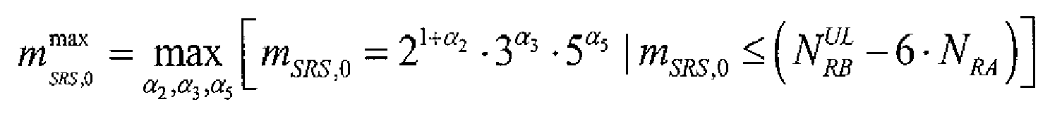
- N RB UL is the number of RBs to which the uplink system bandwidth corresponds
- N RA is the number of PRACHs in the UpPTS; ⁇ 2 , ⁇ 3 and ⁇ 5 are non-negative integers.
- This formula means that the maximum SRS-Bandwidth meeting m SRS , 0 ⁇ N RB UL - 6 ⁇ N RA can be
- the SRS-Bandwidth of each level of the tree structure is within the frequency band range of the maximum SRS-Bandwidth, and the relative position where the SR-bandwidth of each level is located in the maximum SRS-Bandwidth is changeable. Therefore, in order to prevent the SRS from interfering with the PRACH in the UpPTS and implement the channel sounding for more bandwidth, the frequency domain position of the maximum SRS-Bandwidth in the UpPTS should be configured reasonably.
- the technical problem to be solved in the present invention is to provide a method for sending an SRS of uplink channel in a TDD system.
- the sending position of the maximum SRS-Bandwidth in the UpPTS which is obtained by the method, the interference between the UpPTS signal and the PARCH can be avoided and it is possible to implement the channel sounding for more bandwidth.
- the present invention provides a method for sending an SRS of uplink channel in a TDD system
- a terminal calculates the parameters of the resource for sending an SRS in a UpPTS according to the configuration information related to the SRS of the uplink channel, the parameters include a frequency domain starting position of the resource, and then the SRS is sent over the resource; wherein it is necessary to determine an index of the first sub-carrier in the maximum SRS-Bandwidth when the frequency domain starting position of the resource is calculated; wherein the terminal determines the index according to the frequency domain position of one PRACH or that of more PRACHs in the UpPTS, when the PRACH includes the sub-carrier at the lower boundary of the system bandwidth, the upper boundary of the system bandwidth is used as the end position of the maximum SRS-Bandwidth, thereby the starting position of the maximum SRS-Bandwidth can be calculated; and when the PRACH includes the sub-carrier at the upper boundary of the system bandwidth, the lower boundary of the system bandwidth is used as the
- the present invention further provides a method for sending an SRS of uplink channel in a TDD system
- a terminal calculates the parameters of the resource for sending an SRS in a UpPTS according to the configuration information related to the SRS of the uplink channel, the parameters include a frequency domain starting position of the resource, and then the SRS is sent over the resource; wherein it is necessary to determine an index of the first sub-carrier in the maximum SRS-Bandwidth when the frequency domain starting position of the resource is calculated; wherein the terminal determines the index according to the frequency domain position of one PRACH or that of more PRACHs in the UpPTS, first the maximum SRS-Bandwidth is located in the middle of the remaining frequency band which is obtained through subtracting from the uplink system bandwidth the frequency band occupied by the PRACH, thereby the starting position of the maximum SRS-Bandwidth is calculated, and then the index can be determined through the starting position of the maximum SRS-Bandwidth plus the offset parameter configured for the terminal.
- the present invention further provides a method for sending an SRS of uplink channel in a TDD system
- the present invention further provides a method for sending an SRS of uplink channel in a TDD system
- a terminal calculates the parameters of the resource for sending an SRS in a UpPTS according to the configuration information related to the SRS of the uplink channel, the parameters include a frequency domain starting position of the resource, and then the SRS is sent over the resource; wherein it is necessary to determine an index of the first sub-carrier in the maximum SRS-Bandwidth when the frequency domain starting position of the resource is calculated; wherein the terminal determines the index according to the frequency domain position of one PRACH or that of more PRACHs in the UpPTS, when the PRACH includes the sub-carrier at the lower boundary of the system bandwidth, the first sub-carrier following the PRACH is used as the starting position of the maximum SRS-Bandwidth; and when the PRACH includes the sub-carrier at the upper boundary of the system bandwidth, the lower boundary of the system bandwidth is used as the starting position of the maximum SRS-Bandwidth, and then
- the present invention further provides a method for sending an SRS of uplink channel in a TDD system
- N RA may be the number of PRACHs in the UpPTS; ⁇ 2 , ⁇ 3 and ⁇ 5 may be non-negative integers;
- m SRS,0 may be the SRS-Bandwidth of the first level, which is recalculated through selecting ⁇ 2 , ⁇ 3 and ⁇ 5 ; m SRS may be the maximum SRS-Bandwidth, which is obtained through selecting ⁇ 2 , ⁇ 3
- the terminal may calculate the maximum SRS-Bandwidth m SRS by the first method or the second method, when the SRS-Bandwidth configured for the terminal is on the first level of the tree structure of SRS bandwidth configuration; and may calculate the maximum SRS-Bandwidth m SRS by the third method, when the SRS-Bandwidth configured for the terminal is not on the first level of the tree structure of SRS bandwidth configuration.
- the sending position of the maximum SRS-Bandwidth in the UpPTS which is obtained by the method of the present invention, the interference between the UpPTS signal and the PARCH can be avoided. Further, as the bandwidth used by the SRS has wider distribution in the frequency domain when the PRACH is in different positions, it is possible to implement the channel sounding for more bandwidth.
- the present invention takes an LTE system for example, but is not limited to the LTE system. It can also be used in other TDD systems.
- a terminal When a terminal (it is called a user equipment (UE) in an LTE system) is to send an SRS, it needs to calculate the parameters of the resource for sending the SRS in a UpPTS according to configuration information related to the SRS, the parameters include a frequency domain starting position of the resource, and then the SRS is sent over the resource; wherein it is necessary to determine an index of the first sub-carrier in the maximum SRS-Bandwidth, when the frequency domain starting position of the resource is calculated.
- UE user equipment
- the foregoing configuration information related to the SRS includes the configuration information related to the assigned resource (the assigned SRS-bandwidth is continuously distributed in the frequency domain) which is assigned by the base station for the SRS in the UpPTS and sent to the terminal by the base station when the base station needs to receive the SRS to perform the uplink channel sounding, such as the number of the level where the SRS-Bandwidth configured for the terminal is located in the corresponding tree structure.
- the calculated parameters of the resource for sending the SRS include parameters related to the time domain, frequency domain and the sequence used. What the present invention cares is the frequency domain starting position (i.e.
- the terminal can calculate the frequency domain starting position of the resource for sending the SRS.
- the specific algorithm can refer to the provisions in the standard.
- some cell-specific parameters can be acquired from the cell broadcast, UE-specific parameters are configured through high layer signaling, and some other parameters are acquired through calculation according to other parameters.
- the acquisition of these parameters can refer to related standards.
- the terminal determines the index according to the frequency domain position of one PRACH or that of more PRACHs in the UpPTS, when the PRACH is mapped from the low frequency band to the high frequency band in the system bandwidth (in this case, one or more PRACHs in the UpPTS as a whole should contain the sub-carrier at the lower boundary of the system bandwidth), the upper boundary of the system bandwidth (the sub-carrier with the highest frequency band) is used as the end position of the maximum SRS-Bandwidth, thereby the starting position of the maximum SRS-Bandwidth can be calculated; when the PRACH is mapped from the high frequency band to the low frequency band in the system bandwidth (in this case, one or more PRACHs in the UpPTS as an whole should contain the sub-carrier at the upper boundary of the system bandwidth), the lower boundary of the system bandwidth (the sub-carriers with the lowest frequency band) is used as the starting position of the maximum SRS-Bandwidth, and then the index of the first sub-carrier in the maximum SRS-
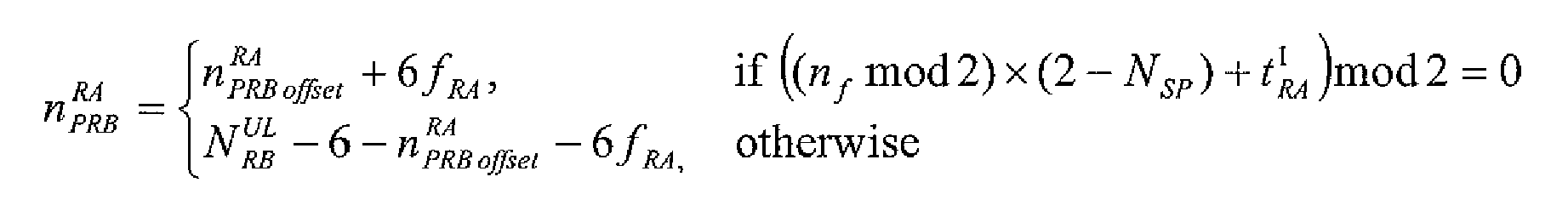
- n f is the system frame number of the radio frame where the UpPTS is located;
- any one of the foregoing three methods for calculating the maximum SRS-Bandwidth can be selected.
- This embodiment is basically the same as the first embodiment.
- the difference between the two embodiments is in the method by which the index of the first sub-carrier in the maximum SRS-Bandwidth is calculated.
- the terminal determines the index according to the frequency domain position of one PRACH or that of more PRACHs in the UpPTS, first the maximum SRS-Bandwidth is located in the middle of the remaining frequency band which is obtained through subtracting from the uplink system bandwidth the frequency band occupied by the PRACH, thereby the starting position of the maximum SRS-Bandwidth is calculated, and then the index can be determined through the starting position of the maximum SRS-Bandwidth plus the offset parameter configured for the terminal.
- the terminal can determine the foregoing maximum SRS-Bandwidth by the same methods as that of the first embodiment.
- This embodiment is basically the same as the first embodiment.
- the difference between the two embodiments is in the method by which the index of the first sub-carrier in the maximum SRS-Bandwidth is calculated.
- the terminal determines the index according to the frequency domain position of one PRACH or that of more PRACHs in the UpPTS, when the PRACH includes the sub-carrier at the lower boundary of the system bandwidth, the first sub-carrier following the PRACH is used as the starting position of the maximum SRS-Bandwidth; when the PRACH includes the sub-carriers at the upper boundary of the system bandwidth, the lower boundary of the system bandwidth is used as the starting position of the maximum SRS-Bandwidth, and then the index can be determined through the starting position of the maximum SRS-Bandwidth plus the offset parameter configured for the terminal.
- the terminal can determine the foregoing maximum SRS-Bandwidth by the same methods as that of the first embodiment.
- the starting position of the maximum SRS-Bandwidth is calculated by the method of the second embodiment: i.e. the maximum SRS-Bandwidth is located in the middle of the remaining frequency band which is obtained through subtracting from the uplink system bandwidth the frequency band occupied by the PRACH. when the PRACH is mapped from the high frequency band to the low frequency band in the system bandwidth (i.e.
- the starting position of the maximum SRS-Bandwidth is calculated by the method of the third embodiment.
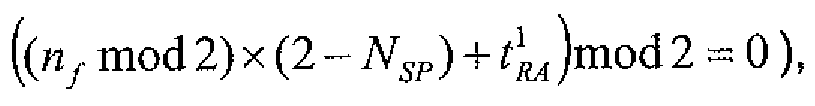
- the PRACH is mapped from the high frequency band to the low frequency band in the system bandwidth (i.e. when n f mod 2 ⁇ 2 - N SP + t RA 1 mod 2 ⁇ 0 )
- the starting position of the maximum SRS-Bandwidth is at the lower boundary of the system frequency band
- the PRACH is mapped from the low frequency band to the high frequency band in the system bandwidth (i.e.
- the present invention provides a method for sending an SRS of uplink channel in a TDD system. With sending position of the maximum SRS-Bandwidth in the UpPTS, which is obtained by the method of the present invention, the interference between the UpPTS signal and the PARCH can be avoided, and it is possible to implement the channel sounding for more bandwidth.
Landscapes
- Engineering & Computer Science (AREA)
- Signal Processing (AREA)
- Computer Networks & Wireless Communication (AREA)
- Mobile Radio Communication Systems (AREA)
- Bidirectional Digital Transmission (AREA)
- Time-Division Multiplex Systems (AREA)
Abstract
Description
- The present invention relates to a time division duplex (TDD) system, particularly to a method for sending a sounding reference signal (SRS) of uplink channel in a TDD system.
- A frame structure under a TDD mode in the Long Term Evolution (LTE) system (also called frame structure type 2) is shown in
Fig. 1 . In this frame structure, a radio frame of a length of 10ms (307200 Ts, 1ms = 30720 Ts) is divided into two half-frames, the length of each half-frame is 5ms (153600Ts), and each half-frame contains 5 subframes of a length of 1 ms each. The role of each subframe is shown in Table 1, wherein D denotes a downlink subframe used to transmit downlink signals; and U denotes an uplink subframe used to transmit uplink signals. Further, an uplink/downlink subframe is divided into two time slots of a length of 0.5ms each. S denotes a special subframe containing three special time slots which are a Downlink Pilot Time Slot (DwPTS), a Guard Period (GP) and an Uplink Pilot Time Slot (UpPTS). In a practical system, the mobile phones are informed of the indexes of uplink/downlink configuration through broadcast messages.Table 1 Uplink/Downlink configuration Configuration Switch-point periodicity Subframe number 0 1 2 3 4 5 6 7 8 9 0 5 ms D S U U U D S U U U 1 5 ms D S U U D D S U U D 2 5 ms D S U D D D S U D D 3 10 ms D S U U U D D D D D 4 10 ms D S U U D D D D D D 5 10 ms D S U D D D D D D D 6 5 ms D S U U U D S U U D - The structure of the Physical Random Access Channel (PRACH, also called Random Access Opportunity) in the LTE system is shown in
Fig. 2 . A preamble consists of a CP and a Sequence. Different preamble formats mean different lengths of CPs and/or Sequences. Currently, the preamble formats supported by the TDD mode in the LTE system are shown in Table 2.Table 2 Preamble formats Preamble format T CP T SEQ 0 3168·T s 24576· T s1 21024·T s 24576· T s2 6240·T s 2.24576· T s3 21024· T s2·24576·T s 4 ( frame structure type 2 only)448·T s 4096·T s - Among the foregoing preamble formats, preamble formats 0-3 are transmitted in the normal uplink subframes, while
preamble format 4 is transmitted in the UpPTS. -
Preamble format 0 is transmitted in one normal uplink subframe; -
Preamble format -
Preamble format 3 is transmitted in three normal uplink subframes; -
Preamble format 4 is transmitted in the UpPTS (the starting position for transmitting is the position which is 5158Ts before the end of UpPTS). - A Resource Block (RB) is used as a unit in the resource assignment in the LTE system. An RB occupies 12 Resource Elements (REs) in the frequency domain and occupies one time slot in the time domain, i.e. occupies 7 SC-OFDM symbols of normal cyclic prefix (normal CP) or 6 SC-OFDM symbols of extended cyclic prefix (extended CP). If the total number of RBs to which the uplink system bandwidth corresponds in the frequency domain is defined as


- In the frequency domain, a PRACH occupies the bandwidth to which 6 RBs correspond, i.e. 72 REs. The bandwidth of each RE is 15kHz. The PRACHs with the same time domain positions are differentiated by the frequency domain.
- An UpPTS in the TDD system may be used to send an SRS of uplink channel and a PRACH of
Preamble format 4. - The method of alternate one-side mapping is adopted in the frequency domain mapping of the PRACH sent in the UpPTS, i.e. mapping from the low frequency band to the high frequency band in certain UpPTS and mapping from the high frequency band to the low frequency band in a neighboring UpPTS. The mapping formula may be expressed in the following form.


- SRS-Bandwidth configuration is based on a tree structure. Each SRS bandwidth configuration corresponds to a tree structure, the SRS-Bandwidth of the highest level corresponds to the maximum bandwidth of this SRS bandwidth configuration. Tables 3-6 show the SRS bandwidth configurations in different uplink bandwidth ranges. m SRS,b denotes the number of RBs which correspond to the SRS-Bandwidth of the level whose index is b in the tree structure, Nb denotes the number of branch nodes of a node on the level whose index is (b -1), which are located on the level whose index is b in the tree structure, b=0 corresponds to the first level, namely the highest level of the tree structure, and m SRS,0 is the maximum SRS-Bandwidth under this configuration. N/A denotes that there are not any corresponding branch nodes on the level.
- Taking the
SRS bandwidth configuration 1 in Table 3 for example, b=0 is the first level, the SRS-Bandwidth to which this level corresponds is the bandwidth to which 32 RBs correspond, and is the maximum SRS-Bandwidth of this SRS bandwidth configuration; b=1 is the second level, the SRS-Bandwidth of this level is the bandwidth to which 16 RBs correspond, and the SRS-Bandwidth of the first level is divided into two SRS-Bandwidths of the second level; b=2 is the third level, the SRS-Bandwidth of this level is the bandwidth to which 8 RBs correspond, and the SRS-Bandwidth of the second level is divided into two SRS-Bandwidths of the third level; b=3 is the fourth level, the SRS-Bandwidth of this level is the bandwidth to which 4 RBs correspond, and the SRS-Bandwidth of the third level is divided into two SRS-Bandwidths of the fourth level. - Further, the sub-carriers of the SRS in the same SRS frequency band are located in every other sub-carrier. As shown in
Fig. 4 , this comb structure allows more users to send SRSs in the same SRS-Bandwidth. Table 3
SRS bandwidth configuration SRS-Bandwidth b = 0 SRS-Bandwidth b = 1 SRS-Bandwidth b = 2 SRS-Bandwidth b = 3 m SRS,b N b m SRS,b N b m SRS,b N b m SRS,b N b 0 36 1 12 3 N/ A 1 4 3 1 32 1 16 2 8 2 4 2 2 24 1 N/A 1 N/ A 1 4 6 3 20 1 N/A 1 N/ A 1 4 5 4 16 1 N/A 1 N/ A 1 4 4 5 12 1 N/A 1 N/ A 1 4 3 6 8 1 N/A 1 N/ A 1 4 2 7 4 1 N/A N/A N/A N/A N/A N/A - Table 4

SRS bandwidth configuration SRS-Bandwidth b = 0 SRS-Bandwidth b = 1 SRS-Bandwidth b = 2 SRS-Bandwidth b = 3 m SRS,b N b m SRS,b N b m SRS,b N b m SRS,b N b 0 48 1 24 2 12 2 4 3 1 48 1 16 3 8 2 4 2 2 40 1 20 2 N/ A 1 4 5 3 36 1 12 3 N/ A 1 4 3 4 32 1 16 2 8 2 4 2 5 24 1 N/A 1 N/ A 1 4 6 6 20 1 N/A 1 N/ A 1 4 5 7 16 1 N/A 1 N/A 1 4 4 - Table 5

SRS bandwidth configuration SRS-Bandwidth b = 0 SRS-Bandwidth b = 1 SRS-Bandwidth b = 2 SRS-Bandwidth b = 3 m SRS,b N b m SRS,b N b m SRS,b N b m SRS,b N b 0 72 1 24 3 12 2 4 3 1 64 1 32 2 16 2 4 4 2 60 1 20 3 N/ A 1 4 5 3 48 1 24 2 12 2 4 3 4 48 1 16 3 8 2 4 2 5 40 1 20 2 N/ A 1 4 5 6 36 1 12 3 N/A 1 4 3 7 32 1 16 2 8 2 4 2 - Table 6

SRS bandwidth configuration SRS-Bandwidth b = 0 SRS-Bandwidth b = 1 SRS-Bandwidth b = 2 SRS-Bandwidth b = 3 m SRS,b N b m SRS,b N b m SRS,b N b m SRS,b N b 0 96 1 48 2 24 2 4 6 1 96 1 32 3 16 2 4 4 2 80 1 40 2 20 2 4 5 3 72 1 24 3 12 2 4 3 4 64 1 32 2 16 2 4 4 5 60 1 20 3 N/ A 1 4 5 6 48 1 24 2 12 2 4 3 7 48 1 16 3 8 2 4 2 - In the UpPTS, when the maximum SRS-Bandwidth is used to send an SRS, the maximum SRS-Bandwidth


- When an SRS is sent, the SRS-Bandwidth of each level of the tree structure is within the frequency band range of the maximum SRS-Bandwidth, and the relative position where the SR-bandwidth of each level is located in the maximum SRS-Bandwidth is changeable. Therefore, in order to prevent the SRS from interfering with the PRACH in the UpPTS and implement the channel sounding for more bandwidth, the frequency domain position of the maximum SRS-Bandwidth in the UpPTS should be configured reasonably.
- The technical problem to be solved in the present invention is to provide a method for sending an SRS of uplink channel in a TDD system. With the sending position of the maximum SRS-Bandwidth in the UpPTS, which is obtained by the method, the interference between the UpPTS signal and the PARCH can be avoided and it is possible to implement the channel sounding for more bandwidth.
- To solve the foregoing technical problem, the present invention provides a method for sending an SRS of uplink channel in a TDD system, a terminal calculates the parameters of the resource for sending an SRS in a UpPTS according to the configuration information related to the SRS of the uplink channel, the parameters include a frequency domain starting position of the resource, and then the SRS is sent over the resource; wherein it is necessary to determine an index of the first sub-carrier in the maximum SRS-Bandwidth when the frequency domain starting position of the resource is calculated;
wherein the terminal determines the index according to the frequency domain position of one PRACH or that of more PRACHs in the UpPTS, when the PRACH includes the sub-carrier at the lower boundary of the system bandwidth, the upper boundary of the system bandwidth is used as the end position of the maximum SRS-Bandwidth, thereby the starting position of the maximum SRS-Bandwidth can be calculated; and when the PRACH includes the sub-carrier at the upper boundary of the system bandwidth, the lower boundary of the system bandwidth is used as the starting position of the maximum SRS-Bandwidth, and then the index can be determined through the starting position of the maximum SRS-Bandwidth plus the offset parameter configured for the terminal. - To solve the foregoing technical problem, the present invention also provides a method for sending an SRS of uplink channel in a TDD system, a terminal calculates the parameters of the resource for sending an SRS in a UpPTS according to the configuration information related to the SRS of the uplink channel, the parameters include a frequency domain starting position of the resource, and then the SRS is sent over the resource; wherein it is necessary to determine an index k 0 of the first sub-carrier in the maximum SRS-Bandwidth mSRS when the frequency domain starting position of the resource is calculated;
wherein the terminal calculates the index k 0 with the following formula:


- To solve the foregoing technical problem, the present invention further provides a method for sending an SRS of uplink channel in a TDD system, a terminal calculates the parameters of the resource for sending an SRS in a UpPTS according to the configuration information related to the SRS of the uplink channel, the parameters include a frequency domain starting position of the resource, and then the SRS is sent over the resource; wherein it is necessary to determine an index of the first sub-carrier in the maximum SRS-Bandwidth when the frequency domain starting position of the resource is calculated;
wherein the terminal determines the index according to the frequency domain position of one PRACH or that of more PRACHs in the UpPTS, first the maximum SRS-Bandwidth is located in the middle of the remaining frequency band which is obtained through subtracting from the uplink system bandwidth the frequency band occupied by the PRACH, thereby the starting position of the maximum SRS-Bandwidth is calculated, and then the index can be determined through the starting position of the maximum SRS-Bandwidth plus the offset parameter configured for the terminal. - To solve the foregoing technical problem, the present invention further provides a method for sending an SRS of uplink channel in a TDD system, a terminal calculates the parameters of the resource for sending an SRS in a UpPTS according to the configuration information related to the SRS of the uplink channel, the parameters include a frequency domain starting position of the resource, and then the SRS is sent over the resource; wherein it is necessary to determine an index k 0 of the first sub-carrier in the maximum SRS-Bandwidth mSRS when the frequency domain starting position of the resource is calculated;
wherein the terminal calculates the index k 0 with the following formula:
wherein


- To solve the foregoing technical problem, the present invention further provides a method for sending an SRS of uplink channel in a TDD system, a terminal calculates the parameters of the resource for sending an SRS in a UpPTS according to the configuration information related to the SRS of the uplink channel, the parameters include a frequency domain starting position of the resource, and then the SRS is sent over the resource; wherein it is necessary to determine an index of the first sub-carrier in the maximum SRS-Bandwidth when the frequency domain starting position of the resource is calculated;
wherein the terminal determines the index according to the frequency domain position of one PRACH or that of more PRACHs in the UpPTS, when the PRACH includes the sub-carrier at the lower boundary of the system bandwidth, the first sub-carrier following the PRACH is used as the starting position of the maximum SRS-Bandwidth; and when the PRACH includes the sub-carrier at the upper boundary of the system bandwidth, the lower boundary of the system bandwidth is used as the starting position of the maximum SRS-Bandwidth, and then the index can be determined through the starting position of the maximum SRS-Bandwidth plus the offset parameter configured for the terminal. - To solve the foregoing technical problem, the present invention further provides a method for sending an SRS of uplink channel in a TDD system, a terminal calculates the parameters of the resource for sending an SRS in a UpPTS according to the configuration information related to the SRS of the uplink channel, the parameters include a frequency domain starting position of the resource, and then the SRS is sent over the resource; wherein it is necessary to determine an index k 0 of the first sub-carrier in the maximum SRS-Bandwidth mSRS when the frequency domain starting position of the resource is calculated;
wherein the terminal calculates the index k 0 with the following formula:


- Further, among the foregoing sending methods, the terminal may calculate the maximum SRS-Bandwidth mSRS by one of the following three methods:
the first method: the terminal may calculate the maximum SRS-Bandwidth mSRS with the following formula:

the second method: the terminal may calculate the maximum SRS-Bandwidth mSRS with the formula
the third method: the terminal may use the SRS-Bandwidth mSRS ,0 of the first level in the tree structure to which SRS bandwidth configuration corresponds as the maximum SRS-Bandwidth mSRS . - Further, the terminal may calculate the maximum SRS-Bandwidth mSRS by the first method or the second method, when the SRS-Bandwidth configured for the terminal is on the first level of the tree structure of SRS bandwidth configuration; and may calculate the maximum SRS-Bandwidth mSRS by the third method, when the SRS-Bandwidth configured for the terminal is not on the first level of the tree structure of SRS bandwidth configuration.
- With the sending position of the maximum SRS-Bandwidth in the UpPTS, which is obtained by the method of the present invention, the interference between the UpPTS signal and the PARCH can be avoided. Further, as the bandwidth used by the SRS has wider distribution in the frequency domain when the PRACH is in different positions, it is possible to implement the channel sounding for more bandwidth.
- The drawings are intended to provide further understanding of the present invention and constitute a part of the application. The illustrative embodiments of the present invention and their descriptions are intended to explain the present invention and not to limit the present invention. Among the drawings:
-
Fig. 1 is a schematic diagram of a frame structure under a TDD mode in the LTE system; -
Fig. 2 is a schematic diagram of a PRACH structure; -
Fig. 3 is a schematic diagram of a tree structure of SRS-Bandwidth; -
Fig. 4 is a schematic diagram of a comb structure of an SRS; -
Fig. 5A andFig. 5B are respectively a schematic diagram of the starting position of the maximum SRS-Bandwidth with the PRACH mapped from the high frequency band to the low frequency band in the system bandwidth, and that of the maximum SRS-Bandwidth with the PRACH mapped from the low frequency band to the high frequency band according to the application example 1 of the present invention; -
Fig. 6A and Fig. 6B are respectively a schematic diagram of the starting position of the maximum SRS-Bandwidth with the PRACH mapped from the high frequency band to the low frequency band in the system bandwidth, and that of the maximum SRS-Bandwidth with the PRACH mapped from the low frequency band to the high frequency band according to the application example 2 of the present invention; -
Fig. 7A and Fig. 7B are respectively a schematic diagram of the starting position of the maximum SRS-Bandwidth with the PRACH mapped from the high frequency band to the low frequency band in the system bandwidth, and that of the maximum SRS-Bandwidth with the PRACH mapped from the low frequency band to the high frequency band according to the application example 3 of the present invention; -
Fig. 8A andFig. 8B are respectively a schematic diagram of the starting position of the maximum SRS-Bandwidth with the PRACH mapped from the high frequency band to the low frequency band in the system bandwidth, and that of the maximum SRS-Bandwidth with the PRACH mapped from the low frequency band to the high frequency band according to the application example 4 of the present invention; -
Fig. 9A and Fig. 9B are respectively a schematic diagram of the starting position of the maximum SRS-Bandwidth with the PRACH mapped from the high frequency band to the low frequency band in the system bandwidth, and that of the maximum SRS-Bandwidth with the PRACH mapped from the low frequency band to the high frequency band according to the application example 5 of the present invention; - In
Fig. 4 and the subsequent drawings,stands for the zone of the sub-carriers used by the terminal in the SRS-Bandwidth when kTC =1; and stands for the zone of the sub-carriers used by the terminal in the SRS-Bandwidth when kTC = 0.
- In the following description, the present invention is described in detail in combination with the drawings and embodiments of the present invention. The present invention takes an LTE system for example, but is not limited to the LTE system. It can also be used in other TDD systems.
- When a terminal (it is called a user equipment (UE) in an LTE system) is to send an SRS, it needs to calculate the parameters of the resource for sending the SRS in a UpPTS according to configuration information related to the SRS, the parameters include a frequency domain starting position of the resource, and then the SRS is sent over the resource; wherein it is necessary to determine an index of the first sub-carrier in the maximum SRS-Bandwidth, when the frequency domain starting position of the resource is calculated.
- The foregoing configuration information related to the SRS includes the configuration information related to the assigned resource (the assigned SRS-bandwidth is continuously distributed in the frequency domain) which is assigned by the base station for the SRS in the UpPTS and sent to the terminal by the base station when the base station needs to receive the SRS to perform the uplink channel sounding, such as the number of the level where the SRS-Bandwidth configured for the terminal is located in the corresponding tree structure. After the terminal receives the configuration information related to the SRS, the calculated parameters of the resource for sending the SRS include parameters related to the time domain, frequency domain and the sequence used. What the present invention cares is the frequency domain starting position (i.e. its index) of the first sub-carrier in the maximum SRS-Bandwidth among the frequency domain parameters, because the SRS-Bandwidth assigned by the base station on each level of the tree structure is within the frequency band range of the maximum SRS-Bandwidth, and the relative position of the SRS-Bandwidth on each level, which is located in the maximum SRS-Bandwidth can be determined according to the corresponding configuration parameters obtained by the terminal. Therefore, according to the index of the first sub-carrier in the maximum SRS-Bandwidth, the terminal can calculate the frequency domain starting position of the resource for sending the SRS. The specific algorithm can refer to the provisions in the standard.
- In addition, it should be noted that among the parameters in the calculation formulae used in the present invention, some cell-specific parameters can be acquired from the cell broadcast, UE-specific parameters are configured through high layer signaling, and some other parameters are acquired through calculation according to other parameters. The acquisition of these parameters can refer to related standards.
- In this embodiment, the terminal determines the index according to the frequency domain position of one PRACH or that of more PRACHs in the UpPTS, when the PRACH is mapped from the low frequency band to the high frequency band in the system bandwidth (in this case, one or more PRACHs in the UpPTS as a whole should contain the sub-carrier at the lower boundary of the system bandwidth), the upper boundary of the system bandwidth (the sub-carrier with the highest frequency band) is used as the end position of the maximum SRS-Bandwidth, thereby the starting position of the maximum SRS-Bandwidth can be calculated; when the PRACH is mapped from the high frequency band to the low frequency band in the system bandwidth (in this case, one or more PRACHs in the UpPTS as an whole should contain the sub-carrier at the upper boundary of the system bandwidth), the lower boundary of the system bandwidth (the sub-carriers with the lowest frequency band) is used as the starting position of the maximum SRS-Bandwidth, and then the index of the first sub-carrier in the maximum SRS-Bandwidth can be determined through the starting position of the maximum SRS-Bandwidth plus the offset parameter configured for the terminal.
- The formula, with which the terminal calculates the index k 0 of the first sub-carrier (i.e. the sub-carrier with the minimum index) in the maximum SRS-Bandwidth, is as follows:


- Besides, "otherwise" in the formula denotes the circumstance of

in this embodiment, the terminal calculates the maximum SRS-Bandwidth mSRS with the following formula, when the SRS bandwidth configured for the terminal is on the first level of the tree structure of SRS bandwidth configuration:

Or the maximum SRS-Bandwidth can also be calculated with the formula
- In another embodiment, any one of the foregoing three methods for calculating the maximum SRS-Bandwidth can be selected.
- This embodiment is basically the same as the first embodiment. The difference between the two embodiments is in the method by which the index of the first sub-carrier in the maximum SRS-Bandwidth is calculated. In this embodiment, when the terminal determines the index according to the frequency domain position of one PRACH or that of more PRACHs in the UpPTS, first the maximum SRS-Bandwidth is located in the middle of the remaining frequency band which is obtained through subtracting from the uplink system bandwidth the frequency band occupied by the PRACH, thereby the starting position of the maximum SRS-Bandwidth is calculated, and then the index can be determined through the starting position of the maximum SRS-Bandwidth plus the offset parameter configured for the terminal.
- The formula, with which the terminal calculates the index k 0 of the first sub-carrier in the maximum SRS-Bandwidth, is as follows:


- The terminal can determine the foregoing maximum SRS-Bandwidth by the same methods as that of the first embodiment.
- This embodiment is basically the same as the first embodiment. The difference between the two embodiments is in the method by which the index of the first sub-carrier in the maximum SRS-Bandwidth is calculated. In this embodiment, the terminal determines the index according to the frequency domain position of one PRACH or that of more PRACHs in the UpPTS, when the PRACH includes the sub-carrier at the lower boundary of the system bandwidth, the first sub-carrier following the PRACH is used as the starting position of the maximum SRS-Bandwidth; when the PRACH includes the sub-carriers at the upper boundary of the system bandwidth, the lower boundary of the system bandwidth is used as the starting position of the maximum SRS-Bandwidth, and then the index can be determined through the starting position of the maximum SRS-Bandwidth plus the offset parameter configured for the terminal.
- The formula, with which the terminal calculates the index k 0 of the first sub-carrier in the maximum SRS-Bandwidth, is as follows:


- The terminal can determine the foregoing maximum SRS-Bandwidth by the same methods as that of the first embodiment.
- In the following, the methods of the present invention are described in combination with application examples.
- Condition:
- the number of RBs to which the uplink system bandwidth corresponds is

- the uplink/downlink time slot configuration adopted by the TDD system is
Configuration 1, then the number of the switch-points from downlink to uplink in a radio frame is NSP = 2 ; - the number of PRACHs in an UpPTS is NRA =1;
- the formula
- kTC = 0.
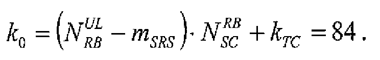
- Here the starting position of the maximum SRS-Bandwidth is calculated by the method of the first embodiment:
- when the PRACH is mapped from the high frequency band to the low frequency band in the system bandwidth (i.e. when

- when the PRACH is mapped from the low frequency band to the high frequency band in the system bandwidth (i.e. when

- The positions of the maximum SRS-Bandwidth under the foregoing two circumstances are shown in
Fig. 5A andFig. 5B respectively. - Condition:
- the number of RBs to which the uplink system bandwidth corresponds is

- the uplink/downlink time slot configuration adopted by the TDD system is
Configuration 1, then the number of the switch-points from downlink to uplink in a radio frame is NSP = 2; - the number of PRACHs in an UpPTS is NRA =1;
-
SRS bandwidth configuration 4 is adopted, from Table 1, it is got that the maximum SRS-Bandwidth mSRS = m SRS,0 = 16;
- Here the starting position of the maximum SRS-Bandwidth is calculated by the method of the first embodiment:
- when the PRACH is mapped from the high frequency band to the low frequency band in the system bandwidth (i.e. when

- when the PRACH is mapped from the low frequency band to the high frequency band in the system bandwidth (i.e. when


- The positions of the maximum SRS-Bandwidth under the foregoing two circumstances are shown in
Fig. 6A and Fig. 6B respectively. - Condition:
- the number of RBs to which the uplink system bandwidth corresponds is

- the uplink/downlink time slot configuration adopted by the TDD system is
Configuration 1, then the number of the switch-points from downlink to uplink in a radio frame is NSP = 2 ; - the number of PRACHs in an UpPTS is NRA =1;
-
SRS bandwidth configuration 4 is adopted, from Table 1, it is got that the maximum SRS-Bandwidth mSRS = m SRS,0 =16;
- Here the starting position of the maximum SRS-Bandwidth is calculated by the method of the second embodiment: i.e. the maximum SRS-Bandwidth is located in the middle of the remaining frequency band which is obtained through subtracting from the uplink system bandwidth the frequency band occupied by the PRACH.
when the PRACH is mapped from the high frequency band to the low frequency band in the system bandwidth (i.e. when

when the PRACH is mapped from the low frequency band to the high frequency band in the system bandwidth (i.e. when
SRS-Bandwidth is
- The positions of the maximum SRS-Bandwidth under the foregoing two circumstances are shown in
Fig. 7A and Fig. 7B respectively. - Condition:
- the number of RBs to which the uplink system bandwidth corresponds is

- the uplink/downlink time slot configuration adopted by the TDD system is
Configuration 1, then the number of the switch-points from downlink to uplink in a radio frame is NSP = 2. - the number of PRACHs in an UpPTS is MRA = 1;
-
SRS bandwidth configuration 4 is adopted, from Table 1, it is got that maximum SRS-Bandwidth is mSRS = m SRS,0 =16.
- Here the starting position of the maximum SRS-Bandwidth is calculated by the method of the third embodiment.
when the PRACH is mapped from the high frequency band to the low frequency band in the system bandwidth (i.e. when
when the PRACH is mapped from the low frequency band to the high frequency band in the system bandwidth (i.e. when

- The positions of the maximum SRS-Bandwidth under the foregoing two circumstances are shown in
Fig. 8A andFig. 8B respectively. - Condition:
- the number of RBs to which the uplink system bandwidth corresponds is
the uplink/downlink time slot configuration adopted by the TDD system isConfiguration 1, then the number of the switch-points from downlink to uplink in a radio frame is NSP = 2. - the number of PRACHs in an UpPTS is NRA =1;
- the formula

bandwidth mSRS =19.
- Here the starting position of the maximum SRS-Bandwidth is calculated by the method of the first embodiment:
- when the PRACH is mapped from the high frequency band to the low frequency band in the system bandwidth (i.e. when
- when the PRACH is mapped from the low frequency band to the high frequency band in the system bandwidth (i.e. when

- The positions of the maximum SRS-Bandwidth under the foregoing two circumstances are shown in
Fig. 9A and Fig. 9B respectively. - The foregoing descriptions are only preferred embodiments of the present invention and are not intended to limit the present invention. For those skilled in the art, the present invention may have various changes and modifications. All modifications, equivalent substitutions and improvements etc, made without departing from the spirit and principle of the present invention shall be within the protection scope of the present invention.
- The present invention provides a method for sending an SRS of uplink channel in a TDD system. With sending position of the maximum SRS-Bandwidth in the UpPTS, which is obtained by the method of the present invention, the interference between the UpPTS signal and the PARCH can be avoided, and it is possible to implement the channel sounding for more bandwidth.
Claims (12)
- A method for sending an SRS of uplink channel in a TDD system, a terminal calculating the parameters of the resource for sending an SRS in a UpPTS according to the configuration information related to the SRS of the uplink channel, the parameters including a frequency domain starting position of the resource, and then the SRS being sent over the resource; wherein it being necessary to determine an index of the first sub-carrier in the maximum SRS-Bandwidth when the frequency domain starting position of the resource is calculated;
the terminal determining the index according to the frequency domain position of one PRACH or that of more PRACHs in the UpPTS, when the PRACH includes the sub-carrier at the lower boundary of the system bandwidth, the upper boundary of the system bandwidth being used as the end position of the maximum SRS-Bandwidth, thereby the starting position of the maximum SRS-Bandwidth being calculated; and when the PRACH includes the sub-carrier at the upper boundary of the system bandwidth, the lower boundary of the system bandwidth being used as the starting position of the maximum SRS-Bandwidth, and then the index being determined through the starting position of the maximum SRS-Bandwidth plus the offset parameter configured for the terminal. - A method for sending an SRS of uplink channel in a TDD system, a terminal calculating the parameters of the resource for sending an SRS in a UpPTS according to the configuration information related to the SRS of the uplink channel, the parameters including a frequency domain starting position of the resource, and then the SRS being sent over the resource; wherein it being necessary to determine an index k 0 of the first sub-carrier in the maximum SRS-Bandwidth mSRS when the starting position of the resource is calculated;
the terminal calculating the index k 0 with the following formula: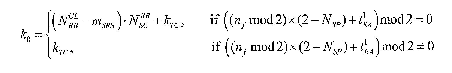
wherein


- The method according to claim 2, wherein the terminal calculates the maximum SRS-Bandwidth mSRS by one of the following three methods:the first method: the terminal calculates the maximum SRS-Bandwidth mSRS with the following formula:

wherein NRA is the number of PRACHs in the UpPTS; α2, α3 and α5 are non-negative integers; m SRS,0 is the SRS-Bandwidth of the first level, which is recalculated through selecting α2, α3 and α5 ; mSRS is the maximum SRS-Bandwidth, which is obtained through selecting a2 , α3 and α5 under the condition that
the second method: the terminal calculates the maximum SRS-Bandwidth mSRS with the formula
the third method: the terminal uses the SRS-Bandwidth m SRS,0 of the first level in the tree structure to which SRS bandwidth configuration corresponds as the maximum SRS-Bandwidth mSRS. - The method according to claim 3, wherein the terminal calculates the maximum SRS-Bandwidth mSRS by the first method or the second method, when the SRS-Bandwidth configured for the terminal is on the first level of the tree structure of SRS bandwidth configuration; and calculates the maximum SRS-Bandwidth mSRS by the third method, when the SRS-Bandwidth configured for the terminal is not on the first level of the tree structure of SRS bandwidth configuration.
- A method for sending an SRS of uplink channel in a TDD system, a terminal calculating the parameters of the resource for sending an SRS in a UpPTS according to the configuration information related to the SRS of the uplink channel, the parameters including a frequency domain starting position of the resource, and then the SRS being sent over the resource; wherein it being necessary to determine an index of the first sub-carrier in the maximum SRS-Bandwidth when the frequency domain starting position of the resource is calculated;
the terminal determining the index according to the frequency domain position of one PRACH or that of more PRACHs in the UpPTS, first the maximum SRS-Bandwidth being located in the middle of the remaining frequency band which is obtained through subtracting from the uplink system bandwidth the frequency band occupied by the PRACH, thereby the starting position of the maximum SRS-Bandwidth being calculated, and then the index being determined through the starting position of the maximum SRS-Bandwidth plus the offset parameter configured for the terminal. - A method for sending an SRS of uplink channel in a TDD system, a terminal calculating the parameters of the resource for sending an SRS in a UpPTS according to the configuration information related to the SRS of the uplink channel, the parameters including a frequency domain starting position of the resource, and then the SRS being sent over the resource; wherein it being necessary to determine an index k 0 of the first sub-carrier in the maximum SRS-Bandwidth mSRS when the frequency domain starting position of the resource is calculated;
the terminal calculating the index k 0 with the following formula:
wherein


- The method according to claim 6, wherein the terminal calculates the maximum SRS-Bandwidth mSRS by one of the following three methods:the first method: the terminal calculates the maximum SRS-Bandwidth mSRS with the following formula:

wherein NRA is the number of PRACHs in the UpPTS; α2, α3 and α5 are non-negative integers; m SRS,0 is the SRS-Bandwidth of the first level, which is recalculated through selecting α2, α3 and α5 ; mSRS is the maximum SRS-Bandwidth, which is obtained through selecting α2, α3 and α5 under the condition that
the second method: the terminal calculates the maximum SRS-Bandwidth mSRS with the formula
the third method: the terminal uses the SRS-Bandwidth m SRS,0 of the first level in the tree structure to which SRS-Bandwidth configuration corresponds as the maximum SRS-Bandwidth mSRS. - The method according to claim 7, wherein the terminal calculates the maximum SRS-Bandwidth mSRS by the first method or the second method, when the SRS-Bandwidth configured for the terminal is on the first level of the tree structure of SRS bandwidth configuration; and calculates the maximum SRS-Bandwidth mSRS by the third method, when the SRS-Bandwidth configured for the terminal is not on the first level of the tree structure of SRS bandwidth configuration.
- A method for sending an SRS of uplink channel in a TDD system, a terminal calculating the parameters of the resource for sending an SRS in a UpPTS according to the configuration information related to the SRS of the uplink channel, the parameters including a frequency domain starting position of the resource, and then the SRS being sent over the resource; wherein it being necessary to determine an index of the first sub-carrier in the maximum SRS-Bandwidth when the frequency domain starting position of the resource is calculated;
the terminal determining the index according to the frequency domain position of one PRACH or that of more PRACHs in the UpPTS, when the PRACH includes the sub-carrier at the lower boundary of the system bandwidth, the first sub-carrier following the PRACH being used as the starting position of the maximum SRS-Bandwidth; and when the PRACH includes the sub-carriers at the upper boundary of the system bandwidth, the lower boundary of the system bandwidth being used as the starting position of the maximum SRS-Bandwidth, and then the index can be determined through the starting position of the maximum SRS-Bandwidth plus the offset parameter configured for the terminal. - A method for sending an SRS of uplink channel in a TDD system, a terminal calculating the parameters of the resource for sending an SRS in a UpPTS according to the configuration information related to the SRS of the uplink channel, the parameters including a frequency domain starting position of the resource, and then the SRS being sent over the resource; wherein it being necessary to determine an index k 0 of the first sub-carrier in the maximum SRS-Bandwidth mSRS when the frequency domain starting position of the resource is calculated;
the terminal calculates the index k 0 with the following formula:
wherein NRA being the number of PRACHs in the UpPTS;

- The method according to claim 10, wherein the terminal calculates the maximum SRS-Bandwidth mSRS by one of the following three methods:the first method: the terminal calculates the maximum SRS-Bandwidth mSRS with the following formula:

wherein NRA is the number of PRACHs in the UpPTS; α2, α3 and α5 are non-negative integers; m SRS,0 is the SRS-Bandwidth of the first level, which is recalculated through selecting α 2 , α3 and α5 ; mSRS is the maximum SRS-Bandwidth, which is obtained through selecting α2, α3 and α5 under the condition that
the second method: the terminal calculates the maximum SRS-Bandwidth mSRS with the formula
the third method: the terminal uses the SRS-Bandwidth m SRS,0 of the first level in the tree structure to which SRS bandwidth configuration corresponds as the maximum SRS-Bandwidth mSRS. - The method according to claim 11, wherein the terminal calculates the maximum SRS-Bandwidth mSRS by the first method or the second method, when the SRS-Bandwidth configured for the terminal is on the first level of the tree structure of SRS bandwidth configuration; and calculates the maximum SRS-Bandwidth mSRS by the third method, when the SRS-Bandwidth configured for the terminal is not on the first level of the tree structure of SRS bandwidth configuration.
Applications Claiming Priority (2)
| Application Number | Priority Date | Filing Date | Title |
|---|---|---|---|
| CN2008101353927A CN101335969B (en) | 2008-08-01 | 2008-08-01 | Transmission method of TDD system uplink channel measurement reference signal |
| PCT/CN2009/072100 WO2010012178A1 (en) | 2008-08-01 | 2009-06-02 | A method for sending sounding reference signal of uplink channel in time division duplex system |
Publications (3)
| Publication Number | Publication Date |
|---|---|
| EP2239989A1 true EP2239989A1 (en) | 2010-10-13 |
| EP2239989A4 EP2239989A4 (en) | 2013-05-08 |
| EP2239989B1 EP2239989B1 (en) | 2015-01-21 |
Family
ID=40198212
Family Applications (1)
| Application Number | Title | Priority Date | Filing Date |
|---|---|---|---|
| EP09802371.6A Active EP2239989B1 (en) | 2008-08-01 | 2009-06-02 | Uplink Channel Sounding Reference Signal Transmission in a Time Division Duplex System |
Country Status (8)
| Country | Link |
|---|---|
| US (1) | US8537729B2 (en) |
| EP (1) | EP2239989B1 (en) |
| JP (1) | JP5159945B2 (en) |
| CN (2) | CN101335969B (en) |
| BR (1) | BRPI0916379B1 (en) |
| ES (1) | ES2531401T3 (en) |
| RU (1) | RU2444157C1 (en) |
| WO (1) | WO2010012178A1 (en) |
Cited By (5)
| Publication number | Priority date | Publication date | Assignee | Title |
|---|---|---|---|---|
| WO2009088206A2 (en) | 2008-01-07 | 2009-07-16 | Samsung Electronics Co., Ltd. | Device and method for transmitting random access preamble |
| EP2276308A1 (en) * | 2008-03-26 | 2011-01-19 | ZTE Corporation | Method for mapping physical random access channels |
| EP2764749A1 (en) * | 2011-10-08 | 2014-08-13 | Huawei Technologies Co., Ltd. | Sounding reference signal transmission |
| WO2020198013A1 (en) * | 2019-03-22 | 2020-10-01 | Apple Inc. | Reservation signal to avoid the gap for pusch transmission in the mf-lite system |
| EP4106428A4 (en) * | 2020-02-13 | 2023-11-15 | Ntt Docomo, Inc. | Terminal and base station |
Families Citing this family (43)
| Publication number | Priority date | Publication date | Assignee | Title |
|---|---|---|---|---|
| CN101267679B (en) * | 2008-04-26 | 2013-03-27 | 中兴通讯股份有限公司 | A method for mapping physical random access channel |
| CN101335969B (en) * | 2008-08-01 | 2012-11-28 | 中兴通讯股份有限公司 | Transmission method of TDD system uplink channel measurement reference signal |
| US8825100B2 (en) * | 2008-08-11 | 2014-09-02 | Blackberry Limited | Method and system for providing a power boost for a wireless communication link using a subset of subcarrier frequencies of the wireless communication link channel as a reduced bandwidth channel |
| CN101651469B (en) * | 2008-08-15 | 2013-07-24 | 三星电子株式会社 | Frequency hopping method for sending uplink monitoring reference mark in LET system |
| CN101771463B (en) * | 2009-01-05 | 2012-12-12 | 电信科学技术研究院 | Method, device and system for sending uplink sounding reference signal |
| CN101772031B (en) * | 2009-01-06 | 2013-06-12 | 电信科学技术研究院 | Method and device for allocating sounding reference signal transmission resources |
| CN103037521B (en) * | 2009-01-19 | 2015-05-20 | 鼎桥通信技术有限公司 | Up-going reference mark signal realizing method in time division synchronization code division multiple access (TD-SCDMA) system |
| CN101478340B (en) * | 2009-01-21 | 2014-08-20 | 中兴通讯股份有限公司 | Method for sending measurement reference signal in uplink pilot timeslot of time division duplexing system |
| KR101635883B1 (en) | 2009-02-03 | 2016-07-20 | 엘지전자 주식회사 | Technique for Transmitting and Receiving Downlink Reference Signals |
| CN101500264B (en) * | 2009-02-06 | 2014-03-19 | 中兴通讯股份有限公司 | Method for determining uplink channel measurement reference signal bandwidth |
| CN101848538B (en) * | 2009-03-26 | 2012-11-21 | 电信科学技术研究院 | Method and equipment for determining SRS transmission bandwidth |
| CN101873646B (en) * | 2009-04-27 | 2012-12-26 | 电信科学技术研究院 | Measurement gap configuration method and device of multi-carrier polymerization system |
| US8964621B2 (en) * | 2009-05-08 | 2015-02-24 | Qualcomm Incorporated | Transmission and reception of a reference signal supporting positioning in a wireless communication network |
| KR101294815B1 (en) | 2009-05-15 | 2013-08-08 | 엘지전자 주식회사 | Method for transmitting sounding reference signal in wireless communication system and apparatus therefor |
| CN101594336B (en) * | 2009-06-19 | 2012-12-19 | 中兴通讯股份有限公司 | Method for sending positioning reference signals |
| CA2774806C (en) | 2009-09-21 | 2015-05-19 | Lg Electronics Inc. | Method for transmitting a sounding reference signal in a wireless communication system, and apparatus for same |
| CN101827444B (en) | 2010-03-31 | 2015-03-25 | 中兴通讯股份有限公司 | Signaling configuration system and method for measuring reference signal |
| JP5547572B2 (en) * | 2010-07-09 | 2014-07-16 | 京セラ株式会社 | Radio base station and radio communication method |
| JP5583512B2 (en) * | 2010-08-06 | 2014-09-03 | 京セラ株式会社 | Radio base station and radio communication method |
| CN102404074B (en) * | 2010-09-17 | 2014-06-18 | 电信科学技术研究院 | Transmission method and equipment of non-periodic SRS (Stimulated Raman scattering) in TDD (Time Division Duplexing) system |
| CN102469607B (en) * | 2010-11-09 | 2014-01-22 | 上海贝尔股份有限公司 | Methods and equipment for triggering and transmitting uplink sounding reference signal (SRS) |
| EP3313017B1 (en) * | 2011-03-24 | 2019-02-20 | LG Electronics Inc. -1- | Method for transmitting/receiving signal and device therefor |
| CN102761968B (en) * | 2011-04-27 | 2017-03-01 | 艾利森电话股份有限公司 | The detection reference signal uplink resource allocating method of multi-user installation and base station |
| CN102811494B (en) * | 2011-05-31 | 2015-09-09 | 华为技术有限公司 | A kind of data transmission method and device |
| CN102811191B (en) * | 2011-05-31 | 2016-06-08 | 华为技术有限公司 | A kind of data transmission method and device |
| CN102843670B (en) * | 2012-08-15 | 2014-10-15 | 大唐移动通信设备有限公司 | Method and device for locating supplemental restraint system (SRS) data exception |
| KR20140032545A (en) * | 2012-08-31 | 2014-03-17 | 삼성전자주식회사 | Method and apparatus for sounding in wireless communication system with dynamic change of uplink control channel resources |
| CN104519576A (en) | 2013-09-27 | 2015-04-15 | 北京三星通信技术研究有限公司 | Mobile terminal and data transmission method in wireless community |
| DK3758431T3 (en) * | 2014-03-25 | 2023-02-27 | Ericsson Telefon Ab L M | Improved PRACH preamble format |
| CN109587809B (en) * | 2014-03-27 | 2021-11-12 | 海德威无线科技有限公司 | Method and device for aperiodic SRS |
| JP6362707B2 (en) * | 2015-04-10 | 2018-07-25 | エルジー エレクトロニクス インコーポレイティド | Method and apparatus for transmitting or receiving a sounding reference signal in a wireless communication system |
| CN106685616B (en) | 2015-11-06 | 2020-10-13 | 中兴通讯股份有限公司 | Sending method and device of Sounding Reference Signal (SRS) |
| WO2018201295A1 (en) * | 2017-05-02 | 2018-11-08 | Oppo广东移动通信有限公司 | Method for transmitting signal, network device and terminal device |
| CN109150439B (en) * | 2017-06-16 | 2021-02-05 | 电信科学技术研究院 | Data transmission method, device, network side equipment and user equipment |
| CN107911203B (en) * | 2017-08-11 | 2023-11-14 | 华为技术有限公司 | Method, network device, terminal device and system for transmitting and receiving reference signal |
| CN109475003B (en) * | 2017-09-08 | 2024-03-29 | 华为技术有限公司 | Signal sending and receiving method and device |
| CN113225170A (en) * | 2017-09-30 | 2021-08-06 | 中兴通讯股份有限公司 | Wireless communication method and device |
| CN113660188A (en) | 2017-11-17 | 2021-11-16 | 华为技术有限公司 | Method and device for transmitting Sounding Reference Signal (SRS) |
| CN110831238B (en) * | 2018-08-09 | 2022-12-30 | 中兴通讯股份有限公司 | Data sending method, resource obtaining method and device |
| CN110830214B (en) | 2018-08-10 | 2021-02-05 | 华为技术有限公司 | Method and apparatus for transmitting SRS |
| CN112165373B (en) * | 2020-09-03 | 2022-07-29 | 国网江西省电力有限公司经济技术研究院 | Power distribution MIMO power line communication multi-terminal transmission method |
| CN114915529A (en) * | 2021-02-09 | 2022-08-16 | 维沃移动通信有限公司 | Resource determination method, information determination method, device and communication equipment |
| EP4295628A4 (en) * | 2021-03-22 | 2024-07-24 | Zte Corp | Systems and methods for sounding reference signal transmission |
Family Cites Families (8)
| Publication number | Priority date | Publication date | Assignee | Title |
|---|---|---|---|---|
| RU2320012C2 (en) | 2006-05-16 | 2008-03-20 | Владимир Анатольевич Ефремов | Method for transferring messages using check communication, method for active reduction of noises |
| US8417248B2 (en) * | 2006-08-14 | 2013-04-09 | Texas Instruments Incorporated | Methods and apparatus to schedule uplink transmissions in wireless communication systems |
| CN101106395A (en) * | 2007-08-15 | 2008-01-16 | 中兴通讯股份有限公司 | Method for controlling signaling and measuring pilot frequency |
| US8780790B2 (en) * | 2008-01-07 | 2014-07-15 | Qualcomm Incorporated | TDD operation in wireless communication systems |
| CN101615928B (en) * | 2008-06-25 | 2016-05-18 | 三星电子株式会社 | The method and apparatus of transmitting SRS signaling in LTE system |
| CN101335969B (en) * | 2008-08-01 | 2012-11-28 | 中兴通讯股份有限公司 | Transmission method of TDD system uplink channel measurement reference signal |
| US8320267B2 (en) * | 2009-06-23 | 2012-11-27 | Motorola Mobility Llc | Reference signal sounding for uplink pilot time slot in wireless communication system |
| KR101733489B1 (en) * | 2010-01-17 | 2017-05-24 | 엘지전자 주식회사 | Apparatus and method of transmitting control information in wireless communication system |
-
2008
- 2008-08-01 CN CN2008101353927A patent/CN101335969B/en active Active
- 2008-08-01 CN CN201210363485.1A patent/CN103051437B/en active Active
-
2009
- 2009-06-02 RU RU2010136867/07A patent/RU2444157C1/en active
- 2009-06-02 JP JP2011500034A patent/JP5159945B2/en active Active
- 2009-06-02 WO PCT/CN2009/072100 patent/WO2010012178A1/en active Application Filing
- 2009-06-02 BR BRPI0916379-4A patent/BRPI0916379B1/en active IP Right Grant
- 2009-06-02 EP EP09802371.6A patent/EP2239989B1/en active Active
- 2009-06-02 ES ES09802371T patent/ES2531401T3/en active Active
- 2009-06-02 US US12/920,958 patent/US8537729B2/en active Active
Non-Patent Citations (4)
| Title |
|---|
| CATT ET AL: "SRS bandwidth in UpPTS and TP for 36.211", 3GPP DRAFT; R1-082563, vol. RAN WG1, no. Warsaw, Poland; 20080625, 30 June 2008 (2008-06-30), - 4 July 2008 (2008-07-04), XP050110823, Warsaw, Poland [retrieved on 2008-06-25] * |
| PANASONIC ET AL: "Uplink sounding RS bandwidth configuration", 3GPP DRAFT; R1-082264, vol. RAN WG1, no. Kansas City, USA; 20080520, 5 May 2008 (2008-05-05), - 9 May 2008 (2008-05-09), XP050110554, USA [retrieved on 2008-05-20] * |
| PANASONIC: "Bandwidth configuration for SRS transmission within UpPTS", 3GPP DRAFT; R1-082410, vol. RAN WG1, no. Warsaw, Poland; 20080624, 30 June 2008 (2008-06-30), - 4 July 2008 (2008-07-04), XP050110690, Warsaw, Poland [retrieved on 2008-06-24] * |
| See also references of WO2010012178A1 * |
Cited By (16)
| Publication number | Priority date | Publication date | Assignee | Title |
|---|---|---|---|---|
| US9807801B2 (en) | 2008-01-07 | 2017-10-31 | Samsung Electronics Co., Ltd. | Device and method for transmitting random access preamble |
| US9439223B2 (en) | 2008-01-07 | 2016-09-06 | Samsung Electronics Co., Ltd. | Device and method for transmitting random access preamble |
| US10306682B2 (en) | 2008-01-07 | 2019-05-28 | Samsung Electronics Co., Ltd. | Device and method for transmitting random access preamble |
| WO2009088206A2 (en) | 2008-01-07 | 2009-07-16 | Samsung Electronics Co., Ltd. | Device and method for transmitting random access preamble |
| US9521693B2 (en) | 2008-01-07 | 2016-12-13 | Samsung Electronics Co., Ltd. | Device and method for transmitting random access preamble |
| US9433019B2 (en) | 2008-01-07 | 2016-08-30 | Samsung Electronics Co., Ltd. | Device and method for transmitting random access preamble |
| EP2241149A2 (en) * | 2008-01-07 | 2010-10-20 | Samsung Electronics Co., Ltd. | Device and method for transmitting random access preamble |
| US8811305B2 (en) | 2008-01-07 | 2014-08-19 | Samsung Electronics Co., Ltd. | Device and method for transmitting random access preamble |
| EP2241149A4 (en) * | 2008-01-07 | 2014-07-09 | Samsung Electronics Co Ltd | Device and method for transmitting random access preamble |
| EP2276308A4 (en) * | 2008-03-26 | 2013-03-27 | Zte Corp | Method for mapping physical random access channels |
| EP2276308A1 (en) * | 2008-03-26 | 2011-01-19 | ZTE Corporation | Method for mapping physical random access channels |
| EP2764749A1 (en) * | 2011-10-08 | 2014-08-13 | Huawei Technologies Co., Ltd. | Sounding reference signal transmission |
| EP2764749A4 (en) * | 2011-10-08 | 2014-09-24 | Huawei Tech Co Ltd | Sounding reference signal transmission |
| US9277506B2 (en) | 2011-10-08 | 2016-03-01 | Huawei Technologies Co., Ltd. | Sounding reference signal transmission |
| WO2020198013A1 (en) * | 2019-03-22 | 2020-10-01 | Apple Inc. | Reservation signal to avoid the gap for pusch transmission in the mf-lite system |
| EP4106428A4 (en) * | 2020-02-13 | 2023-11-15 | Ntt Docomo, Inc. | Terminal and base station |
Also Published As
| Publication number | Publication date |
|---|---|
| CN101335969B (en) | 2012-11-28 |
| EP2239989A4 (en) | 2013-05-08 |
| CN103051437B (en) | 2015-08-12 |
| BRPI0916379A2 (en) | 2018-07-31 |
| BRPI0916379B1 (en) | 2020-09-29 |
| WO2010012178A1 (en) | 2010-02-04 |
| JP2011519196A (en) | 2011-06-30 |
| CN101335969A (en) | 2008-12-31 |
| JP5159945B2 (en) | 2013-03-13 |
| US20110013546A1 (en) | 2011-01-20 |
| EP2239989B1 (en) | 2015-01-21 |
| ES2531401T3 (en) | 2015-03-13 |
| CN103051437A (en) | 2013-04-17 |
| RU2444157C1 (en) | 2012-02-27 |
| US8537729B2 (en) | 2013-09-17 |
Similar Documents
| Publication | Publication Date | Title |
|---|---|---|
| EP2239989B1 (en) | Uplink Channel Sounding Reference Signal Transmission in a Time Division Duplex System | |
| EP3740002B1 (en) | Resource allocation method, device and system of wireless communication system | |
| EP2337384B1 (en) | Method for determining random access channel number and sending sounding reference signal | |
| EP2472809B1 (en) | Method and apparatus for transmitting reference signal | |
| EP2242295B1 (en) | Method for Transmitting an Uplink Channel Sounding Refrence Signal | |
| EP2312774B1 (en) | Method and device for controling signal transmission | |
| EP2434710A1 (en) | Method and system for transmitting position reference signal | |
| EP2278847A1 (en) | A method for mapping physical random access channels (prachs) | |
| EP3664329A1 (en) | Method, ue and bs for reporting/receiving harq ack/nack for pdsch in dynamic tdd configurations | |
| EP3515145A1 (en) | Methods for transmitting and receiving control channel, base station, and user equipment | |
| EP2216915A1 (en) | Time division duplexing data transmitting method,apparatus and system | |
| EP2262308A1 (en) | A method for physical random access channel parameter configuration and indication in time division duplex system | |
| EP4362378A2 (en) | Uplink reference signal transmission method, user terminal, and base station | |
| CN112166637A (en) | Channel state information transmission method and device | |
| CN106888077B (en) | Information transmission method and device | |
| CN101340383A (en) | Bandwidth determining method | |
| EP2239879A1 (en) | Method and apparatus for ordering zc sequences of random access channel | |
| CN101500264A (en) | Method for determining uplink channel measurement reference signal bandwidth | |
| KR102510400B1 (en) | Method and apparatus for transmitting and receiving uplink control information and requesting random access in a wireless communication system |
Legal Events
| Date | Code | Title | Description |
|---|---|---|---|
| PUAI | Public reference made under article 153(3) epc to a published international application that has entered the european phase |
Free format text: ORIGINAL CODE: 0009012 |
|
| 17P | Request for examination filed |
Effective date: 20100906 |
|
| AK | Designated contracting states |
Kind code of ref document: A1 Designated state(s): AT BE BG CH CY CZ DE DK EE ES FI FR GB GR HR HU IE IS IT LI LT LU LV MC MK MT NL NO PL PT RO SE SI SK TR |
|
| AX | Request for extension of the european patent |
Extension state: AL BA RS |
|
| DAX | Request for extension of the european patent (deleted) | ||
| A4 | Supplementary search report drawn up and despatched |
Effective date: 20130409 |
|
| RIC1 | Information provided on ipc code assigned before grant |
Ipc: H04L 5/00 20060101AFI20130403BHEP |
|
| 17Q | First examination report despatched |
Effective date: 20131218 |
|
| REG | Reference to a national code |
Ref country code: DE Ref legal event code: R079 Ref document number: 602009029141 Country of ref document: DE Free format text: PREVIOUS MAIN CLASS: H04W0072000000 Ipc: H04L0005000000 |
|
| GRAP | Despatch of communication of intention to grant a patent |
Free format text: ORIGINAL CODE: EPIDOSNIGR1 |
|
| RIC1 | Information provided on ipc code assigned before grant |
Ipc: H04W 72/04 20090101ALI20141010BHEP Ipc: H04L 5/00 20060101AFI20141010BHEP |
|
| INTG | Intention to grant announced |
Effective date: 20141030 |
|
| GRAS | Grant fee paid |
Free format text: ORIGINAL CODE: EPIDOSNIGR3 |
|
| GRAA | (expected) grant |
Free format text: ORIGINAL CODE: 0009210 |
|
| AK | Designated contracting states |
Kind code of ref document: B1 Designated state(s): AT BE BG CH CY CZ DE DK EE ES FI FR GB GR HR HU IE IS IT LI LT LU LV MC MK MT NL NO PL PT RO SE SI SK TR |
|
| REG | Reference to a national code |
Ref country code: GB Ref legal event code: FG4D |
|
| REG | Reference to a national code |
Ref country code: CH Ref legal event code: EP |
|
| REG | Reference to a national code |
Ref country code: IE Ref legal event code: FG4D |
|
| REG | Reference to a national code |
Ref country code: DE Ref legal event code: R096 Ref document number: 602009029141 Country of ref document: DE Effective date: 20150305 |
|
| REG | Reference to a national code |
Ref country code: NL Ref legal event code: T3 |
|
| REG | Reference to a national code |
Ref country code: ES Ref legal event code: FG2A Ref document number: 2531401 Country of ref document: ES Kind code of ref document: T3 Effective date: 20150313 Ref country code: RO Ref legal event code: EPE |
|
| REG | Reference to a national code |
Ref country code: AT Ref legal event code: REF Ref document number: 709569 Country of ref document: AT Kind code of ref document: T Effective date: 20150315 |
|
| REG | Reference to a national code |
Ref country code: AT Ref legal event code: MK05 Ref document number: 709569 Country of ref document: AT Kind code of ref document: T Effective date: 20150121 |
|
| REG | Reference to a national code |
Ref country code: LT Ref legal event code: MG4D |
|
| PG25 | Lapsed in a contracting state [announced via postgrant information from national office to epo] |
Ref country code: FI Free format text: LAPSE BECAUSE OF FAILURE TO SUBMIT A TRANSLATION OF THE DESCRIPTION OR TO PAY THE FEE WITHIN THE PRESCRIBED TIME-LIMIT Effective date: 20150121 Ref country code: BG Free format text: LAPSE BECAUSE OF FAILURE TO SUBMIT A TRANSLATION OF THE DESCRIPTION OR TO PAY THE FEE WITHIN THE PRESCRIBED TIME-LIMIT Effective date: 20150421 Ref country code: LT Free format text: LAPSE BECAUSE OF FAILURE TO SUBMIT A TRANSLATION OF THE DESCRIPTION OR TO PAY THE FEE WITHIN THE PRESCRIBED TIME-LIMIT Effective date: 20150121 Ref country code: NO Free format text: LAPSE BECAUSE OF FAILURE TO SUBMIT A TRANSLATION OF THE DESCRIPTION OR TO PAY THE FEE WITHIN THE PRESCRIBED TIME-LIMIT Effective date: 20150421 Ref country code: SE Free format text: LAPSE BECAUSE OF FAILURE TO SUBMIT A TRANSLATION OF THE DESCRIPTION OR TO PAY THE FEE WITHIN THE PRESCRIBED TIME-LIMIT Effective date: 20150121 Ref country code: HR Free format text: LAPSE BECAUSE OF FAILURE TO SUBMIT A TRANSLATION OF THE DESCRIPTION OR TO PAY THE FEE WITHIN THE PRESCRIBED TIME-LIMIT Effective date: 20150121 |
|
| PG25 | Lapsed in a contracting state [announced via postgrant information from national office to epo] |
Ref country code: IS Free format text: LAPSE BECAUSE OF FAILURE TO SUBMIT A TRANSLATION OF THE DESCRIPTION OR TO PAY THE FEE WITHIN THE PRESCRIBED TIME-LIMIT Effective date: 20150521 Ref country code: LV Free format text: LAPSE BECAUSE OF FAILURE TO SUBMIT A TRANSLATION OF THE DESCRIPTION OR TO PAY THE FEE WITHIN THE PRESCRIBED TIME-LIMIT Effective date: 20150121 Ref country code: AT Free format text: LAPSE BECAUSE OF FAILURE TO SUBMIT A TRANSLATION OF THE DESCRIPTION OR TO PAY THE FEE WITHIN THE PRESCRIBED TIME-LIMIT Effective date: 20150121 Ref country code: GR Free format text: LAPSE BECAUSE OF FAILURE TO SUBMIT A TRANSLATION OF THE DESCRIPTION OR TO PAY THE FEE WITHIN THE PRESCRIBED TIME-LIMIT Effective date: 20150422 Ref country code: PL Free format text: LAPSE BECAUSE OF FAILURE TO SUBMIT A TRANSLATION OF THE DESCRIPTION OR TO PAY THE FEE WITHIN THE PRESCRIBED TIME-LIMIT Effective date: 20150121 |
|
| REG | Reference to a national code |
Ref country code: DE Ref legal event code: R097 Ref document number: 602009029141 Country of ref document: DE |
|
| PG25 | Lapsed in a contracting state [announced via postgrant information from national office to epo] |
Ref country code: SK Free format text: LAPSE BECAUSE OF FAILURE TO SUBMIT A TRANSLATION OF THE DESCRIPTION OR TO PAY THE FEE WITHIN THE PRESCRIBED TIME-LIMIT Effective date: 20150121 Ref country code: CZ Free format text: LAPSE BECAUSE OF FAILURE TO SUBMIT A TRANSLATION OF THE DESCRIPTION OR TO PAY THE FEE WITHIN THE PRESCRIBED TIME-LIMIT Effective date: 20150121 Ref country code: DK Free format text: LAPSE BECAUSE OF FAILURE TO SUBMIT A TRANSLATION OF THE DESCRIPTION OR TO PAY THE FEE WITHIN THE PRESCRIBED TIME-LIMIT Effective date: 20150121 Ref country code: EE Free format text: LAPSE BECAUSE OF FAILURE TO SUBMIT A TRANSLATION OF THE DESCRIPTION OR TO PAY THE FEE WITHIN THE PRESCRIBED TIME-LIMIT Effective date: 20150121 |
|
| PLBE | No opposition filed within time limit |
Free format text: ORIGINAL CODE: 0009261 |
|
| STAA | Information on the status of an ep patent application or granted ep patent |
Free format text: STATUS: NO OPPOSITION FILED WITHIN TIME LIMIT |
|
| 26N | No opposition filed |
Effective date: 20151022 |
|
| PG25 | Lapsed in a contracting state [announced via postgrant information from national office to epo] |
Ref country code: MC Free format text: LAPSE BECAUSE OF FAILURE TO SUBMIT A TRANSLATION OF THE DESCRIPTION OR TO PAY THE FEE WITHIN THE PRESCRIBED TIME-LIMIT Effective date: 20150121 |
|
| REG | Reference to a national code |
Ref country code: CH Ref legal event code: PL |
|
| PG25 | Lapsed in a contracting state [announced via postgrant information from national office to epo] |
Ref country code: SI Free format text: LAPSE BECAUSE OF FAILURE TO SUBMIT A TRANSLATION OF THE DESCRIPTION OR TO PAY THE FEE WITHIN THE PRESCRIBED TIME-LIMIT Effective date: 20150121 Ref country code: LU Free format text: LAPSE BECAUSE OF FAILURE TO SUBMIT A TRANSLATION OF THE DESCRIPTION OR TO PAY THE FEE WITHIN THE PRESCRIBED TIME-LIMIT Effective date: 20150602 |
|
| REG | Reference to a national code |
Ref country code: IE Ref legal event code: MM4A |
|
| PG25 | Lapsed in a contracting state [announced via postgrant information from national office to epo] |
Ref country code: CH Free format text: LAPSE BECAUSE OF NON-PAYMENT OF DUE FEES Effective date: 20150630 Ref country code: IE Free format text: LAPSE BECAUSE OF NON-PAYMENT OF DUE FEES Effective date: 20150602 Ref country code: LI Free format text: LAPSE BECAUSE OF NON-PAYMENT OF DUE FEES Effective date: 20150630 |
|
| REG | Reference to a national code |
Ref country code: FR Ref legal event code: PLFP Year of fee payment: 8 |
|
| PG25 | Lapsed in a contracting state [announced via postgrant information from national office to epo] |
Ref country code: MT Free format text: LAPSE BECAUSE OF FAILURE TO SUBMIT A TRANSLATION OF THE DESCRIPTION OR TO PAY THE FEE WITHIN THE PRESCRIBED TIME-LIMIT Effective date: 20150121 |
|
| PG25 | Lapsed in a contracting state [announced via postgrant information from national office to epo] |
Ref country code: HU Free format text: LAPSE BECAUSE OF FAILURE TO SUBMIT A TRANSLATION OF THE DESCRIPTION OR TO PAY THE FEE WITHIN THE PRESCRIBED TIME-LIMIT; INVALID AB INITIO Effective date: 20090602 |
|
| REG | Reference to a national code |
Ref country code: FR Ref legal event code: PLFP Year of fee payment: 9 |
|
| PG25 | Lapsed in a contracting state [announced via postgrant information from national office to epo] |
Ref country code: CY Free format text: LAPSE BECAUSE OF FAILURE TO SUBMIT A TRANSLATION OF THE DESCRIPTION OR TO PAY THE FEE WITHIN THE PRESCRIBED TIME-LIMIT Effective date: 20150121 |
|
| PG25 | Lapsed in a contracting state [announced via postgrant information from national office to epo] |
Ref country code: TR Free format text: LAPSE BECAUSE OF FAILURE TO SUBMIT A TRANSLATION OF THE DESCRIPTION OR TO PAY THE FEE WITHIN THE PRESCRIBED TIME-LIMIT Effective date: 20150121 |
|
| PG25 | Lapsed in a contracting state [announced via postgrant information from national office to epo] |
Ref country code: PT Free format text: LAPSE BECAUSE OF FAILURE TO SUBMIT A TRANSLATION OF THE DESCRIPTION OR TO PAY THE FEE WITHIN THE PRESCRIBED TIME-LIMIT Effective date: 20150121 Ref country code: MK Free format text: LAPSE BECAUSE OF FAILURE TO SUBMIT A TRANSLATION OF THE DESCRIPTION OR TO PAY THE FEE WITHIN THE PRESCRIBED TIME-LIMIT Effective date: 20150121 |
|
| REG | Reference to a national code |
Ref country code: FR Ref legal event code: PLFP Year of fee payment: 10 |
|
| REG | Reference to a national code |
Ref country code: FR Ref legal event code: PLFP Year of fee payment: 15 |
|
| P01 | Opt-out of the competence of the unified patent court (upc) registered |
Effective date: 20230530 |
|
| PGFP | Annual fee paid to national office [announced via postgrant information from national office to epo] |
Ref country code: ES Payment date: 20230712 Year of fee payment: 15 |
|
| PGFP | Annual fee paid to national office [announced via postgrant information from national office to epo] |
Ref country code: NL Payment date: 20240415 Year of fee payment: 16 |
|
| PGFP | Annual fee paid to national office [announced via postgrant information from national office to epo] |
Ref country code: FR Payment date: 20240328 Year of fee payment: 16 |
|
| PGFP | Annual fee paid to national office [announced via postgrant information from national office to epo] |
Ref country code: GB Payment date: 20240402 Year of fee payment: 16 |
|
| PGFP | Annual fee paid to national office [announced via postgrant information from national office to epo] |
Ref country code: DE Payment date: 20240328 Year of fee payment: 16 |
|
| PGFP | Annual fee paid to national office [announced via postgrant information from national office to epo] |
Ref country code: RO Payment date: 20240429 Year of fee payment: 16 Ref country code: IT Payment date: 20240513 Year of fee payment: 16 |
|
| PGFP | Annual fee paid to national office [announced via postgrant information from national office to epo] |
Ref country code: BE Payment date: 20240422 Year of fee payment: 16 |