EP2239901A2 - Verfahren zur Schätzung und Kompensation von nichtlinearem, multiplikativen Phasenrauschen - Google Patents
Verfahren zur Schätzung und Kompensation von nichtlinearem, multiplikativen Phasenrauschen Download PDFInfo
- Publication number
- EP2239901A2 EP2239901A2 EP10159508A EP10159508A EP2239901A2 EP 2239901 A2 EP2239901 A2 EP 2239901A2 EP 10159508 A EP10159508 A EP 10159508A EP 10159508 A EP10159508 A EP 10159508A EP 2239901 A2 EP2239901 A2 EP 2239901A2
- Authority
- EP
- European Patent Office
- Prior art keywords
- phase noise
- phase
- noise
- oscillator
- kalman filtering
- Prior art date
- Legal status (The legal status is an assumption and is not a legal conclusion. Google has not performed a legal analysis and makes no representation as to the accuracy of the status listed.)
- Granted
Links
- 238000000034 method Methods 0.000 title claims abstract description 44
- 238000001914 filtration Methods 0.000 claims abstract description 23
- 230000008569 process Effects 0.000 claims abstract description 15
- 238000013459 approach Methods 0.000 description 20
- 239000011159 matrix material Substances 0.000 description 14
- 238000004422 calculation algorithm Methods 0.000 description 12
- 238000004891 communication Methods 0.000 description 12
- 230000005540 biological transmission Effects 0.000 description 11
- 239000013598 vector Substances 0.000 description 11
- 238000012937 correction Methods 0.000 description 7
- 238000010586 diagram Methods 0.000 description 7
- 230000000694 effects Effects 0.000 description 7
- 238000005070 sampling Methods 0.000 description 6
- 230000008859 change Effects 0.000 description 5
- 230000009466 transformation Effects 0.000 description 5
- 230000005653 Brownian motion process Effects 0.000 description 4
- 238000004458 analytical method Methods 0.000 description 4
- 230000008901 benefit Effects 0.000 description 4
- 238000012545 processing Methods 0.000 description 4
- 238000004364 calculation method Methods 0.000 description 3
- 238000001514 detection method Methods 0.000 description 3
- 238000009826 distribution Methods 0.000 description 3
- 230000000737 periodic effect Effects 0.000 description 3
- 238000001228 spectrum Methods 0.000 description 3
- 230000001629 suppression Effects 0.000 description 3
- 239000000654 additive Substances 0.000 description 2
- 230000000996 additive effect Effects 0.000 description 2
- 238000012512 characterization method Methods 0.000 description 2
- 238000006243 chemical reaction Methods 0.000 description 2
- 238000005516 engineering process Methods 0.000 description 2
- 230000006872 improvement Effects 0.000 description 2
- 238000013507 mapping Methods 0.000 description 2
- 230000000116 mitigating effect Effects 0.000 description 2
- 238000004088 simulation Methods 0.000 description 2
- 238000012935 Averaging Methods 0.000 description 1
- 241000272470 Circus Species 0.000 description 1
- 230000003044 adaptive effect Effects 0.000 description 1
- 230000003321 amplification Effects 0.000 description 1
- 230000015556 catabolic process Effects 0.000 description 1
- 239000002131 composite material Substances 0.000 description 1
- 125000004122 cyclic group Chemical group 0.000 description 1
- 238000006731 degradation reaction Methods 0.000 description 1
- 238000013461 design Methods 0.000 description 1
- 238000012886 linear function Methods 0.000 description 1
- 238000004519 manufacturing process Methods 0.000 description 1
- 238000012986 modification Methods 0.000 description 1
- 230000004048 modification Effects 0.000 description 1
- 238000003199 nucleic acid amplification method Methods 0.000 description 1
- 238000005457 optimization Methods 0.000 description 1
- 230000009467 reduction Effects 0.000 description 1
- 230000000717 retained effect Effects 0.000 description 1
- 230000035945 sensitivity Effects 0.000 description 1
- 230000008054 signal transmission Effects 0.000 description 1
- 230000036962 time dependent Effects 0.000 description 1
- 238000012549 training Methods 0.000 description 1
- 238000012546 transfer Methods 0.000 description 1
Images



Classifications
-
- H—ELECTRICITY
- H04—ELECTRIC COMMUNICATION TECHNIQUE
- H04L—TRANSMISSION OF DIGITAL INFORMATION, e.g. TELEGRAPHIC COMMUNICATION
- H04L27/00—Modulated-carrier systems
- H04L27/26—Systems using multi-frequency codes
- H04L27/2601—Multicarrier modulation systems
- H04L27/2647—Arrangements specific to the receiver only
- H04L27/2655—Synchronisation arrangements
- H04L27/2657—Carrier synchronisation
-
- H—ELECTRICITY
- H04—ELECTRIC COMMUNICATION TECHNIQUE
- H04L—TRANSMISSION OF DIGITAL INFORMATION, e.g. TELEGRAPHIC COMMUNICATION
- H04L27/00—Modulated-carrier systems
- H04L27/26—Systems using multi-frequency codes
- H04L27/2601—Multicarrier modulation systems
- H04L27/2647—Arrangements specific to the receiver only
- H04L27/2655—Synchronisation arrangements
- H04L27/2668—Details of algorithms
- H04L27/2681—Details of algorithms characterised by constraints
- H04L27/2684—Complexity
-
- H—ELECTRICITY
- H04—ELECTRIC COMMUNICATION TECHNIQUE
- H04L—TRANSMISSION OF DIGITAL INFORMATION, e.g. TELEGRAPHIC COMMUNICATION
- H04L27/00—Modulated-carrier systems
- H04L27/0014—Carrier regulation
Definitions
- the invention relates to a method for estimating and compensating for non-linear, multiplicative phase noise, in which a phase noise trajectory ⁇ , which maps an estimate of a realization ⁇ of a phase noise process, is estimated, by means of which a compensation of the phase noise takes place.
- Phase noise is a random change in the phase position of a received signal to understand, this disturbance can be caused for example by imperfect oscillators, variations in the sampling time during analog-to-digital conversion or even by vibrations of a receiver or a receiver circuit.
- the phase noise has an influence on the position of a reception symbol, which can be represented for example in a constellation diagram.
- phase noise is particularly strong, because such systems are very sensitive to phase disturbances.
- phase noise induced stochastic phase fluctuation leads to two significant effects, common phase error (CPE) and subcarrier interference (ICI ... intercarrier interference).
- CPE common phase error
- ICI subcarrier interference
- the CPE corresponds to a constant rotation of all subcarriers, regardless of their location in the spectrum. However, this rotation is different from OFDM symbol to OFDM symbol and thus emphasizes the need for compensation.
- phase noise which is also referred to as phase fluctuation
- phase fluctuation is so great over the OFDM symbols that even with low phase noise, a performance degradation of the system occurs which does not permit reliable transmission of the payload.
- ⁇ [ n ] represents the instantaneous phase deviation from the mean phase offset ⁇ . If this phase deviation is negligibly small, then the CPE corresponds exactly the Fourier transform of the mean phase offset.
- the structure of the CPE allows a simple estimation and compensation of the in-phase error, and in particular the estimation can be realized by means of known linear estimation methods.
- the simplest filter matrix results from the ZF approach, which is also preferably discussed in the literature, for example in [24].
- the starting point is pilot symbols, which are known at the receiver, as well as the channel at these pilot positions.
- P ⁇ p 1 , p 2 , ⁇ , p P ⁇ the
- the noise variance is included in the MMSE (MMSE ... minimum mean squared error) filter approach, but at the expense of imperfect interference suppression. However, a significant improvement in performance could not be determined.
- the phase noise estimate may be performed in the frequency domain, for example, as discussed below.
- the channel is completely known and the sent symbols are known in part a-priori, for example, by a previous CPE correction and - equalization.
- the limited knowledge of the transmitted symbols is partially removed in [9] by iterative methods.
- the decoder By including the decoder, a more reliable determination of the transmitted symbols is possible, which improves the estimation process.
- the channel is assumed to be known.
- the selection of the subcarriers required to estimate the phase noise is not optimal in terms of the a priori information given by the decoder. Another point of improvement is the calculation of residual interference.
- the phase noise estimate may be performed, for example, in the time domain, as explained below.
- r is a received signal and r is a weight of the transformed sigma points.
- phase noise trajectors ⁇ determined according to the invention are used to compensate the phase noise. This can take place, on the one hand, by multiplying the receive sequence by the conjugate complex of the estimated phase noise trajectors ⁇ in the time domain or by means of a deconvolution in the frequency domain.
- phase noise is meant a random change in the phase position of the received signal, which disturbance is also represented, for example, by imperfect oscillators as described in [1], variations in the sampling time during analog-to-digital conversion, as shown in [2] caused by vibrations as stated in [3].
- phase noise is diverse and phase noise occurs in a wide variety of applications.
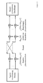
- this description is limited to the problem of oscillator phase noise, as exemplified in the FIG. 1 is shown.
- phase noise at the transmitter with exp ( j ⁇ Tx ( t )) as well as at the receiver with exp ( j ⁇ R x ( t )) influences the mixing process.
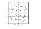
- the resulting multiplicative disturbance leads to a distortion of the constellation diagram, as is the case for a 16-QAM and an IEEE 802.11a-type related system in the FIG. 2 becomes visible.
- phase noise there are various approaches in the literature for modeling phase noise in baseband.
- a Model which does not directly indicate the phase fluctuation ⁇ ( t ), but considers a stochastic time shift ⁇ ( t ) over a temporally fluctuating instantaneous frequency.
- the output signal of an ideal oscillator is an exactly periodic signal x 0 ( t ).
- Disturbances, such as thermal noise, 1 / f noise and shot noise in the oscillator lead to a deviation from this ideal signal form.
- variable ⁇ ( t ) describes a realization of the already mentioned time-varying, random time shift ⁇ ( t ), whose modeling and statistical properties are considered in more detail in the course of this description.
- the second term ⁇ ( t ) describes an additive amplitude shift and is called orbital deviation. In a stable system, which is assumed here, the orbital deviation assumes negligible values and will therefore not be considered further in the following analyzes.
- a simple and widespread modeling of the phase noise is based on the operation of a free-running oscillator, whose block diagram in FIG. 3 is shown.
- a free-running oscillator basically consists of a voltage controlled oscillator (engl. VCO (voltage controlled oscillator) in which an input voltage u (t) to a frequency f (t) is mapped.
- VCO voltage controlled oscillator
- the input voltage at the oscillator then results as a linear combination of a constant voltage u 0 and a time-dependent, stochastic voltage fluctuation ⁇ u (t).
- ⁇ u (t) a constant voltage
- ⁇ f (t) a time-dependent, stochastic voltage fluctuation
- variable ⁇ ( t ) represents the stochastic phase noise of an oscillator whose realization corresponds to a random, instantaneous phase position of the periodic output signal.
- the linear mapping of the Gaussian disturbance variables at the input of the oscillator leads to a standard Gaussian process ⁇ ( t ), weighted with the oscillator- specific constant c vco , whose mean value is zero and whose variance is one.
- the stochastic integral over a standard Gaussian process is called the Wiener process W (t), whose variance increases linearly with time and continues to be averaged.
- Equation 6 implies that the phase noise of an oscillator can be characterized by a constant c vco .
- An analytical expression for the constant c vco is defined via the output power density spectrum (LDS) of the disturbed oscillator output signal and will be given here by way of example for a purely sinusoidal oscillator signal.
- LDS output power density spectrum
- phase noise in the digital baseband leads to a multiplicative disturbance at the transmitter as well as at the receiver.
- phase noise is present on all antennas with the same implementation. This assumption is justified, since several oscillators operating in parallel would increase the hardware expenditure significantly.
- the mobile terminal should be as cheap as possible in its production, which is why in many wireless networks, the analog front end of the terminal is equipped worse than the access point.
- the phase noise at the receiver side is significantly more dominant.
- transmitter-side phase noise can be considered as equivalent receiver phase noise.
- the result is a block diagonal matrix H with the elements of the transfer function of the channel.
- the diagonal matrix ⁇ diag ( e ) ⁇ I N Rx represents the receiver-side phase noise with Ng + N of non-zero elements. Adding and removing the guard interval does not change the basic structure of ⁇ , but only reduces the dimension of the matrix.
- the transmission system according to equation 9 can be represented in a known compact form as The right-hand representation corresponds to a circular convolution ( ⁇ ) of the transmitted signal with the frequency domain representation of the phase noise.
- ⁇ a circular convolution
- phase noise harmonic a synonym for the frequency domain representation of the phase noise and the term phase noise harmonic is used.
- the author has developed a method which determines the phase noise in the time domain using a Kalman approach.
- the developed algorithm is completely transparent to the underlying transmission method and can be used for single or multi-carrier concepts.
- the focus of this description, however, is in OFDM as a multicarrier method, which is why the Kalman filter is also presented for this application.
- Kalman filtering to estimate the phase noise was already considered in [18], but the algorithm presented there refers to a pure estimate of the CPE from OFDM symbol to OFDM symbol. Approaches to Scan-level phase-noise averaging has been demonstrated by the author [19], which also forms the basis of this section. In addition, the work presented methods for reducing complexity.
- FIG. 4 In the sense of a closed treatise is in the FIG. 4 once again presented a single-antenna transmission system with phase noise.
- FIG. 5 At the receiver side, an iterative equalization and detection of the received data, as shown in FIG. 5 is shown.
- Phase Noise Estimation and Compensation module The main focus of the following description is on the Phase Noise Estimation and Compensation module.
- the compensation can be explained quickly because it consists in multiplying the receive sequence by the conjugate complex of the estimated phase noise trajectory.
- FIG. 6 shows a schematic representation of a generalized system model with Kalman tracking, that is, estimation of the system size v [ n ].
- phase noise estimation algorithm using unscented Kalman filtering
- the necessary inputs namely the Observation size r and the observation noise ⁇ r , are given as follows.
- y n a ⁇ n ⁇ e j ⁇ n + ⁇ ⁇ a n ⁇ e j ⁇ n + ⁇ n .
- Var [ ⁇ S ] as the vector of the variances of the soft symbols and of the estimation error whose calculation is given by the L values, see also [23].
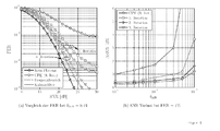
- FIG. 8a Figure 4 shows a comparison of the performance of an antenna system between the estimation of multiple phase noise harmonics in the frequency domain and Kalman filtering. It can be seen a significant increase in performance, for example, results after the first iteration, a gain of about 2.5 dB at a target error rate of 1%.
- Kalman approach is limited by the error propagation during the iterations, because for the computation of the time domain sequence a all estimated transmit symbol vectors are needed, whereas in the frequency domain estimation only a relatively small set of reliable subcarriers are used.
- This error propagation also explains the visible error carpet because performance is determined by the error rate in the 0th iteration. If this is low, then there is also a low residual error rate.
- This fact also underlines the advantage of Kalman filtering, namely that no basic assumptions are made of the process to be estimated. A concentrated high squared error between the true and the estimated phase fluctuation at the edges of an OFDM symbol, as occurs in a frequency domain estimate, due to the inherent assumption of a periodic signal, does not occur in Kalman filtering.
- Kalman filtering is that this method can be used for both single and multi-carrier systems.
- the algorithm makes no basic assumptions about the course of the Phasenrauschtrajektorie.
- This section includes a modification of unscented Kalman filtering to estimate multiplicative phase disturbances.
Landscapes
- Engineering & Computer Science (AREA)
- Computer Networks & Wireless Communication (AREA)
- Signal Processing (AREA)
- Noise Elimination (AREA)
- Feedback Control In General (AREA)
Abstract
Description
- Die Erfindung betrifft ein Verfahren zur Schätzung und Kompensation von nichtlinearem, multiplikativen Phasenrauschen, bei welchem ein Phasenrauschtrajektor φ̂, welcher eine Schätzung einer Realisierung φ eines Phasenrauschprozesses abbildet, geschätzt wird, mittels dessen eine Kompensation des Phasenrauschens erfolgt.
- Unter Phasenrauschen ist eine zufällige Veränderung der Phasenlage eines Empfangssignals zu verstehen, wobei diese Störung zum Beispiel durch nicht perfekte Oszillatoren, Schwankungen des Abtastzeitpunktes während der Analog-Digital-Wandlung oder aber auch durch Vibrationen eines Empfängers oder einer Empfängerschaltung verursacht werden kann.
- Das Phasenrauschen hat einen Einfluss auf die Lage eines Empfangssymbols, welches beispielsweise in einem Konstellationsdiagramm dargestellt werden kann.
- Besonders in Systemen mit mächtigen Modulationsalphabeten und damit einhergehend engen Entscheidungsregionen zeichnet sich das Phasenrauschen besonders stark ab, denn gerade solche Systeme sind sehr sensibel gegenüber Phasenstörungen.
- Somit ergibt sich die Notwendigkeit einer Kompensation des Phasenrauschens.
- Die durch Phasenrauschen verursachte stochastische Phasenfluktuation führt zu zwei wesentlichen Effekten, dem Gleichphasenfehler (engl. "common phase error" bzw. CPE) und der Unterträgerinterferenz (ICI...intercarrier interference). Speziell für einen gegebenen Fall von Phasenrauschen am Empfänger lässt sich der Empfangsvektor Y im Frequenzbereich schreiben als

- Während die ICI aufgrund der Struktur von Υ für jeden Unterträger unterschiedlich ist, entspricht der CPE einer konstanten Rotation aller Unterträger, unabhängig von deren Lage im Spektrum. Diese Rotation ist jedoch unterschiedlich von OFDM-Symbol zu OFDM-Symbol und unterstreicht somit die Notwendigkeit einer Kompensation.
- Erfolgt keine Kompensation, so ist das Phasenrauchen, welches auch als Phasenfluktuation bezeichnet wird, über die OFDM Symbole so groß, dass selbst bei geringem Phasenrauschen eine Leistungsdegradation des Systems eintritt, welche keine zuverlässige Übertragung der Nutzinformation mehr erlaubt.
- Der Gleichphasenfehler eines OFDM-Symbols entspricht dem Gleichanteil der Fouriertransformation einer Phasenrauschrealisierung und approximiert auch den mittleren Phasenversatz φ̅, wie die folgende Gleichung zeigt

- In diesem Zusammenhang repräsentiert Δφ[n] die instantane Phasenabweichung vom mittleren Phasenversatz φ̅. Ist diese Phasenabweichung verschwindend gering, so entspricht der CPE exakt der Fouriertransformation des mittleren Phasenversatzes.
- Die Struktur des CPE erlaubt eine einfache Schätzung und Kompensation des Gleichphasenfehlers, wobei besonders die Schätzung mittels bekannter linearer Schätzverfahren realisiert werden kann. Für einen linearen Schätzer berechnet sich der CPE durch

und entspricht einer linksseitigen Multiplikation des Empfangsvektors Y mit einer Filtermatrix g. Die einfachste Filtermatrix resultiert aus dem ZF-Ansatz, welcher auch vorzugsweise in der Literatur, beispielsweise in [24] diskutiert wird. - Ausgangspunkt sind Pilotsymbole, welche am Empfänger bekannt sind, sowie der Kanal an diesen Pilotpositionen. Definiert P = {p 1,p 2,··· ,p P} die
- Menge der Pilotpositionen, so entspricht

gleich dem Empfangssignal einer störungsfreien Übertragung der Pilotsymbole, so dass die Filtermatrix für die Schätzung des CPEs angegeben werden kann als
- Der Vorteil der ZF-Schätzung ist die geringe Komplexität, denn neben einfacher Vektormultiplikation erfolgt nur die Invertierung eines skalaren Wertes. Demgegenüber steht der Nachteil einer eventuellen Rauschverstärkung, da das Rauschen im Filteransatz nicht mit berücksichtigt wird.
- Die Rauschvarianz wird beim MMSE (MMSE ... Minimum mean squared error)-Filteransatz mit einbezogen, jedoch auf Kosten einer nicht perfekten Interferenzunterdrückung. Eine signifikante Verbesserung der Leistungsfähigkeit konnte jedoch nicht festgestellt werden.
- Die Phasenrauschschätzung kann beispielsweise im Frequenzbereich durchgeführt werden, wie nachfolgend ausgeführt.
- Der Einfluss von Phasenrauschen auf die Leistungsfähigkeit von OFDM-Systemen wurde schon eingehend in der Literatur [25] diskutiert. Dabei zeigt sich die kontinuierliche Präzisierung der Effekte von Phasenrauschen, angefangen von der reinen Betrachtung des CPEs bis hin zur Modellierung der ICI.
- Erste Ansätze zur Kompensation der ICI in einer reinen AWGN-Umgebung (AWGN ... Additive white Gaussian noise) sind in [7] gegeben. Aufbauend auf einer Taylorreihenapproximation der Phasenrauschtrajektorie erfolgt eine MMSE basierte Schätzung dieser. Die mathematische Beschreibung, die ICI im Frequenzbereich als gewichtete Summe von Sendesymbol, Kanal und Harmonische des Phasenrauschens darzustellen, wurde erstmalig und unabhängig voneinander in den Arbeiten [26] und [27] vorgestellt. Beide Autoren entwickelten in ihren Folgearbeiten verbesserte Algorithmen zur Kompensation der ICI. So sind in [8] Verfahren vorgestellt, welche die Phasenrauschharmonischen mit Hilfe eines MMSE-Ansatzes schätzen. Es wird aber in der Arbeit immer davon ausgegangen, dass der Kanal vollkommen bekannt ist und die gesendeten Symbole zum Teil a-priori bekannt sind, zum Beispiel durch eine vorangegangene CPE-Korrektur und - Entzerrung. Die eingeschränkte Kenntnis der gesendeten Symbole wird in [9] durch iterative Verfahren zum Teil aufgehoben. Durch Einbeziehen des Decoders ist eine zuverlässigere Bestimmung der gesendeten Symbole möglich, was den Schätzprozess verbessert. Jedoch wird in der Arbeit der Kanal als bekannt vorausgesetzt. Außerdem ist die Auswahl der zur Schätzung des Phasenrauschens benötigten Unterträger nicht optimal im Sinne der vom Decoder gegebenen a-priori-Information. Ein weiterer Verbesserungspunkt ist die Berechnung der Restinterferenz.
- Die Phasenrauschschätzung kann beispielsweise im Zeitbereich durchgeführt werden, wie nachfolgend ausgeführt.
- In der Literatur existieren vereinzelt Ansätze das Phasenrauschen im Zeitbereich zu schätzen. Eine Auswahl vielversprechender Verfahren ist im ersten kurzen Teil dieses Abschnittes gelistet. Der Nachteil der dort beschriebenen Algorithmen ist jedoch, dass sie entweder für Ein- oder für Mehrträgerverfahren konzipiert sind und somit nicht universell einsetzbar sind.
- In [10] und [11] sind erste Vorschläge für Mehrträgerverfahren dargestellt. Die grundlegende Idee ist, die Phasenrauschtrajektorie mit Hilfe von Trainingssymbolen und einem LS-Ansatzes zu bestimmen. Dabei wird das Phasenrauschen durch ein linearisiertes Modell approximiert, welches aber nur bedingt das wahre Verhalten des Phasenrauschens widerspiegelt.
- In [12] wurde als erstes die Idee einer gemeinsamen Phasenrauschschätzung und Decodierung vorgestellt. Der Ansatz beruht auf dem Prinzip des Austausches von Informationen (Nachrichten) (engl. MP ... massage passing) zwischen Knotenpunkten in einem Faktorgraphen (engl. FG ... factor graph), siehe [13], wie es zum Beispiel bei der Decodierung von LDPC Codes schon bekannt ist. Um dieses Verfahren durchzuführen, muss eine Faktorisierung der Verbundwahrscheinlichkeitsdichte aller Variablen erfolgen.
- Diese Dichte zu bestimmen, ist besonders in Systemen mit mehreren Störgrößen sehr umständlich, weshalb bis jetzt nur AWGN-Kanäle untersucht wurden. Eine Erweiterung dieses Ansatzes erfolgte in den Arbeiten von [14] und [15] durch einen Vergleich verschiedener Faktorisierungsarten bezüglich ihrer Leistungsfähigkeit und Komplexität. Die erzielten Ergebnisse dieses Ansatzes sind durchaus beeindruckend, jedoch sind neben der Beschränkung auf AWGN-Kanäle nur Einträgerverfahren untersucht worden.
- Für Mehrträgerverfahren und frequenzselektive Kanäle gibt es erste Beiträge in der Arbeit [16], wo der Ansatz der Faktorgraphbeschreibung und der damit verbundene sum-product (engl.) Algorithmus zur gemeinsamen Schätzung von Phasenrauschen und Frequenzversatz genutzt wird. Jedoch ist in dieser Arbeit nicht mehr die Rede von einer gemeinsamen Decodierung der Symbole und Schätzung der Störgrößen, stattdessen werden der Kanal als auch die Sendesymbole als bekannt vorausgesetzt. Die Kenntnis der Sendesymbole stützt sich dabei auf einen iterativen Detektor-Decoder-Ansatz.
- Ein weiteres Verfahren, welches auch einen iterativen Ansatz zur Schätzung des Phasenrauschens im Zeitbereich hat, ist in der Veröffentlichung von [17] behandelt. Auch dort ist die Beschränkung auf AWGN-Kanäle fallen gelassen worden. Mit den L-Werten des Dekoders und unter der Annahme, dass das Phasenrauschen einer Gaußverteilung genügt, wird eine Kostenfunktion definiert, deren Lösung auf ein Regelkreisprinzip hinausläuft. Das in der Arbeit vorgestellte Optimierungsverfahren setzt jedoch als Nebenbedingung, dass jedes Konstellationssymbol die gleiche Leistung hat, das heißt, der Abstand vom Koordinatenursprung für jedes Sendesymbol identisch ist. Somit werden höher valente QAM-Übertragungsverfahren ausgeschlossen.
- Der Erfindung liegt somit die Aufgabe zugrunde, ein Verfahren zur Schätzung und Kompensation von nichtlinearem, multiplikativen Phasenrauschen zu schaffen, mit welchem eine Reduzierung des Aufwands erreicht und die Flexibilität des Verfahrens verbessert wird.
- Gemäß der Erfindung wird die Aufgabe bei einem Verfahren zur Schätzung und Kompensation von nichtlinearem, multiplikativen Phasenrauschen der eingangs genannten Art dadurch gelöst, dass der Phasenrauschtrajektor φ̂ mittels einer unscented-Kalman-Filterung ermittelt wird, wobei die Eingangsgrößen für die unscented-Kalman-Filterung r[n] und ξ r [n] ermittelt werden
gemäß
und sich die Ausgangsgröße φ̂ der unscented-Kalman-Filterung
gemäß
ergibt, wobei K eine Kalman-Verstärkung nach
r ein Empfangssignal und r̂ eine Wichtung der transformierten Sigmapunkte ist. - Die erfindungsgemäß ermittelten Phasenrauschtrajektoren φ̂ werden zur Kompensation des Phasenrauschens genutzt. Diese kann zum einen durch eine Multiplikation der Empfangsfolge mit dem konjugiert komplexen der geschätzten Phasenrauschtrajektoren φ̂ im Zeitbereich oder mittels einer Entfaltung im Frequenzbereich erfolgen.
- Die Erfindung soll nachfolgend anhand eines Ausführungsbeispiels näher erläutert werden. In den zugehörigen Zeichnungen zeigt
- Fig. 1
- eine Darstellung des Phasenrauschens an einem Sender und einem Empfänger,
- Fig. 2
- eine Darstellung eines 16-QAM-Konstellations- diagrams unter Phasenrauschen mit einem freilaufenden Oszillator mit einer Oszillatorkonstante: cvco = 3 * 10-17s,
- Fig. 3
- ein Blockschaltbild eines spannungsgesteuerten Oszillators (VCO),
- Fig. 4
- eine Darstellung eines OFDM-Übertragungssystems,
- Fig. 5
- eine Abbildung der OFDM-Empfängerseite,
- Fig. 6
- ein generalisiertes Systemmodell mit Kalman- Filterung,
- Fig. 7
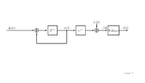
- ein phasenrauschbasiertes Systemmodell mit Kalman- Filterung,
- Fig. 8a
- eine Darstellung des FER Verlust nach ICI- Korrektur, HiperLanA Kanal, 64-QAM,
- Fig. 8b
- eine Darstellung des SNR Verlust nach ICI-
- Fig. 9
- Korrektur, HiperLanA Kanal, 64-QAM, ein weiteres Phasenrauschbasiertes Systemmodell mit Kalman-Filterung und
- Fig. 10
- eine Algorithmus zur Durchführung des erfindungsgemäßen Verfahrens.
- Unter Phasenrauschen ist eine zufällige Veränderung der Phasenlage des Empfangssignals zu verstehen, wobei diese Störung zum Beispiel durch nicht perfekte Oszillatoren, wie in [1] beschrieben, Schwankungen des Abtastzeitpunktes während der Analog-Digital-Wandlung, wie in [2] dargestellt, aber auch durch Vibrationen, wie in [3] ausgeführt, verursacht werden kann.
- Anhand dieser Beispiele zeigt sich, dass die Quellen von Phasenrauschen vielfältig sind und das Phasenrauschen in den verschiedensten Anwendungsgebieten auftritt. Als Anwendungsgebiet beschränkt sich diese Beschreibung auf die Problematik des Oszillatorphasenrauschens, wie es beispielhaft in der
Figur 1 dargestellt ist. Anhand der Abbildung ist ersichtlich, dass Phasenrauschen am Sender mit exp(jφ Tx (t)) als auch am Empfänger mit exp(jφ Rx (t)) den Mischprozess beeinflusst. Die dabei entstehende multiplikative Störgröße führt zu einer Verzerrung des Konstellationsdiagrams, wie es für eine 16-QAM und einem IEEE 802.11a artverwandten System in derFigur 2 sichtbar wird. Für eine mögliche Kompensation gilt es, diese Fluktuationen möglichst gut zu modulieren und deren Einfluss auf die Signalübertragung zu charakterisieren. - In der Literatur existieren verschiedene Ansätze zur Modellierung von Phasenrauschen im Basisband. Um das Phasenrauschen möglichst akkurat zu beschreiben, wird ein Modell verwendet, das die Phasenfluktuation φ(t) nicht direkt angibt, sondern über eine zeitlich schwankende Momentanfrequenz eine stochastische Zeitverschiebung α(t) betrachtet. Das Ausgangssignal eines idealen Oszillators ist ein exakt periodisches Signal x 0(t). Störungen, wie thermisches Rauschen, 1/f-Rauschen und Schrotrauschen im Oszillator führen zu einer Abweichung von dieser idealen Signalform. In Anlehnung an die in [1] und [4] dargestellten Ausführungen werden alle Rauschquellen zu einer weißen, gaußschen Störgröße zusammengenommen und ein Modell eingeführt, dass eine Realisierung des Ausgangssignals xs (t) eines realen Oszillators wie folgt angeben lässt

- Die Variable α(t) beschreibt eine Realisierung der schon erwähnten zeitveränderlichen, zufälligen Zeitverschiebung α(t), deren Modellierung und statistischen Eigenschaften im Laufe dieser Beschreibung näher betrachtet werden. Der zweite Term η(t) beschreibt eine additive Amplitudenverschiebung und wird als Orbitalabweichung bezeichnet. In einem stabilen System, von dem hier ausgegangen wird, nimmt die Orbitalabweichung vernachlässigbar kleine Werte an und wird deshalb in den folgenden Analysen nicht weiter betrachtet.
- Zusätzlich wird angenommen, dass das Oszillatorausgangssignal x 0(t) nur aus einer Grundwelle besteht. Eine Erweiterung der nichtlinearen Analyse auf zusätzliche Oberwellen sowie gefärbtes Rauschen wurde in [5] vorgestellt. Weitere tiefgründige Analysen von Phasenrauschen und dessen Einfluss auf Abtast-Jitter in Analog-Digital-Wandlern sind in der Dissertation [2] diskutiert.
- Eine einfache und weit verbreitet Modellierung des Phasenrauschens beruht auf der Wirkungsweise eines freilaufenden Oszillators, dessen Blockschaltbild in
Figur 3 dargestellt ist. Ein freilaufender Oszillator besteht prinzipiell aus einem spannungsgesteuerten Oszillator (engl. VCO (voltage controlled oscillator), bei dem eine Eingangsspannung u(t) auf eine Frequenz f(t) abgebildet wird. Analog zu [1] wird angenommen, dass alle Rauschquellen zu einer weißen, gaußschen Rauschquelle am Eingang des Oszillators zusammengefasst werden können. - Die Eingangsspannung am Oszillator ergibt sich dann als Linearkombination einer konstanten Spannung u 0 und einer zeitabhängigen, stochastischen Spannungsschwankung Δ u (t). Zusätzlich wird angenommen, dass die durch die Rauschquelle hervorgerufenen kleinen Spannungsänderungen Δ u (t) zu einer linearen Änderung der Frequenz Δ f (t) am Ausgang des Oszillators führen. Die Frequenz am Ausgang des spannungsgesteuerten Oszillators lässt somit schreiben als

- Die zufälligen Schwankungen der Momentanfrequenz führen zu einer zufälligen Änderung des Oszillatorausgangsignals, gegeben als

- Die Variable φ(t) stellt das stochastische Phasenrauschen eines Oszillators dar, deren Realisierung einer zufälligen, instantanen Phasenlage des periodischen Ausgangssignals entspricht.
- Mit Hilfe von Gleichung 1 lässt sich folgender formale Zusammenhang zwischen der stochastischen Zeitverschiebung α(t), dem Phasenrauschen und der normierten Momentanfrequenz herstellen

- Die lineare Abbildung der gaußschen Störgrößen am Eingang des Oszillators führt zu einem mit der oszillatorspezifschen Konstante cvco gewichteten Standard-Gaußprozess ζ(t), dessen Mittelwert null und dessen Varianz eins sind. Das stochastische Integral über einen Standard-Gaußprozess wird als Wienerprozess W (t) bezeichnet, dessen Varianz linear mit der Zeit steigt und weiterhin mittelwertfrei ist. Der Wienerprozess ist zeitlich nicht differenzierbar, jedoch lässt sich ein Zusammenhang zu einem Standard-Gaußprozess über einem differentiellen Wienerprozess definieren als

- Wird ein Abtastintervall Δ(t) eingeführt, kann die Definition des differentiellen Wienerprozesses dahingehend ausgenutzt werden, um diskrete Zeitfluktuationen α[n] an gegebenen Abtastpunkten n · Δt zu generieren. Die Lösung besteht darin, das Integral in Gleichung 4 durch eine Summe von Bereichsintegralen auszudrücken

- Für den Zeitpunkt n · Δt = 0 existiert eine Realisierung des Gaußprozesses ζ(0). Jedes Bereichsintegral resultiert für sich in einen unabhängigen Wienerprozess W i (Δt), der einer mittelwertfreien Gaußverteilung mit Varianz Δt genügt und mitgewichtet ist. Die Varianz der diskreten Zeitverschiebung zum Zeitpunkt n · Δt ergibt sich als Summe der Einzelvarianzen und steigt linear mit der Zeit


- Gleichung 6 impliziert, dass das Phasenrauschen eines Oszillators durch eine Konstante cvco charakterisiert werden kann. Ein analytischer Ausdruck für die Konstante cvco ist über das Ausgangs-Leistungsdichtespektrum (LDS) des gestörten Oszillatorausgangssignals definiert und soll hier exemplarisch für ein rein sinusförmiges Oszillatorsignal angegeben werden.
- In der Veröffentlichung [1] ist eine Verallgemeinerung für Oszillatorsignale mit Oberwellen dargestellt.
- Nachfolgend wird das der Erfindung zugrundeliegende Systemmodell erläutert. Phasenrauschen führt im digitalen Basisband zu einer multiplikativen Störung am Sender sowie am Empfänger. Im Bezug auf Mehrantennensysteme wird angenommen, dass ein Oszillator alle Antennen speist, das heißt, das Phasenrauschen ist an allen Antennen mit der gleichen Realisierung vorhanden. Diese Annahme ist gerechtfertigt, da mehrere parallel arbeitende Oszillatoren den Hardwareaufwand bedeutend erhöhen würden.
- Eine Systembeschreibung mit mehreren Oszillatoren ist möglich und prinzipiell sind in die diesem Kapitel betrachteten Verfahren zur Phasenrauschkompensation in der Lage, ein solches System zu entzerren, jedoch wäre in einem solchen Fall eine individuelle Abarbeitung jedes einzelnen Antennenstroms nötig, was die Komplexität linear mit der Anzahl der Antennen anwachsen lässt.
- Aus ökonomischer Sicht sollte das mobile Endgerät in seiner Produktion so günstig wie möglich sein, weshalb in vielen drahtlosen Netzwerken das analoge Frontend des Endgerätes schlechter ausgestattet ist als der Accesspoint. Im Fall eines Datenverkehrs vom Accesspoint zum Endgerät kann dann mit guter Näherung davon ausgegangen werden, dass das Phasenrauschen an der Empfängerseite wesentlich dominanter ist. Zusätzlich wurde in der Arbeit [6] gezeigt, dass senderseitiges Phasenrauschen als äquivalentes Empfängerphasenrauschen betrachtet werden kann. Das Zeitsignal an der Empfangsantenne d unter Phasenrauschen ergibt sich somit zu

wobei * für die bekannte Faltung zwischen Sendesignal und Kanal steht. Die statistischen Eigenschaften des AWGNs bleiben durch die Multiplikation mit dem Phasenrauschen unberührt, da nur eine zusätzliche Phasendrehung eintritt. In dieser Beschreibung wird eine blockweise Übertragung nach dem Prinzip des MIMO-OFDM-Konzept betrachtet. Für eine kompakte Notation erfolgt dafür die Beschreibung in Vektor-Matrix-Form über alle Antennen. Der Empfangsvektor im Frequenzbereich lässt sich darstellen als
mit ⊗ als Kroneckerprodukt. Mit Hilfe von geeigneten
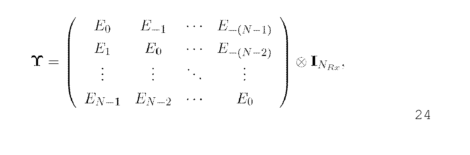
Matrizenmanipulationen kann die zirkulare Blockmatrix (ζ⊗I NRx )h(ε⊗I NTx ) durch DFT Operationen diagonalisiert werden. - Das Ergebnis ist eine Blockdiagonalmatrix H mit den Elementen der Übertragungsfunktion des Kanals. Die Diagonalmatrix υ = diag(e)⊗I N Rx repräsentiert das empfängerseitige Phasenrauschen mit Ng + N von null verschiedenen Elementen. Das Hinzufügen und Entfernen des Schutzintervalls ändert nichts an der grundsätzlichen Struktur von ν, sondern reduziert nur die Dimension der Matrix. Die sich anschließende rechtsseitige und linksseitige Multiplikation mit den DFT-Matrizen führt zu einer zirkulanten Matrix der Form

- Die Elemente dieser Matrix entsprechen der zeitdiskreten Fouriertransformation des Phasenrauschvektors e
mit
als Frequenzbereichsrepräsentation einer
Phasenrauschtrajektorie. Das Übertragungssystem nach Gleichung 9 lässt sich in bekannter kompakter Form darstellen als
- Um die Einschränkungen der existierenden Verfahren zu umgehen, wurde vom Autor ein Verfahren entwickelt, welches das Phasenrauschen im Zeitbereich mit Hilfe eines Kalman-Ansatzes bestimmt. Der entwickelte Algorithmus ist dabei völlig transparent gegenüber dem zugrundeliegenden Übertragungsverfahren und kann für Ein- oder Mehrträgerkonzepte verwendet werden. Der Fokus dieser Beschreibung liegt jedoch bei OFDM als Mehrträgerverfahren, weshalb der Kalman-Filter auch für diese Anwendung vorgestellt wird.
- Kalman-Filterung zur Schätzung des Phasenrauschens wurde schon in [18] betrachtet, jedoch bezieht sich der dort präsentierte Algorithmus auf eine reine Schätzung des CPEs von OFDM-Symbol zu OFDM-Symbol. Ansätze zur Phasenrauschermittelung auf Abtastebene wurden vom Autor in der Arbeit [19] gezeigt, welche auch die Grundlage dieses Abschnittes bildet. Zusätzlich wurden in der Arbeit Verfahren zur Reduktion der Komplexität vorgestellt.
- Im Sinne einer geschlossenen Abhandlung ist in der
Figur 4 noch einmal ein Einantennenübertragungssystem mit Phasenrauschen dargestellt. An der Empfängerseite erfolgt eine iterative Entzerrung und Detektion der Empfangsdaten, wie es inFigur 5 gezeigt ist. - Das Hauptaugenmerk der folgenden Beschreibung richtet sich auf das Modul Phasenrausch-Schätzung und -Kompensation. Die Kompensation lässt sich schnell erklären, denn sie besteht darin, die Empfangsfolge mit dem Konjugiert komplexen der geschätzten Phasenrauschtrajektorie zu multiplizieren.
- Die ingenieurstechnische Leistung besteht vielmehr darin, die für die Kompensation benötigte Phasenrauschtrajektorie zu schätzen, wofür an dieser Stelle eine modifizierte Kalman-Filterung verwendet wird.
-
Figur 6 zeigt eine schematische Darstellung eines generalisierten Systemmodells mit Kalman-Tracking, das heißt Schätzung der Systemgröße v̂[n]. - Anstatt das Phasenrauschen mit Hilfe eines zufälligen Vektors zu modellieren, wird die Phasenrauschfluktuationen φ[n] selber betrachtet

- Mit dem entscheidenden Vorteil, dass Δφ[n] für einen freilaufenden Oszillator direkt proportional zur stochastischen Zeitverschiebung α[n] aus Gleichung 6 ist und somit keine Einschränkungen für den Wertebereich existieren. Das für eine solche Modellierung angepasste Blockdiagramm ist in
Figur 7 dargestellt. Es zeigt sich jedoch, dass mit e (·) eine nichtlineare Beobachtungsmatrix gegeben ist, was zur Folge hat, dass ein linearer Kalman-Ansatz nicht mehr anwendbar ist. Dieses Problem kann zum Beispiel durch die Strategie des erweiterten Kalman-Filters (engl. EKF ... extended kalman filter) gelöst werden, beidem die nichtlineare Funktion durch eine Taylorreihenapproximation wieder auf eine lineare Funktion abgebildet wird, wie in [20] beschrieben. Eine solche Approximation kann aber zu großen Abweichungen zwischen der wahren Korrelationsmatrix der Beobachtungsgröße und der durch die Linearisierung modifizierten Korrelationsmatrix führen. Außerdem beinhaltet die Linearisierung die Berechnung einer Jacobimatrix, welche rechentechnisch aufwändig ist. Aufgrund der genannten Nachteile wird an dieser Stelle eine Form des Kalman-Filters verwendet, welche auf der so genannten unscented-Transformation basiert, wie in [21] und [22]dargestellt. Die Grundidee dieser Transformation ist die Tatsache, dass es einfacher ist, eine Verteilung genauer zu approximieren, als eine beliebige nichtlineare Abbildung. Für die Approximation wird ein Satz von Punkten (SP ... sigma points) der nichtlinearen Transformation unterzogen und anhand deren Lage im Bildbereich wird die gesuchte Kovarianzmatrix bestimmt. In [21] ist gezeigt, dass schon wenige SP für eine akkurate Approximation ausreichen. Die Wahl der SP geschieht dabei nicht zufällig, sondern erfolgt anhand einer vorgegeben Berechnungsvorschrift basierend auf Mittelwert und Varianz der Systemgröße vor der Transformation. - Eine detaillierte Darstellung des Algorithmus zur Schätzung des Phasenrauschens mit Hilfe der unscented Kalman-Filterung ist in dieser Beschreibung weiter hinten zu finden. Die dafür nötigen Eingangsgrößen, namentlich die Beobachtungsgröße r und das Beobachtungsrauschen ξ r , sind wie folgt gegeben. Das Empfangssignal unter Phasenrauschen lässt sich für ein Einantennensysteme schreiben als

- Nach erfolgreicher CPE-Korrektur und -Decodierung ist eine erste Schätzung Ŝ der Sendesymbole S vorhanden, was im Zeitbereich einer Folge ŝ entspricht und zum nachfolgenden Ausdruck führt

- Mit Hilfe dieses Terms lässt sich das Empfangssignal auch darstellen als

wodurch sich nach Division mit â die gewünschte Beobachtungsgröße r ergibt
- Der Parameter ξ r [n] entspricht dem der transformierten Störgröße additiv überlagertem Beobachtungsrauschen, wie in der
Figur 7 gezeigt, dessen Varianz für die Kalman-Filterung eine entscheidende Rolle spielt, und sich angeben lässt als
- Zu beachten ist, dass â[n] nicht stochastisch ist, sondern durch die Decodierung einen deterministischen Charakter besitzt. Somit ergibt sich folgende Kette

- Die Varianz von Δa[n] lässt sich als Vektor über ein OFDM-Symbol, aufgrund der Unabhängigkeit der Sendesymbole im Frequenzbereich, darstellen als

mit Var[Δ S ] als Vektor der Varianzen der weichen Symbole bzw. des Schätzfehlers, deren Berechnung über die L-Werte gegeben ist, siehe auch [23]. Am Ausgang des Kalman-Filters ergibt sich letztendlich eine geschätzte Trajektorie, mit der das Phasenrauschen im Zeitbereich kompensiert wird. - Nachfolgend werden die Ergebnisse der erfindungsgemäßen Lösung dargestellt.
Figur 8a zeigt einen Vergleich der Leistungsfähigkeit eines Einantennensystems zwischen der Schätzung mehrere Phasenrauschharmonischer im Frequenzbereich und Kalman-Filterung. Es ist eine deutliche Leistungssteigerung zu erkennen, so ergibt sich zum Beispiel schon nach der ersten Iteration ein Gewinn von circa 2,5 dB bei einer Zielfehlerrate von 1%. - Jedoch ist der Kalman-Ansatz durch die Fehlerfortpflanzung während den Iterationen limitiert, denn für die Berechnung der Zeitbereichsfolge a werden alle geschätzten Sendesymbolvektoren benötigt, währenddessen bei der Frequenzbereichsschätzung nur ein relativ kleiner Satz von zuverlässigen Unterträgern verwendet wird. Diese Fehlerfortpflanzung erklärt auch den sichtbaren Fehlerteppich, denn die Leistungsfähigkeit wird durch die Fehlerrate in der nullten Iteration bestimmt. Ist diese gering, so ergibt sich auch einen niedrige Restfehlerrate. Diese Tatsache unterstreicht aber auch den Vorteil der Kalman-Filterung, nämlich dass keine Grundannahmen an den zu schätzenden Prozess gestellt werden. Ein konzentrierter hoher quadratischer Fehler zwischen der wahren und der geschätzten Phasenfluktuation an den Rändern eines OFDM-Symbols, wie es bei einer Frequenzbereichsschätzung vorkommt, aufgrund der inhärenten Annahme eines periodischen Signals, tritt bei der Kalman-Filterung nicht ein.
- Um die Leistungsfähigkeit der Kalman-Filterung weiter zu beurteilen, ist in der
Figur 8b der SNR-Verlust über der relativen Oszillatorgüte bei einer Zielfehlerrate von 1% abgetragen. Ein Vergleich mit der Literatur verdeutlicht, dass der Kalman-Filteransatz über den Iterationen prinzipiell immer bessere Ergebnisse erzielt als die Frequenzbereichsschätzung. - Dabei werden im mittleren Phasenrauschbereich Gewinne um die 0,5 dB erreicht, während bei starken Phasenrauschen bis zu 2,5 dB weniger SNR benötigt wird.
- Ein bedeutender Vorteil der Kalman-Filterung ist, dass dieses Verfahren sowohl für Ein- als auch für Mehrträgersysteme einsetzbar ist. Außerdem stellt der Algorithmus keine Grundannahmen gegenüber dem Verlauf der Phasenrauschtrajektorie.
- Dieser Abschnitt beinhaltet eine Modifikation der unscented Kalman-Filterung zu Schätzung von multiplikativen Phasenstörungen.
- Ausgangspunkt des gegebenen Algorithmus, welcher in der
Figur 10 als Ablaufplan dargestellt ist, ist eine Modellbildung nachFigur 9 , wo das Phaseninkrement als Prozessrauschen interpretiert wird. Aufbauend auf diesem Gedanken ist in vorigem Abschnitt eine systemtheoretische Beschreibung eingeführt, die erlaubt Phasenfluktuationen mit Hilfe einer unscented Kalman-Filterung zu schätzen. Die dazu nötigen Größen sind der Eingabevektor r[n] gemäß der Gleichung 10 und die mit diesem Vektor verbundene Varianz des Beobachtungsrauschens ξ r [n] gegeben in Gleichung 12. Als initialler Startwert der zu schätzenden Phasenlage kann jeder beliebiger Wert gewählt werden, denn der Kalman-Filter konvergiert innerhalb der zyklischen Erweiterung eines OFDM-Symbols, so dass der Startfehler keinen Einfluss auf die Systemleistung hat. Zur benutzten Indexnotation sei erwähnt, dass Werte mit dem Zeitstempel [n,n - 1] a-priori Information beschreiben, währenddessen Werte mit dem Index [n,n] die a-posteriori Information zum Zeitpunkt [n] beinhalten. Zu klären sind noch die Designparameter α2,β,γ, die zur Skalierung benutzt werden und Bestandteil der unscented-Transformation sind, siehe auch [21]. Die Wahl dieser Parameter kann prinzipiell frei erfolgen, jedoch werden in [22] Werte vorgeschlagen, die für ein gaußverteiltes Prozessrauschen ein optimales Ergebnis erzeugen. Da das Prozessrauschen in dem vorgestellten Modell gleich dem Phaseninkrement ist und dieses Inkrement für den freilaufenden Oszillator gaußverteilt ist, sollen die in [22] gegebenen Werte beibehalten werden. -
- [1] [Demir u. a. 2000] Demir, A.; Mehrotra, A.; Roychowdhury, J.: Phase Noise in Oscillators: A Unifying Theory and Numerical Methods for Characterization. In: IEEE Transactions on Circuits and System-Part I: Fundamental Theory and Applications 47 (2000), May, Nr. 5, S. 655-674
- [2] [Löhning 2006] Löhning, Michael: Analyse und Modellierung der Effekte von Abtast-Jitter in Analog-Digital Wandlern, Technische Universität Dresden, Dissertation, 2006
- [3] [Driscoll und Donovan 2007] Driscoll, M.M.; Donovan, J.B.: Vibration-Induced Phase Noise: It Isn't Just About the Oscillator. In: Proc. Joint with the 21st European Frequency and Time Forum Frequency Control Symposium IEEE International, 2007, S. 535-540. - ISSN 1075-6787
- [4] [Demir 1997] Demir, Alper: Analysis and Simulation of Noise in Nonlinear Electronic Circusits and Systems, University of California, Berkeley, Dissertation, 1997
- [5] [Demir 2002] Demir, A.: Phase Noise and Timing Jitter in Oscillators With Colored-Noise Sources. In: IEEE Transactions on Circuits and Systems-Part I: Fundamental Theory and Applications 49 (2002), Dec., Nr. 12, S. 1782-1791
- [6] [Bittner u. a. 2007] Bittner, S.; Rave, W.; Fettweis, G.: Joint Iterative Transmitter and Receiver Phase Noise Correction using Soft Information. In: Proc. IEEE International Conference on Communications ICC '07, 24-28 June 2007, S. 2847-2852
- [7] [Munier u. a. 2004] Munier, F.; Eriksson, T.; Svensson, A.: Receiver algorithms for OFDM systems in phase noise and AWGN. In: Proc. 15th IEEE International Symposium on Personal, Indoor and Mobile Radio Communications PIMRC 2004 Bd. 3, 2004, S. 1998-2002 Vol.3
- [8] [Wu u. a. 2006] Wu, Songping; Liu, Pan; Bar-Ness, Yeheskel: Phase Noise Estimation and Mitigation for OFDM Systems. In: IEEE Transactions on Wireless Communications 5 (2006), Nr. 12, S. 3616-3625. - ISSN 1536-1276
- [9] [Petrovic u. a. 2007] Petrovic, D.; Rave, W.; Fettweis, G.: Effects of Phase Noise on OFDM Systems With and Without PLL: Characterization and Compensation. In: IEEE Transactions on Communications 55 (2007), Nr. 8, S. 1607-1616. - ISSN 0090-6778
- [10] [El-Tanany u. a. 2001] El-Tanany, M.S.; Wu, Yiyan; Hazy, L.: Analytical modeling and simulation of phase noise interference in OFDM-based digital television terrestrial broadcasting systems. In: IEEE Transactions on Broadcasting 47 (2001), Nr. 1, S. 20-31. - ISSN 0018-9316
- [11] [Casas u. a. 2002] Casas, R.A.; Biracree, S.L.; Youtz, A.E.: Time domain phase noise correction for OFDM signals. In: IEEE Transactions on Broadcasting 48 (2002), Sept, Nr. 3, S. 230-236
- [12] [Dauwels und Loeliger 2003] Dauwels, J.; Loeliger, H.-A.: Joint decoding and phase estimation: an exercise in factor graphs. In: Proc. IEEE International Symposium on Information Theory, 2003, S. 231-231
- [13] [Kschischang u. a. 2001] Kschischang, F. R.; Frey, B. J.; Loeliger, H. A.: Factorgraphs and the sum-product algorithm. In: IEEE Transactions on Information Theory 47 (2001), Feb, Nr. 2, S. 498-519
- [14] [Colavolpe u. a. 2005] Colavolpe, G.; Barbieri, A.; Caire, G.: Algorithms for iterative decoding in the presence of strong phase noise. In: IEEE Journal on Selected Areas in Communications 23 (2005), Sept., Nr. 9, S. 1748-1757
- [15] [Barbieri u. a. 2007] Barbieri, A.; Colavolpe, G.; Caire, G.: Joint Iterative Detection and Decoding in the Presence of Phase Noise and Frequency Offset. In: IEEE Transactions on Communications 55 (2007), Jan., Nr. 1, S. 171-179
- [16] [Merli und Vitetta 2008] Merli, F. Z.; Vitetta, G. M.: A Factor Graph Approach to the Iterative Detection of OFDM Signals in the Presence of Carrier Frequency Offset and Phase Noise. In: IEEE Transactions on Wireless Communications 7 (2008), March, Nr. 3, S. 868-877
- [17] [Sabbaghian und Falconer 2008] Sabbaghian, M.; Falconer, D.: Joint Turbo Frequency Domain Equalization and Carrier Synchronization. In: IEEE Transactions on Wireless Communications 7 (2008), Jan., Nr. 1, S. 204-212
- [18] [Petrovic u. a. 2003b] Petrovic, D.; Rave, W.; Fettweis, G.: Phase Noise Suppression in OFDM using a Kalman Filter. In: Proceedings of the International Symposium on Wireless Personal Multimedia Communications, 2003, S. 375-379 vol.3
- [19] [Bittner u. a. 2009] Bittner, S.; Deng, E.; Frotzscher, A.; Fettweis, G.: Oscillator Phase Noise Compensation using Kalman Tracking. In: Proc. IEEE International Conference on Acoustics, Speech and Signal Processing ICASSP 2009, April 2009
- [20] [Kay 1993] Kay, Steven M.: Fundamentals of Statistical Processing, Volume I: Estimation Theory. Prentice Hall PTR, 1993
- [21] [Julier und Uhlmann 2004] Julier, S. J.; Uhlmann, J. K.: Unscented filtering and nonlinear estimation. In: Proceedings of the IEEE 92 (2004), Mar, Nr. 3, S. 401-422
- [22] [Wan und Van Der Merwe 2000] Wan, E. A.; Van Der Merwe, R.: The unscented Kalman filter for nonlinear estimation. In: Proc. Adaptive Systems for Signal Processing, Communications AS-SPCC. The IEEE 2000, 1-4 Oct. 2000, S. 153-158
- [23] [Bittner u. a. 2006] Bittner, S.; Zimmermann, E.; Fettweis, G.: Low Complexity Soft Interference Cancellation for MIMO-Systems. In: Proc. VTC 2006-Spring Vehicular Technology Conference IEEE 63rd Bd. 4, 7-10 May 2006, S. 1993-1997
- [24] [Robertson und Kaiser 1995] Robertson, P.; Kaiser, S.: Analysis of the effects of phase-noise in orthogonal frequency division multiplex (OFDM) systems. In: Proc. IEEE International Conference on Communications ICC '95 Seattle, 'Gateway to Globalization' Bd. 3, 1995, S. 1652-1657 vol.3
- [25] [Pollet u. a. 1995] Pollet, T.; Van Bladel, M.; Moeneclaey, M.: BER sensitivity of OFDM systems to carrier frequency offset and Wiener phase noise. In: IEEE Transactions on Communications 43 (1995), Nr. 234, S. 191-193. - ISSN 0090-6778
- [26] [Petrovic u. a. 2003a] Petrovic, D.; Rave, W.; Fettweis, G.: Phase Noise Suppression in OFDM including Intercarrier Interference. In: Proceedings of the International OFDM-Workshop, 2003
- [27] [Wu und Bar-Ness 2003] Wu, S.; Bar-Ness, Y.: A new phase noise mitigation method in OFDM systems with simultaneous CPE and ICI correction. In: multicarrier spread-spectrum for future wireless systems, 2003
Claims (1)
- Verfahren zur Schätzung und Kompensation von nichtlinearem, multiplikativen Phasenrauschen, bei welchem ein Phasenrauschtrajektor φ̂, welcher eine Schätzung einer Realisierung φ eines Phasenrauschprozesses abbildet, geschätzt wird, mittels dessen eine Kompensation des Phasenrauschens erfolgt, dadurch gekennzeichnet, dass der Phasenrauschtrajektor φ̂ mittels einer unscented-Kalman-Filterung ermittelt wird, wobei die Eingangsgrößen für die unscented-Kalman-Filterung r[n] und ξ r [n] ermittelt werden
gemäß
und sich die Ausgangsgröße φ̂ der unscented-Kalman-Filterung gemäß

r ein Empfangssignal und r̂ eine Wichtung der transformierten Sigmapunkte ist.
Priority Applications (1)
| Application Number | Priority Date | Filing Date | Title |
|---|---|---|---|
| EP10159508.0A EP2239901B1 (de) | 2009-04-09 | 2010-04-09 | Verfahren zur Schätzung und Kompensation von nichtlinearem, multiplikativem Phasenrauschen |
Applications Claiming Priority (2)
| Application Number | Priority Date | Filing Date | Title |
|---|---|---|---|
| EP09157691 | 2009-04-09 | ||
| EP10159508.0A EP2239901B1 (de) | 2009-04-09 | 2010-04-09 | Verfahren zur Schätzung und Kompensation von nichtlinearem, multiplikativem Phasenrauschen |
Publications (3)
| Publication Number | Publication Date |
|---|---|
| EP2239901A2 true EP2239901A2 (de) | 2010-10-13 |
| EP2239901A3 EP2239901A3 (de) | 2013-09-18 |
| EP2239901B1 EP2239901B1 (de) | 2014-06-18 |
Family
ID=42617414
Family Applications (1)
| Application Number | Title | Priority Date | Filing Date |
|---|---|---|---|
| EP10159508.0A Not-in-force EP2239901B1 (de) | 2009-04-09 | 2010-04-09 | Verfahren zur Schätzung und Kompensation von nichtlinearem, multiplikativem Phasenrauschen |
Country Status (1)
| Country | Link |
|---|---|
| EP (1) | EP2239901B1 (de) |
Cited By (3)
| Publication number | Priority date | Publication date | Assignee | Title |
|---|---|---|---|---|
| CN113300779A (zh) * | 2021-04-26 | 2021-08-24 | 浙江工业大学 | 一种导频辅助的co-fbmc/oqam系统相位噪声补偿方法 |
| CN113794661A (zh) * | 2021-09-14 | 2021-12-14 | 深圳市极致汇仪科技有限公司 | 一种基于相位噪声优化接收性能的方法及系统 |
| CN115729136A (zh) * | 2022-11-11 | 2023-03-03 | 中国航空工业集团公司西安飞行自动控制研究所 | 一种谐振式加速度计数字闭环控制方法及系统 |
-
2010
- 2010-04-09 EP EP10159508.0A patent/EP2239901B1/de not_active Not-in-force
Non-Patent Citations (27)
| Title |
|---|
| BARBIERI, A.; COLAVOLPE, G.; CAIRE, G.: "Joint Iterative Detection and Decoding in the Presence of Phase Noise and Frequency Offset", IEEE TRANSACTIONS ON COMMUNICATIONS, vol. 55, no. 1, January 2007 (2007-01-01), pages 171 - 179 |
| BITTNER, S.; DENG, E.; FROTZSCHER, A.; FETTWEIS, G.: "Oscillator Phase Noise Compensation using Kalman Tracking", PROC. IEEE INTERNATIONAL CONFERENCE ON ACOUSTICS, SPEECH AND SIGNAL PROCESSING, April 2009 (2009-04-01) |
| BITTNER, S.; RAVE, W.; FETTWEIS, G.: "Joint Iterative Transmitter and Receiver Phase Noise Correction using Soft Information", PROC. IEEE INTERNATIONAL CONFERENCE ON COMMUNICATIONS, vol. 07, 24 June 2007 (2007-06-24), pages 2847 - 2852 |
| BITTNER, S.; ZIMMERMANN, E.; FETTWEIS, G.: "Low Complexity Soft Interference Cancellation for MIMO-Systems", PROC. VTC 2006-SPRING VEHICULAR TECHNOLOGY CONFERENCE IEEE 63RD, vol. 4, 7 May 2006 (2006-05-07), pages 1993 - 1997 |
| CASAS, R.A.; BIRACREE, S.L.; YOUTZ, A.E.: "Time domain phase noise correction for OFDM signals", IEEE TRANSACTIONS ON BROADCASTING, vol. 48, no. 3, September 2002 (2002-09-01), pages 230 - 236 |
| COLAVOLPE, G.; BARBIERI, A.; CAIRE, G.: "Algorithms for iterative decoding in the presence of strong phase noise", IEEE JOURNAL ON SELECTED AREAS IN COMMUNICATIONS, vol. 23, no. 9, September 2005 (2005-09-01), pages 1748 - 1757 |
| DAUWELS, J.; LOELIGER, H.-A.: "Joint decoding and phase estimation: an exercise in factor graphs", PROC. IEEE INTERNATIONAL SYMPOSIUM ON INFORMATION THEORY, 2003, pages 231 - 231 |
| DEMIR, A.: "Phase Noise and Timing Jitter in Oscillators With Colored-Noise Sources", IEEE TRANSACTIONS ON CIRCUITS AND SYSTEMS-PART I: FUNDAMENTAL THEORY AND APPLICATIONS, vol. 49, no. 12, December 2002 (2002-12-01), pages 1782 - 1791 |
| DEMIR, A.; MEHROTRA, A.; ROYCHOWDHURY, J.: "Phase Noise in Oscillators: A Unifying Theory and Numerical Methods for Characterization", IEEE TRANSACTIONS ON CIRCUITS AND SYSTEM-PART I: FUNDAMENTAL THEORY AND APPLICATIONS, vol. 47, no. 5, May 2000 (2000-05-01), pages 655 - 674 |
| DEMIR, ALPER: "Analysis and Simulation of Noise in Nonlinear Electronic Circusits and Systems", DISSERTATION, 1997 |
| DRISCOLL, M.M.; DONOVAN, J.B.: "Vibration-Induced Phase Noise: It Isn't Just About the Oscillator", PROC. JOINT WITH THE 21ST EUROPEAN FREQUENCY AND TIME FORUM FREQUENCY CONTROL SYMPOSIUM IEEE INTERNATIONAL, 2007, pages 535 - 540 |
| EL-TANANY, M.S.; WU, YIYAN; HAZY, L.: "Analytical modeling and simulation of phase noise interference in OFDM-based digital television terrestrial broadcasting systems", IEEE TRANSACTIONS ON BROADCASTING, vol. 47, no. 1, 2001, pages 20 - 31 |
| JULIER, S. J.; UHLMANN, J. K.: "Unscented filtering and nonlinear estimation", PROCEEDINGS OF THE IEEE, vol. 92, no. 3, March 2004 (2004-03-01), pages 401 - 422 |
| KAY, STEVEN M.: "Estimation Theory", vol. I, 1993, PRENTICE HALL PTR, article "Fundamentals of Statistical Processing" |
| KSCHISCHANG, F. R.; FREY, B. J.; LOELIGER, H. A.: "Factorgraphs and the sum-product algorithm", IEEE TRANSACTIONS ON INFORMATION THEORY, vol. 47, no. 2, February 2001 (2001-02-01), pages 498 - 519 |
| LÖHNING, MICHAEL: "Analyse und Modellierung der Effekte von Abtast-Jitter in Analog-Digital Wandlern", DISSERTATION, 2006 |
| MERLI, F. Z.; VITETTA, G. M.: "A Factor Graph Approach to the Iterative Detection of OFDM Signals in the Presence of Carrier Frequency Offset and Phase Noise", IEEE TRANSACTIONS ON WIRELESS COMMUNICATIONS, vol. 7, no. 3, March 2008 (2008-03-01), pages 868 - 877 |
| MUNIER, F.; ERIKSSON, T.; SVENSSON, A.: "Receiver algorithms for OFDM systems in phase noise and AWGN", PROC. 15TH IEEE INTERNATIONAL SYMPOSIUM ON PERSONAL, INDOOR AND MOBILE RADIO COMMUNICATIONS, vol. 3, 2004, pages 1998 - 2002 |
| PETROVIC, D.; RAVE, W.; FETTWEIS, G.: "Effects of Phase Noise on OFDM Systems With and Without PLL: Characterization and Compensation", IEEE TRANSACTIONS ON COMMUNICATIONS, vol. 55, no. 8, 2007, pages 1607 - 1616 |
| PETROVIC, D.; RAVE, W.; FETTWEIS, G.: "Phase Noise Suppression in OFDM including Intercarrier Interference", PROCEEDINGS OF THE INTERNATIONAL OFDM-WORKSHOP, 2003 |
| PETROVIC, D.; RAVE, W.; FETTWEIS, G.: "Phase Noise Suppression in OFDM using a Kalman Filter", PROCEEDINGS OF THE INTERNATIONAL SYMPOSIUM ON WIRELESS PERSONAL MULTIMEDIA COMMUNICATIONS, vol. 3, 2003, pages 375 - 379 |
| POLLET, T.; VAN BLADEL, M.; MOENECLAEY, M.: "BER sensitivity of OFDM systems to carrier frequency offset and Wiener phase noise", IEEE TRANSACTIONS ON COMMUNICATIONS, vol. 43, no. 234, 1995, pages 191 - 193 |
| ROBERTSON, P.; KAISER, S.: "Analysis of the effects of phase-noise in orthogonal frequency division multiplex (OFDM) systems", PROC. IEEE INTERNATIONAL CONFERENCE ON COMMUNICATIONS ICC '95 SEATTLE, 'GATEWAY TO GLOBALIZATION', vol. 3, 1995, pages 1652 - 1657 |
| SABBAGHIAN, M.; FALCONER, D.: "Joint Turbo Frequency Domain Equalization and Carrier Synchronization", IEEE TRANSACTIONS ON WIRELESS COMMUNICATIONS, vol. 7, no. 1, January 2008 (2008-01-01), pages 204 - 212 |
| WAN, E. A.; VAN DER MERWE, R.: "The unscented Kalman filter for nonlinear estimation", PROC. ADAPTIVE SYSTEMS FOR SIGNAL PROCESSING, COMMUNICATIONS AS-SPCC, 1 October 2000 (2000-10-01), pages 153 - 158 |
| WU, S.; BAR-NESS, Y.: "A new phase noise mitigation method in OFDM systems with simultaneous CPE and ICI correction", MULTICARRIER SPREAD-SPECTRUM FOR FUTURE WIRELESS SYSTEMS, 2003 |
| WU, SONGPING; LIU, PAN; BAR-NESS, YEHESKEL: "Phase Noise Estimation and Mitigation for OFDM Systems", IEEE TRANSACTIONS ON WIRELESS COMMUNICATIONS, vol. 5, no. 12, 2006, pages 3616 - 3625 |
Cited By (4)
| Publication number | Priority date | Publication date | Assignee | Title |
|---|---|---|---|---|
| CN113300779A (zh) * | 2021-04-26 | 2021-08-24 | 浙江工业大学 | 一种导频辅助的co-fbmc/oqam系统相位噪声补偿方法 |
| CN113300779B (zh) * | 2021-04-26 | 2022-04-08 | 浙江工业大学 | 一种导频辅助的co-fbmc/oqam系统相位噪声补偿方法 |
| CN113794661A (zh) * | 2021-09-14 | 2021-12-14 | 深圳市极致汇仪科技有限公司 | 一种基于相位噪声优化接收性能的方法及系统 |
| CN115729136A (zh) * | 2022-11-11 | 2023-03-03 | 中国航空工业集团公司西安飞行自动控制研究所 | 一种谐振式加速度计数字闭环控制方法及系统 |
Also Published As
| Publication number | Publication date |
|---|---|
| EP2239901A3 (de) | 2013-09-18 |
| EP2239901B1 (de) | 2014-06-18 |
Similar Documents
| Publication | Publication Date | Title |
|---|---|---|
| Balevi et al. | Massive MIMO channel estimation with an untrained deep neural network | |
| DE102015107080B3 (de) | Verfahren und Vorrichtungen zur Kanalschätzung für Mobilsysteme ungenügender zyklischer Präfixlänge | |
| US7609789B2 (en) | Phase noise compensation for MIMO WLAN systems | |
| DE112021000830T5 (de) | Verfahren zur Schätzung diskreter digitaler Signale in rauschbehafteten, überlasteten drahtlosen Kommunikationssystemen mit CSI-Fehlern | |
| US8331511B2 (en) | System and method for compensating for nonlinear interference cancellation in multi-carrier transmission | |
| EP1320968B1 (de) | Automatische frequenzkorrektur für mobilfunkempfänger | |
| DE102022106409A1 (de) | Empfänger und Verfahren zum Empfang von Symbolen über einen zeitvariablen und Doppler-Spread unterliegenden Übertragungskanal | |
| DE19635444C2 (de) | Rückkopplungsfreies Verfahren zur Demodulation von höherstufigen MQAM-Signalen ohne Kenntnis der übertragenen Symbole | |
| EP2239901B1 (de) | Verfahren zur Schätzung und Kompensation von nichtlinearem, multiplikativem Phasenrauschen | |
| Yang et al. | [Retracted] Adaptive Blind Channel Estimation for MIMO‐OFDM Systems Based on PARAFAC | |
| Mei et al. | Machine learning based channel estimation: A computational approach for universal channel conditions | |
| DE10303475B3 (de) | Maximum-Likelihood-Abschätzung der Kanalkoeffizienten und des DC-Offset in einem digitalen Basisbandsignal eines Funkempfängers mit dem SAGE-Algorithmus | |
| DE60307469T2 (de) | Verfahren und vorrichtung zur gleichzeitigen schätzung des frequenzversatzes und modulationsindex | |
| CN102111363A (zh) | 一种信道估计的方法和装置 | |
| EP3756291B1 (de) | Empfänger und verfahren zum empfangen eines kombinationssignals unter verwendung getrennter inphase- und quadraturkomponente | |
| Ranasinghe et al. | Affine filter bank modulation (afbm): A novel 6g isac waveform with low papr and oobe | |
| KR20100042613A (ko) | Cfo와 dco를 갖는 ofdm 신호의 보상방법, 프로그램, 기록매체 및 수신기 | |
| EP1819116B1 (de) | Kanalschätzer und Verfahren zur Kanalschätzung | |
| Luan et al. | Achieving robust channel estimation neural networks by designed training data | |
| EP3756320B1 (de) | Empfänger und verfahren zum empfangen eines kombinationssignals unter verwendung von wahrscheinlichkeitsdichtefunktionen | |
| EP3756290B1 (de) | Empfänger, sender, verfahren und system zum empfangen und senden eines kombinationssignals | |
| Lira de Queiroz et al. | Signal-to-noise ratio estimation for M-QAM signals in η− μ and κ− μ fading channels | |
| Wallayt et al. | Automatic modulation classification for low SNR digital signal in frequency-selective fading environments | |
| EP1626549B1 (de) | Verfahren und Vorrichtung zum Schätzen einer Trägerfrequenz mit blockweiser Grobschätzung | |
| DE112021007068B4 (de) | Empfangsvorrichtung, übertragungsvorrichtung, steuerschaltung, speichermedium, empfangsverfahren und übertragungsverfahren |
Legal Events
| Date | Code | Title | Description |
|---|---|---|---|
| PUAI | Public reference made under article 153(3) epc to a published international application that has entered the european phase |
Free format text: ORIGINAL CODE: 0009012 |
|
| AK | Designated contracting states |
Kind code of ref document: A2 Designated state(s): AT BE BG CH CY CZ DE DK EE ES FI FR GB GR HR HU IE IS IT LI LT LU LV MC MK MT NL NO PL PT RO SE SI SK SM TR |
|
| AX | Request for extension of the european patent |
Extension state: AL BA ME RS |
|
| PUAL | Search report despatched |
Free format text: ORIGINAL CODE: 0009013 |
|
| AK | Designated contracting states |
Kind code of ref document: A3 Designated state(s): AT BE BG CH CY CZ DE DK EE ES FI FR GB GR HR HU IE IS IT LI LT LU LV MC MK MT NL NO PL PT RO SE SI SK SM TR |
|
| AX | Request for extension of the european patent |
Extension state: AL BA ME RS |
|
| RIC1 | Information provided on ipc code assigned before grant |
Ipc: H04L 27/00 20060101AFI20130814BHEP Ipc: H04L 25/02 20060101ALI20130814BHEP |
|
| 17P | Request for examination filed |
Effective date: 20130925 |
|
| GRAP | Despatch of communication of intention to grant a patent |
Free format text: ORIGINAL CODE: EPIDOSNIGR1 |
|
| INTG | Intention to grant announced |
Effective date: 20131217 |
|
| RBV | Designated contracting states (corrected) |
Designated state(s): AT BE BG CH CY CZ DE DK EE ES FI FR GB GR HR HU IE IS IT LI LT LU LV MC MK MT NL NO PL PT RO SE SI SK SM TR |
|
| GRAS | Grant fee paid |
Free format text: ORIGINAL CODE: EPIDOSNIGR3 |
|
| GRAA | (expected) grant |
Free format text: ORIGINAL CODE: 0009210 |
|
| AK | Designated contracting states |
Kind code of ref document: B1 Designated state(s): AT BE BG CH CY CZ DE DK EE ES FI FR GB GR HR HU IE IS IT LI LT LU LV MC MK MT NL NO PL PT RO SE SI SK SM TR |
|
| REG | Reference to a national code |
Ref country code: GB Ref legal event code: FG4D Free format text: NOT ENGLISH |
|
| REG | Reference to a national code |
Ref country code: CH Ref legal event code: EP |
|
| REG | Reference to a national code |
Ref country code: AT Ref legal event code: REF Ref document number: 673908 Country of ref document: AT Kind code of ref document: T Effective date: 20140715 |
|
| REG | Reference to a national code |
Ref country code: IE Ref legal event code: FG4D Free format text: LANGUAGE OF EP DOCUMENT: GERMAN |
|
| REG | Reference to a national code |
Ref country code: DE Ref legal event code: R096 Ref document number: 502010007222 Country of ref document: DE Effective date: 20140814 |
|
| PG25 | Lapsed in a contracting state [announced via postgrant information from national office to epo] |
Ref country code: GR Free format text: LAPSE BECAUSE OF FAILURE TO SUBMIT A TRANSLATION OF THE DESCRIPTION OR TO PAY THE FEE WITHIN THE PRESCRIBED TIME-LIMIT Effective date: 20140919 Ref country code: CY Free format text: LAPSE BECAUSE OF FAILURE TO SUBMIT A TRANSLATION OF THE DESCRIPTION OR TO PAY THE FEE WITHIN THE PRESCRIBED TIME-LIMIT Effective date: 20140618 Ref country code: FI Free format text: LAPSE BECAUSE OF FAILURE TO SUBMIT A TRANSLATION OF THE DESCRIPTION OR TO PAY THE FEE WITHIN THE PRESCRIBED TIME-LIMIT Effective date: 20140618 Ref country code: NO Free format text: LAPSE BECAUSE OF FAILURE TO SUBMIT A TRANSLATION OF THE DESCRIPTION OR TO PAY THE FEE WITHIN THE PRESCRIBED TIME-LIMIT Effective date: 20140918 Ref country code: LT Free format text: LAPSE BECAUSE OF FAILURE TO SUBMIT A TRANSLATION OF THE DESCRIPTION OR TO PAY THE FEE WITHIN THE PRESCRIBED TIME-LIMIT Effective date: 20140618 |
|
| REG | Reference to a national code |
Ref country code: NL Ref legal event code: VDEP Effective date: 20140618 |
|
| REG | Reference to a national code |
Ref country code: LT Ref legal event code: MG4D |
|
| PG25 | Lapsed in a contracting state [announced via postgrant information from national office to epo] |
Ref country code: HR Free format text: LAPSE BECAUSE OF FAILURE TO SUBMIT A TRANSLATION OF THE DESCRIPTION OR TO PAY THE FEE WITHIN THE PRESCRIBED TIME-LIMIT Effective date: 20140618 Ref country code: SE Free format text: LAPSE BECAUSE OF FAILURE TO SUBMIT A TRANSLATION OF THE DESCRIPTION OR TO PAY THE FEE WITHIN THE PRESCRIBED TIME-LIMIT Effective date: 20140618 Ref country code: LV Free format text: LAPSE BECAUSE OF FAILURE TO SUBMIT A TRANSLATION OF THE DESCRIPTION OR TO PAY THE FEE WITHIN THE PRESCRIBED TIME-LIMIT Effective date: 20140618 |
|
| PG25 | Lapsed in a contracting state [announced via postgrant information from national office to epo] |
Ref country code: RO Free format text: LAPSE BECAUSE OF FAILURE TO SUBMIT A TRANSLATION OF THE DESCRIPTION OR TO PAY THE FEE WITHIN THE PRESCRIBED TIME-LIMIT Effective date: 20140618 Ref country code: SK Free format text: LAPSE BECAUSE OF FAILURE TO SUBMIT A TRANSLATION OF THE DESCRIPTION OR TO PAY THE FEE WITHIN THE PRESCRIBED TIME-LIMIT Effective date: 20140618 Ref country code: CZ Free format text: LAPSE BECAUSE OF FAILURE TO SUBMIT A TRANSLATION OF THE DESCRIPTION OR TO PAY THE FEE WITHIN THE PRESCRIBED TIME-LIMIT Effective date: 20140618 Ref country code: PT Free format text: LAPSE BECAUSE OF FAILURE TO SUBMIT A TRANSLATION OF THE DESCRIPTION OR TO PAY THE FEE WITHIN THE PRESCRIBED TIME-LIMIT Effective date: 20141020 Ref country code: EE Free format text: LAPSE BECAUSE OF FAILURE TO SUBMIT A TRANSLATION OF THE DESCRIPTION OR TO PAY THE FEE WITHIN THE PRESCRIBED TIME-LIMIT Effective date: 20140618 Ref country code: ES Free format text: LAPSE BECAUSE OF FAILURE TO SUBMIT A TRANSLATION OF THE DESCRIPTION OR TO PAY THE FEE WITHIN THE PRESCRIBED TIME-LIMIT Effective date: 20140618 |
|
| PG25 | Lapsed in a contracting state [announced via postgrant information from national office to epo] |
Ref country code: NL Free format text: LAPSE BECAUSE OF FAILURE TO SUBMIT A TRANSLATION OF THE DESCRIPTION OR TO PAY THE FEE WITHIN THE PRESCRIBED TIME-LIMIT Effective date: 20140618 Ref country code: PL Free format text: LAPSE BECAUSE OF FAILURE TO SUBMIT A TRANSLATION OF THE DESCRIPTION OR TO PAY THE FEE WITHIN THE PRESCRIBED TIME-LIMIT Effective date: 20140618 Ref country code: IS Free format text: LAPSE BECAUSE OF FAILURE TO SUBMIT A TRANSLATION OF THE DESCRIPTION OR TO PAY THE FEE WITHIN THE PRESCRIBED TIME-LIMIT Effective date: 20141018 |
|
| REG | Reference to a national code |
Ref country code: DE Ref legal event code: R097 Ref document number: 502010007222 Country of ref document: DE |
|
| PLBE | No opposition filed within time limit |
Free format text: ORIGINAL CODE: 0009261 |
|
| STAA | Information on the status of an ep patent application or granted ep patent |
Free format text: STATUS: NO OPPOSITION FILED WITHIN TIME LIMIT |
|
| PG25 | Lapsed in a contracting state [announced via postgrant information from national office to epo] |
Ref country code: DK Free format text: LAPSE BECAUSE OF FAILURE TO SUBMIT A TRANSLATION OF THE DESCRIPTION OR TO PAY THE FEE WITHIN THE PRESCRIBED TIME-LIMIT Effective date: 20140618 Ref country code: IT Free format text: LAPSE BECAUSE OF FAILURE TO SUBMIT A TRANSLATION OF THE DESCRIPTION OR TO PAY THE FEE WITHIN THE PRESCRIBED TIME-LIMIT Effective date: 20140618 |
|
| 26N | No opposition filed |
Effective date: 20150319 |
|
| PG25 | Lapsed in a contracting state [announced via postgrant information from national office to epo] |
Ref country code: SI Free format text: LAPSE BECAUSE OF FAILURE TO SUBMIT A TRANSLATION OF THE DESCRIPTION OR TO PAY THE FEE WITHIN THE PRESCRIBED TIME-LIMIT Effective date: 20140618 |
|
| PG25 | Lapsed in a contracting state [announced via postgrant information from national office to epo] |
Ref country code: MC Free format text: LAPSE BECAUSE OF FAILURE TO SUBMIT A TRANSLATION OF THE DESCRIPTION OR TO PAY THE FEE WITHIN THE PRESCRIBED TIME-LIMIT Effective date: 20140618 Ref country code: LU Free format text: LAPSE BECAUSE OF FAILURE TO SUBMIT A TRANSLATION OF THE DESCRIPTION OR TO PAY THE FEE WITHIN THE PRESCRIBED TIME-LIMIT Effective date: 20150409 |
|
| REG | Reference to a national code |
Ref country code: CH Ref legal event code: PL |
|
| REG | Reference to a national code |
Ref country code: IE Ref legal event code: MM4A |
|
| PG25 | Lapsed in a contracting state [announced via postgrant information from national office to epo] |
Ref country code: CH Free format text: LAPSE BECAUSE OF NON-PAYMENT OF DUE FEES Effective date: 20150430 Ref country code: LI Free format text: LAPSE BECAUSE OF NON-PAYMENT OF DUE FEES Effective date: 20150430 |
|
| REG | Reference to a national code |
Ref country code: FR Ref legal event code: PLFP Year of fee payment: 7 |
|
| PG25 | Lapsed in a contracting state [announced via postgrant information from national office to epo] |
Ref country code: IE Free format text: LAPSE BECAUSE OF NON-PAYMENT OF DUE FEES Effective date: 20150409 |
|
| REG | Reference to a national code |
Ref country code: AT Ref legal event code: MM01 Ref document number: 673908 Country of ref document: AT Kind code of ref document: T Effective date: 20150409 |
|
| PG25 | Lapsed in a contracting state [announced via postgrant information from national office to epo] |
Ref country code: AT Free format text: LAPSE BECAUSE OF NON-PAYMENT OF DUE FEES Effective date: 20150409 |
|
| PG25 | Lapsed in a contracting state [announced via postgrant information from national office to epo] |
Ref country code: MT Free format text: LAPSE BECAUSE OF FAILURE TO SUBMIT A TRANSLATION OF THE DESCRIPTION OR TO PAY THE FEE WITHIN THE PRESCRIBED TIME-LIMIT Effective date: 20140618 |
|
| REG | Reference to a national code |
Ref country code: FR Ref legal event code: PLFP Year of fee payment: 8 |
|
| PG25 | Lapsed in a contracting state [announced via postgrant information from national office to epo] |
Ref country code: SM Free format text: LAPSE BECAUSE OF FAILURE TO SUBMIT A TRANSLATION OF THE DESCRIPTION OR TO PAY THE FEE WITHIN THE PRESCRIBED TIME-LIMIT Effective date: 20140618 Ref country code: BG Free format text: LAPSE BECAUSE OF FAILURE TO SUBMIT A TRANSLATION OF THE DESCRIPTION OR TO PAY THE FEE WITHIN THE PRESCRIBED TIME-LIMIT Effective date: 20140618 Ref country code: HU Free format text: LAPSE BECAUSE OF FAILURE TO SUBMIT A TRANSLATION OF THE DESCRIPTION OR TO PAY THE FEE WITHIN THE PRESCRIBED TIME-LIMIT; INVALID AB INITIO Effective date: 20100409 |
|
| PG25 | Lapsed in a contracting state [announced via postgrant information from national office to epo] |
Ref country code: BE Free format text: LAPSE BECAUSE OF NON-PAYMENT OF DUE FEES Effective date: 20150430 |
|
| PG25 | Lapsed in a contracting state [announced via postgrant information from national office to epo] |
Ref country code: TR Free format text: LAPSE BECAUSE OF FAILURE TO SUBMIT A TRANSLATION OF THE DESCRIPTION OR TO PAY THE FEE WITHIN THE PRESCRIBED TIME-LIMIT Effective date: 20140618 |
|
| REG | Reference to a national code |
Ref country code: FR Ref legal event code: PLFP Year of fee payment: 9 |
|
| PG25 | Lapsed in a contracting state [announced via postgrant information from national office to epo] |
Ref country code: MK Free format text: LAPSE BECAUSE OF FAILURE TO SUBMIT A TRANSLATION OF THE DESCRIPTION OR TO PAY THE FEE WITHIN THE PRESCRIBED TIME-LIMIT Effective date: 20140618 |
|
| PGFP | Annual fee paid to national office [announced via postgrant information from national office to epo] |
Ref country code: DE Payment date: 20180430 Year of fee payment: 9 |
|
| PGFP | Annual fee paid to national office [announced via postgrant information from national office to epo] |
Ref country code: FR Payment date: 20180424 Year of fee payment: 9 |
|
| PGFP | Annual fee paid to national office [announced via postgrant information from national office to epo] |
Ref country code: GB Payment date: 20180424 Year of fee payment: 9 |
|
| REG | Reference to a national code |
Ref country code: DE Ref legal event code: R119 Ref document number: 502010007222 Country of ref document: DE |
|
| GBPC | Gb: european patent ceased through non-payment of renewal fee |
Effective date: 20190409 |
|
| PG25 | Lapsed in a contracting state [announced via postgrant information from national office to epo] |
Ref country code: DE Free format text: LAPSE BECAUSE OF NON-PAYMENT OF DUE FEES Effective date: 20191101 Ref country code: GB Free format text: LAPSE BECAUSE OF NON-PAYMENT OF DUE FEES Effective date: 20190409 |
|
| PG25 | Lapsed in a contracting state [announced via postgrant information from national office to epo] |
Ref country code: FR Free format text: LAPSE BECAUSE OF NON-PAYMENT OF DUE FEES Effective date: 20190430 |