EP2239717A1 - Measurement instrument - Google Patents
Measurement instrument Download PDFInfo
- Publication number
- EP2239717A1 EP2239717A1 EP09706756A EP09706756A EP2239717A1 EP 2239717 A1 EP2239717 A1 EP 2239717A1 EP 09706756 A EP09706756 A EP 09706756A EP 09706756 A EP09706756 A EP 09706756A EP 2239717 A1 EP2239717 A1 EP 2239717A1
- Authority
- EP
- European Patent Office
- Prior art keywords
- converting
- converting device
- differential pressure
- power supply
- supply voltage
- Prior art date
- Legal status (The legal status is an assumption and is not a legal conclusion. Google has not performed a legal analysis and makes no representation as to the accuracy of the status listed.)
- Granted
Links
Images




Classifications
-
- G—PHYSICS
- G01—MEASURING; TESTING
- G01L—MEASURING FORCE, STRESS, TORQUE, WORK, MECHANICAL POWER, MECHANICAL EFFICIENCY, OR FLUID PRESSURE
- G01L9/00—Measuring steady of quasi-steady pressure of fluid or fluent solid material by electric or magnetic pressure-sensitive elements; Transmitting or indicating the displacement of mechanical pressure-sensitive elements, used to measure the steady or quasi-steady pressure of a fluid or fluent solid material, by electric or magnetic means
- G01L9/02—Measuring steady of quasi-steady pressure of fluid or fluent solid material by electric or magnetic pressure-sensitive elements; Transmitting or indicating the displacement of mechanical pressure-sensitive elements, used to measure the steady or quasi-steady pressure of a fluid or fluent solid material, by electric or magnetic means by making use of variations in ohmic resistance, e.g. of potentiometers, electric circuits therefor, e.g. bridges, amplifiers or signal conditioning
- G01L9/04—Measuring steady of quasi-steady pressure of fluid or fluent solid material by electric or magnetic pressure-sensitive elements; Transmitting or indicating the displacement of mechanical pressure-sensitive elements, used to measure the steady or quasi-steady pressure of a fluid or fluent solid material, by electric or magnetic means by making use of variations in ohmic resistance, e.g. of potentiometers, electric circuits therefor, e.g. bridges, amplifiers or signal conditioning of resistance-strain gauges
- G01L9/045—Measuring steady of quasi-steady pressure of fluid or fluent solid material by electric or magnetic pressure-sensitive elements; Transmitting or indicating the displacement of mechanical pressure-sensitive elements, used to measure the steady or quasi-steady pressure of a fluid or fluent solid material, by electric or magnetic means by making use of variations in ohmic resistance, e.g. of potentiometers, electric circuits therefor, e.g. bridges, amplifiers or signal conditioning of resistance-strain gauges with electric temperature compensating means
-
- G—PHYSICS
- G01—MEASURING; TESTING
- G01L—MEASURING FORCE, STRESS, TORQUE, WORK, MECHANICAL POWER, MECHANICAL EFFICIENCY, OR FLUID PRESSURE
- G01L19/00—Details of, or accessories for, apparatus for measuring steady or quasi-steady pressure of a fluent medium insofar as such details or accessories are not special to particular types of pressure gauges
- G01L19/02—Arrangements for preventing, or for compensating for, effects of inclination or acceleration of the measuring device; Zero-setting means
Definitions
- the present invention relates to a measuring device, such as a differential pressure transmitting device.
- a fluid pressure Pa is conveyed through a non-compressible fluid (such as silicone oil) to the pressure chamber A
- a fluid pressure Pb is conveyed through a non-compressible fluid (such as silicone oil) to a pressure chamber B.
- a strain gauge to produce an electric signal (an analog signal) in accordance with the differential pressure by a converting device, where the electric signal thus produced is sent to an A/D converting device to convert to a digital signal.
- the processing device samples the A/D conversion value that has been converted into the digital signal by the A/D converting device in each specific sampling period, calculates the measured value ⁇ P for the differential pressure by performing a variety of calculating processes such as a smoothing calculation, a square root calculation, a first-order delay calculation (a damping calculation), or the like, on the sampled A/D conversion value, and outputs the calculated differential pressure measurement value ⁇ P.
- FIG. 9 illustrates one example thereof.
- 10 is a first A/D converting device; 20 is a second A/D converting device; 30 is a differential pressure sensor; 40 is a static pressure sensor; 50 is temperature sensor: and 60 is a processing device (MPU); wherein: an electric signal (an analog signal) in accordance with the differential pressure is applied from the differential pressure sensor to be the first A/D converting device; an electric signal (an analog signal) in accordance with the static pressure is applied by the static pressure sensor 40 and an electric signal (an analog signal) in accordance with the temperature is applied from the temperature sensor 50, to the second A/D converting device 20.
- MPU processing device
- the first A/D converting device 10 converts the electric signal in accordance with the differential pressure from the differential pressure sensor 30 into a digital signal.
- the second A/D converting device 20 converts the analog signal in accordance with the static pressure from the static pressure sensor 40, and the analog signal in accordance with the temperature from the temperature sensor 50, into digital signals.
- the processing device 60 samples, with a short period, the A/D conversion value that has been converted into a digital signal by the first A/D converting device 10, samples, with a long period, the A/D conversion values that have been converted into digital signals by the second A/D converting device 20, and calculates a measured value ⁇ P for the differential pressure based on the A/D conversion values sampled from the first A/D converting device 10 and the A/D conversion values sampled from the second A/D converting device 20.
- a common power supply voltage Vcc is applied to both the A/D converting devices 10 and 20, where the A/D converting device 10 is put into a constantly operating mode (a continuous converting mode) and the A/D converting device 20 is put into an intermittent operating mode (an intermittent converting mode). That is, the A/D converting device 10 performs sampling with a short period, and this is constantly performing the A/D converting operation. In contrast, the A/D converting device 20 performs sampling with a long period, and thus, for the purposes of reducing the electric current consumed, performs the A/D conversion operations intermittently, and goes into a standby state when not performing the A/D conversion operation.
- the power supply voltage Vcc will vary because while the A/D converting device 10 is in a constantly operating state, the A/D converting device 20 is in an intermittently operating state, producing a problem in that it is not possible to obtain stable A/D conversion values. This problem will be explained referencing the timing charts illustrated in FIG. 10A through FIG. 10E .
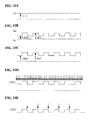
- FIG. 10A illustrates the changes in the current Ia1 consumed in the first A/D converting device 10
- FIG. 10B illustrates the changes in the current Ia2 consumed in the second A/D converting device 20
- FIG. 10C illustrates the changes in the total current Ia consumed, wherein the current Ia1 consumed by the first A/D converting device 10 and the current Ia2 consumed of the second A/D converting device 20 are added together
- FIG. 10D illustrates the changes in the A/D conversion value CNT1 of the first A/D converting device 10
- FIG. 10E illustrates the changes in the A/D conversion value CNT2 of the second A/D converting device 20.
- the currents consumed during the A/D conversion operations of the A/D converting devices 10 and 20 are 1 mA, where the currents consumed when in the A/D conversion operation standby (when in the standby state) are 0.5 mA.
- the total current Ia consumed during the conversion operation of the A/D converting device 20 will be 2 mA, and the total current Ia consumed during the A/D conversion operation standby of the A/D converting device 20 will be 1.5 mA, so the power supply voltage Vcc will fluctuate, causing the A/D conversion value CNT1 of the first A/D converting device 10 to fluctuate.
- the processing device 60 samples the A/D conversion value CNT1 over a short period (that is, at high speed), and thus the fluctuations of the A/D conversion value CNT1 of the first A/D converting device 10 will be captured as-is. This makes it impossible to obtain a stable A/D conversion value CNT1.
- the A/D conversion value CNT2 of the second A/D converting device 20 is sampled intermittently for the value near the completion of the A/D conversion, that is, is sampled at the point in time at which the total current Ia consumed has stabilized, and thus there is no problem because a stabilized A/D conversion value CNT2 is captured by the processing device 60.
- the present invention is to solve this type of problem, and thus the object thereof is to provide a measuring device capable of obtaining stabilized A/D conversion values from both A/D converting devices, wherein there is a common power supply voltage, when sampling A/D conversion values at a short period for one of the A/D converting devices and a long period for the other A/D converting device.
- the invention as set forth in Claim 1 comprises: a first A/D converting device, which receives the supply of a power supply voltage and is in a constantly operating state, for converting an inputted analog signal into a digital signal; a second A/D converting device, which receives a common power supply voltage, with the power supply voltage to the first A/D converting device being the common power supply voltage, to be in a constantly operating state, for converting an inputted analog signal into a digital signal; and a processing device for sampling, with a first period, an A/D converted value that has been converted into a digital signal by the first A/D converting device, and for sampling, with a second period that is longer than the first period, an A/D conversion value that has been converted into a digital signal in the second A/D converting device.
- both the first A/D converting device and the second A/D converting device are always in the operating state, causing the total current consumed, which is the combination of the current consumed by the first A/D converting device and the current consumed by the second A/D converting device, to be constant.
- This makes it possible to obtain stabilized A/D conversion values from both of the A/D converting devices by reducing the fluctuations in the A/D conversion values of the first A/D converting device by stabilizing the power supply voltage.
- the invention as set forth in Claim 2 comprises: a differential pressure sensor for sensing a pressure differential between fluids; an environment sensor for sensing a physical quantity that indicates a change in an environment that has an effect on the differential pressure sensed by the differential pressure sensor; a first A/D converting device, which receives the supply of a power supply voltage and is in a constantly operating state, for converting an inputted analog signal from the differential pressure sensor into a digital signal; a second A/D converting device, which receives a common power supply voltage, with the power supply voltage to the first A/D converting device being the common power supply voltage, to be in a constantly operating state, for converting an inputted analog signal from the environment sensor into a digital signal; and a processing device for sampling, with a first period, an A/D converted value that has been converted into a digital signal by the first A/D converting device, and for sampling, with a second period that is longer than the first period, an A/D conversion value that has been converted into a digital signal in the second A/
- both the first A/D converting device and the second A/D converting device are always in the operating state, causing the total current consumed, which is the combination of the current consumed by the first A/D converting device and the current consumed by the second A/D converting device, to be constant.
- This makes it possible to obtain stabilized A/D conversion values from both of the A/D converting devices by reducing the fluctuations in the A/D conversion values of the first A/D converting device by stabilizing the power supply voltage, making it possible to obtain a precise and stable measured value for a differential pressure by correcting the pressure differential of the fluid, sensed by the differential pressure sensor, using the physical quantity that indicates the change in the environment that has an impact on the sensed pressure differential.
- the invention as set forth in Claim 3 comprises: a differential pressure sensor for sensing a pressure differential between fluids; a plurality of environment sensors for sensing physical quantities that indicates changes in an environment that has an effect on the differential pressure sensed by the differential pressure sensor; a first A/D converting device, which receives the supply of a power supply voltage and is in a constantly operating state, for converting an inputted analog signal from the differential pressure sensor into a digital signal; a second A/D converting device, which receives a common power supply voltage, with the power supply voltage to the first A/D converting device being the common power supply voltage, to be in a constantly operating state, for converting, into digital signals, inputted analog signals that are in accordance with physical quantities sensed by the plurality of environment sensors; and a processing device for sampling, with a first period, an A/D converted value that has been converted into a digital signal by the first A/D converting device, and for sampling, with a second period that is longer than the first period, an A/D conversion value that has
- both the first A/D converting device and the second A/D converting device are always in the operating state, causing the total current consumed, which is the combination of the current consumed by the first A/D converting device and the current consumed by the second A/D converting device, to be constant.
- This makes it possible to obtain stabilized A/D conversion values from both of the A/D converting devices by reducing the fluctuations in the A/D conversion values of the first A/D converting device by stabilizing the power supply voltage, making it possible to obtain a precise and stable measured value for a differential pressure by correcting the pressure differential of the fluid, sensed by the differential pressure sensor, using the plurality of physical quantities that indicates the change in the environment that has an impact on the sensed pressure differential.
- the invention as set forth in Claim 4 comprises: a differential pressure sensor for sensing a pressure differential between fluids; a plurality of environment sensors for sensing physical quantities that indicates changes in an environment that has an effect on the differential pressure sensed by the differential pressure sensor; a first A/D converting device, which receives the supply of a power supply voltage and is in a constantly operating state, for converting an inputted analog signal from the differential pressure sensor into a digital signal; a plurality of second A/D converting devices, each receiving a common power supply voltage, with the power supply voltage to the first A/D converting device being the common power supply voltage, to be in a constantly operating state, for converting, into respective digital signals, respective inputted analog signals that are in accordance with physical quantities sensed by the plurality of environment sensors; and a processing device for sampling, with a first period, an A/D converted value that has been converted into a digital signal by the first A/D converting device, and for sampling, with a second period that is longer than the first period, A/D conversion
- both the first A/D converting device and the second A/D converting device are always in the operating state, causing the total current consumed, which is the combination of the current consumed by the first A/D converting device and the currents consumed by the plurality of second A/D converting devices, to be constant.
- This makes it possible to obtain stabilized A/D conversion values from both of the A/D converting devices by reducing the fluctuations in the A/D conversion values of the first A/D converting device by stabilizing the power supply voltage, making it possible to obtain a precise and stable measured value for a differential pressure by correcting the pressure differential of the fluid, sensed by the differential pressure sensor, using the plurality of physical quantities that indicates the change in the environment that has an impact on the sensed pressure differential.
- the invention as set forth in Claim 5 comprises: a differential pressure sensor for sensing a pressure differential between fluids; a plurality of environment sensors for sensing physical quantities that indicates changes in an environment that has an effect on the differential pressure sensed by the differential pressure sensor; a first A/D converting device, which receives the supply of a power supply voltage and is in a constantly operating state, for converting an inputted analog signal from the differential pressure sensor into a digital signal; a plurality of second A/D converting devices, each receiving a common power supply voltage, with the power supply voltage to the first A/D converting device being the common power supply voltage, to be in intermittent operating states wherein the schedules combine so that the total value for the sum of the currents consumed thereby will be a constant value, for converting, into respective digital signals, respective inputted analog signals that are in accordance with physical quantities sensed by the plurality of environment sensors; and a processing device for sampling, with a first period, an A/D converted value that has been converted into a digital signal by the first A/D
- the first A/D converting device is always in the operating state and the second A/D converting devices are in intermittent operating states wherein the schedules combine so that the total value for the sum of the currents consumed thereby will be a constant value, causing the total current consumed, which is the combination of the current consumed by the first A/D converting device and the currents consumed by the plurality of second A/D converting devices, to be constant.
- the first A/D converting device and the second A/D converting device are placed into the constantly operating state, or the first A/D converting device and all of the second A/D converting devices are placed into the constantly operating state, or the first A/D converting device is placed into the constantly operating state and the plurality of second A/D converting devices are placed into intermittent operating states wherein the schedules combine so that the total value for the sum of the currents consumed thereby will be a constant value, to stabilize the power supply voltage by causing the total current consumed, which is the sum of the current consumed by the first A/D converting device and the current consumed by second A/D converting device (or the currents consumed by the plurality of second A/D converting devices), to be a constant value, to reduce the fluctuations in the A/D conversion value from the first A/D converting device that performs sampling with a short period, making it possible to obtain stabilized A/D conversion values from all of the A/D converting devices.
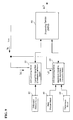
- FIG. 1 is a diagram illustrating the components in a differential pressure transmitting device that is one example of a measuring device according to the present invention.
- 1 is a first A/D converting device
- 2 is a second A/D converting device
- 3 is a differential pressure sensor
- 4 is a static pressure sensor
- 5 is a temperature sensor
- 6 is a processing device, corresponding to the first A/D converting device 10, the second A/D converting device 20, the differential pressure sensor 30, the static pressure sensor 40, the temperature sensor 50, and the processing device 60 in the differential pressure transmitting device illustrated in FIG. 9 .
- the A/D converting device 10 is in a constantly operating state (a continuous converting mode), and the A/D converting device 20 is in an intermittently operating state (an intermittent converting mode), but in the present example, both the A/D converting device 1 and the A/D converting device 2 are in the constantly operating state (the continuous converting mode).
- the continuous converting mode may be set individually to the A/D converting device 1 and the A/D converting device 2 at the time of shipment from the factory, or instructions may be applied individually by the processing device 6.
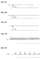
- FIG. 2A illustrates the changes in the current Ia1 consumed by the first A/D converting device 1
- FIG. 2B illustrates the changes in the current Ia2 consumed by the second A/D converting device 2
- FIG. 2C illustrates the changes in the total current Ia consumed by the combination of the current Ia1 consumed by the first A/D converting device 1 and the current Ia2 consumed by the second A/D converting device 2
- FIG. 2D illustrates the changes in the A/D conversion value CNT1 of the first A/D converting device 1
- in figure 2E illustrates the changes in the A/D conversion value CNT2 by the second A/D converting device 2.
- the currents consumed during the A/D conversion operations (when in an operating state) of the A/D converting devices 1 and 2 are each 1 mA.
- the power supply voltage Vcc will be stabilized, decreasing the fluctuations in the A/D conversion value CNT1 by the A/D converting device 1, as illustrated in FIG. 2D .
- the A/D conversion value CNT2 of the second A/D converting device 2 will also be obtained continuously, and there will also be no fluctuations in the A/D conversion value CNT2 of the second A/D converting device 2.
- the processing device 6 samples the A/D conversion value CNT1 with a short period, and samples the A/D conversion value CNT2 with a long period. In this case, the fluctuations in the A/D conversion value CNT1 of the A/D converting device 1 are reduced, thus making it possible for a stabilized A/D conversion value CNT1 to be obtained by the processing device 6. Additionally, because no fluctuations are produced in the A/D conversion value CNT2 of the A/D converting device 2 either, and because the values near to the completion of the A/D conversion by the A/D converting device 2 are sampled, a stabilized A/D conversion value CNT2 can be obtained by the processing device 6.
- a stabilized A/D conversion value can be obtained from either of the A/D converting devices, and the pressure differential of the fluids sensed by the differential pressure sensor 3 are corrected by the static pressure from the static pressure sensor 4 and by the temperature from the temperature sensor 5, thus making it possible to calculate a precise and stabilized measured value ⁇ P for the differential pressure.
- an electric signal in accordance with the static pressure from the pressure sensor 4 and an electric signal in accordance with the temperature from the temperature sensor 5 are applied to the A/D converting device 2
- the electric signal in accordance with the static pressure from the static pressure sensor 4 alone may be applied to the A/D converting device 2
- the electric signal in accordance with the temperature from the temperature sensor 5 alone may be applied to the A/D converting device 2. That is, the differential pressure may be corrected for the static pressure alone, or the differential pressure may be corrected for the temperature alone.
- the physical quantity that indicates the change in the environment that effects the pressure differential sensed by the differential pressure sensor 3 is not limited to static pressure or temperature.
- an electric signal in accordance with the humidity may also be applied to the A/D converting device 2.
- the electric signal in accordance with the static pressure, from the differential pressure sensor 4, and the electric signal in accordance with the temperature, from the temperature sensor 5, are applied to a single A/D converting device 2, instead, as illustrated in FIG. 3 , there may be two second A/D converting devices, an A/D converting device 2-1A and an A/D converting device 2-2A, where an electric signal in accordance with the static pressure is applied from the static pressure sensor 4 to the A/D converting device 2-1A, and an electric signal in accordance with the temperature from the temperature sensor 5 may be applied to the A/D converting device 2-2A.
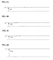
- the total current Ia consumed which is the combination of the current Ia1 consumed of the first A/D converting device 1 and the currents Ia2 and Ia3 consumed of the second A/D converting devices 2-1A and 2-2A, will always be a constant value (as illustrated in FIG. 4A through FIG. 4D ), enabling stabilized A/D conversion values to be obtained from all of the A/D converting devices.
- the total current consumed Ia which is the combination of the current Ia1 consumed by the first A/D converting device and the currents Ia2 and Ia3 consumed by the second A/D converting devices 2-1B and 2-2B, may be caused to be uniform by having the first A/D converting device 1 be in a constantly operating state and the second A/D converting devices 2-1B and 2-2B be in intermittently operating states wherein the schedules are combined so that the total value for the currents Ia2 and Ia3 consumed will be constant.
- FIG. 6A through FIG. 6D illustrate timing charts for the intermittent operating statuses of the second A/D converting devices 2-1B and 2-2B, with the combined schedule.
- Such a schedule may be set by the processing device 6 into the A/D converting devices 2-1B and 2-2B, or may be set into the A/D converting devices 2-1B and 2-2B at the time of shipping from the factory.
- the total current Ia consumed when all three of the A/D converting devices are in the constantly operating state would be 3 mA in this example, the total current consumed Ia can be reduced to 2.5 mA, reducing the current consumption.
- FIG. 7 illustrates an example wherein the second A/D converting device is divided into three A/D converting devices: the A/D converting device 2-1C, the A/D converting device 2-2C, and the A/D converting device 2-3C, wherein an electric signal in accordance with the static pressure is applied from the static pressure sensor 4 to the A/D converting device 2-1C, an electric signal in accordance with the temperature is applied from the temperature sensor 5 to the A/D converting device 2-2C, and an electric signal in accordance with the humidity is applied from a humidity sensor 7 to the A/D converting device 2-3C.
- the second A/D converting devices 2-1C, 2-2C, and 2-3C wherein the schedules are combined so that the total value for the currents Ia2, Ia3, and Ia4 will be a constant value, making it possible to cause the total current Ia consumed, which is the combination of the current Ia1 consumed by the first A/D converting device 1, and the currents Ia2, Ia3, and Ia4 consumed by the second A/D converting devices 2-1C, 2-2C, and 2-2AD, to be a constant value.
- FIG. 8A through FIG. 8E illustrate timing charts for the intermittent operating statuses of the second A/D converting devices 2-1, 2-2, and 2-3, with the combined schedule.
- Such a schedule may be set by the processing device 6 into the A/D converting devices 2-1C, 2-2C, and 2-3C, or may be set into the A/D converting devices 2-1C, 2-2C, and 2-3C at the time of shipping from the factory.
- the total current Ia consumed when all four of the A/D converting devices are in the constantly operating state would be 4 mA in this example, the total current consumed Ia can be reduced to 3 mA, reducing the current consumption.
- the measuring device is not limited to a differential pressure transmitting device, but rather may be applied to various types of measuring devices that use a plurality of A/D converting devices in the same manner.
- the measuring device according to the present invention can be used in a variety of fields, such as in process control.
Landscapes
- Physics & Mathematics (AREA)
- General Physics & Mathematics (AREA)
- Measuring Fluid Pressure (AREA)
- Arrangements For Transmission Of Measured Signals (AREA)
Abstract
Description
- The present invention relates to a measuring device, such as a differential pressure transmitting device.
- Conventionally differential pressure transmitting devices have been used as devices for sensing and transmitting differential pressures of fluids. (See, for example, Patent Reference 1 (Japanese Unexamined Patent Application Publication
H2-88921 - In this differential pressure transmitting device, a fluid pressure Pa is conveyed through a non-compressible fluid (such as silicone oil) to the pressure chamber A, and a fluid pressure Pb is conveyed through a non-compressible fluid (such as silicone oil) to a pressure chamber B. Doing so causes the measuring diaphragm to deform in accordance with | Pa - Pb | towards the side of the pressure chamber having the lower fluid pressure, where the state of deformation of the measuring diaphragm is sensed by a strain gauge to produce an electric signal (an analog signal) in accordance with the differential pressure by a converting device, where the electric signal thus produced is sent to an A/D converting device to convert to a digital signal.
- The processing device samples the A/D conversion value that has been converted into the digital signal by the A/D converting device in each specific sampling period, calculates the measured value ΔP for the differential pressure by performing a variety of calculating processes such as a smoothing calculation, a square root calculation, a first-order delay calculation (a damping calculation), or the like, on the sampled A/D conversion value, and outputs the calculated differential pressure measurement value ΔP.
- Additionally, in this differential pressure transmitting device, in order to increase the precision of the measured value ΔP, the static pressure, temperature, and the like are measured as physical quantities that indicate changes in the environment that influence the differential pressure that is sensed by the differential pressure sensor, and corrections are performed on the measured value ΔP for the differential pressure based on the measured static pressure, temperature, or the like. In this case, in the
aforementioned Document 1, a single A/D converting device is used to convert the differential pressure, the static pressure, and the temperature into digital signals, and the A/D conversion values wherein these have been converted into digital signals are sampled. - However, the sampling periods for the static pressure, temperature, or the like, are longer periods than the sampling period for the differential pressure. That is, because the changes in the static pressure, temperature, and the like are more gradual than those for the differential pressure, sampling is performed with a short period for the differential pressure, and sampling is performed with long periods for the static pressure and the temperature.
However, in applications that require high-speed differential pressure measurements, it is not possible to accommodate the increase in speed when sampling the differential pressure, the static pressure, and the temperature with a single A/D converting device. - Given this, the present applicant has thought of achieving an increase in speed of the differential pressure measurements by providing two A/D converting devices, where the differential pressure is sampled with a short period by one A/D converting device, and the static pressure and temperature are sampled with a long period by the other A/D converting device.
FIG. 9 illustrates one example thereof. - In
FIG. 9 :10 is a first A/D converting device; 20 is a second A/D converting device; 30 is a differential pressure sensor; 40 is a static pressure sensor; 50 is temperature sensor: and 60 is a processing device (MPU); wherein: an electric signal (an analog signal) in accordance with the differential pressure is applied from the differential pressure sensor to be the first A/D converting device; an electric signal (an analog signal) in accordance with the static pressure is applied by thestatic pressure sensor 40 and an electric signal (an analog signal) in accordance with the temperature is applied from thetemperature sensor 50, to the second A/D converting device 20. - The first A/
D converting device 10 converts the electric signal in accordance with the differential pressure from thedifferential pressure sensor 30 into a digital signal. The second A/D converting device 20 converts the analog signal in accordance with the static pressure from thestatic pressure sensor 40, and the analog signal in accordance with the temperature from thetemperature sensor 50, into digital signals. - The
processing device 60 samples, with a short period, the A/D conversion value that has been converted into a digital signal by the first A/D converting device 10, samples, with a long period, the A/D conversion values that have been converted into digital signals by the second A/D converting device 20, and calculates a measured value ΔP for the differential pressure based on the A/D conversion values sampled from the first A/D converting device 10 and the A/D conversion values sampled from the second A/D converting device 20. - In this differential pressure transmitting device, a common power supply voltage Vcc is applied to both the A/
D converting devices D converting device 10 is put into a constantly operating mode (a continuous converting mode) and the A/D converting device 20 is put into an intermittent operating mode (an intermittent converting mode). That is, the A/D converting device 10 performs sampling with a short period, and this is constantly performing the A/D converting operation. In contrast, the A/D converting device 20 performs sampling with a long period, and thus, for the purposes of reducing the electric current consumed, performs the A/D conversion operations intermittently, and goes into a standby state when not performing the A/D conversion operation. - However, in this method, the power supply voltage Vcc will vary because while the A/
D converting device 10 is in a constantly operating state, the A/D converting device 20 is in an intermittently operating state, producing a problem in that it is not possible to obtain stable A/D conversion values. This problem will be explained referencing the timing charts illustrated inFIG. 10A through FIG. 10E . -
FIG. 10A illustrates the changes in the current Ia1 consumed in the first A/D converting device 10;FIG. 10B illustrates the changes in the current Ia2 consumed in the second A/D converting device 20;FIG. 10C illustrates the changes in the total current Ia consumed, wherein the current Ia1 consumed by the first A/D converting device 10 and the current Ia2 consumed of the second A/D converting device 20 are added together;FIG. 10D illustrates the changes in the A/D conversion value CNT1 of the first A/D converting device 10; andFIG. 10E illustrates the changes in the A/D conversion value CNT2 of the second A/D converting device 20. In the present example, the currents consumed during the A/D conversion operations of the A/D converting devices 10 and 20 (when in an operating state) are 1 mA, where the currents consumed when in the A/D conversion operation standby (when in the standby state) are 0.5 mA. - In this case, the total current Ia consumed during the conversion operation of the A/
D converting device 20 will be 2 mA, and the total current Ia consumed during the A/D conversion operation standby of the A/D converting device 20 will be 1.5 mA, so the power supply voltage Vcc will fluctuate, causing the A/D conversion value CNT1 of the first A/D converting device 10 to fluctuate. Theprocessing device 60 samples the A/D conversion value CNT1 over a short period (that is, at high speed), and thus the fluctuations of the A/D conversion value CNT1 of the first A/D converting device 10 will be captured as-is. This makes it impossible to obtain a stable A/D conversion value CNT1. - Note that the A/D conversion value CNT2 of the second A/
D converting device 20 is sampled intermittently for the value near the completion of the A/D conversion, that is, is sampled at the point in time at which the total current Ia consumed has stabilized, and thus there is no problem because a stabilized A/D conversion value CNT2 is captured by theprocessing device 60. - The present invention is to solve this type of problem, and thus the object thereof is to provide a measuring device capable of obtaining stabilized A/D conversion values from both A/D converting devices, wherein there is a common power supply voltage, when sampling A/D conversion values at a short period for one of the A/D converting devices and a long period for the other A/D converting device.
- In order to achieve this object, the invention as set forth in
Claim 1 comprises: a first A/D converting device, which receives the supply of a power supply voltage and is in a constantly operating state, for converting an inputted analog signal into a digital signal; a second A/D converting device, which receives a common power supply voltage, with the power supply voltage to the first A/D converting device being the common power supply voltage, to be in a constantly operating state, for converting an inputted analog signal into a digital signal; and a processing device for sampling, with a first period, an A/D converted value that has been converted into a digital signal by the first A/D converting device, and for sampling, with a second period that is longer than the first period, an A/D conversion value that has been converted into a digital signal in the second A/D converting device. - Given the present invention, both the first A/D converting device and the second A/D converting device are always in the operating state, causing the total current consumed, which is the combination of the current consumed by the first A/D converting device and the current consumed by the second A/D converting device, to be constant. This makes it possible to obtain stabilized A/D conversion values from both of the A/D converting devices by reducing the fluctuations in the A/D conversion values of the first A/D converting device by stabilizing the power supply voltage.
- The invention as set forth in
Claim 2 comprises: a differential pressure sensor for sensing a pressure differential between fluids; an environment sensor for sensing a physical quantity that indicates a change in an environment that has an effect on the differential pressure sensed by the differential pressure sensor; a first A/D converting device, which receives the supply of a power supply voltage and is in a constantly operating state, for converting an inputted analog signal from the differential pressure sensor into a digital signal; a second A/D converting device, which receives a common power supply voltage, with the power supply voltage to the first A/D converting device being the common power supply voltage, to be in a constantly operating state, for converting an inputted analog signal from the environment sensor into a digital signal; and a processing device for sampling, with a first period, an A/D converted value that has been converted into a digital signal by the first A/D converting device, and for sampling, with a second period that is longer than the first period, an A/D conversion value that has been converted into a digital signal in the second A/D converting device. - Given the present invention, both the first A/D converting device and the second A/D converting device are always in the operating state, causing the total current consumed, which is the combination of the current consumed by the first A/D converting device and the current consumed by the second A/D converting device, to be constant. This makes it possible to obtain stabilized A/D conversion values from both of the A/D converting devices by reducing the fluctuations in the A/D conversion values of the first A/D converting device by stabilizing the power supply voltage, making it possible to obtain a precise and stable measured value for a differential pressure by correcting the pressure differential of the fluid, sensed by the differential pressure sensor, using the physical quantity that indicates the change in the environment that has an impact on the sensed pressure differential.
- The invention as set forth in
Claim 3 comprises: a differential pressure sensor for sensing a pressure differential between fluids; a plurality of environment sensors for sensing physical quantities that indicates changes in an environment that has an effect on the differential pressure sensed by the differential pressure sensor; a first A/D converting device, which receives the supply of a power supply voltage and is in a constantly operating state, for converting an inputted analog signal from the differential pressure sensor into a digital signal; a second A/D converting device, which receives a common power supply voltage, with the power supply voltage to the first A/D converting device being the common power supply voltage, to be in a constantly operating state, for converting, into digital signals, inputted analog signals that are in accordance with physical quantities sensed by the plurality of environment sensors; and a processing device for sampling, with a first period, an A/D converted value that has been converted into a digital signal by the first A/D converting device, and for sampling, with a second period that is longer than the first period, an A/D conversion value that has been converted into a digital signal in the second A/D converting device. - Given the present invention, both the first A/D converting device and the second A/D converting device are always in the operating state, causing the total current consumed, which is the combination of the current consumed by the first A/D converting device and the current consumed by the second A/D converting device, to be constant. This makes it possible to obtain stabilized A/D conversion values from both of the A/D converting devices by reducing the fluctuations in the A/D conversion values of the first A/D converting device by stabilizing the power supply voltage, making it possible to obtain a precise and stable measured value for a differential pressure by correcting the pressure differential of the fluid, sensed by the differential pressure sensor, using the plurality of physical quantities that indicates the change in the environment that has an impact on the sensed pressure differential.
- The invention as set forth in
Claim 4 comprises: a differential pressure sensor for sensing a pressure differential between fluids; a plurality of environment sensors for sensing physical quantities that indicates changes in an environment that has an effect on the differential pressure sensed by the differential pressure sensor; a first A/D converting device, which receives the supply of a power supply voltage and is in a constantly operating state, for converting an inputted analog signal from the differential pressure sensor into a digital signal; a plurality of second A/D converting devices, each receiving a common power supply voltage, with the power supply voltage to the first A/D converting device being the common power supply voltage, to be in a constantly operating state, for converting, into respective digital signals, respective inputted analog signals that are in accordance with physical quantities sensed by the plurality of environment sensors; and a processing device for sampling, with a first period, an A/D converted value that has been converted into a digital signal by the first A/D converting device, and for sampling, with a second period that is longer than the first period, A/D conversion values that have been converted into digital signals in the plurality of second A/D converting devices. - Given the present invention, both the first A/D converting device and the second A/D converting device are always in the operating state, causing the total current consumed, which is the combination of the current consumed by the first A/D converting device and the currents consumed by the plurality of second A/D converting devices, to be constant. This makes it possible to obtain stabilized A/D conversion values from both of the A/D converting devices by reducing the fluctuations in the A/D conversion values of the first A/D converting device by stabilizing the power supply voltage, making it possible to obtain a precise and stable measured value for a differential pressure by correcting the pressure differential of the fluid, sensed by the differential pressure sensor, using the plurality of physical quantities that indicates the change in the environment that has an impact on the sensed pressure differential.
- The invention as set forth in
Claim 5 comprises: a differential pressure sensor for sensing a pressure differential between fluids; a plurality of environment sensors for sensing physical quantities that indicates changes in an environment that has an effect on the differential pressure sensed by the differential pressure sensor; a first A/D converting device, which receives the supply of a power supply voltage and is in a constantly operating state, for converting an inputted analog signal from the differential pressure sensor into a digital signal; a plurality of second A/D converting devices, each receiving a common power supply voltage, with the power supply voltage to the first A/D converting device being the common power supply voltage, to be in intermittent operating states wherein the schedules combine so that the total value for the sum of the currents consumed thereby will be a constant value, for converting, into respective digital signals, respective inputted analog signals that are in accordance with physical quantities sensed by the plurality of environment sensors; and a processing device for sampling, with a first period, an A/D converted value that has been converted into a digital signal by the first A/D converting device, and for sampling, with a second period that is longer than the first period, A/D conversion values that have been converted into digital signals in the plurality of second A/D converting devices. - Given the present invention, the first A/D converting device is always in the operating state and the second A/D converting devices are in intermittent operating states wherein the schedules combine so that the total value for the sum of the currents consumed thereby will be a constant value, causing the total current consumed, which is the combination of the current consumed by the first A/D converting device and the currents consumed by the plurality of second A/D converting devices, to be constant. This makes it possible to obtain stabilized AID conversion values from both of the A/D converting devices by reducing the fluctuations in the A/D conversion values of the first A/D converting device by stabilizing the power supply voltage, making it possible to obtain a precise and stable measured value for a differential pressure by correcting the pressure differential of the fluid, sensed by the differential pressure sensor, using the plurality of physical quantities that indicates the change in the environment that has an impact on the sensed pressure differential.
- In the present invention, the first A/D converting device and the second A/D converting device are placed into the constantly operating state, or the first A/D converting device and all of the second A/D converting devices are placed into the constantly operating state, or the first A/D converting device is placed into the constantly operating state and the plurality of second A/D converting devices are placed into intermittent operating states wherein the schedules combine so that the total value for the sum of the currents consumed thereby will be a constant value, to stabilize the power supply voltage by causing the total current consumed, which is the sum of the current consumed by the first A/D converting device and the current consumed by second A/D converting device (or the currents consumed by the plurality of second A/D converting devices), to be a constant value, to reduce the fluctuations in the A/D conversion value from the first A/D converting device that performs sampling with a short period, making it possible to obtain stabilized A/D conversion values from all of the A/D converting devices.
-
-
FIG. 1 is a diagram illustrating the critical components of a differential pressure transmitting device that is one example of a measuring device according to the present invention. -
FIG. 2A is a diagram illustrating the changes in the current Ia1 consumed by a first A/D converting device in the differential pressure transmitting device illustrated inFIG. 1 . -
FIG. 2B is a diagram illustrating the changes in the current Ia2 consumed by a second A/D converting device in the differential pressure transmitting device illustrated inFIG. 1 . -
FIG. 2C is a diagram illustrating the changes in the total current Ia consumed that is the sum of the current Ia1 consumed by a first A/D converting device and the current Ia2 consumed by the second A/D converting device in the differential pressure transmitting device illustrated inFIG. 1 . -
FIG. 2D is a diagram illustrating the changes in the A/D conversion value CNT1 by a first A/D converting device in the differential pressure transmitting device illustrated inFIG. 1 . -
FIG. 2E is a diagram illustrating the changes in the A/D conversion value CNT2 by a second A/D converting device in the differential pressure transmitting device illustrated inFIG. 1 . -
FIG. 3 is a diagram illustrating an example wherein two A/D converting devices are provided as the second A/D converting device, and wherein the first A/D converting device and the second A/D converting devices are in the constantly operating state. -
FIG. 4A is a diagram illustrating the changes in the current Ia1 consumed by a first A/D converting device in the differential pressure transmitting device illustrated inFIG. 3 . -
FIG. 4B is a diagram illustrating the changes in a current Ia2 consumed by a second A/D converting device in the differential pressure transmitting device illustrated inFIG. 3 . -
FIG. 4C is a diagram illustrating the changes in a current Ia3 consumed by a second A/D converting device in the differential pressure transmitting device illustrated inFIG. 3 . -
FIG. 4D is a diagram illustrating the changes in the total current Ia consumed that is the sum of the current Ia1 consumed by a first A/D converting device and the currents Ia2 and Ia3 consumed by the second A/D converting devices in the differential pressure transmitting device illustrated inFIG. 3 . -
FIG. 5 is a diagram illustrating an example wherein two A/D converting devices are provided as the second A/D converting device, wherein the first A/D converting device is in the constantly operating state, and the second A/D converting devices are in intermittent operating states with a combined schedule. -
FIG. 6A is a diagram illustrating the changes in the current Ia1 consumed by a first A/D converting device in the differential pressure transmitting device illustrated inFIG. 5 . -
FIG. 6B is a diagram illustrating the changes in a current Ia2 consumed by a second A/D converting device in the differential pressure transmitting device illustrated inFIG. 5 . -
FIG. 6C is a diagram illustrating the changes in a current Ia3 consumed by a second A/D converting device in the differential pressure transmitting device illustrated inFIG. 5 . -
FIG. 6D is a diagram illustrating the changes in the total current Ia consumed that is the sum of the current Ia1 consumed by a first A/D converting device and the currents Ia2 and Ia3 consumed by the second A/D converting devices in the differential pressure transmitting device illustrated inFIG. 5 . -
FIG. 7 is a diagram illustrating an example wherein three A/D converting devices are provided as the second A/D converting device, wherein the first A/D converting device is in the constantly operating state, and the second A/D converting devices are in intermittent operating states with a combined schedule. -
FIG. 8A is a diagram illustrating the changes in the current Ia1 consumed by a first A/D converting device in the differential pressure transmitting device illustrated inFIG. 7 . -
FIG. 8B is a diagram illustrating the changes in a current Ia2 consumed by a second A/D converting device in the differential pressure transmitting device illustrated inFIG. 7 . -
FIG. 8C is a diagram illustrating the changes in a current Ia3 consumed by a second A/D converting device in the differential pressure transmitting device illustrated inFIG. 7 . -
FIG. 8D is a diagram illustrating the changes in a current Ia4 consumed by a second A/D converting device in the differential pressure transmitting device illustrated inFIG. 7 . -
FIG. 8E is a diagram illustrating the changes in the total current Ia consumed that is the sum of the current Ia1 consumed by a first A/D converting device and the currents Ia2, Ia3, and Ia4 consumed by the second A/D converting devices in the differential pressure transmitting device illustrated inFIG. 7 . -
FIG. 9 is a diagram illustrating the critical components of a differential pressure transmitting device contemplated by the present inventors as a prerequisite technology prior to arriving at the present invention. -
FIG. 10A is a diagram illustrating the changes in the current Ia1 consumed by a first A/D converting device in the differential pressure transmitting device illustrated inFIG. 9 . -
FIG. 10B is a diagram illustrating the changes in a current Ia2 consumed by a second A/D converting device in the differential pressure transmitting device illustrated inFIG. 9 . -
FIG. 10C is a diagram illustrating the changes in the total current Ia consumed that is the sum of the current Ia1 consumed by a first A/D converting device and the current Ia2 consumed by the second A/D converting device in the differential pressure transmitting device illustrated inFIG. 9 . -
FIG. 10D is a diagram illustrating the changes in the A/D conversion value CNT1 by a first A/D converting device in the differential pressure transmitting device illustrated inFIG. 9 . -
FIG. 10E is a diagram illustrating the changes in the A/D conversion value CNT2 by a second A/D converting device in the differential pressure transmitting device illustrated inFIG. 9 . - The present invention will be described in detail based on the drawings, below.
FIG. 1 is a diagram illustrating the components in a differential pressure transmitting device that is one example of a measuring device according to the present invention. In thefigure, 1 is a first A/D converting device, 2 is a second A/D converting device, 3 is a differential pressure sensor, 4 is a static pressure sensor, 5 is a temperature sensor, and 6 is a processing device, corresponding to the first A/D converting device 10, the second A/D converting device 20, thedifferential pressure sensor 30, thestatic pressure sensor 40, thetemperature sensor 50, and theprocessing device 60 in the differential pressure transmitting device illustrated inFIG. 9 . - In the differential pressure transmitting device illustrated in
FIG. 9 , the A/D converting device 10 is in a constantly operating state (a continuous converting mode), and the A/D converting device 20 is in an intermittently operating state (an intermittent converting mode), but in the present example, both the A/D converting device 1 and the A/D converting device 2 are in the constantly operating state (the continuous converting mode). - Note that the continuous converting mode may be set individually to the A/
D converting device 1 and the A/D converting device 2 at the time of shipment from the factory, or instructions may be applied individually by the processing device 6. -
FIG. 2A illustrates the changes in the current Ia1 consumed by the first A/D converting device 1;FIG. 2B illustrates the changes in the current Ia2 consumed by the second A/D converting device 2;FIG. 2C illustrates the changes in the total current Ia consumed by the combination of the current Ia1 consumed by the first A/D converting device 1 and the current Ia2 consumed by the second A/D converting device 2;FIG. 2D illustrates the changes in the A/D conversion value CNT1 of the first A/D converting device 1; infigure 2E illustrates the changes in the A/D conversion value CNT2 by the second A/D converting device 2. In this example, the currents consumed during the A/D conversion operations (when in an operating state) of the A/D converting devices - In this case, because both the A/
D converting device 1 and the A/D converting device 2 are in the always operating state, the total current consumed Ia, which is the total of the current consumed Ia1 by the A/D converting device 1 and the current consumed Ia2 by the A/D converting device 2 will be Ia = Ia1+ Ia2 = 1 mA +1 mA = 2 mA, which will always be constant. - As a result, the power supply voltage Vcc will be stabilized, decreasing the fluctuations in the A/D conversion value CNT1 by the A/
D converting device 1, as illustrated inFIG. 2D . Note that, in this case, as illustrated inFIG. 2E , the A/D conversion value CNT2 of the second A/D converting device 2 will also be obtained continuously, and there will also be no fluctuations in the A/D conversion value CNT2 of the second A/D converting device 2. - The processing device 6 samples the A/D conversion value CNT1 with a short period, and samples the A/D conversion value CNT2 with a long period. In this case, the fluctuations in the A/D conversion value CNT1 of the A/
D converting device 1 are reduced, thus making it possible for a stabilized A/D conversion value CNT1 to be obtained by the processing device 6. Additionally, because no fluctuations are produced in the A/D conversion value CNT2 of the A/D converting device 2 either, and because the values near to the completion of the A/D conversion by the A/D converting device 2 are sampled, a stabilized A/D conversion value CNT2 can be obtained by the processing device 6. - In this way, a stabilized A/D conversion value can be obtained from either of the A/D converting devices, and the pressure differential of the fluids sensed by the
differential pressure sensor 3 are corrected by the static pressure from thestatic pressure sensor 4 and by the temperature from thetemperature sensor 5, thus making it possible to calculate a precise and stabilized measured value ΔP for the differential pressure. - Note that while in the present example an electric signal in accordance with the static pressure from the
pressure sensor 4 and an electric signal in accordance with the temperature from thetemperature sensor 5 are applied to the A/D converting device 2, conversely, the electric signal in accordance with the static pressure from thestatic pressure sensor 4 alone may be applied to the A/D converting device 2, or the electric signal in accordance with the temperature from thetemperature sensor 5 alone may be applied to the A/D converting device 2. That is, the differential pressure may be corrected for the static pressure alone, or the differential pressure may be corrected for the temperature alone. - Moreover, the physical quantity that indicates the change in the environment that effects the pressure differential sensed by the
differential pressure sensor 3 is not limited to static pressure or temperature. For example, in addition to static pressure and temperature, an electric signal in accordance with the humidity may also be applied to the A/D converting device 2. - Furthermore, while in the present example of embodiment the electric signal in accordance with the static pressure, from the
differential pressure sensor 4, and the electric signal in accordance with the temperature, from thetemperature sensor 5, are applied to a single A/D converting device 2, instead, as illustrated inFIG. 3 , there may be two second A/D converting devices, an A/D converting device 2-1A and an A/D converting device 2-2A, where an electric signal in accordance with the static pressure is applied from thestatic pressure sensor 4 to the A/D converting device 2-1A, and an electric signal in accordance with the temperature from thetemperature sensor 5 may be applied to the A/D converting device 2-2A. - In this case, if the first A/
D converting device 1 and the second A/D converting devices 2-1A and 2-2A are in the constantly operating state, then the total current Ia consumed, which is the combination of the current Ia1 consumed of the first A/D converting device 1 and the currents Ia2 and Ia3 consumed of the second A/D converting devices 2-1A and 2-2A, will always be a constant value (as illustrated inFIG. 4A through FIG. 4D ), enabling stabilized A/D conversion values to be obtained from all of the A/D converting devices. - Note that, as illustrated in
FIG. 5 , the total current consumed Ia, which is the combination of the current Ia1 consumed by the first A/D converting device and the currents Ia2 and Ia3 consumed by the second A/D converting devices 2-1B and 2-2B, may be caused to be uniform by having the first A/D converting device 1 be in a constantly operating state and the second A/D converting devices 2-1B and 2-2B be in intermittently operating states wherein the schedules are combined so that the total value for the currents Ia2 and Ia3 consumed will be constant. -
FIG. 6A through FIG. 6D illustrate timing charts for the intermittent operating statuses of the second A/D converting devices 2-1B and 2-2B, with the combined schedule. In this example, the second A/D converting devices 2-1B and 2-2B are switched intermittently between the standby state and the operating state so that the interval of the standby state (wherein the current consumption = 0.5 mA) and the interval of the operating state (wherein the current consumption = 1 mA) are overlapped. - Note that such a schedule may be set by the processing device 6 into the A/D converting devices 2-1B and 2-2B, or may be set into the A/D converting devices 2-1B and 2-2B at the time of shipping from the factory.
- Doing so causes the total current Ia consumed that is the combination of the current Ia1 consumed by the first A/
D converting device 1, and the currents Ia2 and Ia3 consumed by the second A/D converting devices 2-1B and 2-2B to be 2.5 mA, to be a constant value. - While the total current Ia consumed when all three of the A/D converting devices are in the constantly operating state would be 3 mA in this example, the total current consumed Ia can be reduced to 2.5 mA, reducing the current consumption.
-
FIG. 7 illustrates an example wherein the second A/D converting device is divided into three A/D converting devices: the A/D converting device 2-1C, the A/D converting device 2-2C, and the A/D converting device 2-3C, wherein an electric signal in accordance with the static pressure is applied from thestatic pressure sensor 4 to the A/D converting device 2-1C, an electric signal in accordance with the temperature is applied from thetemperature sensor 5 to the A/D converting device 2-2C, and an electric signal in accordance with the humidity is applied from ahumidity sensor 7 to the A/D converting device 2-3C. - In this case as well, while the first A/
D converting device 1 is in the constantly operating state, the second A/D converting devices 2-1C, 2-2C, and 2-3C, wherein the schedules are combined so that the total value for the currents Ia2, Ia3, and Ia4 will be a constant value, making it possible to cause the total current Ia consumed, which is the combination of the current Ia1 consumed by the first A/D converting device 1, and the currents Ia2, Ia3, and Ia4 consumed by the second A/D converting devices 2-1C, 2-2C, and 2-2AD, to be a constant value. -
FIG. 8A through FIG. 8E illustrate timing charts for the intermittent operating statuses of the second A/D converting devices 2-1, 2-2, and 2-3, with the combined schedule. In this example, the second A/D converting devices 2-1C, 2-2C, and 2-3C are switched intermittently between the standby state and the operating state so that the interval of the standby state of two of the A/D converting devices (wherein the current consumption = 0.5 mA) and the interval of the operating state of one of the A/D converting devices (wherein the current consumption = 1 mA) are overlapped. - Note that such a schedule may be set by the processing device 6 into the A/D converting devices 2-1C, 2-2C, and 2-3C, or may be set into the A/D converting devices 2-1C, 2-2C, and 2-3C at the time of shipping from the factory.
- Doing so causes the total current Ia consumed that is the combination of the current Ia1 consumed by the first A/
D converting device 1, and the currents Ia2, Ia3, and Ia4 consumed by the second A/D converting devices 2-1C, 2-2C, and 2-3C to be 3 mA, to be a constant value. - While the total current Ia consumed when all four of the A/D converting devices are in the constantly operating state would be 4 mA in this example, the total current consumed Ia can be reduced to 3 mA, reducing the current consumption.
- Note that while in the example of embodiment set forth above the explanation was for the case of a differential pressure transmitting device as one example of a measuring device, the measuring device is not limited to a differential pressure transmitting device, but rather may be applied to various types of measuring devices that use a plurality of A/D converting devices in the same manner.
- The measuring device according to the present invention can be used in a variety of fields, such as in process control.
Claims (5)
- A measuring instrument comprising:a first A/D converting device, which receives the supply of a power supply voltage and is in a constantly operating state, for converting an inputted analog signal into a digital signal;a second A/D converting device, which receives a common power supply voltage, with the power supply voltage to the first A/D converting device being the common power supply voltage, to be in a constantly operating state, for converting an inputted analog signal into a digital signal; anda processing device for sampling, with a first period, an A/D converted value that has been converted into a digital signal by the first A/D converting device, and for sampling, with a second period that is longer than the first period, an A/D conversion value that has been converted into a digital signal in the second A/D converting device.
- A measuring instrument comprising:a differential pressure sensor for sensing a pressure differential between fluids;an environment sensor for sensing a physical quantity that indicates a change in an environment that has an effect on the differential pressure sensed by the differential pressure sensor;a first A/D converting device, which receives the supply of a power supply voltage and is in a constantly operating state, for converting an inputted analog signal from the differential pressure sensor into a digital signal;a second A/D converting device, which receives a common power supply voltage, with the power supply voltage to the first A/D converting device being the common power supply voltage, to be in a constantly operating state, for converting an inputted analog signal from the environment sensor into a digital signal; anda processing device for sampling, with a first period, an A/D converted value that has been converted into a digital signal by the first A/D converting device, and for sampling, with a second period that is longer than the first period, an A/D conversion value that has been converted into a digital signal in the second A/D converting device.
- A measuring instrument comprising:a differential pressure sensor for sensing a pressure differential between fluids;a plurality of environment sensors for sensing physical quantities that indicates changes in an environment that has an effect on the differential pressure sensed by the differential pressure sensor;a first A/D converting device, which receives the supply of a power supply voltage and is in a constantly operating state, for converting an inputted analog signal from the differential pressure sensor into a digital signal;a second A/D converting device, which receives a common power supply voltage, with the power supply voltage to the first A/D converting device being the common power supply voltage, to be in a constantly operating state, for converting, into digital signals, inputted analog signals that are in accordance with physical quantities sensed by the plurality of environment sensors; anda processing device for sampling, with a first period, an A/D converted value that has been converted into a digital signal by the first A/D converting device, and for sampling, with a second period that is longer than the first period, an A/D conversion value that has been converted into a digital signal in the second A/D converting device.
- A measuring instrument comprising:a differential pressure sensor for sensing a pressure differential between fluids;a plurality of environment sensors for sensing physical quantities that indicates changes in an environment that has an effect on the differential pressure sensed by the differential pressure sensor;a first A/D converting device, which receives the supply of a power supply voltage and is in a constantly operating state, for converting an inputted analog signal from the differential pressure sensor into a digital signal;a plurality of second A/D converting devices, each receiving a common power supply voltage, with the power supply voltage to the first A/D converting device being the common power supply voltage, to be in a constantly operating state, for converting, into respective digital signals, respective inputted analog signals that are in accordance with physical quantities sensed by the plurality of environment sensors; anda processing device for sampling, with a first period, an A/D converted value that has been converted into a digital signal by the first A/D converting device, and for sampling, with a second period that is longer than the first period, A/D conversion values that have been converted into a digital signals in the plurality of second A/D converting devices.
- A measuring instrument comprising:a differential pressure sensor for sensing a pressure differential between fluids;a plurality of environment sensors for sensing physical quantities that indicates changes in an environment that has an effect on the differential pressure sensed by the differential pressure sensor;a first A/D converting device, which receives the supply of a power supply voltage and is in a constantly operating state, for converting an inputted analog signal from the differential pressure sensor into a digital signal;a plurality of second A/D converting devices, each receiving a common power supply voltage, with the power supply voltage to the first A/D converting device being the common power supply voltage, to be in intermittent operating states wherein the schedules combine so that the total value for the sum of the currents consumed thereby will be a constant value, for converting, into respective digital signals, respective inputted analog signals that are in accordance with physical quantities sensed by the plurality of environment sensors; anda processing device for sampling, with a first period, an A/D converted value that has been converted into a digital signal by the first A/D converting device, and for sampling, with a second period that is longer than the first period, A/D conversion values that have been converted into a digital signals in the plurality of second A/D converting devices.
Applications Claiming Priority (2)
| Application Number | Priority Date | Filing Date | Title |
|---|---|---|---|
| JP2008020723A JP5021510B2 (en) | 2008-01-31 | 2008-01-31 | Measuring equipment |
| PCT/JP2009/050368 WO2009096225A1 (en) | 2008-01-31 | 2009-01-14 | Measurement instrument |
Publications (3)
| Publication Number | Publication Date |
|---|---|
| EP2239717A1 true EP2239717A1 (en) | 2010-10-13 |
| EP2239717A4 EP2239717A4 (en) | 2011-05-25 |
| EP2239717B1 EP2239717B1 (en) | 2012-07-11 |
Family
ID=40912578
Family Applications (1)
| Application Number | Title | Priority Date | Filing Date |
|---|---|---|---|
| EP09706756A Not-in-force EP2239717B1 (en) | 2008-01-31 | 2009-01-14 | Measurement instrument |
Country Status (6)
| Country | Link |
|---|---|
| US (1) | US8412471B2 (en) |
| EP (1) | EP2239717B1 (en) |
| JP (1) | JP5021510B2 (en) |
| KR (1) | KR101056473B1 (en) |
| CN (1) | CN101925936B (en) |
| WO (1) | WO2009096225A1 (en) |
Families Citing this family (6)
| Publication number | Priority date | Publication date | Assignee | Title |
|---|---|---|---|---|
| JP2013057616A (en) * | 2011-09-09 | 2013-03-28 | Azbil Corp | Environment sensor |
| JP5768822B2 (en) * | 2013-01-31 | 2015-08-26 | 株式会社デンソー | Sensor signal processing device and sensor device |
| JP6507761B2 (en) * | 2015-03-23 | 2019-05-08 | 横河電機株式会社 | Differential pressure measuring device |
| JP6824048B2 (en) * | 2017-01-20 | 2021-02-03 | アズビル株式会社 | Floodlight circuit |
| JP6897589B2 (en) * | 2018-02-01 | 2021-06-30 | オムロン株式会社 | Input unit |
| CN111537793B (en) * | 2020-05-26 | 2023-02-28 | 惠州Tcl移动通信有限公司 | Power consumption testing method and system of mobile terminal |
Family Cites Families (13)
| Publication number | Priority date | Publication date | Assignee | Title |
|---|---|---|---|---|
| JPS62179097A (en) * | 1986-01-31 | 1987-08-06 | 株式会社山武 | 2-wire type transmitter |
| JPH0288921A (en) | 1988-09-27 | 1990-03-29 | Yamatake Honeywell Co Ltd | Pressure correcting type differential pressure transmitter |
| JPH04299269A (en) * | 1991-03-28 | 1992-10-22 | Yokogawa Electric Corp | Measuring apparatus for wide-band effective value |
| JPH04306021A (en) * | 1991-04-03 | 1992-10-28 | Hitachi Ltd | Two-wire system transmitter |
| JP3077076B2 (en) * | 1993-12-09 | 2000-08-14 | 株式会社山武 | Multi-point input 2-wire transmitter |
| JP2755290B2 (en) * | 1996-02-16 | 1998-05-20 | 日本電気株式会社 | Biological signal processing device |
| JPH09297658A (en) * | 1996-05-08 | 1997-11-18 | Mitsubishi Electric Corp | A / D converter |
| US5754452A (en) * | 1996-07-29 | 1998-05-19 | Pupalaikis; Peter J. | Method and apparatus for increasing update rates in measurement instruments |
| US6574515B1 (en) | 2000-05-12 | 2003-06-03 | Rosemount Inc. | Two-wire field-mounted process device |
| US6751043B2 (en) * | 2000-12-15 | 2004-06-15 | Texas Instruments Incorporated | Digital servo control system for a hard disc drive using a voice coil motor in voltage mode |
| JP2004085288A (en) * | 2002-08-26 | 2004-03-18 | Yokogawa Electric Corp | Multivariable transmitter |
| JP4788260B2 (en) * | 2005-03-30 | 2011-10-05 | 横河電機株式会社 | Multivariate transmitter |
| JP4893896B2 (en) * | 2006-06-08 | 2012-03-07 | 国立大学法人静岡大学 | Analog-digital converter, A / D conversion stage, method for generating digital signal corresponding to analog signal, and method for generating signal indicating conversion error in A / D conversion stage |
-
2008
- 2008-01-31 JP JP2008020723A patent/JP5021510B2/en active Active
-
2009
- 2009-01-14 WO PCT/JP2009/050368 patent/WO2009096225A1/en not_active Ceased
- 2009-01-14 US US12/865,553 patent/US8412471B2/en active Active
- 2009-01-14 KR KR1020107014584A patent/KR101056473B1/en active Active
- 2009-01-14 EP EP09706756A patent/EP2239717B1/en not_active Not-in-force
- 2009-01-14 CN CN200980103335.3A patent/CN101925936B/en active Active
Non-Patent Citations (2)
| Title |
|---|
| No further relevant documents disclosed * |
| See also references of WO2009096225A1 * |
Also Published As
| Publication number | Publication date |
|---|---|
| JP2009180644A (en) | 2009-08-13 |
| CN101925936B (en) | 2012-07-11 |
| EP2239717B1 (en) | 2012-07-11 |
| KR101056473B1 (en) | 2011-08-11 |
| US20100332156A1 (en) | 2010-12-30 |
| KR20100094548A (en) | 2010-08-26 |
| CN101925936A (en) | 2010-12-22 |
| US8412471B2 (en) | 2013-04-02 |
| WO2009096225A1 (en) | 2009-08-06 |
| EP2239717A4 (en) | 2011-05-25 |
| JP5021510B2 (en) | 2012-09-12 |
Similar Documents
| Publication | Publication Date | Title |
|---|---|---|
| EP2239717B1 (en) | Measurement instrument | |
| US4715003A (en) | Method for temperature compensation and measuring circuit therefor | |
| EP2522962B1 (en) | Method and apparatus for increasing the effective resolution of a sensor | |
| EP3012971B1 (en) | Amplifier circuit and amplifier circuit ic chip | |
| US10183859B2 (en) | Dual range high precision pressure sensor | |
| US9256216B2 (en) | Process variable compensation in a process transmitter | |
| US20200361084A1 (en) | Signal processing device and signal processing method, force detection device, and robot device | |
| CN205607567U (en) | Multrirange array pressure sensing chip and check out test set thereof | |
| EP0536667A1 (en) | Analogue signal processor | |
| Schmalzel et al. | Sensors and signal conditioning | |
| CN104949711A (en) | Multi-parameter sensor | |
| US8326550B2 (en) | Differential pressure transmitter | |
| US10551234B2 (en) | Thermal type flow meter, flow rate processing device, and thermal type flow rate measurement method using the same | |
| JP5253110B2 (en) | Measuring equipment | |
| Gaikwad et al. | Design and development of novel weighing scale system | |
| CN102636188A (en) | Sensor signal conditioning device | |
| JP2016130687A (en) | Analog signal processing circuit, physical quantity measurement device and material tester | |
| CN202693001U (en) | Sensor signal regulating device | |
| CN107192938A (en) | A kind of hardware signal processing method of silicon piezoresistive transducer | |
| Esimkhanova et al. | Virtual Device For Processing The Signals From MEMS Pressure Sensors | |
| EP3063514B1 (en) | Analog sensor with digital compensation function | |
| CN104181404B (en) | Semiconductor transducer output noise detection means and method | |
| Pelgrims et al. | Sensor and instrumentation for cable tension quantification | |
| JPS6280533A (en) | Pressure measuring instrument | |
| CN101614580B (en) | Signal-processing method for use in a force-measuring device and force-measuring device |
Legal Events
| Date | Code | Title | Description |
|---|---|---|---|
| PUAI | Public reference made under article 153(3) epc to a published international application that has entered the european phase |
Free format text: ORIGINAL CODE: 0009012 |
|
| 17P | Request for examination filed |
Effective date: 20100729 |
|
| AK | Designated contracting states |
Kind code of ref document: A1 Designated state(s): AT BE BG CH CY CZ DE DK EE ES FI FR GB GR HR HU IE IS IT LI LT LU LV MC MK MT NL NO PL PT RO SE SI SK TR |
|
| AX | Request for extension of the european patent |
Extension state: AL BA RS |
|
| DAX | Request for extension of the european patent (deleted) | ||
| A4 | Supplementary search report drawn up and despatched |
Effective date: 20110429 |
|
| RIC1 | Information provided on ipc code assigned before grant |
Ipc: G01L 19/00 20060101ALI20110421BHEP Ipc: G08C 13/00 20060101AFI20090827BHEP |
|
| RIC1 | Information provided on ipc code assigned before grant |
Ipc: G01L 1/22 20060101ALI20111208BHEP Ipc: G01L 19/00 20060101ALI20111208BHEP Ipc: G08C 13/00 20060101AFI20111208BHEP Ipc: G01L 9/04 20060101ALI20111208BHEP |
|
| GRAP | Despatch of communication of intention to grant a patent |
Free format text: ORIGINAL CODE: EPIDOSNIGR1 |
|
| RIN1 | Information on inventor provided before grant (corrected) |
Inventor name: NOMIYAMA, TAKASHI Inventor name: SHIMAKATA, TETSUYA |
|
| GRAS | Grant fee paid |
Free format text: ORIGINAL CODE: EPIDOSNIGR3 |
|
| GRAA | (expected) grant |
Free format text: ORIGINAL CODE: 0009210 |
|
| RAP1 | Party data changed (applicant data changed or rights of an application transferred) |
Owner name: AZBIL CORPORATION |
|
| AK | Designated contracting states |
Kind code of ref document: B1 Designated state(s): AT BE BG CH CY CZ DE DK EE ES FI FR GB GR HR HU IE IS IT LI LT LU LV MC MK MT NL NO PL PT RO SE SI SK TR |
|
| REG | Reference to a national code |
Ref country code: GB Ref legal event code: FG4D |
|
| REG | Reference to a national code |
Ref country code: CH Ref legal event code: EP |
|
| REG | Reference to a national code |
Ref country code: AT Ref legal event code: REF Ref document number: 566462 Country of ref document: AT Kind code of ref document: T Effective date: 20120715 |
|
| REG | Reference to a national code |
Ref country code: IE Ref legal event code: FG4D |
|
| REG | Reference to a national code |
Ref country code: DE Ref legal event code: R096 Ref document number: 602009008207 Country of ref document: DE Effective date: 20120906 |
|
| REG | Reference to a national code |
Ref country code: NL Ref legal event code: VDEP Effective date: 20120711 |
|
| REG | Reference to a national code |
Ref country code: AT Ref legal event code: MK05 Ref document number: 566462 Country of ref document: AT Kind code of ref document: T Effective date: 20120711 |
|
| REG | Reference to a national code |
Ref country code: LT Ref legal event code: MG4D Effective date: 20120711 |
|
| PG25 | Lapsed in a contracting state [announced via postgrant information from national office to epo] |
Ref country code: AT Free format text: LAPSE BECAUSE OF FAILURE TO SUBMIT A TRANSLATION OF THE DESCRIPTION OR TO PAY THE FEE WITHIN THE PRESCRIBED TIME-LIMIT Effective date: 20120711 Ref country code: BE Free format text: LAPSE BECAUSE OF FAILURE TO SUBMIT A TRANSLATION OF THE DESCRIPTION OR TO PAY THE FEE WITHIN THE PRESCRIBED TIME-LIMIT Effective date: 20120711 Ref country code: FI Free format text: LAPSE BECAUSE OF FAILURE TO SUBMIT A TRANSLATION OF THE DESCRIPTION OR TO PAY THE FEE WITHIN THE PRESCRIBED TIME-LIMIT Effective date: 20120711 Ref country code: IS Free format text: LAPSE BECAUSE OF FAILURE TO SUBMIT A TRANSLATION OF THE DESCRIPTION OR TO PAY THE FEE WITHIN THE PRESCRIBED TIME-LIMIT Effective date: 20121111 Ref country code: LT Free format text: LAPSE BECAUSE OF FAILURE TO SUBMIT A TRANSLATION OF THE DESCRIPTION OR TO PAY THE FEE WITHIN THE PRESCRIBED TIME-LIMIT Effective date: 20120711 Ref country code: NO Free format text: LAPSE BECAUSE OF FAILURE TO SUBMIT A TRANSLATION OF THE DESCRIPTION OR TO PAY THE FEE WITHIN THE PRESCRIBED TIME-LIMIT Effective date: 20121011 Ref country code: CY Free format text: LAPSE BECAUSE OF FAILURE TO SUBMIT A TRANSLATION OF THE DESCRIPTION OR TO PAY THE FEE WITHIN THE PRESCRIBED TIME-LIMIT Effective date: 20120711 Ref country code: HR Free format text: LAPSE BECAUSE OF FAILURE TO SUBMIT A TRANSLATION OF THE DESCRIPTION OR TO PAY THE FEE WITHIN THE PRESCRIBED TIME-LIMIT Effective date: 20120711 |
|
| PG25 | Lapsed in a contracting state [announced via postgrant information from national office to epo] |
Ref country code: LV Free format text: LAPSE BECAUSE OF FAILURE TO SUBMIT A TRANSLATION OF THE DESCRIPTION OR TO PAY THE FEE WITHIN THE PRESCRIBED TIME-LIMIT Effective date: 20120711 Ref country code: PL Free format text: LAPSE BECAUSE OF FAILURE TO SUBMIT A TRANSLATION OF THE DESCRIPTION OR TO PAY THE FEE WITHIN THE PRESCRIBED TIME-LIMIT Effective date: 20120711 Ref country code: SE Free format text: LAPSE BECAUSE OF FAILURE TO SUBMIT A TRANSLATION OF THE DESCRIPTION OR TO PAY THE FEE WITHIN THE PRESCRIBED TIME-LIMIT Effective date: 20120711 Ref country code: PT Free format text: LAPSE BECAUSE OF FAILURE TO SUBMIT A TRANSLATION OF THE DESCRIPTION OR TO PAY THE FEE WITHIN THE PRESCRIBED TIME-LIMIT Effective date: 20121112 Ref country code: SI Free format text: LAPSE BECAUSE OF FAILURE TO SUBMIT A TRANSLATION OF THE DESCRIPTION OR TO PAY THE FEE WITHIN THE PRESCRIBED TIME-LIMIT Effective date: 20120711 Ref country code: GR Free format text: LAPSE BECAUSE OF FAILURE TO SUBMIT A TRANSLATION OF THE DESCRIPTION OR TO PAY THE FEE WITHIN THE PRESCRIBED TIME-LIMIT Effective date: 20121012 |
|
| PG25 | Lapsed in a contracting state [announced via postgrant information from national office to epo] |
Ref country code: NL Free format text: LAPSE BECAUSE OF FAILURE TO SUBMIT A TRANSLATION OF THE DESCRIPTION OR TO PAY THE FEE WITHIN THE PRESCRIBED TIME-LIMIT Effective date: 20120711 |
|
| PG25 | Lapsed in a contracting state [announced via postgrant information from national office to epo] |
Ref country code: CZ Free format text: LAPSE BECAUSE OF FAILURE TO SUBMIT A TRANSLATION OF THE DESCRIPTION OR TO PAY THE FEE WITHIN THE PRESCRIBED TIME-LIMIT Effective date: 20120711 Ref country code: RO Free format text: LAPSE BECAUSE OF FAILURE TO SUBMIT A TRANSLATION OF THE DESCRIPTION OR TO PAY THE FEE WITHIN THE PRESCRIBED TIME-LIMIT Effective date: 20120711 Ref country code: ES Free format text: LAPSE BECAUSE OF FAILURE TO SUBMIT A TRANSLATION OF THE DESCRIPTION OR TO PAY THE FEE WITHIN THE PRESCRIBED TIME-LIMIT Effective date: 20121022 Ref country code: EE Free format text: LAPSE BECAUSE OF FAILURE TO SUBMIT A TRANSLATION OF THE DESCRIPTION OR TO PAY THE FEE WITHIN THE PRESCRIBED TIME-LIMIT Effective date: 20120711 Ref country code: DK Free format text: LAPSE BECAUSE OF FAILURE TO SUBMIT A TRANSLATION OF THE DESCRIPTION OR TO PAY THE FEE WITHIN THE PRESCRIBED TIME-LIMIT Effective date: 20120711 |
|
| PLBE | No opposition filed within time limit |
Free format text: ORIGINAL CODE: 0009261 |
|
| STAA | Information on the status of an ep patent application or granted ep patent |
Free format text: STATUS: NO OPPOSITION FILED WITHIN TIME LIMIT |
|
| PG25 | Lapsed in a contracting state [announced via postgrant information from national office to epo] |
Ref country code: SK Free format text: LAPSE BECAUSE OF FAILURE TO SUBMIT A TRANSLATION OF THE DESCRIPTION OR TO PAY THE FEE WITHIN THE PRESCRIBED TIME-LIMIT Effective date: 20120711 Ref country code: IT Free format text: LAPSE BECAUSE OF FAILURE TO SUBMIT A TRANSLATION OF THE DESCRIPTION OR TO PAY THE FEE WITHIN THE PRESCRIBED TIME-LIMIT Effective date: 20120711 |
|
| 26N | No opposition filed |
Effective date: 20130412 |
|
| PG25 | Lapsed in a contracting state [announced via postgrant information from national office to epo] |
Ref country code: BG Free format text: LAPSE BECAUSE OF FAILURE TO SUBMIT A TRANSLATION OF THE DESCRIPTION OR TO PAY THE FEE WITHIN THE PRESCRIBED TIME-LIMIT Effective date: 20121011 |
|
| REG | Reference to a national code |
Ref country code: DE Ref legal event code: R097 Ref document number: 602009008207 Country of ref document: DE Effective date: 20130412 |
|
| PG25 | Lapsed in a contracting state [announced via postgrant information from national office to epo] |
Ref country code: MC Free format text: LAPSE BECAUSE OF NON-PAYMENT OF DUE FEES Effective date: 20130131 |
|
| REG | Reference to a national code |
Ref country code: CH Ref legal event code: PL |
|
| GBPC | Gb: european patent ceased through non-payment of renewal fee |
Effective date: 20130114 |
|
| REG | Reference to a national code |
Ref country code: IE Ref legal event code: MM4A |
|
| REG | Reference to a national code |
Ref country code: FR Ref legal event code: ST Effective date: 20130930 |
|
| PG25 | Lapsed in a contracting state [announced via postgrant information from national office to epo] |
Ref country code: CH Free format text: LAPSE BECAUSE OF NON-PAYMENT OF DUE FEES Effective date: 20130131 Ref country code: LI Free format text: LAPSE BECAUSE OF NON-PAYMENT OF DUE FEES Effective date: 20130131 |
|
| PG25 | Lapsed in a contracting state [announced via postgrant information from national office to epo] |
Ref country code: FR Free format text: LAPSE BECAUSE OF NON-PAYMENT OF DUE FEES Effective date: 20130131 Ref country code: GB Free format text: LAPSE BECAUSE OF NON-PAYMENT OF DUE FEES Effective date: 20130114 |
|
| PG25 | Lapsed in a contracting state [announced via postgrant information from national office to epo] |
Ref country code: IE Free format text: LAPSE BECAUSE OF NON-PAYMENT OF DUE FEES Effective date: 20130114 |
|
| PG25 | Lapsed in a contracting state [announced via postgrant information from national office to epo] |
Ref country code: MT Free format text: LAPSE BECAUSE OF FAILURE TO SUBMIT A TRANSLATION OF THE DESCRIPTION OR TO PAY THE FEE WITHIN THE PRESCRIBED TIME-LIMIT Effective date: 20120711 |
|
| PG25 | Lapsed in a contracting state [announced via postgrant information from national office to epo] |
Ref country code: TR Free format text: LAPSE BECAUSE OF FAILURE TO SUBMIT A TRANSLATION OF THE DESCRIPTION OR TO PAY THE FEE WITHIN THE PRESCRIBED TIME-LIMIT Effective date: 20120711 |
|
| PG25 | Lapsed in a contracting state [announced via postgrant information from national office to epo] |
Ref country code: HU Free format text: LAPSE BECAUSE OF FAILURE TO SUBMIT A TRANSLATION OF THE DESCRIPTION OR TO PAY THE FEE WITHIN THE PRESCRIBED TIME-LIMIT; INVALID AB INITIO Effective date: 20090114 Ref country code: LU Free format text: LAPSE BECAUSE OF NON-PAYMENT OF DUE FEES Effective date: 20130114 Ref country code: MK Free format text: LAPSE BECAUSE OF FAILURE TO SUBMIT A TRANSLATION OF THE DESCRIPTION OR TO PAY THE FEE WITHIN THE PRESCRIBED TIME-LIMIT Effective date: 20120711 |
|
| PGFP | Annual fee paid to national office [announced via postgrant information from national office to epo] |
Ref country code: DE Payment date: 20211130 Year of fee payment: 14 |
|
| REG | Reference to a national code |
Ref country code: DE Ref legal event code: R119 Ref document number: 602009008207 Country of ref document: DE |
|
| PG25 | Lapsed in a contracting state [announced via postgrant information from national office to epo] |
Ref country code: DE Free format text: LAPSE BECAUSE OF NON-PAYMENT OF DUE FEES Effective date: 20230801 |