EP2239507A2 - Fuel nozzle spring support - Google Patents
Fuel nozzle spring support Download PDFInfo
- Publication number
- EP2239507A2 EP2239507A2 EP10157407A EP10157407A EP2239507A2 EP 2239507 A2 EP2239507 A2 EP 2239507A2 EP 10157407 A EP10157407 A EP 10157407A EP 10157407 A EP10157407 A EP 10157407A EP 2239507 A2 EP2239507 A2 EP 2239507A2
- Authority
- EP
- European Patent Office
- Prior art keywords
- fuel nozzle
- spring support
- support system
- cap assembly
- hula seal
- Prior art date
- Legal status (The legal status is an assumption and is not a legal conclusion. Google has not performed a legal analysis and makes no representation as to the accuracy of the status listed.)
- Withdrawn
Links
- 239000000446 fuel Substances 0.000 title claims abstract description 81
- 238000000034 method Methods 0.000 claims description 5
- 229910000623 nickel–chromium alloy Inorganic materials 0.000 claims description 3
- 238000004513 sizing Methods 0.000 claims description 2
- 239000007789 gas Substances 0.000 description 8
- 238000002485 combustion reaction Methods 0.000 description 7
- MWUXSHHQAYIFBG-UHFFFAOYSA-N nitrogen oxide Inorganic materials O=[N] MWUXSHHQAYIFBG-UHFFFAOYSA-N 0.000 description 7
- 239000000567 combustion gas Substances 0.000 description 2
- VNWKTOKETHGBQD-UHFFFAOYSA-N methane Chemical compound C VNWKTOKETHGBQD-UHFFFAOYSA-N 0.000 description 2
- 238000012986 modification Methods 0.000 description 2
- 230000004048 modification Effects 0.000 description 2
- RTAQQCXQSZGOHL-UHFFFAOYSA-N Titanium Chemical compound [Ti] RTAQQCXQSZGOHL-UHFFFAOYSA-N 0.000 description 1
- 238000007792 addition Methods 0.000 description 1
- XAGFODPZIPBFFR-UHFFFAOYSA-N aluminium Chemical compound [Al] XAGFODPZIPBFFR-UHFFFAOYSA-N 0.000 description 1
- 229910052782 aluminium Inorganic materials 0.000 description 1
- 238000006243 chemical reaction Methods 0.000 description 1
- 229910001090 inconels X-750 Inorganic materials 0.000 description 1
- 239000000463 material Substances 0.000 description 1
- 238000013017 mechanical damping Methods 0.000 description 1
- 239000000203 mixture Substances 0.000 description 1
- 239000003345 natural gas Substances 0.000 description 1
- 238000001556 precipitation Methods 0.000 description 1
- 238000009420 retrofitting Methods 0.000 description 1
- 229910052719 titanium Inorganic materials 0.000 description 1
- 239000010936 titanium Substances 0.000 description 1
Images


Classifications
-
- F—MECHANICAL ENGINEERING; LIGHTING; HEATING; WEAPONS; BLASTING
- F23—COMBUSTION APPARATUS; COMBUSTION PROCESSES
- F23R—GENERATING COMBUSTION PRODUCTS OF HIGH PRESSURE OR HIGH VELOCITY, e.g. GAS-TURBINE COMBUSTION CHAMBERS
- F23R3/00—Continuous combustion chambers using liquid or gaseous fuel
- F23R3/28—Continuous combustion chambers using liquid or gaseous fuel characterised by the fuel supply
- F23R3/283—Attaching or cooling of fuel injecting means including supports for fuel injectors, stems, or lances
Definitions
- the present application relates generally to gas turbine engines and more particularly relates to a spring support used to position a fuel nozzle within a cap assembly of a turbine combustor.
- Gas turbine engines generally include a combustor with a number of fuel nozzles positioned therein in various configurations.
- a DLN2.6+ (“Dry Low NOx”) combustion system offered by General Electric Corporation of Schenectady, New York provides a six fuel nozzle configuration with a center fuel nozzle surrounded by five outer fuel nozzles.
- Such a combustion system mixes one or more fuel streams and air streams before entry into a reaction or a combustion zone.
- Such premixing tends to reduce overall combustion temperatures as well as undesirable emissions such as nitrogen oxides (NOx).
- the fuel nozzles generally include a number of fuel and air tubes mounted onto a flange.
- the fuel nozzles may be positioned within a cap assembly in a somewhat cantilevered fashion.
- the combination of the cantilevered structure and the natural frequency of the center fuel nozzles have caused somewhat high amplitude resonance that has resulted in issues with respect to a braised joint between the flange and one of the outer premixed tubes.
- the present application thus provides a fuel nozzle spring support system.
- the fuel nozzle spring support system may include a fuel nozzle, a cap assembly, and a spring support positioned between the fuel nozzle and the cap assembly.
- the present application further provides a method of operating a combustor having a fuel nozzle and a cap assembly.
- the method may include the steps of sizing a spring support to alter the natural frequency of the fuel nozzle, positioning the spring support between the fuel nozzle and the cap assembly, and operating the fuel nozzle at the altered natural frequency.
- the present application further provides a fuel nozzle spring support system.
- the fuel nozzle spring support system may include a fuel nozzle, a cap assembly, and a spring support positioned between the fuel nozzle and the cap assembly.
- the spring support may include a hula seal and a collar.
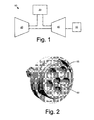
- Fig. 1 shows a schematic view of a gas turbine engine 10.
- the gas turbine engine 10 may include a compressor 20 to compress an incoming flow of air.
- the compressor 20 delivers the compressed flow of air to a combustor 30.
- the combustor 30 mixes the compressed flow of air with a compressed flow of fuel and ignites the mixture.
- the gas turbine engine 10 may include any number of combustors 30.
- the hot combustion gases are in turn delivered to a turbine 40.
- the hot combustion gases drive the turbine 40 so as to produce mechanical work.
- Mechanical work produced by the turbine 40 drives the compressor 20 and an external load 50 such as an electrical generator and the like.
- the gas turbine engine 10 may use natural gas, various types of syngas, and other types of fuels.
- the gas turbine engine 10 may have other configurations and may use other types of components herein.
- Figs. 2 through 4 show an existing fuel nozzle 60.
- a 9FBA center fuel nozzle 60 is shown.
- the fuel nozzle 60 is positioned within a cap assembly 65.
- the cap assembly 65 may be part of the DLN2.6+ combustion system.
- the DLN2.6+ combustion system uses a five around one nozzle configuration.
- the nozzle 60 is held within the cap assembly 65 via a floating collar 70 riding along a machined ring 75 on the fuel nozzle 60.
- the 9FBA center fuel nozzle 60 operates at about zero margin to 3/rev rotor speed. As described above, high amplitude resonance has resulted in issues between a flange 80 and an outer premixer tube 85 of the fuel nozzle 60.
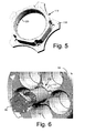
- Figs. 5 through 7 show a fuel nozzle spring system 100 as is described herein.
- the fuel nozzle spring support system 100 includes a spring support 110 positioned between the fuel nozzle 60 and the cap assembly 65.
- the spring support 110 includes a hula seal 120 positioned within an outer collar 130.
- the hula seal 120 is defined as a system of leaf springs formed into a round loop.
- the hula seal 120 generally is used to seal a sliding interface joint or annular cap between two concentric ducts.
- the hula seal 120 provides spring stiffness and dampening to the fuel nozzle spring system 100. As is shown in Figs. 6 and 7 , the hula seal 120 may be positioned against the machined ring 70 of the fuel nozzle 60 instead of the use of the floating collar 70. The hula seal 120 supports the fuel nozzle 60 at a full 360 degrees around.
- the spring support 110 may use a number of hula seals 120 therein. In addition to providing stiffness, frictional losses in the hula seal 120 may provide mechanical damping to reduce vibration amplitudes.
- the use of the hula seal 120 at the mid-span of the fuel nozzle 60 thus may increase the natural frequency of the nozzle 60.
- the hula seal 120 may raise the first natural frequency of the nozzle 60 from about 150 Hz to above about 230 Hz. Based upon the available space, the hula seal 120 may increase the natural frequency by about four times or more.
- the hula seal 120 and the stiffness of the seal may be sized to move the natural frequency of the fuel nozzle to a desired range.
- the hula seal 120 preferably has a stiffness of about 70 klb/in and may range from about 30 klb/in to over about 150 klb/in.
- the hula seal 120 may be made out of Inconel X750 (a Nickel-Chromium alloy made precipitation hardenable by additions of Aluminum and Titanium, having creep-rupture strength at high temperatures to about 700°C (1290°F)) or similar types of materials.
- the use of the spring support 110 thus avoids costly retrofitting of the center fuel nozzle 60 and the cap assembly 65. Moreover, the use of the spring support 110 may be retrofitted on site. The spring support 110 likewise may increase the useful lifetime of the fuel nozzle 60.
Landscapes
- Engineering & Computer Science (AREA)
- Chemical & Material Sciences (AREA)
- Combustion & Propulsion (AREA)
- Mechanical Engineering (AREA)
- General Engineering & Computer Science (AREA)
- Turbine Rotor Nozzle Sealing (AREA)
- Closures For Containers (AREA)
Abstract
Description
- The present application relates generally to gas turbine engines and more particularly relates to a spring support used to position a fuel nozzle within a cap assembly of a turbine combustor.
- Gas turbine engines generally include a combustor with a number of fuel nozzles positioned therein in various configurations. For example, a DLN2.6+ ("Dry Low NOx") combustion system offered by General Electric Corporation of Schenectady, New York provides a six fuel nozzle configuration with a center fuel nozzle surrounded by five outer fuel nozzles. Such a combustion system mixes one or more fuel streams and air streams before entry into a reaction or a combustion zone. Such premixing tends to reduce overall combustion temperatures as well as undesirable emissions such as nitrogen oxides (NOx).
- As is known, the fuel nozzles generally include a number of fuel and air tubes mounted onto a flange. In the DLN2.6+ combustion system, the fuel nozzles may be positioned within a cap assembly in a somewhat cantilevered fashion. The combination of the cantilevered structure and the natural frequency of the center fuel nozzles, however, have caused somewhat high amplitude resonance that has resulted in issues with respect to a braised joint between the flange and one of the outer premixed tubes.
- Although the design of the fuel nozzle and the cap assembly may be revised to eliminate the issue with the joint, there is a considerable amount of equipment currently operating in the field. There is a desire therefore for systems and methods to dampen or at least to shift the natural frequency of the center fuel tube so as to avoid any issues that may arise with high amplitude resonance. The systems and methods preferably can dampen or shift the natural frequency of the fuel nozzle without extensive equipment replacement or modification costs.
- The present application thus provides a fuel nozzle spring support system. The fuel nozzle spring support system may include a fuel nozzle, a cap assembly, and a spring support positioned between the fuel nozzle and the cap assembly.
- The present application further provides a method of operating a combustor having a fuel nozzle and a cap assembly. The method may include the steps of sizing a spring support to alter the natural frequency of the fuel nozzle, positioning the spring support between the fuel nozzle and the cap assembly, and operating the fuel nozzle at the altered natural frequency.
- The present application further provides a fuel nozzle spring support system. The fuel nozzle spring support system may include a fuel nozzle, a cap assembly, and a spring support positioned between the fuel nozzle and the cap assembly. The spring support may include a hula seal and a collar.
- These and other features of the present application will become apparent to one of ordinary skill in the art upon review of the following detailed description when taken in conjunction with the several drawings and the appended claims.
- There follows a detailed description of embodiments of the invention by way of example only with reference to the accompanying drawings, in which:
-
Fig. 1 is a schematic view of a gas turbine engine; -
Fig. 2 is a perspective view of a known fuel nozzle and cap assembly; -
Fig. 3 is a side cross-sectional view of the fuel nozzle and cap assembly ofFig. 2 ; -
Fig. 4 is a side cross-sectional view of a machined ring of the fuel nozzle and a floating collar of the cap assembly of theFig. 2 ; -
Fig. 5 is a perspective view of a fuel nozzle spring support as is described herein; -
Fig. 6 is a perspective view of a fuel nozzle spring support system as is described herein with a fuel nozzle and a cap assembly; and -
Fig. 7 is a side cross-sectional view of a machined ring of the fuel nozzle, the spring support, and the cap assembly of theFig. 6 . - Referring now to the drawings, in which like numbers refer to like elements throughout the several views,
Fig. 1 shows a schematic view of agas turbine engine 10. As is known, thegas turbine engine 10 may include acompressor 20 to compress an incoming flow of air. Thecompressor 20 delivers the compressed flow of air to acombustor 30. Thecombustor 30 mixes the compressed flow of air with a compressed flow of fuel and ignites the mixture. (Although asingle combustor 30 is shown, thegas turbine engine 10 may include any number ofcombustors 30.) The hot combustion gases are in turn delivered to aturbine 40. The hot combustion gases drive theturbine 40 so as to produce mechanical work. Mechanical work produced by theturbine 40 drives thecompressor 20 and anexternal load 50 such as an electrical generator and the like. Thegas turbine engine 10 may use natural gas, various types of syngas, and other types of fuels. Thegas turbine engine 10 may have other configurations and may use other types of components herein. -
Figs. 2 through 4 show an existingfuel nozzle 60. Specifically, a 9FBAcenter fuel nozzle 60 is shown. Thefuel nozzle 60 is positioned within acap assembly 65. Thecap assembly 65 may be part of the DLN2.6+ combustion system. As is shown, the DLN2.6+ combustion system uses a five around one nozzle configuration. Specifically, thenozzle 60 is held within thecap assembly 65 via afloating collar 70 riding along a machinedring 75 on thefuel nozzle 60. The 9FBAcenter fuel nozzle 60 operates at about zero margin to 3/rev rotor speed. As described above, high amplitude resonance has resulted in issues between aflange 80 and anouter premixer tube 85 of thefuel nozzle 60. -
Figs. 5 through 7 show a fuelnozzle spring system 100 as is described herein. The fuel nozzlespring support system 100 includes aspring support 110 positioned between thefuel nozzle 60 and thecap assembly 65. As is shown inFig. 5 , thespring support 110 includes ahula seal 120 positioned within anouter collar 130. As described in, for example, commonly ownedU.S. Patent No. 6,334,310 , thehula seal 120 is defined as a system of leaf springs formed into a round loop. Thehula seal 120 generally is used to seal a sliding interface joint or annular cap between two concentric ducts. - The
hula seal 120 provides spring stiffness and dampening to the fuelnozzle spring system 100. As is shown inFigs. 6 and7 , thehula seal 120 may be positioned against themachined ring 70 of thefuel nozzle 60 instead of the use of thefloating collar 70. Thehula seal 120 supports thefuel nozzle 60 at a full 360 degrees around. Thespring support 110 may use a number ofhula seals 120 therein. In addition to providing stiffness, frictional losses in thehula seal 120 may provide mechanical damping to reduce vibration amplitudes. - The use of the
hula seal 120 at the mid-span of thefuel nozzle 60 thus may increase the natural frequency of thenozzle 60. Specifically, thehula seal 120 may raise the first natural frequency of thenozzle 60 from about 150 Hz to above about 230 Hz. Based upon the available space, thehula seal 120 may increase the natural frequency by about four times or more. Thehula seal 120 and the stiffness of the seal may be sized to move the natural frequency of the fuel nozzle to a desired range. Thehula seal 120 preferably has a stiffness of about 70 klb/in and may range from about 30 klb/in to over about 150 klb/in. Thehula seal 120 may be made out of Inconel X750 (a Nickel-Chromium alloy made precipitation hardenable by additions of Aluminum and Titanium, having creep-rupture strength at high temperatures to about 700°C (1290°F)) or similar types of materials. - The use of the
spring support 110 thus avoids costly retrofitting of thecenter fuel nozzle 60 and thecap assembly 65. Moreover, the use of thespring support 110 may be retrofitted on site. Thespring support 110 likewise may increase the useful lifetime of thefuel nozzle 60. - It should be apparent that the foregoing relates only to certain embodiments of the present application and that numerous changes and modifications may be made herein by one of ordinary skill in the art without departing from the general spirit and scope of the invention as defmed by the following claims and the equivalents thereof.
Claims (15)
- A fuel nozzle spring support system (100), comprising:a fuel nozzle (60);a cap assembly (65); anda spring support (110) positioned between the fuel nozzle (60) and the cap assembly (65).
- The fuel nozzle spring support system (100) of claim 1, wherein the spring support (110) comprises a hula seal (120).
- The fuel nozzle spring support system (100) of claim 2, wherein the spring support (110) comprises a collar (130) surrounding the hula seal (120).
- The fuel nozzle spring support system (100) of claim 2 or 3, wherein the hula seal (120) surrounds the fuel nozzle (60).
- The fuel nozzle spring support system (100) of any of claims 2 to 4, wherein the hula seal (120) comprises a stiffness of about 30 to over 150 klb/in.
- The fuel nozzle spring support system (100) of any of claims 2 to 5, wherein the hula seal (120) comprises a Nickel-Chromium alloy.
- The fuel nozzle spring support system (100) of any of claims 2 to 6, wherein the hula seal (120) comprises a plurality of hula seals (120).
- The fuel nozzle spring support system (100) of any of the preceding claims, wherein the fuel nozzle (60) comprises a ring (75) thereabout and wherein the spring support (110) is positioned about the ring (75).
- The fuel nozzle spring support system (100 of any of the preceding claims, wherein the natural frequency of the fuel nozzle (60) comprises greater than about 230 Hz when the spring seal (110) is positioned thereon.
- A method of operating combustor (30) having a fuel nozzle (60) and a cap assembly (65), comprising:sizing a spring support (110) to alter the natural frequency of the fuel nozzle (60);positioning the spring support (110) between the fuel nozzle (60) and the cap assembly (65); andoperating the fuel nozzle (60) at the altered natural frequency.
- A fuel nozzle spring support system, comprising:a fuel nozzle;a cap assembly; anda spring support positioned between the fuel nozzle and the cap assembly;wherein the spring support comprises a hula seal and a collar.
- The fuel nozzle spring support system of claim 11, wherein the hula seal surrounds the fuel nozzle.
- The fuel nozzle spring support system of claim 11 or 12, wherein the hula seal comprises a stiffness of about 30 to over 150 klb/in.
- The fuel nozzle spring support system of any of claims 11 to 13, wherein the hula seal comprises a Nickel-Chromium alloy.
- The fuel nozzle spring support system of any of claims 11 to 14, wherein the hula seal comprises a plurality of hula seals.
Applications Claiming Priority (1)
| Application Number | Priority Date | Filing Date | Title |
|---|---|---|---|
| US12/413,639 US8528336B2 (en) | 2009-03-30 | 2009-03-30 | Fuel nozzle spring support for shifting a natural frequency |
Publications (2)
| Publication Number | Publication Date |
|---|---|
| EP2239507A2 true EP2239507A2 (en) | 2010-10-13 |
| EP2239507A3 EP2239507A3 (en) | 2014-08-13 |
Family
ID=42269991
Family Applications (1)
| Application Number | Title | Priority Date | Filing Date |
|---|---|---|---|
| EP10157407.7A Withdrawn EP2239507A3 (en) | 2009-03-30 | 2010-03-23 | Fuel nozzle spring support |
Country Status (4)
| Country | Link |
|---|---|
| US (1) | US8528336B2 (en) |
| EP (1) | EP2239507A3 (en) |
| JP (1) | JP2010236547A (en) |
| CN (1) | CN101858598A (en) |
Cited By (1)
| Publication number | Priority date | Publication date | Assignee | Title |
|---|---|---|---|---|
| DE102011003798A1 (en) * | 2011-02-08 | 2012-08-09 | Siemens Aktiengesellschaft | Burner carrier with separate inner and outer flange |
Families Citing this family (34)
| Publication number | Priority date | Publication date | Assignee | Title |
|---|---|---|---|---|
| US8938976B2 (en) * | 2011-05-20 | 2015-01-27 | Siemens Energy, Inc. | Structural frame for gas turbine combustion cap assembly |
| US9103551B2 (en) * | 2011-08-01 | 2015-08-11 | General Electric Company | Combustor leaf seal arrangement |
| US9404655B2 (en) * | 2012-01-20 | 2016-08-02 | General Electric Company | Process of fabricating a fuel nozzle assembly |
| US9163839B2 (en) * | 2012-03-19 | 2015-10-20 | General Electric Company | Micromixer combustion head end assembly |
| US20130327011A1 (en) * | 2012-06-08 | 2013-12-12 | Brandon Taylor Overby | Method And Apparatus For A Fuel Nozzle Assembly For Use With A Combustor |
| US20130333389A1 (en) * | 2012-06-15 | 2013-12-19 | General Electric Company | Cross fire tube retention system for a gas turbine engine |
| US9003803B2 (en) * | 2012-08-03 | 2015-04-14 | General Electric Company | Combustor cap assembly |
| US20140060077A1 (en) * | 2012-08-31 | 2014-03-06 | General Electric Company | Combustor |
| US9046038B2 (en) * | 2012-08-31 | 2015-06-02 | General Electric Company | Combustor |
| US9297533B2 (en) | 2012-10-30 | 2016-03-29 | General Electric Company | Combustor and a method for cooling the combustor |
| US8756934B2 (en) | 2012-10-30 | 2014-06-24 | General Electric Company | Combustor cap assembly |
| US9151503B2 (en) * | 2013-01-04 | 2015-10-06 | General Electric Company | Coaxial fuel supply for a micromixer |
| US9765973B2 (en) | 2013-03-12 | 2017-09-19 | General Electric Company | System and method for tube level air flow conditioning |
| US9651259B2 (en) | 2013-03-12 | 2017-05-16 | General Electric Company | Multi-injector micromixing system |
| US9347668B2 (en) | 2013-03-12 | 2016-05-24 | General Electric Company | End cover configuration and assembly |
| US9759425B2 (en) | 2013-03-12 | 2017-09-12 | General Electric Company | System and method having multi-tube fuel nozzle with multiple fuel injectors |
| US9650959B2 (en) | 2013-03-12 | 2017-05-16 | General Electric Company | Fuel-air mixing system with mixing chambers of various lengths for gas turbine system |
| US9534787B2 (en) * | 2013-03-12 | 2017-01-03 | General Electric Company | Micromixing cap assembly |
| US9366439B2 (en) | 2013-03-12 | 2016-06-14 | General Electric Company | Combustor end cover with fuel plenums |
| US9528444B2 (en) | 2013-03-12 | 2016-12-27 | General Electric Company | System having multi-tube fuel nozzle with floating arrangement of mixing tubes |
| US9671112B2 (en) | 2013-03-12 | 2017-06-06 | General Electric Company | Air diffuser for a head end of a combustor |
| DE102013007443A1 (en) | 2013-04-30 | 2014-10-30 | Rolls-Royce Deutschland Ltd & Co Kg | Burner seal for gas turbine combustor head and heat shield |
| CN104566478B (en) * | 2014-12-26 | 2017-09-15 | 北京华清燃气轮机与煤气化联合循环工程技术有限公司 | It is a kind of to strengthen the supporting construction of gas-turbine combustion chamber cap stability |
| KR101657536B1 (en) * | 2015-04-27 | 2016-09-19 | 두산중공업 주식회사 | Nozzle assembly comprising spring for vibration reduction |
| KR101857280B1 (en) | 2015-06-30 | 2018-05-11 | 두산중공업 주식회사 | Gas turbine provided with a device for improved fuel flow distribution. |
| KR101873573B1 (en) * | 2015-09-04 | 2018-07-03 | 두산중공업 주식회사 | Nozzle assembly comprising spring for vibration reduction |
| JP6617004B2 (en) * | 2015-11-04 | 2019-12-04 | 三菱日立パワーシステムズ株式会社 | Seal member and method for manufacturing seal member |
| JP6621303B2 (en) * | 2015-11-04 | 2019-12-18 | 三菱日立パワーシステムズ株式会社 | Seal member and method for manufacturing seal member |
| US10429073B2 (en) * | 2015-12-21 | 2019-10-01 | General Electric Company | Combustor cap module and retention system therefor |
| US10677465B2 (en) * | 2017-05-16 | 2020-06-09 | General Electric Company | Combustor mounting assembly having a spring finger for forming a seal with a fuel injector assembly |
| KR102019091B1 (en) * | 2017-10-31 | 2019-11-04 | 두산중공업 주식회사 | Fuel nozzle assembly, combustor and gas turbine having the same |
| KR102142094B1 (en) * | 2019-03-05 | 2020-08-06 | 두산중공업 주식회사 | Fuel nozzle assembly and combustor and gas turbine having the same |
| CN116677470B (en) * | 2022-02-23 | 2026-01-16 | 中国航发商用航空发动机有限责任公司 | Multi-point miniature friction damping vibration damper for fuel nozzle |
| US12460821B2 (en) * | 2023-02-15 | 2025-11-04 | Solar Turbines Incorporated | Fuel injector panels having micromixers |
Citations (1)
| Publication number | Priority date | Publication date | Assignee | Title |
|---|---|---|---|---|
| US6334310B1 (en) | 2000-06-02 | 2002-01-01 | General Electric Company | Fracture resistant support structure for a hula seal in a turbine combustor and related method |
Family Cites Families (15)
| Publication number | Priority date | Publication date | Assignee | Title |
|---|---|---|---|---|
| US4151713A (en) * | 1977-03-15 | 1979-05-01 | United Technologies Corporation | Burner for gas turbine engine |
| US4285633A (en) * | 1979-10-26 | 1981-08-25 | The United States Of America As Represented By The Secretary Of The Air Force | Broad spectrum vibration damper assembly fixed stator vanes of axial flow compressor |
| US5274991A (en) * | 1992-03-30 | 1994-01-04 | General Electric Company | Dry low NOx multi-nozzle combustion liner cap assembly |
| EP0564181B1 (en) * | 1992-03-30 | 1996-11-20 | General Electric Company | Combustor dome construction |
| US6547256B2 (en) * | 2000-12-26 | 2003-04-15 | General Electric Company | Cloth ring seal |
| JP4709433B2 (en) * | 2001-06-29 | 2011-06-22 | 三菱重工業株式会社 | Gas turbine combustor |
| US6880341B2 (en) * | 2002-12-18 | 2005-04-19 | Pratt & Whitney Canada Corp. | Low cost combustor floating collar with improved sealing and damping |
| US7140189B2 (en) * | 2004-08-24 | 2006-11-28 | Pratt & Whitney Canada Corp. | Gas turbine floating collar |
| US7082766B1 (en) * | 2005-03-02 | 2006-08-01 | General Electric Company | One-piece can combustor |
| US20060230763A1 (en) * | 2005-04-13 | 2006-10-19 | General Electric Company | Combustor and cap assemblies for combustors in a gas turbine |
| US8141370B2 (en) * | 2006-08-08 | 2012-03-27 | General Electric Company | Methods and apparatus for radially compliant component mounting |
| US7827797B2 (en) * | 2006-09-05 | 2010-11-09 | General Electric Company | Injection assembly for a combustor |
| US8438853B2 (en) * | 2008-01-29 | 2013-05-14 | Alstom Technology Ltd. | Combustor end cap assembly |
| US8549859B2 (en) * | 2008-07-28 | 2013-10-08 | Siemens Energy, Inc. | Combustor apparatus in a gas turbine engine |
| US8429919B2 (en) * | 2009-05-28 | 2013-04-30 | General Electric Company | Expansion hula seals |
-
2009
- 2009-03-30 US US12/413,639 patent/US8528336B2/en not_active Expired - Fee Related
-
2010
- 2010-03-23 EP EP10157407.7A patent/EP2239507A3/en not_active Withdrawn
- 2010-03-24 JP JP2010067175A patent/JP2010236547A/en active Pending
- 2010-03-30 CN CN201010156384A patent/CN101858598A/en active Pending
Patent Citations (1)
| Publication number | Priority date | Publication date | Assignee | Title |
|---|---|---|---|---|
| US6334310B1 (en) | 2000-06-02 | 2002-01-01 | General Electric Company | Fracture resistant support structure for a hula seal in a turbine combustor and related method |
Cited By (2)
| Publication number | Priority date | Publication date | Assignee | Title |
|---|---|---|---|---|
| DE102011003798A1 (en) * | 2011-02-08 | 2012-08-09 | Siemens Aktiengesellschaft | Burner carrier with separate inner and outer flange |
| WO2012107257A3 (en) * | 2011-02-08 | 2013-07-04 | Siemens Aktiengesellschaft | Burner carrier having separate inner flange and outer flange |
Also Published As
| Publication number | Publication date |
|---|---|
| CN101858598A (en) | 2010-10-13 |
| EP2239507A3 (en) | 2014-08-13 |
| US20100242493A1 (en) | 2010-09-30 |
| JP2010236547A (en) | 2010-10-21 |
| US8528336B2 (en) | 2013-09-10 |
Similar Documents
| Publication | Publication Date | Title |
|---|---|---|
| US8528336B2 (en) | Fuel nozzle spring support for shifting a natural frequency | |
| US10816078B2 (en) | Systems and methods for a gas turbine engine with combined multi-directional gearbox deflection limiters and dampers | |
| US9033699B2 (en) | Combustor | |
| US9353950B2 (en) | System for reducing combustion dynamics and NOx in a combustor | |
| US9528444B2 (en) | System having multi-tube fuel nozzle with floating arrangement of mixing tubes | |
| US8429919B2 (en) | Expansion hula seals | |
| EP2208933B1 (en) | Combustor assembly and cap for a turbine engine | |
| US8511086B1 (en) | System and method for reducing combustion dynamics in a combustor | |
| EP3220047B1 (en) | Gas turbine flow sleeve mounting | |
| EP2636952A2 (en) | A fuel nozzle and a combustor for a gas turbine | |
| EP2634488A1 (en) | System and method for reducing combustion dynamics in a combustor | |
| US8733108B2 (en) | Combustor and combustor screech mitigation methods | |
| EP3312510A1 (en) | Combustor assembly with air shield for a radial fuel injector | |
| US9249734B2 (en) | Combustor | |
| EP3220053A1 (en) | Axially staged fuel injector assembly and method of mounting | |
| US20110162375A1 (en) | Secondary Combustion Fuel Supply Systems | |
| US9303871B2 (en) | Combustor assembly including a transition inlet cone in a gas turbine engine | |
| EP2592345A1 (en) | Combustor and method for supplying fuel to a combustor | |
| EP2672184A2 (en) | Method and apparatus for a fuel nozzle assembly for use with a combustor | |
| US8413447B2 (en) | Fuel nozzle cup seal | |
| US9528703B2 (en) | Micro-mixer fuel plenum and methods for fuel tube installation | |
| EP2525153A1 (en) | Flexible combustor fuel nozzle | |
| US20180245792A1 (en) | Combustion System with Axially Staged Fuel Injection | |
| WO2016027769A1 (en) | Fuel injection device |
Legal Events
| Date | Code | Title | Description |
|---|---|---|---|
| PUAI | Public reference made under article 153(3) epc to a published international application that has entered the european phase |
Free format text: ORIGINAL CODE: 0009012 |
|
| AK | Designated contracting states |
Kind code of ref document: A2 Designated state(s): AT BE BG CH CY CZ DE DK EE ES FI FR GB GR HR HU IE IS IT LI LT LU LV MC MK MT NL NO PL PT RO SE SI SK SM TR |
|
| PUAL | Search report despatched |
Free format text: ORIGINAL CODE: 0009013 |
|
| AK | Designated contracting states |
Kind code of ref document: A3 Designated state(s): AT BE BG CH CY CZ DE DK EE ES FI FR GB GR HR HU IE IS IT LI LT LU LV MC MK MT NL NO PL PT RO SE SI SK SM TR |
|
| RIC1 | Information provided on ipc code assigned before grant |
Ipc: F23R 3/28 20060101AFI20140710BHEP |
|
| 17P | Request for examination filed |
Effective date: 20140813 |
|
| RBV | Designated contracting states (corrected) |
Designated state(s): AT BE BG CH CY CZ DE DK EE ES FI FR GB GR HR HU IE IS IT LI LT LU LV MC MK MT NL NO PL PT RO SE SI SK SM TR |
|
| GRAP | Despatch of communication of intention to grant a patent |
Free format text: ORIGINAL CODE: EPIDOSNIGR1 |
|
| INTG | Intention to grant announced |
Effective date: 20141223 |
|
| STAA | Information on the status of an ep patent application or granted ep patent |
Free format text: STATUS: THE APPLICATION IS DEEMED TO BE WITHDRAWN |
|
| 18D | Application deemed to be withdrawn |
Effective date: 20150505 |