EP2239227A1 - Carbon nanotube synthesizer - Google Patents
Carbon nanotube synthesizer Download PDFInfo
- Publication number
- EP2239227A1 EP2239227A1 EP08871754A EP08871754A EP2239227A1 EP 2239227 A1 EP2239227 A1 EP 2239227A1 EP 08871754 A EP08871754 A EP 08871754A EP 08871754 A EP08871754 A EP 08871754A EP 2239227 A1 EP2239227 A1 EP 2239227A1
- Authority
- EP
- European Patent Office
- Prior art keywords
- internal heating
- reactor pipe
- nozzles
- distance
- nozzle
- Prior art date
- Legal status (The legal status is an assumption and is not a legal conclusion. Google has not performed a legal analysis and makes no representation as to the accuracy of the status listed.)
- Granted
Links
Images


Classifications
-
- B—PERFORMING OPERATIONS; TRANSPORTING
- B82—NANOTECHNOLOGY
- B82B—NANOSTRUCTURES FORMED BY MANIPULATION OF INDIVIDUAL ATOMS, MOLECULES, OR LIMITED COLLECTIONS OF ATOMS OR MOLECULES AS DISCRETE UNITS; MANUFACTURE OR TREATMENT THEREOF
- B82B3/00—Manufacture or treatment of nanostructures by manipulation of individual atoms or molecules, or limited collections of atoms or molecules as discrete units
- B82B3/0004—Apparatus specially adapted for the manufacture or treatment of nanostructural devices or systems or methods for manufacturing the same
-
- C—CHEMISTRY; METALLURGY
- C01—INORGANIC CHEMISTRY
- C01B—NON-METALLIC ELEMENTS; COMPOUNDS THEREOF; METALLOIDS OR COMPOUNDS THEREOF NOT COVERED BY SUBCLASS C01C
- C01B32/00—Carbon; Compounds thereof
- C01B32/15—Nano-sized carbon materials
- C01B32/158—Carbon nanotubes
- C01B32/16—Preparation
-
- B—PERFORMING OPERATIONS; TRANSPORTING
- B01—PHYSICAL OR CHEMICAL PROCESSES OR APPARATUS IN GENERAL
- B01J—CHEMICAL OR PHYSICAL PROCESSES, e.g. CATALYSIS OR COLLOID CHEMISTRY; THEIR RELEVANT APPARATUS
- B01J19/00—Chemical, physical or physico-chemical processes in general; Their relevant apparatus
- B01J19/24—Stationary reactors without moving elements inside
-
- B—PERFORMING OPERATIONS; TRANSPORTING
- B01—PHYSICAL OR CHEMICAL PROCESSES OR APPARATUS IN GENERAL
- B01J—CHEMICAL OR PHYSICAL PROCESSES, e.g. CATALYSIS OR COLLOID CHEMISTRY; THEIR RELEVANT APPARATUS
- B01J4/00—Feed or outlet devices; Feed or outlet control devices
- B01J4/001—Feed or outlet devices as such, e.g. feeding tubes
- B01J4/002—Nozzle-type elements
-
- B—PERFORMING OPERATIONS; TRANSPORTING
- B82—NANOTECHNOLOGY
- B82B—NANOSTRUCTURES FORMED BY MANIPULATION OF INDIVIDUAL ATOMS, MOLECULES, OR LIMITED COLLECTIONS OF ATOMS OR MOLECULES AS DISCRETE UNITS; MANUFACTURE OR TREATMENT THEREOF
- B82B3/00—Manufacture or treatment of nanostructures by manipulation of individual atoms or molecules, or limited collections of atoms or molecules as discrete units
- B82B3/0009—Forming specific nanostructures
-
- B—PERFORMING OPERATIONS; TRANSPORTING
- B82—NANOTECHNOLOGY
- B82Y—SPECIFIC USES OR APPLICATIONS OF NANOSTRUCTURES; MEASUREMENT OR ANALYSIS OF NANOSTRUCTURES; MANUFACTURE OR TREATMENT OF NANOSTRUCTURES
- B82Y30/00—Nanotechnology for materials or surface science, e.g. nanocomposites
-
- B—PERFORMING OPERATIONS; TRANSPORTING
- B82—NANOTECHNOLOGY
- B82Y—SPECIFIC USES OR APPLICATIONS OF NANOSTRUCTURES; MEASUREMENT OR ANALYSIS OF NANOSTRUCTURES; MANUFACTURE OR TREATMENT OF NANOSTRUCTURES
- B82Y40/00—Manufacture or treatment of nanostructures
-
- B—PERFORMING OPERATIONS; TRANSPORTING
- B01—PHYSICAL OR CHEMICAL PROCESSES OR APPARATUS IN GENERAL
- B01J—CHEMICAL OR PHYSICAL PROCESSES, e.g. CATALYSIS OR COLLOID CHEMISTRY; THEIR RELEVANT APPARATUS
- B01J2219/00—Chemical, physical or physico-chemical processes in general; Their relevant apparatus
- B01J2219/00049—Controlling or regulating processes
- B01J2219/00051—Controlling the temperature
- B01J2219/00132—Controlling the temperature using electric heating or cooling elements
- B01J2219/00135—Electric resistance heaters
Definitions
- the present invention relates to a structure of a device for carbon nanotubes synthesis.
- a vapor-phase flow method As a method for synthesizing carbon nanotubes, a vapor-phase flow method is known. In this method, a material containing a carbon source, a catalyst and the like is supplied into a heated cylindrical reactor pipe, and carbon nanotubes are made to grow in a state floating in the reactor pipe.
- the carbon nanotube has attracted attention recently as a new material having new possibilities, and industrial uses thereof have been examined. For industrial use, increase of a production amount is in demand.
- Patent Document 1 discloses a technique for increasing a yield by enlarging a diameter of a lab level reactor pipe and by increasing the number of material injection nozzles. In that case, in order to eliminate unevenness in temperature inside the reactor pipe, an internal heating source is arranged inside the reactor pipe.
- Patent Document 1 Japanese Patent Laid-Open Publication No. 2005-41752
- a carbon nanotube synthesizer of the present invention includes a cylindrical reactor pipe heated by a heating device so as to be a cylindrical heating element, a tubular or columnar internal heating source arranged inside the reactor pipe so as to have an axis parallel with the axis of the reactor pipe, and a plurality of material injection nozzles for supplying a material and a carrier gas into the reactor pipe along a direction parallel with the axis of the reactor pipe.
- the carrier gas is supplied so as to surround the periphery of the injected material.
- the nozzles are arranged so that a distance between one of the nozzles and two heating bodies (the circumference heating element or the internal heating source) closest to this nozzle is a first distance, and a distance from this nozzle to a nozzle closest to this nozzle is a second distance, which is twice or more of the first distance.
- a yield of the carbon nanotube synthesizer can be improved.
- 10 carbon nanotube producing device 16 synthesizer, 20 reactor pipe (circumference heating element), 24, 34, 44, 54a, 54b, 64a, 64b internal heating source, 26, 36, 46, 56a, 56b, 66a, 66b material injection nozzle.
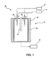
- FIG. 1 is an outline configuration diagram of a carbon nanotube producing device 10.
- the carbon nanotube producing device 10 includes a material supplying device 12 for supplying a material, a carrier gas supplying device 14 for supplying a carrier gas, a synthesizer 16 for synthesizing carbon nanotubes from the material, and a collecting device 18 for collecting the synthesized carbon nanotubes.
- the material includes a carbon source, a catalyst, and auxiliaries.
- the carrier gas does not directly relate to synthesis of the carbon nanotubes but is used for adjusting a material reaction condition inside the synthesizer 16.
- the synthesizer 16 includes a substantially cylindrical reactor pipe 20 and a heating device 22 arranged so as to surround the reactor pipe 20.
- the reactor pipe 20 is arranged so that its cylindrical axis is along the vertical direction, that is, a direction in which gravity acts.
- gravity includes pseudo gravity caused by an inertial force such as a centrifugal force in addition to the intermoleculer force.
- the reactor pipe 20 is heated by the heating device 22 so as to have a high temperature and to become a circumference heating element heating the inside wall of the pipe.
- an internal heating source 24 is further arranged.
- the internal heating source 24 has a tubular, columnar, or preferably circular tubular or circular cylinder shape, and is arranged so that its axis is parallel to the cylindrical axis of the reactor pipe 20. In this embodiment, a circular cylinder shape is employed. The concept of "parallelism" in this case also includes a coaxial arrangement of the reactor pipe 20 and the internal heating source 24.
- the internal heating source is arranged in single or in plural, and the arrangement will be described later.
- a heating element using an electric resistunce can be used as the heating device 22 and the internal heating source 24.
- a plurality of nozzles 26 for supplying the material and the carrier gas are arranged.
- the material has a transition metal compound to be a catalyst and a reaction auxiliary added to a solvent containing a carbon source with prior adjustment, and is supplied by the material supplying device 12 to the nozzles 26 through a pump.
- the material is injected into the reactor pipe 20 as fine droplet particles from a distal end of the nozzle 26.
- the carrier gas is supplied by the carrier gas supplying device 14 into the reactor pipe 20 from the vicinity of the nozzles 26 while an appropriate flow rate is controlled by a mass flow meter.
- a distal end portion of the nozzle 26 is configured to supply the material and the carrier gas separately into the reactor pipe.
- the material is injected from the center of the distal end of the nozzle 26, while the carrier gas is supplied from the peripheral part of the distal end, and a resulting ring-shaped flow with a sectional shape surrounding the material droplet flows through the reactor pipe.
- the material droplets receive heat from the circumference heating element and the internal heating source while flowing down through the reactor pipe 20, and carbon nanotubes are synthesized by actions of carbon generated by thermal decomposition of the carbon source, metal particles generated by thermal decomposition of the transition metal compound, and the auxiliary.
- a discharged gas containing the synthesized carbon nanotubes is discharged and fed to the collecting device 18.
- the carbon nanotubes are separated from the discharged gas and collected.
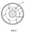
- FIG. 2 is a transverse cross section of the synthesizer 16 in FIG. 1 .
- An example of a single unit of the internal heating source 24 and 6 units of the nozzles 26 is shown.
- the internal heating source 24 is arranged coaxially with the reactor pipe 20, which is a circumference heating element.
- the nozzles 26 are arranged on a circle 28 at an equal distance a from an inner wall of the reactor pipe 20 and a peripheral surface of the internal heating source 24.
- the nozzles 26 are arranged so that a distance between the adjacent nozzles is a distance b, which is approximately twice the distance a.
- the distance a is a distance between the nozzle and the reactor pipe inner wall surface acquired from the synthesizer in which a single nozzle is disposed at the center of a reactor pipe so that synthesis of high yield and high quality carbon nanotubes is to be realized.
- the arrangement of the internal heating source and the nozzle is considered so that at least two heating bodies (the reactor pipe and the internal heating source) at this distance a are provided for one nozzle, or more preferably, the arrangement in which the nozzle is sandwiched by two heating sources is considered.
- the distance a is considered to be a distance with which flows of the material and the carrier gas supplied from the adjacent nozzles 26 do not interfere with the reactor pipe inner wall.
- the distance b is preferably twice or more the distance a.
- the distance b is preferably set at twice the distance a. In order to achieve the distance b of twice the distance a, a diameter of the internal heating source 24 is adjusted.
- FIG. 3 is a diagram illustrating another arrangement example of the internal heating sources and nozzles.
- a circle formed by the inner wall of the reactor pipe 20 is divided into three sectors.
- the center of the internal heating source 34 is arranged.
- a distance between the circle 32 and the internal heating source 34 is made a, and the circle 32 passes through a midpoint between the peripheral wall of the internal heating source 34 and the inner wall of the reactor pipe 20.
- the nozzles 36 are arranged at contacts between the circles 32, and a diameter of the internal heating source 34 is determined so that the distance b between the nozzles is twice or more the distance a, and the shortest distance between the peripheral wall of the internal heating source 34 and the internal wall of the reactor pipe 20 is 2a.
- the arrangement in FIG. 3 is as follows.
- the three internal heating sources 34 are arranged on a single circumference concentric to the reactor pipe 20. For one internal heating source 34, one nozzle 36 is arranged between that and the reactor pipe 20, and one nozzle each corresponds to each of the three internal heating source. Also, between the adjacent internal heating sources 34, one nozzle 36 is arranged, and the three nozzles in total are arranged.
- FIG. 4 is a diagram illustrating still another arrangement example of the internal heating sources and the nozzles. There are arranged four units of internal heating sources 44 and eight units of the nozzles 46.
- the arranging method is basically the same as in FIG. 3 .
- the circle formed by the inner wall of the reactor pipe 20 is equally divided into three parts, but in the example in FIG. 4 , it is equally divided into four parts.
- the internal heating source 44 is arranged so that its center is located at the center of a circle 42 inscribed in radiuses 40 of both ends of the sector. A distance between the circle 42 and the internal heating source 44 is made a, and the circle 42 passes through the midpoint between the peripheral wall of the internal heating source 44 and the inner wall of the reactor pipe 20.
- a diameter of the internal heating source 44 is determined so that the nozzle 46 is arranged at a contact between the circles 42, the distance b between the nozzles is twice or more the distance a, and the shortest distance between the peripheral wall of the internal heating source 44 and the inner wall of the reactor pipe 20 is 2a.
- the number of the internal heating sources 44 can be increased.
- the arrangement in FIG. 4 is as follows.
- the four internal heating sources 44 are arranged on a single circumference concentric to the reactor pipe 20. For one internal heating source 44, one nozzle 46 is arranged between that and the reactor pipe 20, and one nozzle each corresponds to each of the four internal heating sources. Also, between the adjacent internal heating sources 44, one nozzle 46 is arranged, and the four nozzles in total are arranged.
- FIGS. 3 and 4 are examples in which a plurality of internal heating sources 34 or 44 are arranged on a single circumference, but if the number of the internal heating sources is increased, more locations of the internal heating sources can be arranged inside accordingly.
- FIG. 5 is an example in which six units of the internal heating source 54b are arranged on a single circumference and moreover, an another internal heating source 54a is arranged inside them. Arrangement of the six internal heating source 54b and nozzles 56a can be determined similarly to the arrangement examples in FIGS. 3 and 4 . With the same center as that of the reactor pipe 20, a circle 57 inscribed in a circle 52 is determined.
- a diameter of the internal heating source 54b can be determined so that a distance between the circle 57 and the peripheral wall becomes a. If there are six units of the internal heating sources 54b arranged on the single circumference, the diameters of the internal heating sources 54a and 54b become equal to each other.
- the nozzle 56b is also arranged at the point of contact between the circle 52 and the circle 57. From another viewpoint, the arrangement in FIG. 5 is as follows.
- the internal heating source 54a is arranged coaxially with the reactor pipe 20.
- the six internal heating sources 54b are arranged on a single circumference concentric to the reactor pipe 20.
- One nozzle each is arranged between each of the six internal heating sources 54b arranged on the circumference and the reactor pipe 20, that is, six nozzles in total are arranged, one nozzle each is arranged between each of the six internal heating source 54b and the internal heating source 54a at the center, that is, six nozzles in total are arranged, and moreover, one each is arranged between the adjacent internal heating source 54b arranged on the single circumference, that is, six nozzles in total are arranged.
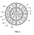
- FIG. 6 is a diagram illustrating still another arrangement example of the internal heating sources and the nozzles.
- the internal heating sources 64a and 64b and the nozzles 66a and 66b are arranged alternately and concentrically.
- the internal heating sources 64a and 64b and the nozzles 66a and 66b arranged on the same circumferences are arranged at equal intervals.
- the internal heating source 64a is arranged at the center of the reactor pipe 20, the nozzles 66a are arranged on the same circumference outside it, and the internal heating sources 64b further outside them and the nozzles 66b still further outside them are arranged on the respective same circumferences.
- a distance between each of the peripheral walls of the internal heating sources 64a and 64b is 2a, and the nozzles 66a are arranged at the midpoint.
- the number of nozzles 66a is half that of the internal heating sources 64b so that an interval b between the nozzles 66a is 2a or more. That is, a nozzle 66a-1 is arranged on a line connecting the center of an internal heating source 64b-1 (See FIG. 6 ) and the center of the internal heating source 64a.
- a nozzle 66a-2 is arranged on a line connecting an internal heating source 64b-3 skipping an internal heating source 64b-2 from the above internal heating source 64b-1 and the center of the internal heating source 64a.
- a diameter of the internal heating source 64a and the number of the internal heating sources 64b are determined so that the distance between the adjacent nozzles 66a is 2a or more.
- Nozzle 66b on the outside are arranged in one to one correspondence with the internal heating sources 64b.
- a distance between an inner peripheral wall of the reactor pipe 20 and a peripheral wall of the internal heating source 64b on the outside is 2a, and the nozzle 66b is arranged at the midpoint.
- the number of the internal heating sources 64b and diameters of the internal heating sources 64a and 64b are determined so that the distance b between the adjacent nozzles is 2a or more.
Landscapes
- Chemical & Material Sciences (AREA)
- Engineering & Computer Science (AREA)
- Nanotechnology (AREA)
- Organic Chemistry (AREA)
- Materials Engineering (AREA)
- Crystallography & Structural Chemistry (AREA)
- Chemical Kinetics & Catalysis (AREA)
- Physics & Mathematics (AREA)
- Condensed Matter Physics & Semiconductors (AREA)
- General Physics & Mathematics (AREA)
- Manufacturing & Machinery (AREA)
- Inorganic Chemistry (AREA)
- Composite Materials (AREA)
- Carbon And Carbon Compounds (AREA)
- Physical Or Chemical Processes And Apparatus (AREA)
Abstract
Description
- The present invention relates to a structure of a device for carbon nanotubes synthesis.
- As a method for synthesizing carbon nanotubes, a vapor-phase flow method is known. In this method, a material containing a carbon source, a catalyst and the like is supplied into a heated cylindrical reactor pipe, and carbon nanotubes are made to grow in a state floating in the reactor pipe. The carbon nanotube has attracted attention recently as a new material having new possibilities, and industrial uses thereof have been examined. For industrial use, increase of a production amount is in demand.
-
Patent Document 1 discloses a technique for increasing a yield by enlarging a diameter of a lab level reactor pipe and by increasing the number of material injection nozzles. In that case, in order to eliminate unevenness in temperature inside the reactor pipe, an internal heating source is arranged inside the reactor pipe.
Patent Document 1: Japanese Patent Laid-Open Publication No.2005-41752 - In the production of carbon nanotubes, in addition to the production amount, there is a demand for improved yield, that is, an increase of a ratio of the carbon nanotubes having a desired structure. If single walled carbon nanotubes are to be obtained, for example, deposition of multiwalled carbon nanotubes, amorphous carbons and the like should be suppressed. It is an advantage of the present invention to provide a synthesizer with higher production amount and yield.
- A carbon nanotube synthesizer of the present invention includes a cylindrical reactor pipe heated by a heating device so as to be a cylindrical heating element, a tubular or columnar internal heating source arranged inside the reactor pipe so as to have an axis parallel with the axis of the reactor pipe, and a plurality of material injection nozzles for supplying a material and a carrier gas into the reactor pipe along a direction parallel with the axis of the reactor pipe. The carrier gas is supplied so as to surround the periphery of the injected material. The nozzles are arranged so that a distance between one of the nozzles and two heating bodies (the circumference heating element or the internal heating source) closest to this nozzle is a first distance, and a distance from this nozzle to a nozzle closest to this nozzle is a second distance, which is twice or more of the first distance.
- According to the present invention, a yield of the carbon nanotube synthesizer can be improved.
-
-
FIG. 1 is a diagram illustrating an outline configuration of a carbon nanotube producing device of this embodiment; -
FIG. 2 is a diagram illustrating an arrangement example of the nozzles and an internal heating source; -
FIG. 3 is a diagram illustrating an arrangement example of the nozzles and the internal heating sources; -
FIG. 4 is a diagram illustrating an arrangement example of the nozzles and the internal heating sources; -
FIG. 5 is a diagram illustrating an arrangement example of the nozzles and the internal heating sources and -
FIG. 6 is a diagram illustrating an arrangement example of the nozzles and the internal heating source. - 10 carbon nanotube producing device, 16 synthesizer, 20 reactor pipe (circumference heating element), 24, 34, 44, 54a, 54b, 64a, 64b internal heating source, 26, 36, 46, 56a, 56b, 66a, 66b material injection nozzle.
- An embodiment of the present invention will be described below referring to the attached drawings.
FIG. 1 is an outline configuration diagram of a carbonnanotube producing device 10. The carbonnanotube producing device 10 includes amaterial supplying device 12 for supplying a material, a carriergas supplying device 14 for supplying a carrier gas, asynthesizer 16 for synthesizing carbon nanotubes from the material, and acollecting device 18 for collecting the synthesized carbon nanotubes. The material includes a carbon source, a catalyst, and auxiliaries. The carrier gas does not directly relate to synthesis of the carbon nanotubes but is used for adjusting a material reaction condition inside thesynthesizer 16. - The
synthesizer 16 includes a substantiallycylindrical reactor pipe 20 and aheating device 22 arranged so as to surround thereactor pipe 20. Thereactor pipe 20 is arranged so that its cylindrical axis is along the vertical direction, that is, a direction in which gravity acts. Here, the concept of "gravity" includes pseudo gravity caused by an inertial force such as a centrifugal force in addition to the intermoleculer force. Thereactor pipe 20 is heated by theheating device 22 so as to have a high temperature and to become a circumference heating element heating the inside wall of the pipe. In thereactor pipe 20, aninternal heating source 24 is further arranged. Theinternal heating source 24 has a tubular, columnar, or preferably circular tubular or circular cylinder shape, and is arranged so that its axis is parallel to the cylindrical axis of thereactor pipe 20. In this embodiment, a circular cylinder shape is employed. The concept of "parallelism" in this case also includes a coaxial arrangement of thereactor pipe 20 and theinternal heating source 24. The internal heating source is arranged in single or in plural, and the arrangement will be described later. As theheating device 22 and theinternal heating source 24, for example, a heating element using an electric resistunce can be used. - In the
reactor pipe 20, a plurality ofnozzles 26 for supplying the material and the carrier gas are arranged. The material has a transition metal compound to be a catalyst and a reaction auxiliary added to a solvent containing a carbon source with prior adjustment, and is supplied by thematerial supplying device 12 to thenozzles 26 through a pump. Moreover, the material is injected into thereactor pipe 20 as fine droplet particles from a distal end of thenozzle 26. The carrier gas is supplied by the carriergas supplying device 14 into thereactor pipe 20 from the vicinity of thenozzles 26 while an appropriate flow rate is controlled by a mass flow meter. A distal end portion of thenozzle 26 is configured to supply the material and the carrier gas separately into the reactor pipe. The material is injected from the center of the distal end of thenozzle 26, while the carrier gas is supplied from the peripheral part of the distal end, and a resulting ring-shaped flow with a sectional shape surrounding the material droplet flows through the reactor pipe. - The material droplets receive heat from the circumference heating element and the internal heating source while flowing down through the
reactor pipe 20, and carbon nanotubes are synthesized by actions of carbon generated by thermal decomposition of the carbon source, metal particles generated by thermal decomposition of the transition metal compound, and the auxiliary. From a bottom portion of thereactor pipe 20, a discharged gas containing the synthesized carbon nanotubes is discharged and fed to thecollecting device 18. At thecollecting device 18, the carbon nanotubes are separated from the discharged gas and collected. - Subsequently, arrangement of the
internal heating sources 24 and thenozzles 26 will be described. In each of the following arrangement examples, arrangement in a section orthogonal to the axis of thereactor pipe 20 is shown.FIG. 2 is a transverse cross section of thesynthesizer 16 inFIG. 1 . An example of a single unit of theinternal heating source 24 and 6 units of thenozzles 26 is shown. Theinternal heating source 24 is arranged coaxially with thereactor pipe 20, which is a circumference heating element. Thenozzles 26 are arranged on acircle 28 at an equal distance a from an inner wall of thereactor pipe 20 and a peripheral surface of theinternal heating source 24. Moreover, thenozzles 26 are arranged so that a distance between the adjacent nozzles is a distance b, which is approximately twice the distance a. The distance a is a distance between the nozzle and the reactor pipe inner wall surface acquired from the synthesizer in which a single nozzle is disposed at the center of a reactor pipe so that synthesis of high yield and high quality carbon nanotubes is to be realized. The arrangement of the internal heating source and the nozzle is considered so that at least two heating bodies (the reactor pipe and the internal heating source) at this distance a are provided for one nozzle, or more preferably, the arrangement in which the nozzle is sandwiched by two heating sources is considered. There are cases in which the two heating sources are the reactor pipe and a single unit of the internal heating source, and the two heating sources are the reactor pipe and two internal heating sources. Also, the distance a is considered to be a distance with which flows of the material and the carrier gas supplied from theadjacent nozzles 26 do not interfere with the reactor pipe inner wall. In the example inFIG. 2 , by increasing the distance b to approximately twice the distance a, the flows of the material and the carrier gas injected from the adjacent nozzles can be prevented from interfering with each other. From the viewpoint that the flows are prevented from interfering with each other, it is understood that the distance b is preferably twice or more the distance a. The greater the number of arranged nozzles, the more the yield can be increased, and from this viewpoint, the shorter distance b is the better, and the distance b is preferably set at twice the distance a. In order to achieve the distance b of twice the distance a, a diameter of theinternal heating source 24 is adjusted. -
FIG. 3 is a diagram illustrating another arrangement example of the internal heating sources and nozzles. There are arranged three units of aninternal heating sources 34 and six units of anozzles 36. A circle formed by the inner wall of thereactor pipe 20 is divided into three sectors. At the center of acircle 32 inscribed inradiuses 30 of both ends of the sector, the center of theinternal heating source 34 is arranged. A distance between thecircle 32 and theinternal heating source 34 is made a, and thecircle 32 passes through a midpoint between the peripheral wall of theinternal heating source 34 and the inner wall of thereactor pipe 20. Thenozzles 36 are arranged at contacts between thecircles 32, and a diameter of theinternal heating source 34 is determined so that the distance b between the nozzles is twice or more the distance a, and the shortest distance between the peripheral wall of theinternal heating source 34 and the internal wall of thereactor pipe 20 is 2a. From another viewpoint, the arrangement inFIG. 3 is as follows. The threeinternal heating sources 34 are arranged on a single circumference concentric to thereactor pipe 20. For oneinternal heating source 34, onenozzle 36 is arranged between that and thereactor pipe 20, and one nozzle each corresponds to each of the three internal heating source. Also, between the adjacentinternal heating sources 34, onenozzle 36 is arranged, and the three nozzles in total are arranged. -
FIG. 4 is a diagram illustrating still another arrangement example of the internal heating sources and the nozzles. There are arranged four units ofinternal heating sources 44 and eight units of thenozzles 46. The arranging method is basically the same as inFIG. 3 . InFIG. 3 , the circle formed by the inner wall of thereactor pipe 20 is equally divided into three parts, but in the example inFIG. 4 , it is equally divided into four parts. Then, theinternal heating source 44 is arranged so that its center is located at the center of acircle 42 inscribed inradiuses 40 of both ends of the sector. A distance between thecircle 42 and theinternal heating source 44 is made a, and thecircle 42 passes through the midpoint between the peripheral wall of theinternal heating source 44 and the inner wall of thereactor pipe 20. A diameter of theinternal heating source 44 is determined so that thenozzle 46 is arranged at a contact between thecircles 42, the distance b between the nozzles is twice or more the distance a, and the shortest distance between the peripheral wall of theinternal heating source 44 and the inner wall of thereactor pipe 20 is 2a. Similarly, the number of theinternal heating sources 44 can be increased. From another viewpoint, the arrangement inFIG. 4 is as follows. The fourinternal heating sources 44 are arranged on a single circumference concentric to thereactor pipe 20. For oneinternal heating source 44, onenozzle 46 is arranged between that and thereactor pipe 20, and one nozzle each corresponds to each of the four internal heating sources. Also, between the adjacentinternal heating sources 44, onenozzle 46 is arranged, and the four nozzles in total are arranged. - The arrangement examples shown in
FIGS. 3 and4 are examples in which a plurality ofinternal heating sources FIG. 5 is an example in which six units of theinternal heating source 54b are arranged on a single circumference and moreover, an anotherinternal heating source 54a is arranged inside them. Arrangement of the sixinternal heating source 54b andnozzles 56a can be determined similarly to the arrangement examples inFIGS. 3 and4 . With the same center as that of thereactor pipe 20, acircle 57 inscribed in acircle 52 is determined. A diameter of theinternal heating source 54b can be determined so that a distance between thecircle 57 and the peripheral wall becomes a. If there are six units of theinternal heating sources 54b arranged on the single circumference, the diameters of theinternal heating sources nozzle 56b is also arranged at the point of contact between thecircle 52 and thecircle 57. From another viewpoint, the arrangement inFIG. 5 is as follows. Theinternal heating source 54a is arranged coaxially with thereactor pipe 20. The sixinternal heating sources 54b are arranged on a single circumference concentric to thereactor pipe 20. One nozzle each is arranged between each of the sixinternal heating sources 54b arranged on the circumference and thereactor pipe 20, that is, six nozzles in total are arranged, one nozzle each is arranged between each of the sixinternal heating source 54b and theinternal heating source 54a at the center, that is, six nozzles in total are arranged, and moreover, one each is arranged between the adjacentinternal heating source 54b arranged on the single circumference, that is, six nozzles in total are arranged. -
FIG. 6 is a diagram illustrating still another arrangement example of the internal heating sources and the nozzles. In this example, theinternal heating sources nozzles internal heating sources nozzles internal heating source 64a is arranged at the center of thereactor pipe 20, thenozzles 66a are arranged on the same circumference outside it, and theinternal heating sources 64b further outside them and thenozzles 66b still further outside them are arranged on the respective same circumferences. A distance between each of the peripheral walls of theinternal heating sources nozzles 66a are arranged at the midpoint. The number ofnozzles 66a is half that of theinternal heating sources 64b so that an interval b between thenozzles 66a is 2a or more. That is, anozzle 66a-1 is arranged on a line connecting the center of aninternal heating source 64b-1 (SeeFIG. 6 ) and the center of theinternal heating source 64a. Anozzle 66a-2 is arranged on a line connecting aninternal heating source 64b-3 skipping aninternal heating source 64b-2 from the aboveinternal heating source 64b-1 and the center of theinternal heating source 64a. A diameter of theinternal heating source 64a and the number of theinternal heating sources 64b are determined so that the distance between theadjacent nozzles 66a is 2a or more. -
Nozzle 66b on the outside are arranged in one to one correspondence with theinternal heating sources 64b. A distance between an inner peripheral wall of thereactor pipe 20 and a peripheral wall of theinternal heating source 64b on the outside is 2a, and thenozzle 66b is arranged at the midpoint. As for thenozzle 66b, too, the number of theinternal heating sources 64b and diameters of theinternal heating sources
Claims (6)
- An apparatus for carbon nanotube synthesis, comprising:a cylindrical reactor pipe heated by a heating device so as to become a circumference heating element;at least one tubular or columnar internal heating sources arranged in said reactor pipe and having an axis parallel to an axis of said reactor pipe; anda plurality of nozzles for injecting a material and a carrier gas into the reactor pipe along a direction parallel to the axis of said reactor pipe, in which the carrier gas is supplied so as to surround the periphery of the supplied material, whereina distance between said nozzle and two heating bodies, among the circumference heating element and the internal sources, that are closest to this nozzle is a first distance, and a distance from the nozzle to a nozzle closest to this nozzle is a second distance, which is twice or more said first distance.
- The carbon nanotube synthesizer according to claim 1, wherein said reactor pipe and one unit of said internal heating source are arranged coaxially.
- The carbon nanotube synthesizer according to claim 1, wherein
a plurality of said internal heating sources are arranged on a single circumference concentric to said reactor pipe; and
said nozzles are arranged one each between each of said internal heating sources and said reactor pipe and one each between said adjacent internal heating sources. - The carbon nanotube synthesizer according to claim 3, wherein
the number of said internal heating sources is three. - The carbon nanotube synthesizer according to claim 3, wherein
the number of said internal heating sources is four. - The carbon nanotube synthesizer according to claim 1, wherein
one of said internal heating sources is arranged coaxially with said reactor pipe and six units are arranged on a single circumference concentric to said reactor pipe; and
said nozzles are arranged one each between each of the internal heating sources arranged on said circumference and said reactor pipe, one each between the internal heating sources arranged coaxially with said reactor pipe, and one each between the adjacent heating sources arranged on said circumference.
Applications Claiming Priority (2)
| Application Number | Priority Date | Filing Date | Title |
|---|---|---|---|
| JP2008020968 | 2008-01-31 | ||
| PCT/JP2008/070506 WO2009096077A1 (en) | 2008-01-31 | 2008-11-11 | Carbon nanotube synthesizer |
Publications (3)
| Publication Number | Publication Date |
|---|---|
| EP2239227A1 true EP2239227A1 (en) | 2010-10-13 |
| EP2239227A4 EP2239227A4 (en) | 2012-05-09 |
| EP2239227B1 EP2239227B1 (en) | 2013-08-14 |
Family
ID=40912439
Family Applications (1)
| Application Number | Title | Priority Date | Filing Date |
|---|---|---|---|
| EP08871754.1A Not-in-force EP2239227B1 (en) | 2008-01-31 | 2008-11-11 | Carbon nanotube synthesizer |
Country Status (10)
| Country | Link |
|---|---|
| US (1) | US8303903B2 (en) |
| EP (1) | EP2239227B1 (en) |
| JP (1) | JP5250567B2 (en) |
| KR (1) | KR20100108506A (en) |
| CN (1) | CN101848860A (en) |
| CA (1) | CA2703084A1 (en) |
| IL (1) | IL205103A0 (en) |
| RU (1) | RU2010115226A (en) |
| TW (1) | TW200932672A (en) |
| WO (1) | WO2009096077A1 (en) |
Cited By (1)
| Publication number | Priority date | Publication date | Assignee | Title |
|---|---|---|---|---|
| CN102963124A (en) * | 2012-11-29 | 2013-03-13 | 中国科学院苏州纳米技术与纳米仿生研究所 | Gas jet printing device and jet printing method |
Families Citing this family (4)
| Publication number | Priority date | Publication date | Assignee | Title |
|---|---|---|---|---|
| KR102059224B1 (en) * | 2015-11-27 | 2019-12-24 | 주식회사 엘지화학 | Device for manufacturing carbon nanotube aggregates and carbon nanotube aggregates manufactured using same |
| KR102358843B1 (en) | 2019-12-19 | 2022-02-08 | 한국과학기술연구원 | A continuous carbon nanotube manufacturing apparatus and method |
| CN113996263B (en) * | 2021-10-26 | 2023-04-07 | 鞍山七彩化学股份有限公司 | Heterogeneous reactor |
| CN119040852A (en) * | 2024-08-22 | 2024-11-29 | 江西铜业技术研究院有限公司 | Preparation device and method for producing carbon nano tube by floating chemical vapor deposition method |
Family Cites Families (10)
| Publication number | Priority date | Publication date | Assignee | Title |
|---|---|---|---|---|
| DE1667036A1 (en) * | 1967-01-02 | 1971-05-27 | Bayer Ag | Method and device for direct electrical heating of gases or gaseous substances |
| JP3637177B2 (en) * | 1996-04-03 | 2005-04-13 | 日機装株式会社 | Vapor growth carbon fiber production equipment |
| JP4405650B2 (en) * | 1999-07-13 | 2010-01-27 | 日機装株式会社 | Carbonaceous nanotube, fiber assembly, and method for producing carbonaceous nanotube |
| US6790426B1 (en) | 1999-07-13 | 2004-09-14 | Nikkiso Co., Ltd. | Carbonaceous nanotube, nanotube aggregate, method for manufacturing a carbonaceous nanotube |
| JP4132480B2 (en) | 1999-10-13 | 2008-08-13 | 日機装株式会社 | Carbon nanofiber sliver thread and method for producing the same |
| JP4196017B2 (en) * | 2001-08-23 | 2008-12-17 | 日機装株式会社 | Carbonaceous nanofiber and method for producing the same |
| JP4000257B2 (en) * | 2001-12-26 | 2007-10-31 | 日機装株式会社 | Post-treatment method for carbon nanofiber and method for producing graphitized carbon nanofiber |
| JP4394981B2 (en) * | 2003-05-02 | 2010-01-06 | 日機装株式会社 | Raw material gas supply nozzle, carbon nanofiber manufacturing apparatus, and carbon nanofiber manufacturing method |
| JP4120812B2 (en) | 2003-05-28 | 2008-07-16 | 清水建設株式会社 | Floating body damping device and floating body seismic isolation structure equipped with floating body damping device |
| JP3810394B2 (en) * | 2003-07-25 | 2006-08-16 | 日機装株式会社 | Reaction tube equipment with internal heating element |
-
2008
- 2008-11-11 RU RU2010115226/05A patent/RU2010115226A/en unknown
- 2008-11-11 JP JP2009551399A patent/JP5250567B2/en not_active Expired - Fee Related
- 2008-11-11 CN CN200880114805A patent/CN101848860A/en active Pending
- 2008-11-11 CA CA2703084A patent/CA2703084A1/en not_active Abandoned
- 2008-11-11 WO PCT/JP2008/070506 patent/WO2009096077A1/en not_active Ceased
- 2008-11-11 US US12/740,454 patent/US8303903B2/en not_active Expired - Fee Related
- 2008-11-11 KR KR1020107007472A patent/KR20100108506A/en not_active Withdrawn
- 2008-11-11 EP EP08871754.1A patent/EP2239227B1/en not_active Not-in-force
- 2008-12-08 TW TW097147590A patent/TW200932672A/en unknown
-
2010
- 2010-04-15 IL IL205103A patent/IL205103A0/en unknown
Cited By (2)
| Publication number | Priority date | Publication date | Assignee | Title |
|---|---|---|---|---|
| CN102963124A (en) * | 2012-11-29 | 2013-03-13 | 中国科学院苏州纳米技术与纳米仿生研究所 | Gas jet printing device and jet printing method |
| CN102963124B (en) * | 2012-11-29 | 2015-06-03 | 中国科学院苏州纳米技术与纳米仿生研究所 | Gas jet printing device and jet printing method |
Also Published As
| Publication number | Publication date |
|---|---|
| CN101848860A (en) | 2010-09-29 |
| EP2239227B1 (en) | 2013-08-14 |
| EP2239227A4 (en) | 2012-05-09 |
| RU2010115226A (en) | 2012-03-10 |
| JPWO2009096077A1 (en) | 2011-05-26 |
| TW200932672A (en) | 2009-08-01 |
| US20100260650A1 (en) | 2010-10-14 |
| JP5250567B2 (en) | 2013-07-31 |
| IL205103A0 (en) | 2010-11-30 |
| CA2703084A1 (en) | 2009-08-06 |
| US8303903B2 (en) | 2012-11-06 |
| WO2009096077A1 (en) | 2009-08-06 |
| KR20100108506A (en) | 2010-10-07 |
Similar Documents
| Publication | Publication Date | Title |
|---|---|---|
| EP2239227B1 (en) | Carbon nanotube synthesizer | |
| US8557190B2 (en) | Carbon nanotube synthesis process apparatus | |
| KR101651315B1 (en) | Fluidized bed reactor and preparatio of carbon nanostructures using same | |
| KR102043009B1 (en) | Apparatus of vapor phase-synthesis for carbonnanotubes | |
| JP7089108B2 (en) | Collection equipment and manufacturing system | |
| KR20020026663A (en) | Apparatus of vapor phase-synthesis for carbon nanotubes or carbon nanofibers and synthesizing method of using the same | |
| TW201236104A (en) | Chuck for chemical vapor deposition systems and related methods therefor | |
| HK1143799A (en) | Carbon nanotube synthesizer | |
| JP3810394B2 (en) | Reaction tube equipment with internal heating element | |
| JP4394981B2 (en) | Raw material gas supply nozzle, carbon nanofiber manufacturing apparatus, and carbon nanofiber manufacturing method | |
| KR101590110B1 (en) | Manufacturing apparatus for carbon nano tube | |
| KR101248545B1 (en) | Reaction tube with mixing piece of carbon nano tubes fabrication apparatus | |
| JPH0978360A (en) | Method for producing vapor grown carbon fiber | |
| KR101082833B1 (en) | Apparatus for synthesizing carbon nano tube | |
| KR101350198B1 (en) | Method and apparatus of collecting carbon nano tube | |
| CN118142443B (en) | Trickle bed reactor and method for preparing benzyl amine by using same | |
| JP2019098323A (en) | Reaction apparatus | |
| KR100844456B1 (en) | Carbon nanotube manufacturing apparatus and manufacturing method | |
| US20130209347A1 (en) | Gas to gas heat exchanger | |
| KR20110055159A (en) | Catalyst manufacturing apparatus for carbon nanotube synthesis | |
| JP2009174092A (en) | Method for producing carbon fiber | |
| JP4391900B2 (en) | Carbon nanofiber production equipment | |
| KR20090047098A (en) | Shower head device for carbon nanotube manufacturing | |
| JP2013136476A (en) | Nanocarbon production apparatus | |
| JP2007039838A (en) | Fine carbon fiber production apparatus and production method thereof |
Legal Events
| Date | Code | Title | Description |
|---|---|---|---|
| PUAI | Public reference made under article 153(3) epc to a published international application that has entered the european phase |
Free format text: ORIGINAL CODE: 0009012 |
|
| 17P | Request for examination filed |
Effective date: 20100409 |
|
| AK | Designated contracting states |
Kind code of ref document: A1 Designated state(s): AT BE BG CH CY CZ DE DK EE ES FI FR GB GR HR HU IE IS IT LI LT LU LV MC MT NL NO PL PT RO SE SI SK TR |
|
| AX | Request for extension of the european patent |
Extension state: AL BA MK RS |
|
| RIN1 | Information on inventor provided before grant (corrected) |
Inventor name: MURAI, TAKEJI Inventor name: NAKAGAWA, YUZO Inventor name: SHIRAKI, SHUICHI |
|
| REG | Reference to a national code |
Ref country code: HK Ref legal event code: DE Ref document number: 1143799 Country of ref document: HK |
|
| DAX | Request for extension of the european patent (deleted) | ||
| A4 | Supplementary search report drawn up and despatched |
Effective date: 20120405 |
|
| RIC1 | Information provided on ipc code assigned before grant |
Ipc: C01B 31/02 20060101AFI20120330BHEP Ipc: B01J 19/24 20060101ALI20120330BHEP Ipc: B01J 4/00 20060101ALI20120330BHEP |
|
| 17Q | First examination report despatched |
Effective date: 20121105 |
|
| GRAP | Despatch of communication of intention to grant a patent |
Free format text: ORIGINAL CODE: EPIDOSNIGR1 |
|
| RIC1 | Information provided on ipc code assigned before grant |
Ipc: B01J 19/24 20060101ALI20130306BHEP Ipc: B82Y 40/00 20110101ALI20130306BHEP Ipc: B01J 4/00 20060101ALI20130306BHEP Ipc: C01B 31/02 20060101AFI20130306BHEP |
|
| RIN1 | Information on inventor provided before grant (corrected) |
Inventor name: SHIRAKI, SHUICHI Inventor name: MURAI, TAKEJI Inventor name: NAKAGAWA, YUZO |
|
| GRAS | Grant fee paid |
Free format text: ORIGINAL CODE: EPIDOSNIGR3 |
|
| GRAA | (expected) grant |
Free format text: ORIGINAL CODE: 0009210 |
|
| AK | Designated contracting states |
Kind code of ref document: B1 Designated state(s): AT BE BG CH CY CZ DE DK EE ES FI FR GB GR HR HU IE IS IT LI LT LU LV MC MT NL NO PL PT RO SE SI SK TR |
|
| REG | Reference to a national code |
Ref country code: GB Ref legal event code: FG4D |
|
| REG | Reference to a national code |
Ref country code: AT Ref legal event code: REF Ref document number: 626699 Country of ref document: AT Kind code of ref document: T Effective date: 20130815 Ref country code: CH Ref legal event code: EP |
|
| REG | Reference to a national code |
Ref country code: IE Ref legal event code: FG4D |
|
| REG | Reference to a national code |
Ref country code: DE Ref legal event code: R096 Ref document number: 602008026874 Country of ref document: DE Effective date: 20131010 |
|
| REG | Reference to a national code |
Ref country code: NL Ref legal event code: VDEP Effective date: 20130814 Ref country code: AT Ref legal event code: MK05 Ref document number: 626699 Country of ref document: AT Kind code of ref document: T Effective date: 20130814 |
|
| REG | Reference to a national code |
Ref country code: LT Ref legal event code: MG4D |
|
| PG25 | Lapsed in a contracting state [announced via postgrant information from national office to epo] |
Ref country code: NO Free format text: LAPSE BECAUSE OF FAILURE TO SUBMIT A TRANSLATION OF THE DESCRIPTION OR TO PAY THE FEE WITHIN THE PRESCRIBED TIME-LIMIT Effective date: 20131114 Ref country code: HR Free format text: LAPSE BECAUSE OF FAILURE TO SUBMIT A TRANSLATION OF THE DESCRIPTION OR TO PAY THE FEE WITHIN THE PRESCRIBED TIME-LIMIT Effective date: 20130814 Ref country code: AT Free format text: LAPSE BECAUSE OF FAILURE TO SUBMIT A TRANSLATION OF THE DESCRIPTION OR TO PAY THE FEE WITHIN THE PRESCRIBED TIME-LIMIT Effective date: 20130814 Ref country code: PT Free format text: LAPSE BECAUSE OF FAILURE TO SUBMIT A TRANSLATION OF THE DESCRIPTION OR TO PAY THE FEE WITHIN THE PRESCRIBED TIME-LIMIT Effective date: 20131216 Ref country code: SE Free format text: LAPSE BECAUSE OF FAILURE TO SUBMIT A TRANSLATION OF THE DESCRIPTION OR TO PAY THE FEE WITHIN THE PRESCRIBED TIME-LIMIT Effective date: 20130814 Ref country code: IS Free format text: LAPSE BECAUSE OF FAILURE TO SUBMIT A TRANSLATION OF THE DESCRIPTION OR TO PAY THE FEE WITHIN THE PRESCRIBED TIME-LIMIT Effective date: 20131214 Ref country code: CY Free format text: LAPSE BECAUSE OF FAILURE TO SUBMIT A TRANSLATION OF THE DESCRIPTION OR TO PAY THE FEE WITHIN THE PRESCRIBED TIME-LIMIT Effective date: 20130911 Ref country code: LT Free format text: LAPSE BECAUSE OF FAILURE TO SUBMIT A TRANSLATION OF THE DESCRIPTION OR TO PAY THE FEE WITHIN THE PRESCRIBED TIME-LIMIT Effective date: 20130814 |
|
| PG25 | Lapsed in a contracting state [announced via postgrant information from national office to epo] |
Ref country code: FI Free format text: LAPSE BECAUSE OF FAILURE TO SUBMIT A TRANSLATION OF THE DESCRIPTION OR TO PAY THE FEE WITHIN THE PRESCRIBED TIME-LIMIT Effective date: 20130814 Ref country code: PL Free format text: LAPSE BECAUSE OF FAILURE TO SUBMIT A TRANSLATION OF THE DESCRIPTION OR TO PAY THE FEE WITHIN THE PRESCRIBED TIME-LIMIT Effective date: 20130814 Ref country code: SI Free format text: LAPSE BECAUSE OF FAILURE TO SUBMIT A TRANSLATION OF THE DESCRIPTION OR TO PAY THE FEE WITHIN THE PRESCRIBED TIME-LIMIT Effective date: 20130814 Ref country code: BE Free format text: LAPSE BECAUSE OF FAILURE TO SUBMIT A TRANSLATION OF THE DESCRIPTION OR TO PAY THE FEE WITHIN THE PRESCRIBED TIME-LIMIT Effective date: 20130814 Ref country code: GR Free format text: LAPSE BECAUSE OF FAILURE TO SUBMIT A TRANSLATION OF THE DESCRIPTION OR TO PAY THE FEE WITHIN THE PRESCRIBED TIME-LIMIT Effective date: 20131115 Ref country code: LV Free format text: LAPSE BECAUSE OF FAILURE TO SUBMIT A TRANSLATION OF THE DESCRIPTION OR TO PAY THE FEE WITHIN THE PRESCRIBED TIME-LIMIT Effective date: 20130814 |
|
| PG25 | Lapsed in a contracting state [announced via postgrant information from national office to epo] |
Ref country code: CY Free format text: LAPSE BECAUSE OF FAILURE TO SUBMIT A TRANSLATION OF THE DESCRIPTION OR TO PAY THE FEE WITHIN THE PRESCRIBED TIME-LIMIT Effective date: 20130814 |
|
| PG25 | Lapsed in a contracting state [announced via postgrant information from national office to epo] |
Ref country code: EE Free format text: LAPSE BECAUSE OF FAILURE TO SUBMIT A TRANSLATION OF THE DESCRIPTION OR TO PAY THE FEE WITHIN THE PRESCRIBED TIME-LIMIT Effective date: 20130814 Ref country code: SK Free format text: LAPSE BECAUSE OF FAILURE TO SUBMIT A TRANSLATION OF THE DESCRIPTION OR TO PAY THE FEE WITHIN THE PRESCRIBED TIME-LIMIT Effective date: 20130814 Ref country code: NL Free format text: LAPSE BECAUSE OF FAILURE TO SUBMIT A TRANSLATION OF THE DESCRIPTION OR TO PAY THE FEE WITHIN THE PRESCRIBED TIME-LIMIT Effective date: 20130814 Ref country code: RO Free format text: LAPSE BECAUSE OF FAILURE TO SUBMIT A TRANSLATION OF THE DESCRIPTION OR TO PAY THE FEE WITHIN THE PRESCRIBED TIME-LIMIT Effective date: 20130814 Ref country code: CZ Free format text: LAPSE BECAUSE OF FAILURE TO SUBMIT A TRANSLATION OF THE DESCRIPTION OR TO PAY THE FEE WITHIN THE PRESCRIBED TIME-LIMIT Effective date: 20130814 Ref country code: DK Free format text: LAPSE BECAUSE OF FAILURE TO SUBMIT A TRANSLATION OF THE DESCRIPTION OR TO PAY THE FEE WITHIN THE PRESCRIBED TIME-LIMIT Effective date: 20130814 |
|
| PG25 | Lapsed in a contracting state [announced via postgrant information from national office to epo] |
Ref country code: ES Free format text: LAPSE BECAUSE OF FAILURE TO SUBMIT A TRANSLATION OF THE DESCRIPTION OR TO PAY THE FEE WITHIN THE PRESCRIBED TIME-LIMIT Effective date: 20130814 Ref country code: IT Free format text: LAPSE BECAUSE OF FAILURE TO SUBMIT A TRANSLATION OF THE DESCRIPTION OR TO PAY THE FEE WITHIN THE PRESCRIBED TIME-LIMIT Effective date: 20130814 |
|
| PLBE | No opposition filed within time limit |
Free format text: ORIGINAL CODE: 0009261 |
|
| STAA | Information on the status of an ep patent application or granted ep patent |
Free format text: STATUS: NO OPPOSITION FILED WITHIN TIME LIMIT |
|
| REG | Reference to a national code |
Ref country code: CH Ref legal event code: PL |
|
| 26N | No opposition filed |
Effective date: 20140515 |
|
| PG25 | Lapsed in a contracting state [announced via postgrant information from national office to epo] |
Ref country code: LI Free format text: LAPSE BECAUSE OF NON-PAYMENT OF DUE FEES Effective date: 20131130 Ref country code: CH Free format text: LAPSE BECAUSE OF NON-PAYMENT OF DUE FEES Effective date: 20131130 Ref country code: MC Free format text: LAPSE BECAUSE OF FAILURE TO SUBMIT A TRANSLATION OF THE DESCRIPTION OR TO PAY THE FEE WITHIN THE PRESCRIBED TIME-LIMIT Effective date: 20130814 |
|
| REG | Reference to a national code |
Ref country code: IE Ref legal event code: MM4A |
|
| REG | Reference to a national code |
Ref country code: DE Ref legal event code: R097 Ref document number: 602008026874 Country of ref document: DE Effective date: 20140515 |
|
| PG25 | Lapsed in a contracting state [announced via postgrant information from national office to epo] |
Ref country code: IE Free format text: LAPSE BECAUSE OF NON-PAYMENT OF DUE FEES Effective date: 20131111 |
|
| PG25 | Lapsed in a contracting state [announced via postgrant information from national office to epo] |
Ref country code: TR Free format text: LAPSE BECAUSE OF FAILURE TO SUBMIT A TRANSLATION OF THE DESCRIPTION OR TO PAY THE FEE WITHIN THE PRESCRIBED TIME-LIMIT Effective date: 20130814 |
|
| PG25 | Lapsed in a contracting state [announced via postgrant information from national office to epo] |
Ref country code: BG Free format text: LAPSE BECAUSE OF FAILURE TO SUBMIT A TRANSLATION OF THE DESCRIPTION OR TO PAY THE FEE WITHIN THE PRESCRIBED TIME-LIMIT Effective date: 20130814 Ref country code: HU Free format text: LAPSE BECAUSE OF FAILURE TO SUBMIT A TRANSLATION OF THE DESCRIPTION OR TO PAY THE FEE WITHIN THE PRESCRIBED TIME-LIMIT; INVALID AB INITIO Effective date: 20081111 Ref country code: LU Free format text: LAPSE BECAUSE OF NON-PAYMENT OF DUE FEES Effective date: 20131111 |
|
| PG25 | Lapsed in a contracting state [announced via postgrant information from national office to epo] |
Ref country code: MT Free format text: LAPSE BECAUSE OF FAILURE TO SUBMIT A TRANSLATION OF THE DESCRIPTION OR TO PAY THE FEE WITHIN THE PRESCRIBED TIME-LIMIT Effective date: 20130814 |
|
| REG | Reference to a national code |
Ref country code: FR Ref legal event code: PLFP Year of fee payment: 8 |
|
| REG | Reference to a national code |
Ref country code: FR Ref legal event code: PLFP Year of fee payment: 9 |
|
| REG | Reference to a national code |
Ref country code: DE Ref legal event code: R079 Ref document number: 602008026874 Country of ref document: DE Free format text: PREVIOUS MAIN CLASS: C01B0031020000 Ipc: C01B0032050000 |
|
| PGFP | Annual fee paid to national office [announced via postgrant information from national office to epo] |
Ref country code: DE Payment date: 20161125 Year of fee payment: 9 Ref country code: GB Payment date: 20161124 Year of fee payment: 9 Ref country code: FR Payment date: 20161124 Year of fee payment: 9 |
|
| REG | Reference to a national code |
Ref country code: HK Ref legal event code: WD Ref document number: 1143799 Country of ref document: HK |
|
| REG | Reference to a national code |
Ref country code: DE Ref legal event code: R119 Ref document number: 602008026874 Country of ref document: DE |
|
| GBPC | Gb: european patent ceased through non-payment of renewal fee |
Effective date: 20171111 |
|
| REG | Reference to a national code |
Ref country code: FR Ref legal event code: ST Effective date: 20180731 |
|
| PG25 | Lapsed in a contracting state [announced via postgrant information from national office to epo] |
Ref country code: DE Free format text: LAPSE BECAUSE OF NON-PAYMENT OF DUE FEES Effective date: 20180602 Ref country code: FR Free format text: LAPSE BECAUSE OF NON-PAYMENT OF DUE FEES Effective date: 20171130 |
|
| PG25 | Lapsed in a contracting state [announced via postgrant information from national office to epo] |
Ref country code: GB Free format text: LAPSE BECAUSE OF NON-PAYMENT OF DUE FEES Effective date: 20171111 |