EP2238352B1 - Progressive cavity apparatus with transducer and methods of forming and use - Google Patents
Progressive cavity apparatus with transducer and methods of forming and use Download PDFInfo
- Publication number
- EP2238352B1 EP2238352B1 EP08870229.5A EP08870229A EP2238352B1 EP 2238352 B1 EP2238352 B1 EP 2238352B1 EP 08870229 A EP08870229 A EP 08870229A EP 2238352 B1 EP2238352 B1 EP 2238352B1
- Authority
- EP
- European Patent Office
- Prior art keywords
- stator
- cast material
- sleeve
- transducer
- disposed
- Prior art date
- Legal status (The legal status is an assumption and is not a legal conclusion. Google has not performed a legal analysis and makes no representation as to the accuracy of the status listed.)
- Active
Links
- 230000000750 progressive effect Effects 0.000 title claims description 39
- 238000000034 method Methods 0.000 title claims description 23
- 239000000463 material Substances 0.000 claims description 156
- 239000012858 resilient material Substances 0.000 claims description 41
- 239000012530 fluid Substances 0.000 claims description 19
- 239000011800 void material Substances 0.000 claims description 14
- 229910000808 amorphous metal alloy Inorganic materials 0.000 claims description 2
- 230000000717 retained effect Effects 0.000 claims 1
- 239000004020 conductor Substances 0.000 description 15
- 229910052751 metal Inorganic materials 0.000 description 13
- 239000002184 metal Substances 0.000 description 13
- 229920001971 elastomer Polymers 0.000 description 10
- 239000000806 elastomer Substances 0.000 description 9
- 238000004891 communication Methods 0.000 description 8
- 230000015572 biosynthetic process Effects 0.000 description 7
- 238000005553 drilling Methods 0.000 description 7
- 239000013307 optical fiber Substances 0.000 description 7
- -1 for example Substances 0.000 description 6
- 238000005259 measurement Methods 0.000 description 6
- 238000012544 monitoring process Methods 0.000 description 6
- 238000003780 insertion Methods 0.000 description 5
- 230000037431 insertion Effects 0.000 description 5
- 239000011347 resin Substances 0.000 description 5
- 229920005989 resin Polymers 0.000 description 5
- 229920000642 polymer Polymers 0.000 description 4
- 239000004593 Epoxy Substances 0.000 description 3
- 230000008859 change Effects 0.000 description 3
- 239000003795 chemical substances by application Substances 0.000 description 3
- 238000009826 distribution Methods 0.000 description 3
- 239000013013 elastic material Substances 0.000 description 3
- 238000005516 engineering process Methods 0.000 description 3
- 239000000835 fiber Substances 0.000 description 3
- 239000000945 filler Substances 0.000 description 3
- 230000033001 locomotion Effects 0.000 description 3
- 238000004519 manufacturing process Methods 0.000 description 3
- 230000037361 pathway Effects 0.000 description 3
- 229920001343 polytetrafluoroethylene Polymers 0.000 description 3
- 239000004810 polytetrafluoroethylene Substances 0.000 description 3
- 230000008569 process Effects 0.000 description 3
- OKTJSMMVPCPJKN-UHFFFAOYSA-N Carbon Chemical compound [C] OKTJSMMVPCPJKN-UHFFFAOYSA-N 0.000 description 2
- 229910000831 Steel Inorganic materials 0.000 description 2
- 229910045601 alloy Inorganic materials 0.000 description 2
- 239000000956 alloy Substances 0.000 description 2
- 230000004323 axial length Effects 0.000 description 2
- 238000009530 blood pressure measurement Methods 0.000 description 2
- 239000007767 bonding agent Substances 0.000 description 2
- 229910052799 carbon Inorganic materials 0.000 description 2
- 239000000919 ceramic Substances 0.000 description 2
- 230000006835 compression Effects 0.000 description 2
- 238000007906 compression Methods 0.000 description 2
- 238000001816 cooling Methods 0.000 description 2
- 238000013461 design Methods 0.000 description 2
- 230000005674 electromagnetic induction Effects 0.000 description 2
- 238000002347 injection Methods 0.000 description 2
- 239000007924 injection Substances 0.000 description 2
- 238000003754 machining Methods 0.000 description 2
- 239000013618 particulate matter Substances 0.000 description 2
- 230000001105 regulatory effect Effects 0.000 description 2
- 230000035939 shock Effects 0.000 description 2
- 239000010959 steel Substances 0.000 description 2
- 229920001187 thermosetting polymer Polymers 0.000 description 2
- JOYRKODLDBILNP-UHFFFAOYSA-N Ethyl urethane Chemical compound CCOC(N)=O JOYRKODLDBILNP-UHFFFAOYSA-N 0.000 description 1
- RTAQQCXQSZGOHL-UHFFFAOYSA-N Titanium Chemical compound [Ti] RTAQQCXQSZGOHL-UHFFFAOYSA-N 0.000 description 1
- 239000000853 adhesive Substances 0.000 description 1
- 230000001070 adhesive effect Effects 0.000 description 1
- 229910052782 aluminium Inorganic materials 0.000 description 1
- XAGFODPZIPBFFR-UHFFFAOYSA-N aluminium Chemical compound [Al] XAGFODPZIPBFFR-UHFFFAOYSA-N 0.000 description 1
- 230000000712 assembly Effects 0.000 description 1
- 238000000429 assembly Methods 0.000 description 1
- 230000005540 biological transmission Effects 0.000 description 1
- 230000015556 catabolic process Effects 0.000 description 1
- 238000005520 cutting process Methods 0.000 description 1
- 230000007547 defect Effects 0.000 description 1
- 238000006731 degradation reaction Methods 0.000 description 1
- 230000001419 dependent effect Effects 0.000 description 1
- 238000001514 detection method Methods 0.000 description 1
- 238000006073 displacement reaction Methods 0.000 description 1
- 230000005611 electricity Effects 0.000 description 1
- 230000005672 electromagnetic field Effects 0.000 description 1
- 125000003700 epoxy group Chemical group 0.000 description 1
- 238000011156 evaluation Methods 0.000 description 1
- 238000001125 extrusion Methods 0.000 description 1
- NBVXSUQYWXRMNV-UHFFFAOYSA-N fluoromethane Chemical compound FC NBVXSUQYWXRMNV-UHFFFAOYSA-N 0.000 description 1
- 230000009477 glass transition Effects 0.000 description 1
- 230000036541 health Effects 0.000 description 1
- 230000020169 heat generation Effects 0.000 description 1
- 238000010438 heat treatment Methods 0.000 description 1
- 238000001513 hot isostatic pressing Methods 0.000 description 1
- 238000002329 infrared spectrum Methods 0.000 description 1
- 239000007788 liquid Substances 0.000 description 1
- 229910001338 liquidmetal Inorganic materials 0.000 description 1
- 238000012423 maintenance Methods 0.000 description 1
- 239000011159 matrix material Substances 0.000 description 1
- 239000000203 mixture Substances 0.000 description 1
- 238000000465 moulding Methods 0.000 description 1
- 150000002825 nitriles Chemical class 0.000 description 1
- 239000012811 non-conductive material Substances 0.000 description 1
- 230000003287 optical effect Effects 0.000 description 1
- 239000002245 particle Substances 0.000 description 1
- 230000000737 periodic effect Effects 0.000 description 1
- 229920000647 polyepoxide Polymers 0.000 description 1
- 229920001296 polysiloxane Polymers 0.000 description 1
- 229920002635 polyurethane Polymers 0.000 description 1
- 239000004814 polyurethane Substances 0.000 description 1
- 239000012254 powdered material Substances 0.000 description 1
- 230000002028 premature Effects 0.000 description 1
- 230000002250 progressing effect Effects 0.000 description 1
- QQONPFPTGQHPMA-UHFFFAOYSA-N propylene Natural products CC=C QQONPFPTGQHPMA-UHFFFAOYSA-N 0.000 description 1
- 125000004805 propylene group Chemical group [H]C([H])([H])C([H])([*:1])C([H])([H])[*:2] 0.000 description 1
- 238000005086 pumping Methods 0.000 description 1
- 238000005096 rolling process Methods 0.000 description 1
- 238000005245 sintering Methods 0.000 description 1
- 238000009718 spray deposition Methods 0.000 description 1
- 239000000126 substance Substances 0.000 description 1
- 238000012360 testing method Methods 0.000 description 1
- 239000010936 titanium Substances 0.000 description 1
- 229910052719 titanium Inorganic materials 0.000 description 1
- 238000012546 transfer Methods 0.000 description 1
- 238000001429 visible spectrum Methods 0.000 description 1
Images


Classifications
-
- B—PERFORMING OPERATIONS; TRANSPORTING
- B22—CASTING; POWDER METALLURGY
- B22D—CASTING OF METALS; CASTING OF OTHER SUBSTANCES BY THE SAME PROCESSES OR DEVICES
- B22D15/00—Casting using a mould or core of which a part significant to the process is of high thermal conductivity, e.g. chill casting; Moulds or accessories specially adapted therefor
-
- E—FIXED CONSTRUCTIONS
- E21—EARTH DRILLING; MINING
- E21B—EARTH DRILLING, e.g. DEEP DRILLING; OBTAINING OIL, GAS, WATER, SOLUBLE OR MELTABLE MATERIALS OR A SLURRY OF MINERALS FROM WELLS
- E21B4/00—Drives for drilling, used in the borehole
- E21B4/02—Fluid rotary type drives
-
- E—FIXED CONSTRUCTIONS
- E21—EARTH DRILLING; MINING
- E21B—EARTH DRILLING, e.g. DEEP DRILLING; OBTAINING OIL, GAS, WATER, SOLUBLE OR MELTABLE MATERIALS OR A SLURRY OF MINERALS FROM WELLS
- E21B41/00—Equipment or details not covered by groups E21B15/00 - E21B40/00
- E21B41/0085—Adaptations of electric power generating means for use in boreholes
-
- E—FIXED CONSTRUCTIONS
- E21—EARTH DRILLING; MINING
- E21B—EARTH DRILLING, e.g. DEEP DRILLING; OBTAINING OIL, GAS, WATER, SOLUBLE OR MELTABLE MATERIALS OR A SLURRY OF MINERALS FROM WELLS
- E21B47/00—Survey of boreholes or wells
- E21B47/01—Devices for supporting measuring instruments on drill bits, pipes, rods or wirelines; Protecting measuring instruments in boreholes against heat, shock, pressure or the like
-
- F—MECHANICAL ENGINEERING; LIGHTING; HEATING; WEAPONS; BLASTING
- F01—MACHINES OR ENGINES IN GENERAL; ENGINE PLANTS IN GENERAL; STEAM ENGINES
- F01C—ROTARY-PISTON OR OSCILLATING-PISTON MACHINES OR ENGINES
- F01C11/00—Combinations of two or more machines or engines, each being of rotary-piston or oscillating-piston type
- F01C11/006—Combinations of two or more machines or engines, each being of rotary-piston or oscillating-piston type of dissimilar working principle
-
- F—MECHANICAL ENGINEERING; LIGHTING; HEATING; WEAPONS; BLASTING
- F01—MACHINES OR ENGINES IN GENERAL; ENGINE PLANTS IN GENERAL; STEAM ENGINES
- F01C—ROTARY-PISTON OR OSCILLATING-PISTON MACHINES OR ENGINES
- F01C20/00—Control of, monitoring of, or safety arrangements for, machines or engines
- F01C20/28—Safety arrangements; Monitoring
-
- F—MECHANICAL ENGINEERING; LIGHTING; HEATING; WEAPONS; BLASTING
- F01—MACHINES OR ENGINES IN GENERAL; ENGINE PLANTS IN GENERAL; STEAM ENGINES
- F01C—ROTARY-PISTON OR OSCILLATING-PISTON MACHINES OR ENGINES
- F01C21/00—Component parts, details or accessories not provided for in groups F01C1/00 - F01C20/00
- F01C21/008—Driving elements, brakes, couplings, transmissions specially adapted for rotary or oscillating-piston machines or engines
-
- F—MECHANICAL ENGINEERING; LIGHTING; HEATING; WEAPONS; BLASTING
- F04—POSITIVE - DISPLACEMENT MACHINES FOR LIQUIDS; PUMPS FOR LIQUIDS OR ELASTIC FLUIDS
- F04C—ROTARY-PISTON, OR OSCILLATING-PISTON, POSITIVE-DISPLACEMENT MACHINES FOR LIQUIDS; ROTARY-PISTON, OR OSCILLATING-PISTON, POSITIVE-DISPLACEMENT PUMPS
- F04C2/00—Rotary-piston machines or pumps
- F04C2/08—Rotary-piston machines or pumps of intermeshing-engagement type, i.e. with engagement of co-operating members similar to that of toothed gearing
- F04C2/10—Rotary-piston machines or pumps of intermeshing-engagement type, i.e. with engagement of co-operating members similar to that of toothed gearing of internal-axis type with the outer member having more teeth or tooth-equivalents, e.g. rollers, than the inner member
- F04C2/107—Rotary-piston machines or pumps of intermeshing-engagement type, i.e. with engagement of co-operating members similar to that of toothed gearing of internal-axis type with the outer member having more teeth or tooth-equivalents, e.g. rollers, than the inner member with helical teeth
- F04C2/1071—Rotary-piston machines or pumps of intermeshing-engagement type, i.e. with engagement of co-operating members similar to that of toothed gearing of internal-axis type with the outer member having more teeth or tooth-equivalents, e.g. rollers, than the inner member with helical teeth the inner and outer member having a different number of threads and one of the two being made of elastic materials, e.g. Moineau type
- F04C2/1073—Rotary-piston machines or pumps of intermeshing-engagement type, i.e. with engagement of co-operating members similar to that of toothed gearing of internal-axis type with the outer member having more teeth or tooth-equivalents, e.g. rollers, than the inner member with helical teeth the inner and outer member having a different number of threads and one of the two being made of elastic materials, e.g. Moineau type where one member is stationary while the other member rotates and orbits
- F04C2/1075—Construction of the stationary member
-
- G—PHYSICS
- G01—MEASURING; TESTING
- G01L—MEASURING FORCE, STRESS, TORQUE, WORK, MECHANICAL POWER, MECHANICAL EFFICIENCY, OR FLUID PRESSURE
- G01L5/00—Apparatus for, or methods of, measuring force, work, mechanical power, or torque, specially adapted for specific purposes
- G01L5/0061—Force sensors associated with industrial machines or actuators
- G01L5/0076—Force sensors associated with manufacturing machines
-
- F—MECHANICAL ENGINEERING; LIGHTING; HEATING; WEAPONS; BLASTING
- F04—POSITIVE - DISPLACEMENT MACHINES FOR LIQUIDS; PUMPS FOR LIQUIDS OR ELASTIC FLUIDS
- F04C—ROTARY-PISTON, OR OSCILLATING-PISTON, POSITIVE-DISPLACEMENT MACHINES FOR LIQUIDS; ROTARY-PISTON, OR OSCILLATING-PISTON, POSITIVE-DISPLACEMENT PUMPS
- F04C2230/00—Manufacture
- F04C2230/20—Manufacture essentially without removing material
- F04C2230/21—Manufacture essentially without removing material by casting
-
- F—MECHANICAL ENGINEERING; LIGHTING; HEATING; WEAPONS; BLASTING
- F04—POSITIVE - DISPLACEMENT MACHINES FOR LIQUIDS; PUMPS FOR LIQUIDS OR ELASTIC FLUIDS
- F04C—ROTARY-PISTON, OR OSCILLATING-PISTON, POSITIVE-DISPLACEMENT MACHINES FOR LIQUIDS; ROTARY-PISTON, OR OSCILLATING-PISTON, POSITIVE-DISPLACEMENT PUMPS
- F04C2230/00—Manufacture
- F04C2230/60—Assembly methods
- F04C2230/601—Adjustment
-
- F—MECHANICAL ENGINEERING; LIGHTING; HEATING; WEAPONS; BLASTING
- F04—POSITIVE - DISPLACEMENT MACHINES FOR LIQUIDS; PUMPS FOR LIQUIDS OR ELASTIC FLUIDS
- F04C—ROTARY-PISTON, OR OSCILLATING-PISTON, POSITIVE-DISPLACEMENT MACHINES FOR LIQUIDS; ROTARY-PISTON, OR OSCILLATING-PISTON, POSITIVE-DISPLACEMENT PUMPS
- F04C2240/00—Components
- F04C2240/40—Electric motor
-
- F—MECHANICAL ENGINEERING; LIGHTING; HEATING; WEAPONS; BLASTING
- F04—POSITIVE - DISPLACEMENT MACHINES FOR LIQUIDS; PUMPS FOR LIQUIDS OR ELASTIC FLUIDS
- F04C—ROTARY-PISTON, OR OSCILLATING-PISTON, POSITIVE-DISPLACEMENT MACHINES FOR LIQUIDS; ROTARY-PISTON, OR OSCILLATING-PISTON, POSITIVE-DISPLACEMENT PUMPS
- F04C2240/00—Components
- F04C2240/80—Other components
- F04C2240/81—Sensor, e.g. electronic sensor for control or monitoring
-
- F—MECHANICAL ENGINEERING; LIGHTING; HEATING; WEAPONS; BLASTING
- F04—POSITIVE - DISPLACEMENT MACHINES FOR LIQUIDS; PUMPS FOR LIQUIDS OR ELASTIC FLUIDS
- F04C—ROTARY-PISTON, OR OSCILLATING-PISTON, POSITIVE-DISPLACEMENT MACHINES FOR LIQUIDS; ROTARY-PISTON, OR OSCILLATING-PISTON, POSITIVE-DISPLACEMENT PUMPS
- F04C2270/00—Control; Monitoring or safety arrangements
- F04C2270/16—Wear
-
- F—MECHANICAL ENGINEERING; LIGHTING; HEATING; WEAPONS; BLASTING
- F04—POSITIVE - DISPLACEMENT MACHINES FOR LIQUIDS; PUMPS FOR LIQUIDS OR ELASTIC FLUIDS
- F04C—ROTARY-PISTON, OR OSCILLATING-PISTON, POSITIVE-DISPLACEMENT MACHINES FOR LIQUIDS; ROTARY-PISTON, OR OSCILLATING-PISTON, POSITIVE-DISPLACEMENT PUMPS
- F04C2270/00—Control; Monitoring or safety arrangements
- F04C2270/17—Tolerance; Play; Gap
-
- F—MECHANICAL ENGINEERING; LIGHTING; HEATING; WEAPONS; BLASTING
- F04—POSITIVE - DISPLACEMENT MACHINES FOR LIQUIDS; PUMPS FOR LIQUIDS OR ELASTIC FLUIDS
- F04C—ROTARY-PISTON, OR OSCILLATING-PISTON, POSITIVE-DISPLACEMENT MACHINES FOR LIQUIDS; ROTARY-PISTON, OR OSCILLATING-PISTON, POSITIVE-DISPLACEMENT PUMPS
- F04C2270/00—Control; Monitoring or safety arrangements
- F04C2270/18—Pressure
-
- F—MECHANICAL ENGINEERING; LIGHTING; HEATING; WEAPONS; BLASTING
- F04—POSITIVE - DISPLACEMENT MACHINES FOR LIQUIDS; PUMPS FOR LIQUIDS OR ELASTIC FLUIDS
- F04C—ROTARY-PISTON, OR OSCILLATING-PISTON, POSITIVE-DISPLACEMENT MACHINES FOR LIQUIDS; ROTARY-PISTON, OR OSCILLATING-PISTON, POSITIVE-DISPLACEMENT PUMPS
- F04C2270/00—Control; Monitoring or safety arrangements
- F04C2270/80—Diagnostics
-
- F—MECHANICAL ENGINEERING; LIGHTING; HEATING; WEAPONS; BLASTING
- F04—POSITIVE - DISPLACEMENT MACHINES FOR LIQUIDS; PUMPS FOR LIQUIDS OR ELASTIC FLUIDS
- F04C—ROTARY-PISTON, OR OSCILLATING-PISTON, POSITIVE-DISPLACEMENT MACHINES FOR LIQUIDS; ROTARY-PISTON, OR OSCILLATING-PISTON, POSITIVE-DISPLACEMENT PUMPS
- F04C2270/00—Control; Monitoring or safety arrangements
- F04C2270/86—Detection
-
- Y—GENERAL TAGGING OF NEW TECHNOLOGICAL DEVELOPMENTS; GENERAL TAGGING OF CROSS-SECTIONAL TECHNOLOGIES SPANNING OVER SEVERAL SECTIONS OF THE IPC; TECHNICAL SUBJECTS COVERED BY FORMER USPC CROSS-REFERENCE ART COLLECTIONS [XRACs] AND DIGESTS
- Y10—TECHNICAL SUBJECTS COVERED BY FORMER USPC
- Y10T—TECHNICAL SUBJECTS COVERED BY FORMER US CLASSIFICATION
- Y10T29/00—Metal working
- Y10T29/49—Method of mechanical manufacture
- Y10T29/49229—Prime mover or fluid pump making
- Y10T29/49236—Fluid pump or compressor making
- Y10T29/49242—Screw or gear type, e.g., Moineau type
-
- Y—GENERAL TAGGING OF NEW TECHNOLOGICAL DEVELOPMENTS; GENERAL TAGGING OF CROSS-SECTIONAL TECHNOLOGIES SPANNING OVER SEVERAL SECTIONS OF THE IPC; TECHNICAL SUBJECTS COVERED BY FORMER USPC CROSS-REFERENCE ART COLLECTIONS [XRACs] AND DIGESTS
- Y10—TECHNICAL SUBJECTS COVERED BY FORMER USPC
- Y10T—TECHNICAL SUBJECTS COVERED BY FORMER US CLASSIFICATION
- Y10T29/00—Metal working
- Y10T29/49—Method of mechanical manufacture
- Y10T29/49764—Method of mechanical manufacture with testing or indicating
- Y10T29/49771—Quantitative measuring or gauging
-
- Y—GENERAL TAGGING OF NEW TECHNOLOGICAL DEVELOPMENTS; GENERAL TAGGING OF CROSS-SECTIONAL TECHNOLOGIES SPANNING OVER SEVERAL SECTIONS OF THE IPC; TECHNICAL SUBJECTS COVERED BY FORMER USPC CROSS-REFERENCE ART COLLECTIONS [XRACs] AND DIGESTS
- Y10—TECHNICAL SUBJECTS COVERED BY FORMER USPC
- Y10T—TECHNICAL SUBJECTS COVERED BY FORMER US CLASSIFICATION
- Y10T29/00—Metal working
- Y10T29/49—Method of mechanical manufacture
- Y10T29/49826—Assembling or joining
Definitions
- the invention relates generally to stators for use with progressive cavity pumps or motors; more specifically, to a stator having at least one transducer therein and methods of forming and using the stator.
- Progressive cavity pumps or motors also referred to as a progressing cavity pumps or motors, typically include a power section consisting of a rotor with a profiled helical outer surface disposed within a stator with a profiled helical bore.
- the rotor and stator of a progressive cavity apparatus operate according to the Moineau principle, originally disclosed in U.S. Pat. No. 1,892,217 .
- relative rotation is provided between the stator and rotor by any means known in the art, and a portion of the profiled helical outer surface of the rotor engages the profiled helical bore of the stator to form a sealed chamber or cavity.
- the cavity progresses axially to move any fluid present in the cavity.
- a fluid source is provided to the cavities formed between the rotor and stator.
- the pressure of the fluid causes the cavity to progress and imparts relative rotation between the stator and rotor. In this manner fluidic energy can be converted into mechanical energy.
- one of or both of these surfaces can include a resilient or dimensionally forgiving material.
- the resilient material has been a relatively thin layer of elastomer disposed in the interior surface of the stator.
- a stator with a thin elastomeric layer is typically referred to as thin wall or even wall design.
- the stator bodies mentioned above have a pre-formed profiled helical bore.
- the profiled helical bore is generally manufactured by methods such as rolling, swaging, or spray forming, as described in U.S. Pat. No. 6,543,132 on "Methods of Making Mud Motors”.
- a profiled helical bore can be formed by metal extrusion, as described in U.S. Pat. No. 6,568,076 on "Internally Profiled Stator Tube”.
- various hot or cold metal forming techniques such as pilgering, flow forming, or hydraulic forming, as described in P. C. T. Pub. No. WO 2004/036043 A1 on "Stators of a Moineau-Pump" can be used to form a stator body with a profiled helical bore.
- a stator body can also be formed by creating a profiled helical bore in relatively thin metal tubing. This formed metal tube can then be used as the stator body by itself, with an injected inner elastomeric layer, or the formed metal tube can be inserted inside into a second body with a longitudinal bore to form the stator body.
- a stator body with a profiled helical bore can also be formed through other process such as sintering or hot isostatic pressing of powdered materials, for example, a metal, or the profiled helical bore can be machined directly into a body.
- transducers including sensors and actuators
- the current methods of producing the stator body require complicated machining, etc. of the stator body material, which is typically steel, and therefore are not conducive to providing additional machining for inclusion of the transducers on the finished product.
- the inclusion of transducers can also aid in the fabrication of stators in a number of ways.
- a progressive cavity downhole motor used in drilling operations e.g., mud motor
- the operational portion of a typical bottom hole assembly, including the motors can be relatively long, up to about 9 meters (30 feet) or more.
- the stator of the progressive cavity motor which heretofore has not contained any sensing or measuring devices, as a carrier of electronics such as transducers then valuable additional space may be claimed for more sophisticated drilling bottom hole assemblies.
- Motors are preferably installed as proximal to the drill bit as possible; yet space adjacent the bit is particularly valuable because of its proximity to the newly drilled formation.
- Transducers such as a sensor, measuring relevant down hole data as close to the newly drilled formation as possible allows better and more timely well placement decisions to be made, i.e., to control the direction of drilling.
- motors undergo significant stress and strain, particularly the load paths through the resilient material layer (e.g., the seal) as it effectively reacts to the bit torque and any forces from downhole transmissions and bearings.
- some motors can deliver hundreds of kilowatts of power for 200 hours or more at elevated temperatures of about 1500 C (3000 F) or more.
- Monitoring the status of the stator and/or the formation and new borehole, such as the temperature, strain and pressure, can allow an assessment of current performance capabilities, e.g., how much power can be generated before the motor might fail, how long is the motor expected to last, and other questions of similar importance to expensive drilling programs.
- conduits, conductors, and/or pathways which can be used for communicating in electrical, hydraulic and/or mechanical form was previously disclosed in the prior art and are well known to those in this art. See for example U.S. 2008/0025859 .
- EP 1739307 describes a progressive cavity pump having a rotationally driven rotor mounted in a stator, whereby the stator consists at least in areas of an elastic material.
- At least one sensor is provided for the stator by which compressions and/or movements of the stator or elastic material are measured in the course of the rotation of the rotor.
- the sensor may be a pressure transducer, force transducer and/or displacement transducer.
- the measurement sensor may be integrated at least in part in the elastic material of the stator.
- US 5679894 describes a mud motor for use in drilling a borehole, comprising a stator having a helically contoured inner surface, a rotor having a helically contoured outer surface rotatably disposed in the stator to rotate along a common axis of the stator and motor, and a plurality of sensors within the mud motor for determining various parameters of the motor.
- the present invention resides in a method of forming a stator with a profiled helical bore as defined in claim 1 and in a stator as defined in claim 8. Preferred embodiments are defined in the dependent claims.
- Fig. 1 is a schematic cross-sectional view of a stator 100 having a cast material body 102 and transducers 104A-104D disposed therein.
- the stator including transducers 104B and 104C is an embodiment of the invention, while the stator with transducers 104A and 104D does not fall within the scope of the claimed invention.
- the following is in reference to a stator of an oilfield downhole motor, it offered by way of example only. The methods and apparatuses disclosed herein are equally applicable in other industries and uses.
- cast material shall refer to a material poured into a mold in a molten or fluid state.
- Uncured cast material can be at a fluid state at about ambient atmospheric temperature and/or pressure, e.g., 210 C (700 F) and 101 kPa (14.7 psi), respectively.
- Cast material can be any material suitable for use with a progressive cavity apparatus.
- the cast material can be a resin or mixture of resins.
- a resin is the High Temperature Mould Maker (C-1) liquid epoxy by Devcon U.K., which is rated for use up to 260°C (500°F).
- Cast material can be a metal filled, ceramic filled, and/or polymeric fiber filled epoxy, e.g., those materials can be used as a matrix encapsulated in the cast material.
- Non-limiting examples of metal filled epoxies are those commonly known as liquid metal and are produced by ITW Devcon in the United States and Freeman Mfg. & Supply Co. in the United Kingdom, for example.
- Metal fillers which can be utilized are steel, aluminum, and/or titanium.
- a polymeric fiber filled resin is a polycarbon fiber ceramic filled NovolacTM resin by Protech Centreform (U.K.) Ltd. that remains stable up to 240°C (460°F).
- Metal fillers or other heat conducting materials can be added if desired for strength and/or to conduct heat generated in the stator bore to the outer surface of the stator tube to aid in cooling.
- amorphous alloy which is an alloy having an amorphous atomic structure (i.e., not crystalline). Amorphous alloys retain the amorphous structure after repeated re-heating.
- Cast material can be cured by the passage of time and/or thermosetting, for example. Multiple concentric layers of differing or similar cast materials can be utilized. Cast material can be selected to resist premature wear based on the fluid, which can include other particulate matter, such as the drill bit mud, used to power or be pumped through a progressive cavity apparatus. Cast material can also be selected based on expected temperature exposure requirements, for example, the downhole temperature.
- the cast material is molded into a desired shape, and the molding process allows a transducer to be disposed (e.g., embedded) within the cast material. More particularly, the fluidic nature of the material while the stator body is being cast allows the material to conform to whatever is disposed in the mold. This can allow the direct insertion of a transducer, housing, cavity mold, or other apparatus into the fluidic cast material, which can then be cured (e.g., solidified) into a cast material body.
- transducer shall refer to a device which can transform energy from one type to another, even if both energy types are in the same energy domain, e.g., mechanical, chemical or electrical.
- a transducer can include devices which couple energy types within a domain, e.g., an electromagnetic communication apparatus.
- An electromagnetic communication apparatus that does not form part of the present invention as claimed is described below in reference to Fig. 7 .
- a transducer can be a sensor and/or an actuator.
- a sensor typically monitors a system and an actuator typically imposes a condition on a system.
- a transducer can include, but is not limited to, a pressure sensor, an electrode, a strain sensor, a temperature sensor, a coil of a power generating apparatus, a magnet of a power generating apparatus, a piezo electric generator (which can be in communication with a profiled helical bore of a stator), a reciprocating pump, an accelerometer, a shock sensor, a magnetometer, an inclinometer, a formation sensor, a resistivity sensor, a seismometer, an electromagnetic induction coil, an electromagnetic communication apparatus, a load sensor, a wire strain sensor, an optical fiber, a magnetorheological sensor, or any combination thereof.
- a transducer is embedded entirely within the cast material body or is entirely contained within the cast material body with an exposed port on an end surface thereof terminating adjacent a sleeve.
- a transducer can be wireless, as is known in the art.
- An antenna can be disposed within the cast material body.
- Battery or other power storing and/or generating device can be disposed on, or encapsulated within, the cast material.
- stator 100 has a cast material body 102 including a plurality of transducers (104A-104B) disposed therein.
- Stator 100 has a profiled helical bore 106 extending axially therethrough. The profiled helical form of the bore 106 can be seen more readily in Figs. 2 and 6 .
- Fig. 1 illustrates a five lobed profile, however a stator operating according to the Moineau principle can have as few as two lobes.
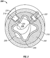
- the embodiment in Fig. 2 illustrates a four lobed stator 200.
- One embodiment of the profiled helical bore of a stator can have a relatively long pitch length (the axial distance of one 360-degree helical turn of one lobe), for example, a pitch length between two to twenty times that of the major diameter of the bore.
- Sleeve 108 is a resilient material (e.g., elastomer), and the outer tube 110 depicted in Fig. 1 is optional.
- the figures illustrate an even thickness sleeve and outer tube, although either or both can have variable thickness as is known in the art.
- the apex 112 of each lobe of the sleeve 108 can have has a lesser wall thickness than the thickness at each valley 114, or vice versa. See sleeve 308 in Fig. 3 for an example.
- Transducers (104A-104D) can be disposed in any location in cast material body 102.
- Transducer 104A which does not fall within the scope of the present invention as claimed is in communication with the profiled helical bore 106 and includes a port that extends through sleeve 108.
- Transducer 104A can be a piezo electric generator powered by the flow of fluid through the stator.
- transducer 104B includes a port that terminates adjacent sleeve 108.
- sleeve 108 is fluidicly permeable or formed of material that can transmit pressure thereacross (e.g., a highly resilient material)
- transducer 104B can read the pressure in bore 106.
- transducer 104B can detect any leakage of a fluid from sealed bore 106, e.g., if sleeve 108 becomes perforated.
- transducer 104C is fully encapsulated within cast material body 102.
- Transducer 104D which does not fall within the scope of the present invention as claimed is a reciprocating pump.
- reciprocating pump 104D includes an actuation member 116.
- actuation member 116 displaces a piston(s) or plunger(s) to facilitate pumping. Hydraulic power from reciprocating pump 104D can be used to power an actuator, for example.
- Fig. 2 is a schematic cross-sectional view of a stator 200 having a cast material body 202 with housings (218,222) disposed therein and a cavity 226 formed therein, according to an example that does not fall within the scope of the claimed invention.
- the embodiment in Fig. 2 includes a sleeve 208, which is a resilient material (e.g., elastomer), and an optional outer tube 210.
- a housing can be atmospherically sealed or pressure compensated, as is known in the art.
- a housing (218,222) can be any shape and is not limited to the rectangular forms depicted in Fig. 2 .
- the housing 218 can include a port 220 (shown with a dotted line) through the cast material body 202 into the profiled helical bore 206 and/or to an exterior surface of the cast material body 202 or stator 200.
- housing 222 is illustrated with ports through the cast material body 202 into the profiled helical bore 206 and/or to an exterior surface of the stator 200 (e.g., for a pressure compensated housing).
- Housing (218,222) can be formed from any material, for example, a polymer or metal.
- Transducer (not shown) can be disposed within a housing (218,222) before insertion of the housing (218,222) into the cast material body 202.
- a housing (218,222) is disposed into fluid cast material before the cast material is cured (e.g., solidified).
- an access panel 224 can be included in the outer tube 210 and/or profiled helical bore 206 (not shown).
- Access panel 224 can be any shape and can be attached to the stator 200 by any means, for example, weld, bolt, screw, adhesive, etc.
- housing 222 can include an access panel (not shown) to seal and/or to cover access port to housing 222 (or a void) from an exterior surface. It is appreciated that an access panel (not shown) could be utilized to seal and/or to cover an access port to housing 222 (or a cavity 226) from the profiled helical bore 206.
- stator 200 in Fig. 2 further depicts a cavity 226 in communication with and coterminous with the profiled helical bore in the cast material body 202.
- cavity 226 can extend through optional sleeve 108, e.g., coterminous with the profiled helical bore 206 in sleeve 108.
- Transducer can mount directly in cavity 226.
- Cavity 226 can be formed as a mirror image of at least part of a transducer, e.g., to removably receive a transducer. This can also serve to at least partially retain a transducer to the cast material body 202.
- Cavity 226 in cast material body 202 can include mounting hardware to attach a transducer.
- Mounting hardware can be disposed in fluidic cast material and the curing (e.g., solidifying) of the cast material can bond the mounting hardware to the cast material body 202.
- a portion of the mounting hardware would extend within the cast material body 202 to form a mechanical attachment to the cast material body 202.
- a cavity mold as is known the art, can be used to form a cavity 226. Cavity mold can be removed from the cast material body 202 or can remain attached to the cast material body 202, e.g., when stator 200 is in use as a progressive cavity apparatus.
- Cavity mold can be coated with a release agent or made of non-stick material, for example, polytetrafluoroethylene, to aid in the removal from cast material body (e.g., solidified cast material).
- a release agent for example, polytetrafluoroethylene
- cavity 226 can extend to the exterior surface of the cast material body 202 from the profiled helical bore 206.
- Fig. 3 is a schematic cross-sectional view of a stator 300 which does not form part of the invention as claimed, having a cast material body 302 and a transducer 304 disposed therein.
- Stator 300 does not include optional tube circumferential to the cast material body 302.
- Transducer 304 is disposed adjacent an exterior surface of the cast material body 302, which is the exterior surface of the stator 300.
- Transducer 304 is coterminous with exterior surface of the cast material body 302 in Fig. 3 .
- Stator 300 includes an internal sleeve 308.
- Stator 300 also includes a cavity 326. Cavity 326 can be formed as discussed above in reference to Fig. 2 .
- Optional access panel 324 can be included to seal and/or to cover opening of cavity 326 on exterior surface of the stator 300.
- Cast material body 302 can include a housing disposed therein.
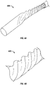
- Fig. 4A is a perspective view of a profiled helical tube 400, according to one embodiment of the invention.
- Profiled helical tube can be used as a sleeve, for example.
- Fig. 4B is a close-up perspective view of the profiled helical tube 400 of Fig. 4A more readily illustrating the lobes and valleys of the profiled helical form.
- Fig. 5 is a perspective view of a resilient material sleeve 508 (e.g., sleeve 400 from Figs.
- resilient shall refer to any material capable of substantially returning to an original shape or position, as after having been compressed, for example, an elastomer, rubber (e.g., nitrile or silicone,) propylene, fluorocarbon, urethane, or polyurethane.
- a resilient material can have a hardness of less than about 90 durometer or a hardness in the Shore A scale.
- the resilient material can be composed of a polymer having a glass transition temperature approximating the expected operating temperature of the progressive cavity motor to permit the polymer to retain its hardness until deployed in the well bore where such temperature would be found.
- the resiliency of the polymer above such temperature would be sufficient to permit the motor to operate efficiently, all as more fully described in US 2009/0169404 .
- Body 510 can, at least partially, provide mechanical support to a cast material body during use as a progressive cavity apparatus.
- the curing process can bond a cast material body (e.g., cast material layer) to body 510.
- a cast body can be formed on an exterior mold (not shown), then, after curing of cast material, bonded to body 510 to form stator, as shown in Fig. 3 .
- Body 510 can be a tube (e.g., 110 in Fig. 1 and 210 in Fig. 2 ), more specifically, a metal tube.
- a sleeve 508 with a profiled helical bore is provided.
- Sleeve 508 can retain a profiled helical form without external support or the curing of the fluidic cast material around the sleeve can retain the profiled helical form, as is describer further below via the use a support core 528 during curing and/or disposition of the sleeve 508 into the body 510 (e.g., mold).
- Tube 508 with a profiled helical bore can be formed by any means known in the art.
- the profiled helical inner surface is provided by the tube 508, and thus in this embodiment a profiled helical inner surface does not have to be preformed in the stator body and then lined with elastomer as is typical in the prior art.
- a resilient material sleeve 508 is formed by disposing a cylindrical semi-cured resilient material tube onto core 528, the core 528 preferably remains within the resilient material tube at least until the cast material is sufficiently cured to retain the profiled helical shape due to the resiliency of the semi-cured resilient material to a cylindrical, and thus a non-profiled helical, form.
- the core 528 would initially shape the sleeve 508. Furthermore, in forming an elastomeric layer by injection as in the prior art, the elastomeric layer is essentially the last component formed.
- the current invention allows the resilient material layer 508 to be one of the first components formed in the creation of a resilient material lined stator.
- the tube (e.g. sleeve) 508 is then disposed within a longitudinal bore of a body 510, depicted as a tube.
- Body 510 can be a simple cylindrical tube as shown in the figures, or any other shape or style of inner or outer diameter and is not limited to a tubular form.
- Body 510 can have a profiled helical inner and/or profiled helical outer surface or any type of complex inner geometry if so desired.
- the inner and outer diameter or profile of the longitudinal bore of the body 510 and the inner and outer diameter or profile of the sleeve 508 can independently be any size or shape provided the sleeve 508 can be disposed inside the body 510.
- fluidic cast material is then disposed in the void 534 formed between the outer surface of the sleeve 508, which is not required to be a profiled helical outer surface as shown, and the longitudinal bore of the body 510.
- cast material is in a fluid state when disposed in the void 534 and can be later cured with heat, pressure, the passage of time, etc.
- Cast material can conform to any shape exterior of the sleeve 508 to fill the entire void.
- Cast material can be any material suitable for use with a progressive cavity apparatus.
- Metal fillers or other heat conducting materials can be added if desired to conduct heat generated in the stator bore to the outer surface of the stator tube to aid in cooling.
- Cast material can be curable by thermosetting, for example. Multiple concentric layers of differing or similar cast materials can be utilized. The cast material can be selected based on the fluid, which can include other particulate matter, for example, drill bit cuttings, used to power or is pumped by a progressive cavity apparatus. Cast material can be selected based on any temperature exposure requirements, for example, the downhole fluid temperature.
- a bonding agent for example, a primer
- surface roughing or a bonding agent for example a primer
- At least one groove can be machined into the interior surface of the longitudinal bore of the body 510 to provide a mechanical lock between the body 510 and the cast material.
- the bore of the body 510 can be coated with a release agent or made of non-stick material, for example, polytetrafluoroethylene, to aid in the removal.
- a conduit, conductor, and/or pathway can be cast into the void between the body 510 and the sleeve 508 (e.g., in one embodiment, a resilient material tube).
- Conduit, conductor, and/or pathway in cast material body can connect to a transducer disposed in cast material body.
- Conduit, and/or conductor can be external to cast material body layer.
- Sleeve 508 can be an at least partially uncured material. At least partially uncured sleeve 508 can be cured concomitantly with the cast material.
- End ring 530 can be disposed at the proximal end of the longitudinal bore of the body 510 to center the sleeve 508 and/or core 528 within the longitudinal bore.
- sleeve 508 is design selected to retain a profiled helical form and/or resist deformation when cast material is disposed in void 534.
- a core 528 can be utilized without a sleeve 508.
- core 528 is displaced into the bore of body 510 and fluidic cast material is added to the void 534 between body 510 and core 528.
- the 528 core is removed, e.g., akin to threading a bolt out of a nut, to expose a profiled helical bore formed directly in the cast material.
- the profiled helical outer surface thereof can be coated with a release agent or made of non-stick material, for example, polytetrafluoroethylene.
- Core 528 can be a frangible or disposable material which can be broken, melted, chemically dissolved, etc. to remove from profiled helical bore imparted in cast material.
- a stator can be utilized as is or lined, e.g., by elastomer injection as is typical in the art. If desired, forming of a stator can include removing the body 510 from the cast material, e.g., stator 300 in Fig. 3 .
- Fig. 6 is a longitudinal cross-sectional view of a stator 600 according to an embodiment of the present invention, having a cast material body 602 with transducers 604A-604D disposed therein, according to one embodiment of the invention.
- Transducers 604A-604D can be distributed along an axial length of the stator 600 and/or circumferential to a longitudinal axis of a stator.
- Transducers 604A-604D can be distributed at a constant or variable interval along a stator.
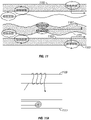
- Fig. 7 is a longitudinal cross-sectional view of a progressive cavity apparatus 700 having an electrical conducting section 702, according to one example that does not form part of the claimed invention.
- Progressive cavity apparatus 700 includes a rotor 704 with a profiled helical outer surface disposed in the profiled helical bore of a stator 706, with a sleeve 708 disposed therebetween.
- the sleeve 708 is a resilient material.
- the illustrated example depicts the sleeve 708 abutting the profiled helical bore of the stator 706.
- Sleeve 708 can abut the profiled helical bore of the stator 706.
- Sleeve 708 can abut the profiled helical outer surface of the rotor 704.
- Stator 706 can have a cast material body.
- electrical conducting section 702 includes an electrical conductor ring 710 in a cast material body of the stator 706, rotor 704 having an outer surface with a second electrical conductor ring 712 circumferential thereto, and an intermediate ring section 714 of the sleeve 708 comprising a conductive material therein to communicate between the first 710 and the second 712 electrical conductor rings.
- Sleeve 708 can be resilient material and include conductive material therein, for example, carbon. In one example, carbon particles are encapsulated within sleeve 708, which can be a non-conductive material.
- Electrical conductor ring 710 can be disposed into the cast material body of the stator 706 when the cast material is in a fluid state. Electrical conductor ring 710 can be circumferential to bore of the stator 706. Conductor or other transmittal means can provide power to and/or from each conductor ring (710,712).
- element 710 can be one of a magnet and a coil of a power generating apparatus and element 712 can be the other. Relative rotation therebetween can generate electricity. In this example, it can be desirable to ensure suitable resistivity characteristics of cast material.
- Progressive cavity apparatus 700 can include an intermediate ring section 714.
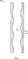
- Fig. 8 is a schematic longitudinal cross-sectional view of a stator 800 having a cast material body 802 and a transducer 804 disposed therein, according to an embodiment of the invention.
- Transducer 804 extends along an axial length of the bore 806.
- Transducer 804 can be a wire strain sensor or at least one optical fiber, for example.
- Transducer 804 can extend in a helical path along the bore 806.
- Transducers include both sensors and actuators.
- a sensor disposed within a cast material body can monitor or check the health of a stator. This can be done during stator use (e.g., use as a mud motor) or during a maintenance period.
- a stator having a cast material body with at least one transducer disposed therein can allow the following uses, for example.
- At least one transducer can be a temperature, pressure, strain, load, etc. sensor utilized during the formation of a stator.
- a signal from a temperature, pressure, strain, load etc. sensor of stator can be utilized to monitor the curing of the cast material. Monitoring can be in real time or a data log.
- heat is applied to the cast material to cure.
- Signal from a temperature sensor in the cast material can indicate the state of cure.
- a single sensor or multiple sensors can be utilized. Curing can be controlled via the signal. For example, regulating the heat applied to the cast material to generate a desired temperature (or temperature distribution) in the cast material and/or regulating the pressure applied to the cast material to generate a desired pressure (or pressure distribution) in the cast material.
- a sensor in the cast material can be utilized to detect any discontinuity in the stator.
- a stator can be heated to a desired temperature and a signal returned from at least one temperature sensor in the cast material. Signal can be compared to temperature signals from other temperature sensors disposed in the cast material or a prototypic signal.
- a prototypic signal can be the signal expected when no discontinuity is present. For example, one can monitor the heat transfer through the cast material via temperature sensor(s) and this can be compared to a known model, i.e., any imperfections or voids will disrupt the measurements.
- a sensor in the cast material can be utilized to cast or assemble a stator and/or to monitor or assemble a rotor and a stator to form a progressive cavity apparatus.
- a strain, pressure, load, and/or temperature signal can be provided from respective sensor(s) disposed in the cast material body. Strain, pressure, load, and/or temperature signal provided during the insertion of a rotor into the profiled helical bore of a stator can be compared to a prototypic signal to determine any undesirable fit therebetween.
- strain, pressure, load, and/or temperature signal provided during the rotation of a rotor into the profiled helical bore of a stator can be compared to a prototypic signal to determine any deviation therebetween.
- Deviation of signal and a prototypic signal can correspond to an undesirable fit due to wear, improper parts, etc. and/or correspond to any damage to the progressive cavity apparatus, e.g., damage to a resilient material sleeve between a rotor and stator.
- a prototypic signal can be a first signal, which can then be compared to a subsequent second signal to ascertain any deviation therebetween.
- the previous methods can be used in a positive interference fit stator, as is known in the art, e.g., the resilient material sleeve is at least partially compressed during rotation of the rotor within the profiled helical bore of the stator.
- a plurality of pressure sensors distributed along, and in communication with, a profiled helical bore.
- the pressure sensors are distributed along a single pitch length, e.g., along a helical path traced by one lobe, as shown schematically with reference characters 904A- 904C in Fig. 9 .
- Pressure sensor would be used to check the pressure integrity of a cavity within the assembled motor.
- a cavity is a void between the rotor and stator. There is a closed cavity at each pitch distance and this cavity (i.e., void) travels along the progressive cavity apparatus to effectively carry a slug of fluid.
- Stator can have one sensor every pitch distance, for example, pressure sensors to provide the pressure distribution along the progressive cavity apparatus, i.e., to check the leakage and/or fit between rotor and stator.
- pressure, load, torsion, etc., sensors can be used to check fit and/or performance both during manufacture and operation as a progressive cavity apparatus (e.g., down hole).
- a signal corresponding to the pressure, load, and/or torsion along the stator can allow an assessment of power output as a progressive cavity motor, for example.
- a cavity is the space between the rotor and stator and there is a closed cavity at each pitch distance. This cavity/void travels along the profiled helical bore of a stator, effectively carrying a slug of fluid, but the sensors are fixed in the stator.
- pressure measurements from sensors e.g., 904A-904C
- a strain gauge e.g., 804 in Fig. 8
- a strain gauge 804 in Fig. 8 can measure the reactive torque on the stator 800 from a pressurized cavity.
- any pressure sensors e.g., sensors 904A-904C in Fig. 9
- the cause of a leak between cavities could be wear or damage to either the stator (e.g., the resilient material liner) or rotor.
- This information can be combined with a flow rate into the stator 800 and the rate of revolution (e.g., RPM) between the rotor and stator (e.g., detected from periodic sensor readings) to determine power efficiency.
- a prototypic signal of a sensor can be provided.
- stator bore 106 can be pressurized to a chosen pressure and the signal from the sensor(s) at the chosen pressure can be the prototypic pressure signal.
- stator bore 106 can be heated to a chosen temperature and the signal from the sensor(s) at the chosen temperature can be the prototypic temperature signal.
- An actual pressure and/or temperature of the stator 100 from the sensor(s) (e.g., 104A-104C) when exposed to the chosen pressure and/or temperature, respectively, can be compared to the prototypic signals. Any deviation therebetween can indicate a discontinuity of the stator 100, e.g., discontinuity of the cast material 102 and/or resilient material 108.
- a plurality of sensors can be distributed along the stator, e.g., sensors 904A-904C depicted schematically in Fig. 9 .
- a signal from a first sensor can be compared to a signal from another sensor(s) to determine any deviation therebetween. Deviation can indicate failure of the stator (e.g., a crack therein, resilient material layer/seal failure detection, wear of rotor/stator) and/or presence of a slug of fluid in the embodiment of a pressure sensor. Comparing concurrent signals can allow monitoring along a desired length of a stator. For example is pressure and/or strain sensors are embedded in the cast material layer, the signal(s) therefrom can be utilized to indicate the torque and/or power characteristic of the motor as described herein.
- a method of assembling a rotor and a stator of a progressive cavity apparatus can include providing a prototypic signal generated when a rotor is inserted correctly (e.g., proper tolerances) into the profiled helical bore of a stator.
- Prototypic sensor signal can be for a pressure, strain, temperature signal, etc.
- An actual signal from a sensor during and/or after assembly can be compares to a prototypic signal, with a variance corresponding to undesirable fit.
- a pressure, strain, temperature sensor, etc. can be utilized to monitor a progressive cavity apparatus or a stator thereof.
- a prototypic signal of a sensor e.g., 104A-104C
- the condition of the stator 100 can be ascertained via the sensor(s). For example, a first signal from a sensor can be compared to a second subsequent signal from a sensor, and any change can indicate an undesired fit and/or failure of the stator.
- the degree of change corresponding to an undesired fit and/or failure of the stator can be determined, i.e., relatively small deviations in signals are not necessarily indicative of undesired fit and/or failure of the stator.
- These examples can be used to create a real time monitoring system.
- OST Outgoing Service Test
- sensor(s) of the new progressive cavity apparatus e.g., mud motor
- the heat generated can be an indication of an impending fault, e.g., as an engine monitor.
- the power output of a progressive cavity apparatus also gives rise to heat generation, i.e., a characteristic finger print. This temperature profile can be ascertained and later compared to a signal from a temperature sensor(s) to determine any fault and/or to approximate the power output of the progressive cavity apparatus.
- Stator load can correspond to the weight on bit when the progressive cavity apparatus is a mud motor attached to a drill bit.
- Sensor can be an accelerometer, shock sensor, magnetometer, etc. to measure the motion of the stator and/or rotor for drilling mechanics and bottom hole assembly (BHA) motion monitoring.
- BHA bottom hole assembly
- Formation sensors, sonic sensors, etc. can be disposed into the cast material, e.g., sensor 304 in Fig. 3 . These can be used for resistivity, seismic evaluation, or other logging measurements. Embedded sensor technology in a stator can be used for measurement and/or logging while drilling.
- Electromagnetic induction coils can be disposed in cast material (e.g., 804 in Fig. 8 ) to transmit information (active or passively) across the stator.
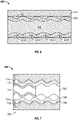
- electromagnetic coils can be disposed in the elastomeric cast materials 1101, in the interior surface of the stator tub body 1103, or on the exterior surface of the stator body 1105. These coils can be cooperatively mounted to communicate with coils mounted on a rotor of the progressive cavity motor 1107 as needed for sensing.
- Field lines drawn are illustrative only and not intended to limit the scope or direction of the electromagnetic field, generated or sensed by any of these coils. As more fully shown in Fig.
- the coils can be circumferential to the longitudinal axis of the stator body 1109 or mounted in a tangential plane to the longitudinal axis of the stator body 1111, whether mounted on an interior surface of the stator or an exterior surface of the stator for the purposes required. Any number of these types of coils may be combined in one stator body to accomplish a number of useful sensing and control functions, all in a manner well known to those in this art.
- the usefulness of the progressive cavity pump is expanded by using the stator body itself as a support for the electromagnetic coils used by these sensors.
- Load sensors can be disposed in cast material to detect torque and/or weight on bit.
- wire strain sensor e.g., 804 in Fig. 8
- the small changes in resistivity of the wire strain sensor can be ascertained.
- These changes in resistivity can be compared to a prototypic change in resistivity to indicate an axial deflection (e.g., weight on bit) and/or a radial deflection (e.g., torque)
- Changes in resistance can also be used to detect overall temperature changes along the motor.
- Optical fiber can be disposed in cast material (e.g., 804 in Fig. 8 ). Light can be transmitted through the optical fiber. Backscatter of light can indicate a deflection of optical fiber, and thus a strain or deflection of the cast material in which the optical fiber is disposed. This deflection can indicate an axial deflection (e.g., weight on bit) and/or a radial deflection (e.g., torque).
- the high noiseless bandwidth associated with the disposition of optical fiber in the cast material can be permit miniature cameras to examine pump internals as well as well conditions in real time in both the visible and infrared spectrum. Although available in wired systems, the electronic noise associated with such technology makes optical viewing difficult.
- Fig. 10 is a cutaway perspective view of a stator 1000 that does not fall within the scope of the invention as claimed having sleeve 1008 with transducers 1010 disposed therein, according to one embodiment of the invention.
- sleeve 1008 is a resilient material.
- Stator 1000 includes cast material body 102, which can be surrounded by a body (not shown) as discussed above.
- Profiled helical bore 1006 extends through sleeve 1008. Portion of cast material body 1002 is shown removed for illustrative purposes. Cast material body can optionally include a transducer 1004 disposed therein.
- Transducer 1010 can be encapsulated within the sleeve 1008 (as shown) or disposed partially therein sleeve 1008. Sensors, electronics and/or wires can be disposed (or encapsulated) into a resilient material sleeve, like a deformable or flexible circuit board, during its manufacture. Sensors 1010 disposed in the sleeve 1008 can allow for monitoring of the continuity and/or thickness remotely.
- Sensor 1010 is illustrated as a mesh. Any discontinuity in the mesh 1010 can indicate a crack or other defect in the sleeve 1008 (e.g., resilient material layer). Wire(s) 1012 can extend from sleeve 1008 into and/or through the cast material 1002. Sleeve 1008 can be cured before, during, and/or after curing of cast material. In one embodiment, at least the inner surface of the sleeve 1008 is resilient.
- Forming a resilient material sleeve 1008 can include providing a sleeve mold, filling the sleeve mold with a resilient material in a fluid state, disposing at least one transducer at least partially into the resilient material, and curing the resilient material to form the resilient material sleeve with at least one transducer disposed therein.
- Sleeve mold can form a tubular sleeve or a profiled helical sleeve, thus permitting embedded electronics based on flexible circuit board technology to be implemented within this flexible member. This could enable this sleeve to monitor and record operational details of the progressive cavity pump and either transmit or save such data for subsequent download and examination.
Description
- The invention relates generally to stators for use with progressive cavity pumps or motors; more specifically, to a stator having at least one transducer therein and methods of forming and using the stator.
- Progressive cavity pumps or motors, also referred to as a progressing cavity pumps or motors, typically include a power section consisting of a rotor with a profiled helical outer surface disposed within a stator with a profiled helical bore. The rotor and stator of a progressive cavity apparatus operate according to the Moineau principle, originally disclosed in
U.S. Pat. No. 1,892,217 . - In use as a pump, relative rotation is provided between the stator and rotor by any means known in the art, and a portion of the profiled helical outer surface of the rotor engages the profiled helical bore of the stator to form a sealed chamber or cavity. As the rotor turns eccentrically within the stator, the cavity progresses axially to move any fluid present in the cavity.
- In use as a motor, a fluid source is provided to the cavities formed between the rotor and stator. The pressure of the fluid causes the cavity to progress and imparts relative rotation between the stator and rotor. In this manner fluidic energy can be converted into mechanical energy.
- As progressive cavity pumps or motors rely on a seal between the stator and rotor surfaces, one of or both of these surfaces can include a resilient or dimensionally forgiving material. Typically, the resilient material has been a relatively thin layer of elastomer disposed in the interior surface of the stator. A stator with a thin elastomeric layer is typically referred to as thin wall or even wall design.
- An elastomeric lined stator with a uniform or even thickness elastomeric layer has previously been disclosed in
U.S. Pat. No. 3,084,631 on "Helical Gear Pump with Stator Compression". The prior art has evolved around the principle of injecting an elastomer into a relatively narrow void between a stator body with a profiled helical bore and a core (e.g., mandrel) with a profiled helical outer surface. The core is then removed after curing of the elastomer and the remaining assembly forms an elastomeric lined stator. The elastomer layer is essentially the last component formed. - The stator bodies mentioned above have a pre-formed profiled helical bore. The profiled helical bore is generally manufactured by methods such as rolling, swaging, or spray forming, as described in
U.S. Pat. No. 6,543,132 on "Methods of Making Mud Motors". Similarly, a profiled helical bore can be formed by metal extrusion, as described inU.S. Pat. No. 6,568,076 on "Internally Profiled Stator Tube". Further, various hot or cold metal forming techniques, such as pilgering, flow forming, or hydraulic forming, as described in P. C. T.Pub. No. WO 2004/036043 A1 on "Stators of a Moineau-Pump", can be used to form a stator body with a profiled helical bore. - A stator body can also be formed by creating a profiled helical bore in relatively thin metal tubing. This formed metal tube can then be used as the stator body by itself, with an injected inner elastomeric layer, or the formed metal tube can be inserted inside into a second body with a longitudinal bore to form the stator body. A stator body with a profiled helical bore can also be formed through other process such as sintering or hot isostatic pressing of powdered materials, for example, a metal, or the profiled helical bore can be machined directly into a body.
- It is also desirable to include transducers, including sensors and actuators, in the stator body. The current methods of producing the stator body require complicated machining, etc. of the stator body material, which is typically steel, and therefore are not conducive to providing additional machining for inclusion of the transducers on the finished product. As will be more fully discussed herein, the inclusion of transducers can also aid in the fabrication of stators in a number of ways.
- Referring to the particular embodiment of a progressive cavity downhole motor used in drilling operations (e.g., mud motor), the space available for sensing and measuring devices of downhole conditions is limited. The operational portion of a typical bottom hole assembly, including the motors can be relatively long, up to about 9 meters (30 feet) or more. By utilizing the stator of the progressive cavity motor, which heretofore has not contained any sensing or measuring devices, as a carrier of electronics such as transducers then valuable additional space may be claimed for more sophisticated drilling bottom hole assemblies.
- Motors are preferably installed as proximal to the drill bit as possible; yet space adjacent the bit is particularly valuable because of its proximity to the newly drilled formation. Transducers, such as a sensor, measuring relevant down hole data as close to the newly drilled formation as possible allows better and more timely well placement decisions to be made, i.e., to control the direction of drilling.
- Further, motors undergo significant stress and strain, particularly the load paths through the resilient material layer (e.g., the seal) as it effectively reacts to the bit torque and any forces from downhole transmissions and bearings. For example, some motors can deliver hundreds of kilowatts of power for 200 hours or more at elevated temperatures of about 1500 C (3000 F) or more.
- Monitoring the status of the stator and/or the formation and new borehole, such as the temperature, strain and pressure, can allow an assessment of current performance capabilities, e.g., how much power can be generated before the motor might fail, how long is the motor expected to last, and other questions of similar importance to expensive drilling programs.
- The disposition of conduits, conductors, and/or pathways which can be used for communicating in electrical, hydraulic and/or mechanical form was previously disclosed in the prior art and are well known to those in this art. See for example
U.S. 2008/0025859 . -
EP 1739307 describes a progressive cavity pump having a rotationally driven rotor mounted in a stator, whereby the stator consists at least in areas of an elastic material. At least one sensor is provided for the stator by which compressions and/or movements of the stator or elastic material are measured in the course of the rotation of the rotor. The sensor may be a pressure transducer, force transducer and/or displacement transducer. The measurement sensor may be integrated at least in part in the elastic material of the stator.US 5679894 describes a mud motor for use in drilling a borehole, comprising a stator having a helically contoured inner surface, a rotor having a helically contoured outer surface rotatably disposed in the stator to rotate along a common axis of the stator and motor, and a plurality of sensors within the mud motor for determining various parameters of the motor. - The present invention resides in a method of forming a stator with a profiled helical bore as defined in claim 1 and in a stator as defined in claim 8. Preferred embodiments are defined in the dependent claims.
-
-
Fig. 1 is a schematic cross-sectional view of a stator having a cast material body and transducers disposed therein, according to one embodiment of the invention. Some of the illustrated transducers do not fall within the scope of the invention as claimed -
Fig. 2 is a schematic cross-sectional view of a stator having a cast material body with housings disposed therein and a cavity formed therein, according to one example that does not form part of the present invention. -
Fig. 3 is a schematic cross-sectional view of a stator having a cast material body and a transducer disposed therein, according to an example that does not form part of the present invention. -
Fig. 4A is a perspective view of a profiled helical tube. -
Fig. 4B is a close-up perspective view of the profiled helical tube ofFig. 4A . -
Fig. 5 is a perspective view of a resilient material sleeve disposed on a core with a profiled helical outer surface and within a longitudinal bore of a body to form a resilient material lined stator, according to one embodiment of the invention. -
Fig. 6 is a longitudinal cross-sectional view of a stator having a cast material body with transducers disposed therein, according to one embodiment of the invention. -
Fig. 7 is a longitudinal cross-sectional view of a progressive cavity apparatus electrical having a conducting section, according to an example that does not form part of the present invention. -
Fig. 8 is a schematic longitudinal cross-sectional view of a stator having a cast material body and a transducer disposed therein, according to one embodiment of the invention. -
Fig. 9 is cutaway perspective view of a stator having a cast material body with transducers disposed therein, according to an example that does not form part of the claimed e invention. -
Fig. 10 is a cutaway perspective view of a stator having a sleeve with transducers disposed therein, according to an example that does not form part of the claimed invention. -
Fig. 11 is a schematic view of the mounting of electromagnetic coils at various locations in either a stator or a rotor in an example that does not form part of the present invention. -
Fig. 11A is a schematic view of the two alternative mounting techniques which may be employed to mount electromagnetic coils on either a rotor or a stator in another example that does not form part of the present invention. -
Fig. 1 is a schematic cross-sectional view of astator 100 having acast material body 102 andtransducers 104A-104D disposed therein. Thestator including transducers transducers - As used herein, the term cast material shall refer to a material poured into a mold in a molten or fluid state. Uncured cast material can be at a fluid state at about ambient atmospheric temperature and/or pressure, e.g., 210 C (700 F) and 101 kPa (14.7 psi), respectively.
- Cast material can be any material suitable for use with a progressive cavity apparatus. For example, the cast material can be a resin or mixture of resins. One non-limiting example of a resin is the High Temperature Mould Maker (C-1) liquid epoxy by Devcon U.K., which is rated for use up to 260°C (500°F). Cast material can be a metal filled, ceramic filled, and/or polymeric fiber filled epoxy, e.g., those materials can be used as a matrix encapsulated in the cast material. Non-limiting examples of metal filled epoxies are those commonly known as liquid metal and are produced by ITW Devcon in the United States and Freeman Mfg. & Supply Co. in the United Kingdom, for example. Metal fillers which can be utilized are steel, aluminum, and/or titanium. One non-limiting example of a polymeric fiber filled resin is a polycarbon fiber ceramic filled NovolacTM resin by Protech Centreform (U.K.) Ltd. that remains stable up to 240°C (460°F). Metal fillers or other heat conducting materials can be added if desired for strength and/or to conduct heat generated in the stator bore to the outer surface of the stator tube to aid in cooling.
- Another type of cast material is an amorphous alloy, which is an alloy having an amorphous atomic structure (i.e., not crystalline). Amorphous alloys retain the amorphous structure after repeated re-heating.
- Cast material can be cured by the passage of time and/or thermosetting, for example. Multiple concentric layers of differing or similar cast materials can be utilized. Cast material can be selected to resist premature wear based on the fluid, which can include other particulate matter, such as the drill bit mud, used to power or be pumped through a progressive cavity apparatus. Cast material can also be selected based on expected temperature exposure requirements, for example, the downhole temperature.
- In one embodiment, the cast material is molded into a desired shape, and the molding process allows a transducer to be disposed (e.g., embedded) within the cast material. More particularly, the fluidic nature of the material while the stator body is being cast allows the material to conform to whatever is disposed in the mold. This can allow the direct insertion of a transducer, housing, cavity mold, or other apparatus into the fluidic cast material, which can then be cured (e.g., solidified) into a cast material body.
- Note the embodiments depicted in the drawings are not necessarily to scale. The term transducer shall refer to a device which can transform energy from one type to another, even if both energy types are in the same energy domain, e.g., mechanical, chemical or electrical. A transducer can include devices which couple energy types within a domain, e.g., an electromagnetic communication apparatus. One example of an electromagnetic communication apparatus that does not form part of the present invention as claimed is described below in reference to
Fig. 7 . A transducer can be a sensor and/or an actuator. A sensor typically monitors a system and an actuator typically imposes a condition on a system. A transducer can include, but is not limited to, a pressure sensor, an electrode, a strain sensor, a temperature sensor, a coil of a power generating apparatus, a magnet of a power generating apparatus, a piezo electric generator (which can be in communication with a profiled helical bore of a stator), a reciprocating pump, an accelerometer, a shock sensor, a magnetometer, an inclinometer, a formation sensor, a resistivity sensor, a seismometer, an electromagnetic induction coil, an electromagnetic communication apparatus, a load sensor, a wire strain sensor, an optical fiber, a magnetorheological sensor, or any combination thereof. According to embodiments of the invention, a transducer is embedded entirely within the cast material body or is entirely contained within the cast material body with an exposed port on an end surface thereof terminating adjacent a sleeve. A transducer can be wireless, as is known in the art. An antenna can be disposed within the cast material body. Battery or other power storing and/or generating device can be disposed on, or encapsulated within, the cast material. - In the embodiment of
Fig. 1 ,stator 100 has acast material body 102 including a plurality of transducers (104A-104B) disposed therein.Stator 100 has a profiledhelical bore 106 extending axially therethrough. The profiled helical form of thebore 106 can be seen more readily inFigs. 2 and6 .Fig. 1 illustrates a five lobed profile, however a stator operating according to the Moineau principle can have as few as two lobes. For example, the embodiment inFig. 2 illustrates a fourlobed stator 200. One embodiment of the profiled helical bore of a stator can have a relatively long pitch length (the axial distance of one 360-degree helical turn of one lobe), for example, a pitch length between two to twenty times that of the major diameter of the bore. -
Sleeve 108, is a resilient material (e.g., elastomer), and theouter tube 110 depicted inFig. 1 is optional. The figures illustrate an even thickness sleeve and outer tube, although either or both can have variable thickness as is known in the art. For example, theapex 112 of each lobe of thesleeve 108 can have has a lesser wall thickness than the thickness at eachvalley 114, or vice versa. Seesleeve 308 inFig. 3 for an example. - Transducers (104A-104D) can be disposed in any location in
cast material body 102.Transducer 104A which does not fall within the scope of the present invention as claimed is in communication with the profiledhelical bore 106 and includes a port that extends throughsleeve 108.Transducer 104A can be a piezo electric generator powered by the flow of fluid through the stator. According to an embodiment of the present invention,transducer 104B includes a port that terminatesadjacent sleeve 108. In an embodiment wheresleeve 108 is fluidicly permeable or formed of material that can transmit pressure thereacross (e.g., a highly resilient material),transducer 104B can read the pressure inbore 106. Ifsleeve 108 is not permeable or formed of material that cannot transmit pressure thereacross,transducer 104B can detect any leakage of a fluid from sealedbore 106, e.g., ifsleeve 108 becomes perforated. According to an embodiment of the invention,transducer 104C is fully encapsulated withincast material body 102.Transducer 104D which does not fall within the scope of the present invention as claimed is a reciprocating pump. In the illustrated example, reciprocatingpump 104D includes anactuation member 116. In use, the outer surface of a rotor (not shown) rotating within the profiledhelical bore 106 would periodically contactactuation member 116, which displaces a piston(s) or plunger(s) to facilitate pumping. Hydraulic power from reciprocatingpump 104D can be used to power an actuator, for example. -
Fig. 2 is a schematic cross-sectional view of astator 200 having acast material body 202 with housings (218,222) disposed therein and acavity 226 formed therein, according to an example that does not fall within the scope of the claimed invention. The embodiment inFig. 2 includes asleeve 208, which is a resilient material (e.g., elastomer), and an optionalouter tube 210. A housing can be atmospherically sealed or pressure compensated, as is known in the art. A housing (218,222) can be any shape and is not limited to the rectangular forms depicted inFig. 2 . In an example that does not form part of the invention as claimed, thehousing 218 can include a port 220 (shown with a dotted line) through thecast material body 202 into the profiled helical bore 206 and/or to an exterior surface of thecast material body 202 orstator 200. In this example,housing 222 is illustrated with ports through thecast material body 202 into the profiled helical bore 206 and/or to an exterior surface of the stator 200 (e.g., for a pressure compensated housing). Housing (218,222) can be formed from any material, for example, a polymer or metal. Transducer (not shown) can be disposed within a housing (218,222) before insertion of the housing (218,222) into thecast material body 202. In this example, a housing (218,222) is disposed into fluid cast material before the cast material is cured (e.g., solidified). If access to a housing (218,222) and/or transducer is desired, anaccess panel 224 can be included in theouter tube 210 and/or profiled helical bore 206 (not shown).Access panel 224 can be any shape and can be attached to thestator 200 by any means, for example, weld, bolt, screw, adhesive, etc. In an embodiment without anouter tube 210,housing 222 can include an access panel (not shown) to seal and/or to cover access port to housing 222 (or a void) from an exterior surface. It is appreciated that an access panel (not shown) could be utilized to seal and/or to cover an access port to housing 222 (or a cavity 226) from the profiled helical bore 206. - In this example which does not form part of the invention as claimed,
stator 200 inFig. 2 further depicts acavity 226 in communication with and coterminous with the profiled helical bore in thecast material body 202. Similarly,cavity 226 can extend throughoptional sleeve 108, e.g., coterminous with the profiled helical bore 206 insleeve 108. Transducer can mount directly incavity 226.Cavity 226 can be formed as a mirror image of at least part of a transducer, e.g., to removably receive a transducer. This can also serve to at least partially retain a transducer to thecast material body 202.Cavity 226 incast material body 202 can include mounting hardware to attach a transducer. Mounting hardware can be disposed in fluidic cast material and the curing (e.g., solidifying) of the cast material can bond the mounting hardware to thecast material body 202. For example, a portion of the mounting hardware would extend within thecast material body 202 to form a mechanical attachment to thecast material body 202. A cavity mold, as is known the art, can be used to form acavity 226. Cavity mold can be removed from thecast material body 202 or can remain attached to thecast material body 202, e.g., whenstator 200 is in use as a progressive cavity apparatus. Cavity mold can be coated with a release agent or made of non-stick material, for example, polytetrafluoroethylene, to aid in the removal from cast material body (e.g., solidified cast material). Although not shown,cavity 226 can extend to the exterior surface of thecast material body 202 from the profiled helical bore 206. -
Fig. 3 is a schematic cross-sectional view of astator 300 which does not form part of the invention as claimed, having acast material body 302 and atransducer 304 disposed therein.Stator 300 does not include optional tube circumferential to thecast material body 302.Transducer 304 is disposed adjacent an exterior surface of thecast material body 302, which is the exterior surface of thestator 300.Transducer 304 is coterminous with exterior surface of thecast material body 302 inFig. 3 .Stator 300 includes aninternal sleeve 308.Stator 300 also includes acavity 326.Cavity 326 can be formed as discussed above in reference toFig. 2 .Optional access panel 324 can be included to seal and/or to cover opening ofcavity 326 on exterior surface of thestator 300.Cast material body 302 can include a housing disposed therein. - Referring now to
Figs. 4A-5 , one method of forming a stator is described.Fig. 4A is a perspective view of a profiledhelical tube 400, according to one embodiment of the invention. Profiled helical tube can be used as a sleeve, for example.Fig. 4B is a close-up perspective view of the profiledhelical tube 400 ofFig. 4A more readily illustrating the lobes and valleys of the profiled helical form.Fig. 5 is a perspective view of a resilient material sleeve 508 (e.g.,sleeve 400 fromFigs. 4A-4B ) disposed on a core with a profiled helical outer surface and within a longitudinal bore of abody 510 to form a resilient material linedstator 500, according to one embodiment of the invention. As used herein, the term resilient shall refer to any material capable of substantially returning to an original shape or position, as after having been compressed, for example, an elastomer, rubber (e.g., nitrile or silicone,) propylene, fluorocarbon, urethane, or polyurethane. A resilient material can have a hardness of less than about 90 durometer or a hardness in the Shore A scale. Alternatively, the resilient material can be composed of a polymer having a glass transition temperature approximating the expected operating temperature of the progressive cavity motor to permit the polymer to retain its hardness until deployed in the well bore where such temperature would be found. The resiliency of the polymer above such temperature would be sufficient to permit the motor to operate efficiently, all as more fully described inUS 2009/0169404 . -
Body 510 can, at least partially, provide mechanical support to a cast material body during use as a progressive cavity apparatus. The curing process can bond a cast material body (e.g., cast material layer) tobody 510. Alternatively, a cast body can be formed on an exterior mold (not shown), then, after curing of cast material, bonded tobody 510 to form stator, as shown inFig. 3 .Body 510 can be a tube (e.g., 110 inFig. 1 and 210 inFig. 2 ), more specifically, a metal tube. - In an embodiment of the present invention, for making a stator, a
sleeve 508 with a profiled helical bore is provided.Sleeve 508 can retain a profiled helical form without external support or the curing of the fluidic cast material around the sleeve can retain the profiled helical form, as is describer further below via the use asupport core 528 during curing and/or disposition of thesleeve 508 into the body 510 (e.g., mold). -
Tube 508 with a profiled helical bore can be formed by any means known in the art. The profiled helical inner surface is provided by thetube 508, and thus in this embodiment a profiled helical inner surface does not have to be preformed in the stator body and then lined with elastomer as is typical in the prior art. Aresilient material sleeve 508 is formed by disposing a cylindrical semi-cured resilient material tube ontocore 528, thecore 528 preferably remains within the resilient material tube at least until the cast material is sufficiently cured to retain the profiled helical shape due to the resiliency of the semi-cured resilient material to a cylindrical, and thus a non-profiled helical, form. More succinctly, thecore 528 would initially shape thesleeve 508. Furthermore, in forming an elastomeric layer by injection as in the prior art, the elastomeric layer is essentially the last component formed. The current invention allows theresilient material layer 508 to be one of the first components formed in the creation of a resilient material lined stator. - After formation, the tube (e.g. sleeve) 508 is then disposed within a longitudinal bore of a
body 510, depicted as a tube.Body 510 can be a simple cylindrical tube as shown in the figures, or any other shape or style of inner or outer diameter and is not limited to a tubular form.Body 510 can have a profiled helical inner and/or profiled helical outer surface or any type of complex inner geometry if so desired. The inner and outer diameter or profile of the longitudinal bore of thebody 510 and the inner and outer diameter or profile of thesleeve 508 can independently be any size or shape provided thesleeve 508 can be disposed inside thebody 510. - When the
body 510 and thesleeve 508 are in a desired position in this embodiment, fluidic cast material is then disposed in the void 534 formed between the outer surface of thesleeve 508, which is not required to be a profiled helical outer surface as shown, and the longitudinal bore of thebody 510. In one embodiment, cast material is in a fluid state when disposed in thevoid 534 and can be later cured with heat, pressure, the passage of time, etc. To keep the fluidic or otherwise non-fully cured cast material within the longitudinal bore of thebody 510, one can seal at least a distal end of the void 534 between the outer surface of thesleeve 508 and the longitudinal bore of thebody 510. - Cast material can conform to any shape exterior of the
sleeve 508 to fill the entire void. Cast material can be any material suitable for use with a progressive cavity apparatus. Metal fillers or other heat conducting materials can be added if desired to conduct heat generated in the stator bore to the outer surface of the stator tube to aid in cooling. - Cast material can be curable by thermosetting, for example. Multiple concentric layers of differing or similar cast materials can be utilized. The cast material can be selected based on the fluid, which can include other particulate matter, for example, drill bit cuttings, used to power or is pumped by a progressive cavity apparatus. Cast material can be selected based on any temperature exposure requirements, for example, the downhole fluid temperature.
- If further adhesion between the
sleeve 508 and cast material is desired, a bonding agent, for example, a primer, can be applied to the exterior surface of thesleeve 508 prior to insertion into the longitudinal bore of thebody 510. If further adhesion between thebody 510 and the cast material is desired, surface roughing or a bonding agent, for example a primer, can be applied to the interior surface of thebody 510 prior to the insertion therein of thesleeve 508. At least one groove (not shown) can be machined into the interior surface of the longitudinal bore of thebody 510 to provide a mechanical lock between thebody 510 and the cast material. If removal of thebody 510 is desired, the bore of thebody 510 can be coated with a release agent or made of non-stick material, for example, polytetrafluoroethylene, to aid in the removal. - As discussed in the prior art and especially
U.S. 2008/002589 a conduit, conductor, and/or pathway can be cast into the void between thebody 510 and the sleeve 508 (e.g., in one embodiment, a resilient material tube). Conduit, conductor, and/or pathway in cast material body can connect to a transducer disposed in cast material body. Conduit, and/or conductor can be external to cast material body layer.Sleeve 508 can be an at least partially uncured material. At least partiallyuncured sleeve 508 can be cured concomitantly with the cast material.End ring 530 can be disposed at the proximal end of the longitudinal bore of thebody 510 to center thesleeve 508 and/orcore 528 within the longitudinal bore. - In another embodiment,
sleeve 508 is design selected to retain a profiled helical form and/or resist deformation when cast material is disposed invoid 534. - It is also appreciated that in an example that does not form part of the present invention, a
core 528 can be utilized without asleeve 508. In one embodiment,core 528 is displaced into the bore ofbody 510 and fluidic cast material is added to the void 534 betweenbody 510 andcore 528. When cast material is sufficiently cured, the 528 core is removed, e.g., akin to threading a bolt out of a nut, to expose a profiled helical bore formed directly in the cast material. If removal of thecore 528 is desired, the profiled helical outer surface thereof can be coated with a release agent or made of non-stick material, for example, polytetrafluoroethylene.Core 528 can be a frangible or disposable material which can be broken, melted, chemically dissolved, etc. to remove from profiled helical bore imparted in cast material. Such a stator can be utilized as is or lined, e.g., by elastomer injection as is typical in the art. If desired, forming of a stator can include removing thebody 510 from the cast material, e.g.,stator 300 inFig. 3 . -
Fig. 6 is a longitudinal cross-sectional view of astator 600 according to an embodiment of the present invention, having acast material body 602 withtransducers 604A-604D disposed therein, according to one embodiment of the invention.Transducers 604A-604D can be distributed along an axial length of thestator 600 and/or circumferential to a longitudinal axis of a stator.Transducers 604A-604D can be distributed at a constant or variable interval along a stator. -
Fig. 7 is a longitudinal cross-sectional view of aprogressive cavity apparatus 700 having anelectrical conducting section 702, according to one example that does not form part of the claimed invention.Progressive cavity apparatus 700 includes arotor 704 with a profiled helical outer surface disposed in the profiled helical bore of astator 706, with asleeve 708 disposed therebetween. In one embodiment, thesleeve 708 is a resilient material. The illustrated example depicts thesleeve 708 abutting the profiled helical bore of thestator 706.Sleeve 708 can abut the profiled helical bore of thestator 706.Sleeve 708 can abut the profiled helical outer surface of therotor 704.Stator 706 can have a cast material body. - In one example,
electrical conducting section 702 includes anelectrical conductor ring 710 in a cast material body of thestator 706,rotor 704 having an outer surface with a secondelectrical conductor ring 712 circumferential thereto, and anintermediate ring section 714 of thesleeve 708 comprising a conductive material therein to communicate between the first 710 and the second 712 electrical conductor rings.Sleeve 708 can be resilient material and include conductive material therein, for example, carbon. In one example, carbon particles are encapsulated withinsleeve 708, which can be a non-conductive material.Electrical conductor ring 710 can be disposed into the cast material body of thestator 706 when the cast material is in a fluid state.Electrical conductor ring 710 can be circumferential to bore of thestator 706. Conductor or other transmittal means can provide power to and/or from each conductor ring (710,712). - In another example,
element 710 can be one of a magnet and a coil of a power generating apparatus andelement 712 can be the other. Relative rotation therebetween can generate electricity. In this example, it can be desirable to ensure suitable resistivity characteristics of cast material.Progressive cavity apparatus 700 can include anintermediate ring section 714. -
Fig. 8 is a schematic longitudinal cross-sectional view of astator 800 having acast material body 802 and atransducer 804 disposed therein, according to an embodiment of the invention.Transducer 804 extends along an axial length of thebore 806.Transducer 804 can be a wire strain sensor or at least one optical fiber, for example.Transducer 804 can extend in a helical path along thebore 806. - A few non-limiting examples of using a cast material body stator with at least one transducer disposed therein will now be described. Transducers include both sensors and actuators. In one embodiment, a sensor disposed within a cast material body can monitor or check the health of a stator. This can be done during stator use (e.g., use as a mud motor) or during a maintenance period.
- A stator having a cast material body with at least one transducer disposed therein can allow the following uses, for example. At least one transducer can be a temperature, pressure, strain, load, etc. sensor utilized during the formation of a stator. A signal from a temperature, pressure, strain, load etc. sensor of stator can be utilized to monitor the curing of the cast material. Monitoring can be in real time or a data log. In one embodiment, heat is applied to the cast material to cure. Signal from a temperature sensor in the cast material can indicate the state of cure. A single sensor or multiple sensors can be utilized. Curing can be controlled via the signal. For example, regulating the heat applied to the cast material to generate a desired temperature (or temperature distribution) in the cast material and/or regulating the pressure applied to the cast material to generate a desired pressure (or pressure distribution) in the cast material.
- A sensor in the cast material can be utilized to detect any discontinuity in the stator. For example, a stator can be heated to a desired temperature and a signal returned from at least one temperature sensor in the cast material. Signal can be compared to temperature signals from other temperature sensors disposed in the cast material or a prototypic signal. A prototypic signal can be the signal expected when no discontinuity is present. For example, one can monitor the heat transfer through the cast material via temperature sensor(s) and this can be compared to a known model, i.e., any imperfections or voids will disrupt the measurements.
- A sensor in the cast material can be utilized to cast or assemble a stator and/or to monitor or assemble a rotor and a stator to form a progressive cavity apparatus. A strain, pressure, load, and/or temperature signal can be provided from respective sensor(s) disposed in the cast material body. Strain, pressure, load, and/or temperature signal provided during the insertion of a rotor into the profiled helical bore of a stator can be compared to a prototypic signal to determine any undesirable fit therebetween.
- Similarly, strain, pressure, load, and/or temperature signal provided during the rotation of a rotor into the profiled helical bore of a stator (e.g., during use as a progressive cavity apparatus) can be compared to a prototypic signal to determine any deviation therebetween. Deviation of signal and a prototypic signal can correspond to an undesirable fit due to wear, improper parts, etc. and/or correspond to any damage to the progressive cavity apparatus, e.g., damage to a resilient material sleeve between a rotor and stator. A prototypic signal can be a first signal, which can then be compared to a subsequent second signal to ascertain any deviation therebetween. The previous methods can be used in a positive interference fit stator, as is known in the art, e.g., the resilient material sleeve is at least partially compressed during rotation of the rotor within the profiled helical bore of the stator.
- A plurality of pressure sensors distributed along, and in communication with, a profiled helical bore. In one example that does not fall within the scope of the claimed invention , the pressure sensors are distributed along a single pitch length, e.g., along a helical path traced by one lobe, as shown schematically with
reference characters 904A- 904C inFig. 9 . Pressure sensor would be used to check the pressure integrity of a cavity within the assembled motor. A cavity is a void between the rotor and stator. There is a closed cavity at each pitch distance and this cavity (i.e., void) travels along the progressive cavity apparatus to effectively carry a slug of fluid. Stator can have one sensor every pitch distance, for example, pressure sensors to provide the pressure distribution along the progressive cavity apparatus, i.e., to check the leakage and/or fit between rotor and stator. - Additionally or alternatively, pressure, load, torsion, etc., sensors can be used to check fit and/or performance both during manufacture and operation as a progressive cavity apparatus (e.g., down hole). A signal corresponding to the pressure, load, and/or torsion along the stator can allow an assessment of power output as a progressive cavity motor, for example. A cavity is the space between the rotor and stator and there is a closed cavity at each pitch distance. This cavity/void travels along the profiled helical bore of a stator, effectively carrying a slug of fluid, but the sensors are fixed in the stator. In calculating the performance of the motor, pressure measurements from sensors (e.g., 904A-904C) take measurements at each pitch distance and from knowledge of the motor geometry you can calculate the torque contribution of each pressurized cavity.
- If sensors are distributed along the stator, it can allow determination where a problem is occurring, i.e., which cavity pitch. In one embodiment, a strain gauge (e.g., 804 in
Fig. 8 ) can measure the reactive torque on thestator 800 from a pressurized cavity. Similarly, if there is a leak from one cavity (i.e., void) to another this will show up in the torque measurements from thestrain gauge 804 and/or the pressure measurements from any pressure sensors (e.g.,sensors 904A-904C inFig. 9 ) in communication with the profiled helical bore. The cause of a leak between cavities could be wear or damage to either the stator (e.g., the resilient material liner) or rotor. This information can be combined with a flow rate into thestator 800 and the rate of revolution (e.g., RPM) between the rotor and stator (e.g., detected from periodic sensor readings) to determine power efficiency. - Referring again to
Figs. 1 -9 , methods of use will be described, but should not be limited to the depicted embodiments and examples. In an example that does not fall within the scope of the claimed invention, a prototypic signal of a sensor (e.g., 104A-104C inFig. 1 ) can be provided. For example, stator bore 106 can be pressurized to a chosen pressure and the signal from the sensor(s) at the chosen pressure can be the prototypic pressure signal. Additionally or alternatively, stator bore 106 can be heated to a chosen temperature and the signal from the sensor(s) at the chosen temperature can be the prototypic temperature signal. An actual pressure and/or temperature of thestator 100 from the sensor(s) (e.g., 104A-104C) when exposed to the chosen pressure and/or temperature, respectively, can be compared to the prototypic signals. Any deviation therebetween can indicate a discontinuity of thestator 100, e.g., discontinuity of thecast material 102 and/orresilient material 108. - A plurality of sensors can be distributed along the stator, e.g.,
sensors 904A-904C depicted schematically inFig. 9 . A signal from a first sensor can be compared to a signal from another sensor(s) to determine any deviation therebetween. Deviation can indicate failure of the stator (e.g., a crack therein, resilient material layer/seal failure detection, wear of rotor/stator) and/or presence of a slug of fluid in the embodiment of a pressure sensor. Comparing concurrent signals can allow monitoring along a desired length of a stator. For example is pressure and/or strain sensors are embedded in the cast material layer, the signal(s) therefrom can be utilized to indicate the torque and/or power characteristic of the motor as described herein. - A method of assembling a rotor and a stator of a progressive cavity apparatus can include providing a prototypic signal generated when a rotor is inserted correctly (e.g., proper tolerances) into the profiled helical bore of a stator. Prototypic sensor signal can be for a pressure, strain, temperature signal, etc. An actual signal from a sensor during and/or after assembly can be compares to a prototypic signal, with a variance corresponding to undesirable fit.
- Similarly, a pressure, strain, temperature sensor, etc. can be utilized to monitor a progressive cavity apparatus or a stator thereof. In one example that does not fall within the scope of the claimed invention, a prototypic signal of a sensor (e.g., 104A-104C) corresponding to a desired fit can be generated, for example when the progressive cavity apparatus is functioning correctly. Thus, during use as a progressive cavity apparatus, the condition of the
stator 100, which can include aresilient material layer 108, can be ascertained via the sensor(s). For example, a first signal from a sensor can be compared to a second subsequent signal from a sensor, and any change can indicate an undesired fit and/or failure of the stator. One of ordinary skill in the art will appreciate that the degree of change corresponding to an undesired fit and/or failure of the stator can be determined, i.e., relatively small deviations in signals are not necessarily indicative of undesired fit and/or failure of the stator. These examples can be used to create a real time monitoring system. - These examples can be used to create an Outgoing Service Test (OST). There a signal from sensor(s) of the new progressive cavity apparatus (e.g., mud motor) is taken and compared subsequently for degradation after use. If a mud motor is having problems, the heat generated can be an indication of an impending fault, e.g., as an engine monitor. The power output of a progressive cavity apparatus also gives rise to heat generation, i.e., a characteristic finger print. This temperature profile can be ascertained and later compared to a signal from a temperature sensor(s) to determine any fault and/or to approximate the power output of the progressive cavity apparatus.
- Sensor can be an axial load sensor, which can indicate the load on stator. Stator load can correspond to the weight on bit when the progressive cavity apparatus is a mud motor attached to a drill bit.
- Sensor can be an accelerometer, shock sensor, magnetometer, etc. to measure the motion of the stator and/or rotor for drilling mechanics and bottom hole assembly (BHA) motion monitoring.
- Formation sensors, sonic sensors, etc. can be disposed into the cast material, e.g.,
sensor 304 inFig. 3 . These can be used for resistivity, seismic evaluation, or other logging measurements. Embedded sensor technology in a stator can be used for measurement and/or logging while drilling. - Electromagnetic induction coils can be disposed in cast material (e.g., 804 in
Fig. 8 ) to transmit information (active or passively) across the stator. As more fully shown inFig. 11 , electromagnetic coils can be disposed in theelastomeric cast materials 1101, in the interior surface of thestator tub body 1103, or on the exterior surface of thestator body 1105. These coils can be cooperatively mounted to communicate with coils mounted on a rotor of theprogressive cavity motor 1107 as needed for sensing. Field lines drawn are illustrative only and not intended to limit the scope or direction of the electromagnetic field, generated or sensed by any of these coils. As more fully shown inFig. 11A , the coils can be circumferential to the longitudinal axis of thestator body 1109 or mounted in a tangential plane to the longitudinal axis of thestator body 1111, whether mounted on an interior surface of the stator or an exterior surface of the stator for the purposes required. Any number of these types of coils may be combined in one stator body to accomplish a number of useful sensing and control functions, all in a manner well known to those in this art. The usefulness of the progressive cavity pump is expanded by using the stator body itself as a support for the electromagnetic coils used by these sensors. - Load sensors can be disposed in cast material to detect torque and/or weight on bit. According to the invention, wire strain sensor (e.g., 804 in
Fig. 8 ) is encapsulated in cast material. When distributed along a length of a stator, the small changes in resistivity of the wire strain sensor can be ascertained. These changes in resistivity can be compared to a prototypic change in resistivity to indicate an axial deflection (e.g., weight on bit) and/or a radial deflection (e.g., torque) Changes in resistance can also be used to detect overall temperature changes along the motor. By disposing sensors along the stator body in the cast materials, vital temperature data can be collected and processed thereby forewarning of imminent failure of the progressive cavity motor, and other operational problems associated with increased motor temperature. - Optical fiber can be disposed in cast material (e.g., 804 in
Fig. 8 ). Light can be transmitted through the optical fiber. Backscatter of light can indicate a deflection of optical fiber, and thus a strain or deflection of the cast material in which the optical fiber is disposed. This deflection can indicate an axial deflection (e.g., weight on bit) and/or a radial deflection (e.g., torque). The high noiseless bandwidth associated with the disposition of optical fiber in the cast material can be permit miniature cameras to examine pump internals as well as well conditions in real time in both the visible and infrared spectrum. Although available in wired systems, the electronic noise associated with such technology makes optical viewing difficult. - Everything disclosed above is equally applicable to the sleeve (e.g.,
resilient material sleeve 108 inFig. 1 ).Fig. 10 is a cutaway perspective view of astator 1000 that does not fall within the scope of the invention as claimed havingsleeve 1008 withtransducers 1010 disposed therein, according to one embodiment of the invention. In one embodiment,sleeve 1008 is a resilient material.Stator 1000 includes castmaterial body 102, which can be surrounded by a body (not shown) as discussed above. Profiledhelical bore 1006 extends throughsleeve 1008. Portion ofcast material body 1002 is shown removed for illustrative purposes. Cast material body can optionally include atransducer 1004 disposed therein. Portion ofsleeve 1008 is depicted as removed to more readily showtransducer 1010.Transducer 1010 can be encapsulated within the sleeve 1008 (as shown) or disposed partially thereinsleeve 1008. Sensors, electronics and/or wires can be disposed (or encapsulated) into a resilient material sleeve, like a deformable or flexible circuit board, during its manufacture.Sensors 1010 disposed in thesleeve 1008 can allow for monitoring of the continuity and/or thickness remotely. -
Sensor 1010 is illustrated as a mesh. Any discontinuity in themesh 1010 can indicate a crack or other defect in the sleeve 1008 (e.g., resilient material layer). Wire(s) 1012 can extend fromsleeve 1008 into and/or through thecast material 1002.Sleeve 1008 can be cured before, during, and/or after curing of cast material. In one embodiment, at least the inner surface of thesleeve 1008 is resilient. Forming aresilient material sleeve 1008 can include providing a sleeve mold, filling the sleeve mold with a resilient material in a fluid state, disposing at least one transducer at least partially into the resilient material, and curing the resilient material to form the resilient material sleeve with at least one transducer disposed therein. Sleeve mold can form a tubular sleeve or a profiled helical sleeve, thus permitting embedded electronics based on flexible circuit board technology to be implemented within this flexible member. This could enable this sleeve to monitor and record operational details of the progressive cavity pump and either transmit or save such data for subsequent download and examination. - Embodiments of the invention and other and examples of have been disclosed. While the above disclosure includes the best mode belief in carrying out the invention as contemplated by the named inventors, not all possible alternatives have been disclosed. For that reason, the scope and limitation of the present invention is not to be restricted to the above disclosure, but is instead to be defined and construed by the appended claims.
Claims (13)
- A method of forming a stator with a profiled helical by:providing a core with a profiled helical outer surface (528), wherein the core includes a resilient material sleeve (108) disposed thereon;displacing the core within a longitudinal bore of a body (510);filling a void (534) between the profiled helical outer surface of the core (528) and the longitudinal bore of the body (510) with a cast material in a fluid state;disposing at least one transducer in the cast material (604) such that the at least one transducer (104A) is encapsulated entirely within the cast material or is entirely contained within the cast material including a port that terminates adjacent the resilient material sleeve (108); andcuring the cast material.
- The method of claim 1, wherein the disposing step occurs when the cast material is in the fluid state.
- The method of claim 1, further comprising removing the core from the cured cast material.
- The method of claim 1, further comprising removing the core from the resilient material sleeve, wherein the resilient material sleeve is retained within the cured cast material.
- The method of claim 1, further comprising providing a signal from a temperature sensor in the cast material.
- The method of claim 1, further comprising disposing a pressure compensated housing into the cast material before curing.
- The method of claim 1, further comprising disposing an atmospherically sealed housing into the cast material before curing.
- A stator comprisinga cast material body (102) with a profiled helical bore (106) and a resilient material sleeve (108) disposed in the profiled helical bore (106); andat least one transducer (104) disposed in the cast material body, wherein the at least one transducer (104A) is embedded entirely within the cast material or is contained within the cast material including a port that terminates adjacent the resilient material sleeve (108);
- The stator of claim 8, wherein the at least one transducer comprises a plurality of transducers (104A-D).
- The stator of claim 8, wherein the cast material body comprises an amorphous alloy.
- The stator of claim 8, wherein the stator is a progressive cavity apparatus stator.
- The stator of claim 8, wherein the cast material body (102) is disposed in a longitudinal bore of a body (510).
- The stator of claim 8, wherein the sleeve is fluidicly permeable or is formed of a material that can transmit pressure.
Applications Claiming Priority (2)
| Application Number | Priority Date | Filing Date | Title |
|---|---|---|---|
| US11/967,941 US7941906B2 (en) | 2007-12-31 | 2007-12-31 | Progressive cavity apparatus with transducer and methods of forming and use |
| PCT/US2008/088429 WO2009088827A2 (en) | 2007-12-31 | 2008-12-29 | Progressive cavity apparatus with transducer and methods of forming and use |
Publications (2)
| Publication Number | Publication Date |
|---|---|
| EP2238352A2 EP2238352A2 (en) | 2010-10-13 |
| EP2238352B1 true EP2238352B1 (en) | 2022-11-30 |
Family
ID=40798668
Family Applications (1)
| Application Number | Title | Priority Date | Filing Date |
|---|---|---|---|
| EP08870229.5A Active EP2238352B1 (en) | 2007-12-31 | 2008-12-29 | Progressive cavity apparatus with transducer and methods of forming and use |
Country Status (7)
| Country | Link |
|---|---|
| US (1) | US7941906B2 (en) |
| EP (1) | EP2238352B1 (en) |
| JP (1) | JP5364105B2 (en) |
| CN (1) | CN101965458B (en) |
| CA (1) | CA2711195C (en) |
| RU (1) | RU2451838C2 (en) |
| WO (1) | WO2009088827A2 (en) |
Families Citing this family (50)
| Publication number | Priority date | Publication date | Assignee | Title |
|---|---|---|---|---|
| US7739792B2 (en) * | 2006-07-31 | 2010-06-22 | Schlumberger Technology Corporation | Method of forming controlled thickness resilient material lined stator |
| US9163629B2 (en) * | 2006-07-31 | 2015-10-20 | Schlumberger Technology Corporation | Controlled thickness resilient material lined stator and method of forming |
| DE102007042546B4 (en) | 2007-09-07 | 2010-01-14 | Ulrich Glombitza | Method for spatially resolved temperature measurement in a pipe or channel system |
| US7814993B2 (en) * | 2008-07-02 | 2010-10-19 | Robbins & Myers Energy Systems L.P. | Downhole power generator and method |
| US20100284842A1 (en) * | 2009-05-05 | 2010-11-11 | Sebastian Jager | Method of producing a stator segment for a segmented stator of an eccentric screw pump |
| US8109746B2 (en) * | 2009-06-12 | 2012-02-07 | Robbins & Myers Energy Systems L.P. | Progressing cavity pump/motor |
| US8777598B2 (en) * | 2009-11-13 | 2014-07-15 | Schlumberger Technology Corporation | Stators for downwhole motors, methods for fabricating the same, and downhole motors incorporating the same |
| US20110116961A1 (en) * | 2009-11-13 | 2011-05-19 | Hossein Akbari | Stators for downhole motors, methods for fabricating the same, and downhole motors incorporating the same |
| US9347266B2 (en) * | 2009-11-13 | 2016-05-24 | Schlumberger Technology Corporation | Stator inserts, methods of fabricating the same, and downhole motors incorporating the same |
| GB2497225B (en) * | 2010-08-16 | 2017-10-11 | Nat Oilwell Varco Lp | Reinforced stators and fabrication methods |
| CA2818896C (en) * | 2010-11-23 | 2016-01-12 | National Oilwell Varco, L.P. | Methods and apparatus for enhancing elastomeric stator insert material properties with radiation |
| US9228584B2 (en) * | 2011-11-10 | 2016-01-05 | Schlumberger Technology Corporation | Reinforced directional drilling assemblies and methods of forming same |
| DE102012008761B4 (en) * | 2012-05-05 | 2016-01-21 | Netzsch Pumpen & Systeme Gmbh | Divided stator jacket |
| US20140083769A1 (en) * | 2012-09-24 | 2014-03-27 | Schlumberger Technology Corporation | Coiled Tube Drilling Bottom Hole Assembly Having Wireless Power And Data Connection |
| RU2617759C2 (en) | 2012-12-19 | 2017-04-26 | Шлюмбергер Текнолоджи Б.В. | Control system based on screw coal-face mechanism |
| CA2897471A1 (en) | 2012-12-19 | 2014-06-26 | Geoffrey C. Downton | Motor control system |
| DE102013204102A1 (en) * | 2013-03-11 | 2014-09-11 | Siemens Aktiengesellschaft | Electricity generation by electromechanical conversion |
| CN105283624A (en) * | 2013-05-08 | 2016-01-27 | 哈里伯顿能源服务公司 | Insulated conductor for downhole drilling |
| US10240435B2 (en) | 2013-05-08 | 2019-03-26 | Halliburton Energy Services, Inc. | Electrical generator and electric motor for downhole drilling equipment |
| WO2014189517A1 (en) * | 2013-05-23 | 2014-11-27 | Halliburton Energy Services, Inc. | Downhole drilling motor and method of use |
| US20150122549A1 (en) | 2013-11-05 | 2015-05-07 | Baker Hughes Incorporated | Hydraulic tools, drilling systems including hydraulic tools, and methods of using hydraulic tools |
| DE102014117483A1 (en) * | 2014-04-14 | 2015-10-15 | Erich Netzsch Gmbh & Co. Holding Kg | Adjustable pump unit for a positive displacement pump |
| US9671250B2 (en) | 2014-04-22 | 2017-06-06 | General Electric Company | Subsea sensor assemblies |
| US9631955B2 (en) * | 2014-04-22 | 2017-04-25 | General Electric Company | Method of assembling a subsea sensor |
| CA2941938C (en) * | 2014-06-27 | 2019-03-26 | Halliburton Energy Services, Inc. | Measuring micro stalls and stick slips in mud motors using fiber optic sensors |
| JP6722906B2 (en) * | 2014-10-17 | 2020-07-15 | 兵神装備株式会社 | Positive displacement pump |
| CN107208629B (en) * | 2014-12-31 | 2020-08-18 | 施蓝姆伯格技术公司 | Bushing for rotor and stator |
| CN105526043B (en) * | 2015-07-02 | 2017-12-29 | 山东东远石油装备有限公司 | A kind of positive displacement line motor |
| CA2945511C (en) | 2015-10-13 | 2022-08-16 | Basintek, LLC | Optimized fiber loading of rubber useful in pdm stators |
| CN106678036B (en) * | 2015-11-10 | 2019-01-11 | 耐驰(兰州)泵业有限公司 | Adjustable stator for eccentrie helical totorpump |
| US10527037B2 (en) * | 2016-04-18 | 2020-01-07 | Baker Hughes, A Ge Company, Llc | Mud motor stators and pumps and method of making |
| US20170342773A1 (en) * | 2016-05-27 | 2017-11-30 | Scientific Drilling International, Inc. | Motor Power Section with Integrated Sensors |
| US20180038171A1 (en) * | 2016-08-03 | 2018-02-08 | Novatek Ip, Llc | Alignable Connector |
| US10920493B2 (en) * | 2017-02-21 | 2021-02-16 | Baker Hughes, A Ge Company, Llc | Method of forming stators for downhole motors |
| EP3379025A1 (en) * | 2017-03-21 | 2018-09-26 | Welltec A/S | Downhole completion system |
| WO2018212759A1 (en) | 2017-05-16 | 2018-11-22 | Circor Pumps North America, Llc. | Progressive cavity pump having improved stator dry-running protection |
| US10612381B2 (en) * | 2017-05-30 | 2020-04-07 | Reme Technologies, Llc | Mud motor inverse power section |
| US11713653B2 (en) * | 2017-05-31 | 2023-08-01 | Bona Developments Inc. | Self-powered wellbore motor |
| US10663278B2 (en) | 2017-07-12 | 2020-05-26 | Onesubsea Ip Uk Limited | Proximity sensor for subsea rotating equipment |
| CN107733143B (en) * | 2017-09-26 | 2019-06-14 | 西安交通大学 | A kind of bistable permanent magnetic steering engine and actuation method based on buckled beam |
| JP7011775B2 (en) * | 2017-12-18 | 2022-01-27 | 日立金属株式会社 | Pressure-sensitive sensor manufacturing method and pressure-sensitive sensor manufacturing equipment |
| US11719043B2 (en) | 2018-10-24 | 2023-08-08 | Halliburton Energy Services, Inc. | System and method for a radial support in a stator housing |
| CA3070478A1 (en) * | 2019-01-30 | 2020-07-30 | Abaco Drilling Technologies Llc | Elastomeric stator with modified fiber orientation |
| US11371503B2 (en) * | 2019-12-16 | 2022-06-28 | Saudi Arabian Oil Company | Smart drilling motor stator |
| US20210189848A1 (en) * | 2019-12-19 | 2021-06-24 | Schlumberger Technology Corporation | Undercured stator for mud motor |
| CN111608648A (en) * | 2020-05-25 | 2020-09-01 | 山东东远石油装备有限公司 | Screw drilling tool working condition monitoring device and system |
| CN115697683A (en) * | 2020-06-30 | 2023-02-03 | 斯伦贝谢技术有限公司 | Over-mandrel extrusion for composite PCP stator |
| EP4200516A1 (en) * | 2020-08-21 | 2023-06-28 | Services Pétroliers Schlumberger | System and methodology comprising composite stator for low flow electric submersible progressive cavity pump |
| US11815428B1 (en) * | 2021-07-29 | 2023-11-14 | ZT Group Int'l, Inc. | Direct leak detection for liquid cooled servers |
| WO2023250089A1 (en) * | 2022-06-23 | 2023-12-28 | Schlumberger Technology Corporation | Fabricating rubber lining for composite pcp stator |
Family Cites Families (32)
| Publication number | Priority date | Publication date | Assignee | Title |
|---|---|---|---|---|
| US1892217A (en) * | 1930-05-13 | 1932-12-27 | Moineau Rene Joseph Louis | Gear mechanism |
| US2161374A (en) * | 1936-05-26 | 1939-06-06 | Moineau Rene Joseph Louis | Motor pump or electric generator |
| US3084631A (en) * | 1962-01-17 | 1963-04-09 | Robbins & Myers | Helical gear pump with stator compression |
| US3443482A (en) * | 1966-12-19 | 1969-05-13 | Pan American Petroleum Corp | Stator-controlled hydraulic motor |
| DE2311770C3 (en) * | 1973-03-09 | 1983-05-05 | Kreissparkasse Recklinghausen, 4350 Recklinghausen | Temperature monitoring device for eccentric screw pumps |
| DE3147663A1 (en) * | 1981-12-02 | 1983-06-09 | Gummi-Jäger KG GmbH & Cie, 3000 Hannover | Stator for spiral pumps |
| US4518888A (en) * | 1982-12-27 | 1985-05-21 | Nl Industries, Inc. | Downhole apparatus for absorbing vibratory energy to generate electrical power |
| FR2551804B1 (en) * | 1983-09-12 | 1988-02-05 | Inst Francais Du Petrole | DEVICE FOR USE IN PARTICULAR FOR PUMPING A VERY VISCOUS FLUID AND / OR CONTAINING A SIGNIFICANT PROPORTION OF GAS, PARTICULARLY FOR THE PRODUCTION OF OIL |
| DE8419224U1 (en) * | 1984-06-27 | 1985-03-28 | Pflaum, Johann, 7433 Dettingen | Eccentric screw pump |
| FR2590328A1 (en) * | 1985-11-21 | 1987-05-22 | Hughes Tool Co | Process for manufacturing a stator for a progressive cavity pump |
| US5171139A (en) * | 1991-11-26 | 1992-12-15 | Smith International, Inc. | Moineau motor with conduits through the stator |
| US5679894A (en) * | 1993-05-12 | 1997-10-21 | Baker Hughes Incorporated | Apparatus and method for drilling boreholes |
| DE19649766C1 (en) * | 1996-11-30 | 1998-04-09 | Netzsch Mohnopumpen Gmbh | Method of temperature-dependent operation of e.g. helical rotor type sludge pump |
| WO1999031389A2 (en) * | 1997-12-18 | 1999-06-24 | Baker Hughes Incorporated | Method of making stators for moineau pumps |
| US6309195B1 (en) * | 1998-06-05 | 2001-10-30 | Halliburton Energy Services, Inc. | Internally profiled stator tube |
| JP4191857B2 (en) * | 1999-08-27 | 2008-12-03 | 兵神装備株式会社 | Uniaxial eccentric screw pump |
| GB2374099B (en) * | 1999-10-13 | 2004-04-21 | Baker Hughes Inc | Apparatus for transferring electrical energy between rotating and non-rotating members of downhole tools |
| AU1618701A (en) * | 1999-11-23 | 2001-06-04 | Halliburton Energy Services, Inc. | Piezoelectric downhole strain sensor and power generator |
| US6358027B1 (en) * | 2000-06-23 | 2002-03-19 | Weatherford/Lamb, Inc. | Adjustable fit progressive cavity pump/motor apparatus and method |
| US6457958B1 (en) * | 2001-03-27 | 2002-10-01 | Weatherford/Lamb, Inc. | Self compensating adjustable fit progressing cavity pump for oil-well applications with varying temperatures |
| RU2215188C1 (en) * | 2002-08-26 | 2003-10-27 | Открытое акционерное общество Научно-производственное объединение "Искра" | Method of manufacture of stator of single-screw pump |
| EP1558847A1 (en) | 2002-10-21 | 2005-08-03 | Noetic Engineering Inc. | Stator of a moineau-pump |
| US6881045B2 (en) * | 2003-06-19 | 2005-04-19 | Robbins & Myers Energy Systems, L.P. | Progressive cavity pump/motor |
| JP4430411B2 (en) * | 2004-01-21 | 2010-03-10 | ヤマハ発動機株式会社 | Low pressure casting machine |
| DE102004027109A1 (en) * | 2004-06-03 | 2005-12-29 | Siempelkamp Giesserei Gmbh | Production of a tool having an impression used as a pressing tool, deforming tool or forging tool comprises placing pipelines into a cast mold, casting around the pipelines and integrating the pipelines as heating and/or cooling channels |
| US7708086B2 (en) * | 2004-11-19 | 2010-05-04 | Baker Hughes Incorporated | Modular drilling apparatus with power and/or data transmission |
| JP4586542B2 (en) * | 2005-01-17 | 2010-11-24 | トヨタ自動車株式会社 | Rotating electric machine |
| JP2006208056A (en) * | 2005-01-25 | 2006-08-10 | Gifu Univ | Resilient tube with pressure sensor function |
| DE202005008989U1 (en) * | 2005-06-07 | 2005-08-11 | Seepex Gmbh + Co Kg | Eccentric screw pump has rotationally driven rotor mounted in stator which has at least one sensor by which compressions and/or movements of stator or elastic material of stator are measured in course of rotation of rotor |
| US7303007B2 (en) * | 2005-10-07 | 2007-12-04 | Weatherford Canada Partnership | Method and apparatus for transmitting sensor response data and power through a mud motor |
| US7739792B2 (en) * | 2006-07-31 | 2010-06-22 | Schlumberger Technology Corporation | Method of forming controlled thickness resilient material lined stator |
| JP5341977B2 (en) * | 2008-03-17 | 2013-11-13 | サウスワイヤー カンパニー | Porosity detection system and porosity detection method |
-
2007
- 2007-12-31 US US11/967,941 patent/US7941906B2/en active Active
-
2008
- 2008-12-29 CN CN200880127727.9A patent/CN101965458B/en not_active Expired - Fee Related
- 2008-12-29 JP JP2010541511A patent/JP5364105B2/en not_active Expired - Fee Related
- 2008-12-29 CA CA2711195A patent/CA2711195C/en not_active Expired - Fee Related
- 2008-12-29 RU RU2010132222/06A patent/RU2451838C2/en not_active IP Right Cessation
- 2008-12-29 WO PCT/US2008/088429 patent/WO2009088827A2/en active Application Filing
- 2008-12-29 EP EP08870229.5A patent/EP2238352B1/en active Active
Also Published As
| Publication number | Publication date |
|---|---|
| RU2451838C2 (en) | 2012-05-27 |
| WO2009088827A3 (en) | 2010-06-10 |
| US20090169364A1 (en) | 2009-07-02 |
| CA2711195A1 (en) | 2009-07-16 |
| US7941906B2 (en) | 2011-05-17 |
| WO2009088827A2 (en) | 2009-07-16 |
| CA2711195C (en) | 2013-04-23 |
| RU2010132222A (en) | 2012-02-10 |
| CN101965458A (en) | 2011-02-02 |
| JP5364105B2 (en) | 2013-12-11 |
| EP2238352A2 (en) | 2010-10-13 |
| CN101965458B (en) | 2015-09-16 |
| JP2011508162A (en) | 2011-03-10 |
Similar Documents
| Publication | Publication Date | Title |
|---|---|---|
| EP2238352B1 (en) | Progressive cavity apparatus with transducer and methods of forming and use | |
| US10724299B2 (en) | Reinforced directional drilling assemblies and methods of forming same | |
| US9347266B2 (en) | Stator inserts, methods of fabricating the same, and downhole motors incorporating the same | |
| US20050118040A1 (en) | Progressive cavity pump/motor | |
| RU2611125C2 (en) | Stators for downhole motors, methods of their production and downhole motors with them | |
| US20100219646A1 (en) | Apparatus and Method for Generating Power Downhole | |
| RU2566512C2 (en) | Production of stator for downhole motor | |
| CA2922856C (en) | Rotor bearing for progressing cavity downhole drilling motor | |
| CA2957512C (en) | Electricity generation within a downhole drilling motor | |
| US6092598A (en) | Method and apparatus for measuring operating parameters of a submergible pumping system | |
| US20080000083A1 (en) | Process for lining a fluid helical device stator | |
| US10294793B2 (en) | PDM performance simulation and testing | |
| US20210363826A1 (en) | System and Method for a Radial Support in a Stator Housing | |
| US20210095954A1 (en) | Guided laser inspection and analysis system and method for a progressive cavity pump or motor rotor | |
| CN115053046A (en) | Under-cured stator for mud motor |
Legal Events
| Date | Code | Title | Description |
|---|---|---|---|
| PUAI | Public reference made under article 153(3) epc to a published international application that has entered the european phase |
Free format text: ORIGINAL CODE: 0009012 |
|
| AK | Designated contracting states |
Kind code of ref document: A2 Designated state(s): AT BE BG CH CY CZ DE DK EE ES FI FR GB GR HR HU IE IS IT LI LT LU LV MC MT NL NO PL PT RO SE SI SK TR |
|
| AX | Request for extension of the european patent |
Extension state: AL BA MK RS |
|
| RIN1 | Information on inventor provided before grant (corrected) |
Inventor name: DOWNTON, GEOFF |
|
| RIC1 | Information provided on ipc code assigned before grant |
Ipc: E21B 17/02 20060101ALI20110317BHEP Ipc: E21B 4/02 20060101ALI20110317BHEP Ipc: B22D 46/00 20060101ALI20110317BHEP Ipc: F01C 20/28 20060101ALI20110317BHEP Ipc: F01C 21/00 20060101ALI20110317BHEP Ipc: F01C 11/00 20060101ALI20110317BHEP Ipc: F04C 14/00 20060101ALI20110317BHEP Ipc: F04C 2/107 20060101AFI20110317BHEP |
|
| 17P | Request for examination filed |
Effective date: 20110331 |
|
| RBV | Designated contracting states (corrected) |
Designated state(s): AT BE BG CH CY CZ DE DK EE ES FI FR GB GR HR HU IE IS IT LI LT LU LV MC MT NL NO PL PT RO SE SI SK TR |
|
| DAX | Request for extension of the european patent (deleted) | ||
| 17Q | First examination report despatched |
Effective date: 20160818 |
|
| STAA | Information on the status of an ep patent application or granted ep patent |
Free format text: STATUS: EXAMINATION IS IN PROGRESS |
|
| STAA | Information on the status of an ep patent application or granted ep patent |
Free format text: STATUS: EXAMINATION IS IN PROGRESS |
|
| GRAP | Despatch of communication of intention to grant a patent |
Free format text: ORIGINAL CODE: EPIDOSNIGR1 |
|
| STAA | Information on the status of an ep patent application or granted ep patent |
Free format text: STATUS: GRANT OF PATENT IS INTENDED |
|
| INTG | Intention to grant announced |
Effective date: 20220712 |
|
| GRAS | Grant fee paid |
Free format text: ORIGINAL CODE: EPIDOSNIGR3 |
|
| GRAA | (expected) grant |
Free format text: ORIGINAL CODE: 0009210 |
|
| STAA | Information on the status of an ep patent application or granted ep patent |
Free format text: STATUS: THE PATENT HAS BEEN GRANTED |
|
| AK | Designated contracting states |
Kind code of ref document: B1 Designated state(s): AT BE BG CH CY CZ DE DK EE ES FI FR GB GR HR HU IE IS IT LI LT LU LV MC MT NL NO PL PT RO SE SI SK TR |
|
| REG | Reference to a national code |
Ref country code: CH Ref legal event code: EP Ref country code: GB Ref legal event code: FG4D |
|
| REG | Reference to a national code |
Ref country code: AT Ref legal event code: REF Ref document number: 1534892 Country of ref document: AT Kind code of ref document: T Effective date: 20221215 Ref country code: DE Ref legal event code: R096 Ref document number: 602008064668 Country of ref document: DE |
|
| REG | Reference to a national code |
Ref country code: IE Ref legal event code: FG4D |
|
| REG | Reference to a national code |
Ref country code: LT Ref legal event code: MG9D |
|
| REG | Reference to a national code |
Ref country code: NL Ref legal event code: MP Effective date: 20221130 |
|
| PG25 | Lapsed in a contracting state [announced via postgrant information from national office to epo] |
Ref country code: SE Free format text: LAPSE BECAUSE OF FAILURE TO SUBMIT A TRANSLATION OF THE DESCRIPTION OR TO PAY THE FEE WITHIN THE PRESCRIBED TIME-LIMIT Effective date: 20221130 Ref country code: PT Free format text: LAPSE BECAUSE OF FAILURE TO SUBMIT A TRANSLATION OF THE DESCRIPTION OR TO PAY THE FEE WITHIN THE PRESCRIBED TIME-LIMIT Effective date: 20230331 Ref country code: NO Free format text: LAPSE BECAUSE OF FAILURE TO SUBMIT A TRANSLATION OF THE DESCRIPTION OR TO PAY THE FEE WITHIN THE PRESCRIBED TIME-LIMIT Effective date: 20230228 Ref country code: LT Free format text: LAPSE BECAUSE OF FAILURE TO SUBMIT A TRANSLATION OF THE DESCRIPTION OR TO PAY THE FEE WITHIN THE PRESCRIBED TIME-LIMIT Effective date: 20221130 Ref country code: FI Free format text: LAPSE BECAUSE OF FAILURE TO SUBMIT A TRANSLATION OF THE DESCRIPTION OR TO PAY THE FEE WITHIN THE PRESCRIBED TIME-LIMIT Effective date: 20221130 Ref country code: ES Free format text: LAPSE BECAUSE OF FAILURE TO SUBMIT A TRANSLATION OF THE DESCRIPTION OR TO PAY THE FEE WITHIN THE PRESCRIBED TIME-LIMIT Effective date: 20221130 |
|
| REG | Reference to a national code |
Ref country code: AT Ref legal event code: MK05 Ref document number: 1534892 Country of ref document: AT Kind code of ref document: T Effective date: 20221130 |
|
| PG25 | Lapsed in a contracting state [announced via postgrant information from national office to epo] |
Ref country code: PL Free format text: LAPSE BECAUSE OF FAILURE TO SUBMIT A TRANSLATION OF THE DESCRIPTION OR TO PAY THE FEE WITHIN THE PRESCRIBED TIME-LIMIT Effective date: 20221130 Ref country code: LV Free format text: LAPSE BECAUSE OF FAILURE TO SUBMIT A TRANSLATION OF THE DESCRIPTION OR TO PAY THE FEE WITHIN THE PRESCRIBED TIME-LIMIT Effective date: 20221130 Ref country code: IS Free format text: LAPSE BECAUSE OF FAILURE TO SUBMIT A TRANSLATION OF THE DESCRIPTION OR TO PAY THE FEE WITHIN THE PRESCRIBED TIME-LIMIT Effective date: 20230330 Ref country code: HR Free format text: LAPSE BECAUSE OF FAILURE TO SUBMIT A TRANSLATION OF THE DESCRIPTION OR TO PAY THE FEE WITHIN THE PRESCRIBED TIME-LIMIT Effective date: 20221130 Ref country code: GR Free format text: LAPSE BECAUSE OF FAILURE TO SUBMIT A TRANSLATION OF THE DESCRIPTION OR TO PAY THE FEE WITHIN THE PRESCRIBED TIME-LIMIT Effective date: 20230301 |
|
| PG25 | Lapsed in a contracting state [announced via postgrant information from national office to epo] |
Ref country code: NL Free format text: LAPSE BECAUSE OF FAILURE TO SUBMIT A TRANSLATION OF THE DESCRIPTION OR TO PAY THE FEE WITHIN THE PRESCRIBED TIME-LIMIT Effective date: 20221130 |
|
| PG25 | Lapsed in a contracting state [announced via postgrant information from national office to epo] |
Ref country code: RO Free format text: LAPSE BECAUSE OF FAILURE TO SUBMIT A TRANSLATION OF THE DESCRIPTION OR TO PAY THE FEE WITHIN THE PRESCRIBED TIME-LIMIT Effective date: 20221130 Ref country code: EE Free format text: LAPSE BECAUSE OF FAILURE TO SUBMIT A TRANSLATION OF THE DESCRIPTION OR TO PAY THE FEE WITHIN THE PRESCRIBED TIME-LIMIT Effective date: 20221130 Ref country code: DK Free format text: LAPSE BECAUSE OF FAILURE TO SUBMIT A TRANSLATION OF THE DESCRIPTION OR TO PAY THE FEE WITHIN THE PRESCRIBED TIME-LIMIT Effective date: 20221130 Ref country code: CZ Free format text: LAPSE BECAUSE OF FAILURE TO SUBMIT A TRANSLATION OF THE DESCRIPTION OR TO PAY THE FEE WITHIN THE PRESCRIBED TIME-LIMIT Effective date: 20221130 Ref country code: AT Free format text: LAPSE BECAUSE OF FAILURE TO SUBMIT A TRANSLATION OF THE DESCRIPTION OR TO PAY THE FEE WITHIN THE PRESCRIBED TIME-LIMIT Effective date: 20221130 |
|
| REG | Reference to a national code |
Ref country code: CH Ref legal event code: PL |
|
| REG | Reference to a national code |
Ref country code: BE Ref legal event code: MM Effective date: 20221231 |
|
| PG25 | Lapsed in a contracting state [announced via postgrant information from national office to epo] |
Ref country code: SK Free format text: LAPSE BECAUSE OF FAILURE TO SUBMIT A TRANSLATION OF THE DESCRIPTION OR TO PAY THE FEE WITHIN THE PRESCRIBED TIME-LIMIT Effective date: 20221130 Ref country code: LU Free format text: LAPSE BECAUSE OF NON-PAYMENT OF DUE FEES Effective date: 20221229 |
|
| REG | Reference to a national code |
Ref country code: DE Ref legal event code: R097 Ref document number: 602008064668 Country of ref document: DE |
|
| PLBE | No opposition filed within time limit |
Free format text: ORIGINAL CODE: 0009261 |
|
| STAA | Information on the status of an ep patent application or granted ep patent |
Free format text: STATUS: NO OPPOSITION FILED WITHIN TIME LIMIT |
|
| GBPC | Gb: european patent ceased through non-payment of renewal fee |
Effective date: 20230228 |
|
| PG25 | Lapsed in a contracting state [announced via postgrant information from national office to epo] |
Ref country code: LI Free format text: LAPSE BECAUSE OF NON-PAYMENT OF DUE FEES Effective date: 20221231 Ref country code: IE Free format text: LAPSE BECAUSE OF NON-PAYMENT OF DUE FEES Effective date: 20221229 Ref country code: CH Free format text: LAPSE BECAUSE OF NON-PAYMENT OF DUE FEES Effective date: 20221231 |
|
| 26N | No opposition filed |
Effective date: 20230831 |
|
| PG25 | Lapsed in a contracting state [announced via postgrant information from national office to epo] |
Ref country code: SI Free format text: LAPSE BECAUSE OF FAILURE TO SUBMIT A TRANSLATION OF THE DESCRIPTION OR TO PAY THE FEE WITHIN THE PRESCRIBED TIME-LIMIT Effective date: 20221130 Ref country code: FR Free format text: LAPSE BECAUSE OF NON-PAYMENT OF DUE FEES Effective date: 20230130 Ref country code: BE Free format text: LAPSE BECAUSE OF NON-PAYMENT OF DUE FEES Effective date: 20221231 |
|
| PG25 | Lapsed in a contracting state [announced via postgrant information from national office to epo] |
Ref country code: GB Free format text: LAPSE BECAUSE OF NON-PAYMENT OF DUE FEES Effective date: 20230228 |
|
| PG25 | Lapsed in a contracting state [announced via postgrant information from national office to epo] |
Ref country code: GB Free format text: LAPSE BECAUSE OF NON-PAYMENT OF DUE FEES Effective date: 20230228 |
|
| PGFP | Annual fee paid to national office [announced via postgrant information from national office to epo] |
Ref country code: DE Payment date: 20231031 Year of fee payment: 16 |
|
| PG25 | Lapsed in a contracting state [announced via postgrant information from national office to epo] |
Ref country code: HU Free format text: LAPSE BECAUSE OF FAILURE TO SUBMIT A TRANSLATION OF THE DESCRIPTION OR TO PAY THE FEE WITHIN THE PRESCRIBED TIME-LIMIT; INVALID AB INITIO Effective date: 20081229 |