EP2238041B1 - A closure - Google Patents
A closure Download PDFInfo
- Publication number
- EP2238041B1 EP2238041B1 EP09703041.5A EP09703041A EP2238041B1 EP 2238041 B1 EP2238041 B1 EP 2238041B1 EP 09703041 A EP09703041 A EP 09703041A EP 2238041 B1 EP2238041 B1 EP 2238041B1
- Authority
- EP
- European Patent Office
- Prior art keywords
- closure
- container
- sidewall
- base
- closure according
- Prior art date
- Legal status (The legal status is an assumption and is not a legal conclusion. Google has not performed a legal analysis and makes no representation as to the accuracy of the status listed.)
- Active
Links
Images
Classifications
-
- B—PERFORMING OPERATIONS; TRANSPORTING
- B65—CONVEYING; PACKING; STORING; HANDLING THIN OR FILAMENTARY MATERIAL
- B65D—CONTAINERS FOR STORAGE OR TRANSPORT OF ARTICLES OR MATERIALS, e.g. BAGS, BARRELS, BOTTLES, BOXES, CANS, CARTONS, CRATES, DRUMS, JARS, TANKS, HOPPERS, FORWARDING CONTAINERS; ACCESSORIES, CLOSURES, OR FITTINGS THEREFOR; PACKAGING ELEMENTS; PACKAGES
- B65D41/00—Caps, e.g. crown caps or crown seals, i.e. members having parts arranged for engagement with the external periphery of a neck or wall defining a pouring opening or discharge aperture; Protective cap-like covers for closure members, e.g. decorative covers of metal foil or paper
- B65D41/02—Caps or cap-like covers without lines of weakness, tearing strips, tags, or like opening or removal devices
- B65D41/20—Caps or cap-like covers with membranes, e.g. arranged to be pierced
- B65D41/205—Caps or cap-like covers with membranes, e.g. arranged to be pierced with integral internal sealing means
-
- B—PERFORMING OPERATIONS; TRANSPORTING
- B65—CONVEYING; PACKING; STORING; HANDLING THIN OR FILAMENTARY MATERIAL
- B65D—CONTAINERS FOR STORAGE OR TRANSPORT OF ARTICLES OR MATERIALS, e.g. BAGS, BARRELS, BOTTLES, BOXES, CANS, CARTONS, CRATES, DRUMS, JARS, TANKS, HOPPERS, FORWARDING CONTAINERS; ACCESSORIES, CLOSURES, OR FITTINGS THEREFOR; PACKAGING ELEMENTS; PACKAGES
- B65D51/00—Closures not otherwise provided for
- B65D51/002—Closures to be pierced by an extracting-device for the contents and fixed on the container by separate retaining means
Definitions
- the present invention is directed to a closure of the type having a base comprising a piercable part, the piercable part being defined by a sidewall extending transversally with respect to the base and a bottom thereby creating a indent in the base, said sidewall and/or bottom comprising several lines of weakened material strength.
- the invention concerns a closure of the above mentioned type for sealing container, especially containers for storing carbonated beverages such as beer.
- Closures have been cited in the art that comprise a piercable part formed by a flexible diaphragm. Such closures however can only be pierced when using a needle or dispensing means having a sharp tip, resulting in a safety hazard that is undesired for home appliances.
- Other types of closures such as cited in GB 1,074,165 have base comprising a piercable part defined by a conical sidewall and a bottom, the sidewall extending transversally with respect to the base, wherein at the perimeter of the bottom is provided a circular line of reduced material thickness. The line of reduced material thickness allows piercing with a rounded dispensing means, thereby overcoming safety issues for consumers.
- a drawback of the configuration of the piercable part according to GB 1,074,165 is that during piercing, the bottom of the piercable part is loosened from the closure and falls into the container whereon the closure is provided. From a hygienically point of view, the contamination of a fluid contained in the container by part of the closure is undesirable.
- Another drawback associated to parts of the closure falling into the container is a safety hazard, as the loosened parts can be drawn out of the container together with a beverage contained therein, such that they can be swallowed by consumers.
- Yet another drawback is that the loosened parts can obstruct the dispensing of liquid out of the container when they get stacked in the dispensing means.
- US6716396 discloses a cap which can form an essentially leak-proof seal with a vessel capable of receiving fluid specimens for clinical analysis and diagnosis.
- the cap disclosed in US6716396 is penetrable by a plastic pipette tip or other fluid transfer device, and may include a plurality of striations which further improve penetrability of the cap. In this way, substances can be dispensed into or withdrawn from the vessel without having to physically separate the cap from the vessel.
- closure having a base comprising a pierceable part, the pierceable part being defined by a sidewall extending transversally with respect to the base and a bottom, said sidewall and/or bottom comprising several lines of weakened material strength dividing the sidewall and/or bottom) in several wedge formed parts, characterized in that, said pierceable part is at least partially over-moulded with an elastic material such as to form , a seal with respect to a needle inserted in the container through the piercable part to prevent leakage from inside the container to outside the container and/or prevent permeation of gases in or outside the container via the interface of wedge and inserted needle.
- an elastic material such as to form
- Said lines preferably extend in both the sidewall and the bottom of the piercable part.
- the lines of weakened material strength have a reduced material thickness.
- the indent has a conically shaped sidewall that may converge up to a point.
- the closure preferably comprises a skirt extending transversally from the base while the conical sidewall of the piercable part extends to a same side of the base as the skirt.
- the present invention also concerns a container being provided with such a closure.
- the present invention concerns a closure having a base comprising a piercable part, the piercable part being defined by a sidewall extending transversally with respect to the base and a bottom, said sidewall and/or bottom comprising several lines of weakened material strength, characterized in that said lines divide the sidewall and/or bottom in several wedge formed parts.
- An advantage of a closure according to the present invention is that it can easily be pierced by a dispensing means with a rounded tip and that due to the configuration of the lines of weakened material strength, no material of the closure falls into the container during piercing.
- Another advantage of the closure according the present invention is that due to the combination of both the indent and the configuration of the lines of weakened material strength, accidental rupture of the piercable part due to overpressure in the container sealed by the closure is reduced. Indeed, when overpressure occurs in the container, the different wedge formed parts will be pressed towards each other instead of out of each other, such that accidental rupture can be minimized. Moreover, the above design of the closure facilitates piercing of the container as exerting pressure from outside the container on the piercable part, will drive the wedge formed parts apart.
- the indent has a conical sidewall, converging to that side of the closure which in normal use extends into the container, i.e. when the indent extends on a same side of the base of the closure as the skirt.
- the material wherein the closure or at least the piercable part is manufactured can be chosen such that the wedge formed parts can serve as hooks preventing a dispensing means inserted in the closure to be retreated. This is especially desirable for hygiene reasons since contamination of the part of the dispensing means inserted in the container can be prevented.
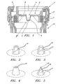
- Figure 1 represents a part of a closure 1 according to the present invention.
- This closure 1 comprises a base 2 provided with a skirt 3 at is periphery.
- the skirt 3 extends in a general transversal direction to one side of the base 2.
- the base 2 comprises a piercable part 4 that is defined by a sidewall 5 extending transversally with respect to the base 2 and a bottom 6, thereby creating an indent in the base 2.
- the base 2 comprises a cylindrical wall section 7 surrounding the piercable part 4 and extending to the same side of the base as the indent and the skirt 3. Extending radially from the cylindrical wall section 7 towards the piercable part 4 are provided several triangular ribs 8 ensuring the closures stability.
- the base 2 may comprise an access port 9 distinct from the piercable part 4.
- the access port is located at the periphery of the base 2, while the piercable part 4 is located centrally in the base 2.
- Figure 2 represents a partial view of a closure according the present invention, wherein the skirt 3 and the ribs 8 on the cylindrical wall section have been omitted for reason of clarity.
- the sidewall 5 and/or the bottom 6 of the piercable part 4 comprise several lines 10 of weakened material strength, said lines 10 dividing the sidewall 5 and bottom 6 in several wedge formed parts 11.
- the weakened material strength can be obtained by executing the lines 10 with reduced material thickness in view of the wedged parts 11.
- the lines 10 of weakened material strength extend over both the sidewall 5 and the bottom 6 to join in a point.
- the lines 10 are provided in either the sidewall 5 ( figure 3 ) or the bottom 6 ( figure 4 ) alone.
- a optional circular line 10 can be provided at the periphery of the bottom 6.
- the sidewall 5 is conically shaped, converging from the base 2 towards the bottom 6 of the indent.
- Figure 5 represents an embodiment, wherein the sidewall converges in to a point 12, where the lines 10 join each other.
- the closure 1 When correctly applied on a container 13, the closure 1 seals an opening thereof, whereby the inside of the container is accessible through the piercable part 4.
- the indent defining the pierceable part 4 hereby preferably extends into the container 13.
- the sidewall and/or bottom When piercing the piercable part with a dispensing means, the sidewall and/or bottom will be ruptured in a controlled manner along the different lines 10 provided therein and the resulting wedge formed parts 11 will hinge away from each other towards the base 2 of the closure such that an access to the container is created.
- the piercable part 4 must be entirely or partially over-moulded with an elastic material.
- the over-mould is applied on that side of the piercable part that is meant to be directed outside the container when the closure is correctly applied thereon.
- a first function of the over-mould preferably is to protect the lines 10 of weakened material strength from accidental rupture.
- the over-mould preferably forms an additional aid against permeation prior and during piercing of the piercable part.
- active scavenging components can be comprised in the over-mould.
- the over-mould is preferably designed to have a sealing function with respect to a needle inserted in the container through the piercable part 4 so that the acquired sealing can prevent leakage from inside the container to outside the container and/or prevent permeation of gases in or outside the container via the interface of wedge and inserted needle.
- the material wherein the closure or at least the piercable part is manufactured can be chosen such that the wedge formed parts 11 can serve as hooks preventing a dispensing means inserted in the closure to be retreated. This is especially desirable for hygiene reasons since contamination of the part of the dispensing means inserted in the container can be prevented. If desired, the retreat of the dispensing tube can be prevented even further by providing hooks on the dispensing means that can cooperate with the hooks formed by the wedge formed parts 11.
- closure is especially useful for closing containers for storing carbonated beverages such as beer.
- a constant overpressure is present in view of ambient pressure, whereby the overpressure presses the different wedge formed parts 11 towards each other prior to opening the container.
- accidental rupture of the piercable part from inside the container is unlikely.
- Bag-in-containers also referred to as bag-in-bottles or bag-in-boxes depending on the geometry of the outer vessel, all terms considered herein as being comprised within the meaning of the term bag-in-container, are a family of liquid dispensing packaging consisting of an outer container comprising an opening to the atmosphere --the mouth-- and which contains a collapsible inner bag joined to said container and opening to the atmosphere at the region of said mouth.
- the system must comprise at least one vent fluidly connecting the atmosphere to the region between the inner bag and the outer container in order to control the pressure in said region to squeeze the inner bag and thus dispense the liquid contained therein.
- bag-in-containers were --and still are-- produced by independently producing an inner bag provided with a specific neck closure assembly and a structural container (usually in the form of a bottle).
- the bag is inserted into the fully formed bottle opening and fixed thereto by means of the neck closure assembly, which comprises one opening to the interior of the bag and vents fluidly connecting the space between bag and bottle to the atmosphere; examples of such constructions can be found inter alia in US-A-3484011 , US-A-3450254 , US-A-4,330,066 , and US-A-4892230 .
Landscapes
- Engineering & Computer Science (AREA)
- Mechanical Engineering (AREA)
- Closures For Containers (AREA)
Description
- The present invention is directed to a closure of the type having a base comprising a piercable part, the piercable part being defined by a sidewall extending transversally with respect to the base and a bottom thereby creating a indent in the base, said sidewall and/or bottom comprising several lines of weakened material strength. Particularly the invention concerns a closure of the above mentioned type for sealing container, especially containers for storing carbonated beverages such as beer.
- It is generally known to seal containers with closures defining a piercable part, where through a dispensing means can be inserted into the container thereby allowing dispensing the fluid stored therein. With the increasing demand for home appliance systems for dispensing beverages stored in small sized containers, new requirements arise in terms of handling safety, hygiene, and durability.
- Closures have been cited in the art that comprise a piercable part formed by a flexible diaphragm. Such closures however can only be pierced when using a needle or dispensing means having a sharp tip, resulting in a safety hazard that is undesired for home appliances. Other types of closures such as cited in
GB 1,074,165 GB 1,074,165 -
US6716396 discloses a cap which can form an essentially leak-proof seal with a vessel capable of receiving fluid specimens for clinical analysis and diagnosis. To minimize potentially contaminating contact between the fluid specimen and humans or the environment, the cap disclosed inUS6716396 is penetrable by a plastic pipette tip or other fluid transfer device, and may include a plurality of striations which further improve penetrability of the cap. In this way, substances can be dispensed into or withdrawn from the vessel without having to physically separate the cap from the vessel. - It is an object of the present invention to overcome the above drawbacks while at the same time providing a closure with a piercable part allowing safe usage, good hygiene and sufficient durability, in particular to seal containers to be used in home appliance systems for dispensing beverages such as beer.
- closure having a base comprising a pierceable part, the pierceable part being defined by a sidewall extending transversally with respect to the base and a bottom, said sidewall and/or bottom comprising several lines of weakened material strength dividing the sidewall and/or bottom) in several wedge formed parts, characterized in that, said pierceable part is at least partially over-moulded with an elastic material such as to form, a seal with respect to a needle inserted in the container through the piercable part to prevent leakage from inside the container to outside the container and/or prevent permeation of gases in or outside the container via the interface of wedge and inserted needle.
- Said lines preferably extend in both the sidewall and the bottom of the piercable part.
- Preferably, the lines of weakened material strength have a reduced material thickness.
- According to a preferred embodiment, the indent has a conically shaped sidewall that may converge up to a point.
- According to a further embodiment, the closure preferably comprises a skirt extending transversally from the base while the conical sidewall of the piercable part extends to a same side of the base as the skirt.
- The present invention also concerns a container being provided with such a closure.
- The present invention concerns a closure having a base comprising a piercable part, the piercable part being defined by a sidewall extending transversally with respect to the base and a bottom, said sidewall and/or bottom comprising several lines of weakened material strength, characterized in that said lines divide the sidewall and/or bottom in several wedge formed parts.
- An advantage of a closure according to the present invention is that it can easily be pierced by a dispensing means with a rounded tip and that due to the configuration of the lines of weakened material strength, no material of the closure falls into the container during piercing.
- Another advantage of the closure according the present invention is that due to the combination of both the indent and the configuration of the lines of weakened material strength, accidental rupture of the piercable part due to overpressure in the container sealed by the closure is reduced. Indeed, when overpressure occurs in the container, the different wedge formed parts will be pressed towards each other instead of out of each other, such that accidental rupture can be minimized. Moreover, the above design of the closure facilitates piercing of the container as exerting pressure from outside the container on the piercable part, will drive the wedge formed parts apart.
- The above advantages will be even enhanced in case the indent has a conical sidewall, converging to that side of the closure which in normal use extends into the container, i.e. when the indent extends on a same side of the base of the closure as the skirt.
- The material wherein the closure or at least the piercable part is manufactured can be chosen such that the wedge formed parts can serve as hooks preventing a dispensing means inserted in the closure to be retreated. This is especially desirable for hygiene reasons since contamination of the part of the dispensing means inserted in the container can be prevented.
- In order to better explain the characteristics of the invention, the following preferred embodiments of an assembly according to the invention is given as non-limitative example, with reference to the accompanying drawings, in which:
-
Figure 1 represents a cross-section of a closure according to the present invention when provided on a container; -
Figures 2 to 5 represent simplified perspective views according arrow P, of several possible configurations of a base of a closure according the present invention. -
Figure 1 represents a part of a closure 1 according to the present invention. This closure 1 comprises abase 2 provided with askirt 3 at is periphery. Theskirt 3 extends in a general transversal direction to one side of thebase 2. - The
base 2 comprises apiercable part 4 that is defined by asidewall 5 extending transversally with respect to thebase 2 and abottom 6, thereby creating an indent in thebase 2. - In the represented embodiment, the
base 2 comprises acylindrical wall section 7 surrounding thepiercable part 4 and extending to the same side of the base as the indent and theskirt 3. Extending radially from thecylindrical wall section 7 towards thepiercable part 4 are provided severaltriangular ribs 8 ensuring the closures stability. - Finally, the
base 2 may comprise anaccess port 9 distinct from thepiercable part 4. In this case, the access port is located at the periphery of thebase 2, while thepiercable part 4 is located centrally in thebase 2. -
Figure 2 represents a partial view of a closure according the present invention, wherein theskirt 3 and theribs 8 on the cylindrical wall section have been omitted for reason of clarity. - According to the present invention, the
sidewall 5 and/or thebottom 6 of thepiercable part 4 compriseseveral lines 10 of weakened material strength, saidlines 10 dividing thesidewall 5 andbottom 6 in several wedge formedparts 11. In the case that the closure is manufactured in a thermoplastic material such as polyesters or polyolefins, the weakened material strength can be obtained by executing thelines 10 with reduced material thickness in view of thewedged parts 11. - In the embodiment represented in
figure 2 thelines 10 of weakened material strength extend over both thesidewall 5 and thebottom 6 to join in a point. - In the embodiments represented in
figures 3 and 4 , thelines 10 are provided in either the sidewall 5 (figure 3 ) or the bottom 6 (figure 4 ) alone. In embodiment represented infigure 3 , a optionalcircular line 10 can be provided at the periphery of thebottom 6. - In all represented embodiments of
figures 1 to 4 , thesidewall 5 is conically shaped, converging from thebase 2 towards thebottom 6 of the indent. -
Figure 5 represents an embodiment, wherein the sidewall converges in to apoint 12, where thelines 10 join each other. - When correctly applied on a
container 13, the closure 1 seals an opening thereof, whereby the inside of the container is accessible through thepiercable part 4. As represented infigure 1 , the indent defining thepierceable part 4 hereby preferably extends into thecontainer 13. - When piercing the piercable part with a dispensing means, the sidewall and/or bottom will be ruptured in a controlled manner along the
different lines 10 provided therein and the resulting wedge formedparts 11 will hinge away from each other towards thebase 2 of the closure such that an access to the container is created. - Clearly, as the wedge formed
parts 11 remain attached to thebase 2, no parts of the closure will fall into the container. - It is further noted that the
piercable part 4 must be entirely or partially over-moulded with an elastic material. The over-mould is applied on that side of the piercable part that is meant to be directed outside the container when the closure is correctly applied thereon. - A first function of the over-mould preferably is to protect the
lines 10 of weakened material strength from accidental rupture. Secondly the over-mould preferably forms an additional aid against permeation prior and during piercing of the piercable part. To further prevent permeation, active scavenging components can be comprised in the over-mould. Thirdly, the over-mould is preferably designed to have a sealing function with respect to a needle inserted in the container through thepiercable part 4 so that the acquired sealing can prevent leakage from inside the container to outside the container and/or prevent permeation of gases in or outside the container via the interface of wedge and inserted needle. - The material wherein the closure or at least the piercable part is manufactured can be chosen such that the wedge formed
parts 11 can serve as hooks preventing a dispensing means inserted in the closure to be retreated. This is especially desirable for hygiene reasons since contamination of the part of the dispensing means inserted in the container can be prevented. If desired, the retreat of the dispensing tube can be prevented even further by providing hooks on the dispensing means that can cooperate with the hooks formed by the wedge formedparts 11. - It is remarked that the closure is especially useful for closing containers for storing carbonated beverages such as beer. In such containers a constant overpressure is present in view of ambient pressure, whereby the overpressure presses the different wedge formed
parts 11 towards each other prior to opening the container. As such, accidental rupture of the piercable part from inside the container is unlikely. - The closure according to the present invention, especially when comprising the above mentioned access port, are found to be especially suited to seal containers of the type generally known as bag-in-container. Bag-in-containers, also referred to as bag-in-bottles or bag-in-boxes depending on the geometry of the outer vessel, all terms considered herein as being comprised within the meaning of the term bag-in-container, are a family of liquid dispensing packaging consisting of an outer container comprising an opening to the atmosphere --the mouth-- and which contains a collapsible inner bag joined to said container and opening to the atmosphere at the region of said mouth. The system must comprise at least one vent fluidly connecting the atmosphere to the region between the inner bag and the outer container in order to control the pressure in said region to squeeze the inner bag and thus dispense the liquid contained therein.
- Traditionally, bag-in-containers were --and still are-- produced by independently producing an inner bag provided with a specific neck closure assembly and a structural container (usually in the form of a bottle). The bag is inserted into the fully formed bottle opening and fixed thereto by means of the neck closure assembly, which comprises one opening to the interior of the bag and vents fluidly connecting the space between bag and bottle to the atmosphere; examples of such constructions can be found inter alia in
US-A-3484011 ,US-A-3450254 ,US-A-4,330,066 , andUS-A-4892230 . - The present invention is by no means limited to the embodiments described above and represented in the accompanying figures; on the contrary, such an assembly of a container and a closure comprising an overpressure relief system can be made in various executions while still remaining within the scope of the appended claims.
Claims (11)
- A closure having a base (2) comprising a pierceable part (4), the pierceable part (4) being defined by a sidewall (5) extending transversally with respect to the base (2) and a bottom (6), said sidewall (5) and/or bottom (6) comprising several lines (10) of weakened material strength dividing the sidewall (5) and/or bottom (6) in several wedge formed parts (11), characterized in that, said pierceable part (4) is at least partially over-moulded with an elastic material such as to form a seal with respect to a needle inserted in the container through the piercable part (4) to prevent leakage from inside the container to outside the container and/or prevent permeation of gases in or outside the container via the interface of wedge and inserted needle.
- The closure according to claim 1, characterized in that the lines (10) of weakened material strength have a reduced material thickness.
- The closure according to any of claims 1 and 2, characterized in that pierceable part (4) has a conically shaped sidewall (5).
- The closure according to any of the preceding claims, characterized in that both the sidewall (5) and the bottom (6) are provided with said lines (10) of weakened material strength.
- The closure according to any of the preceding claims, characterized in that the sidewall (5) converges up to a point (12).
- The closure according to any of the preceding claims, characterized in that the closure (1) comprises a skirt (3) extending transversally from the base (2) and in that the conical sidewall (5) of the pierceable part (4) extends to a same side of the base (2) as the skirt (3).
- The closure according to any of the preceding claims, characterized in that it comprises an access port (9) distinct from the pierceable part (4).
- The closure according to claim 7, characterized in that the pierceable part (4) is located centrally in the base (2), the access port (9) being located at the periphery of said base (2).
- The closure according to any of the preceding claims, wherein the over-moulded elastic material provides at least one of the following functions to the closure:(a) protecting the lines (10) of weakened material strength from accidental rupture, and/or(b) forming an additional aid against permeation prior and during piercing of the piercable part,
- A container being provided with a closure (1) as identified in any of the preceding claims.
- The container according to claim 10, designed for containing a carbonated beverage.
Priority Applications (1)
| Application Number | Priority Date | Filing Date | Title |
|---|---|---|---|
| EP09703041.5A EP2238041B1 (en) | 2008-01-15 | 2009-01-15 | A closure |
Applications Claiming Priority (3)
| Application Number | Priority Date | Filing Date | Title |
|---|---|---|---|
| EP08100516A EP2080708A1 (en) | 2008-01-15 | 2008-01-15 | A closure |
| PCT/EP2009/050441 WO2009090223A1 (en) | 2008-01-15 | 2009-01-15 | A closure |
| EP09703041.5A EP2238041B1 (en) | 2008-01-15 | 2009-01-15 | A closure |
Publications (2)
| Publication Number | Publication Date |
|---|---|
| EP2238041A1 EP2238041A1 (en) | 2010-10-13 |
| EP2238041B1 true EP2238041B1 (en) | 2015-07-29 |
Family
ID=39494404
Family Applications (2)
| Application Number | Title | Priority Date | Filing Date |
|---|---|---|---|
| EP08100516A Withdrawn EP2080708A1 (en) | 2008-01-15 | 2008-01-15 | A closure |
| EP09703041.5A Active EP2238041B1 (en) | 2008-01-15 | 2009-01-15 | A closure |
Family Applications Before (1)
| Application Number | Title | Priority Date | Filing Date |
|---|---|---|---|
| EP08100516A Withdrawn EP2080708A1 (en) | 2008-01-15 | 2008-01-15 | A closure |
Country Status (8)
| Country | Link |
|---|---|
| US (1) | US10543963B2 (en) |
| EP (2) | EP2080708A1 (en) |
| CN (1) | CN101959765B (en) |
| BR (1) | BRPI0905740B1 (en) |
| DK (1) | DK2238041T3 (en) |
| ES (1) | ES2549802T3 (en) |
| RU (1) | RU2502655C2 (en) |
| WO (1) | WO2009090223A1 (en) |
Cited By (2)
| Publication number | Priority date | Publication date | Assignee | Title |
|---|---|---|---|---|
| US11591202B2 (en) | 2017-05-19 | 2023-02-28 | Heineken Supply Chain B.V. | Beverage dispensing assembly and beverage container |
| US11724930B2 (en) | 2017-05-19 | 2023-08-15 | Heineken Supply Chain B.V. | Beverage dispensing assembly and beverage container |
Families Citing this family (13)
| Publication number | Priority date | Publication date | Assignee | Title |
|---|---|---|---|---|
| WO2011051475A1 (en) | 2009-10-30 | 2011-05-05 | Ab Inbev Nv | Beverage dispenser |
| EP2405164A1 (en) | 2010-07-08 | 2012-01-11 | Anheuser-Bush Inbev NV | Resilient closure for pressure driven dispensing container |
| EP2447208A1 (en) | 2010-10-29 | 2012-05-02 | AB InBev NV | Dispensing appliance provided with a hinged hood |
| EP2514711A1 (en) | 2011-04-18 | 2012-10-24 | Anheuser-Busch InBev S.A. | Liquid dispensing appliance comprising a solid gas-adsorbent |
| EP2719656A1 (en) | 2012-10-11 | 2014-04-16 | Anheuser-Busch InBev S.A. | Keg connector |
| US9200120B2 (en) | 2013-05-28 | 2015-12-01 | Xerox Corporation | Blanket materials for indirect printing methods |
| DE102013105761A1 (en) * | 2013-06-04 | 2014-12-04 | Krones Ag | Closure for beverage bottle with possibility to supply gaseous medium |
| EP2987767A1 (en) | 2014-08-19 | 2016-02-24 | Anheuser-Busch InBev S.A. | Beverage dispensing appliance for multiple containers |
| EP3173373A1 (en) | 2015-11-26 | 2017-05-31 | Anheuser-Busch InBev S.A. | Polymeric keg connector |
| NL2017109B1 (en) | 2016-07-05 | 2018-01-12 | Heineken Supply Chain Bv | Beverage dispensing assembly and beverage container |
| BE1026635B1 (en) | 2018-09-20 | 2020-04-21 | Anheuser Busch Inbev Sa | Kit for dispensing a beverage through a dispensing tube that includes a dispensing valve |
| US20200109818A1 (en) * | 2018-10-09 | 2020-04-09 | Nuance Designs Of Ct, Llc | Low puncture force gas canister |
| IT202200004763A1 (en) * | 2022-03-11 | 2023-09-11 | Goglio Spa | Degassing valve for an airtight container |
Citations (1)
| Publication number | Priority date | Publication date | Assignee | Title |
|---|---|---|---|---|
| WO2007120719A2 (en) * | 2006-04-10 | 2007-10-25 | Medical Instill Technologies, Inc. | Ready to drink container with nipple and needle penetrable and laser resealable portion, and related method |
Family Cites Families (65)
| Publication number | Priority date | Publication date | Assignee | Title |
|---|---|---|---|---|
| US1694851A (en) * | 1927-09-14 | 1928-12-11 | Glass William | Bottle cap |
| US2085392A (en) * | 1934-12-19 | 1937-06-29 | Sharp & Dohme Inc | Container with lyophilic biologically-active substances, etc. |
| US2467979A (en) * | 1948-02-14 | 1949-04-19 | Fmc Corp | High-speed vacuum sealing cap |
| DE814258C (en) | 1949-07-05 | 1951-09-20 | Karl Hoffelner | Bottle cap |
| DE969306C (en) | 1952-11-15 | 1958-05-22 | Karl Rettmeyer | Sheet metal lid for marinade jars, preserving jars or the like. |
| DE1300463B (en) * | 1957-10-03 | 1969-07-31 | Sauer Wilhelm | Closure device for a container to be interchangeably connected to a spray gun |
| US3047177A (en) * | 1957-11-07 | 1962-07-31 | Baxter Laboratories Inc | Closure system |
| US3144154A (en) * | 1962-12-10 | 1964-08-11 | Owens Illinois Glass Co | Venting closure |
| US3348728A (en) * | 1965-01-04 | 1967-10-24 | Grace W R & Co | Pressure vessels |
| GB1074165A (en) | 1965-06-01 | 1965-06-28 | Sure Form Plastics Ltd | Improvements in and relating to shives for casks and kegs |
| DE1532396A1 (en) * | 1966-11-28 | 1969-10-02 | Bender Werke Gmbh | Bottle cap |
| US3450254A (en) | 1967-04-05 | 1969-06-17 | Colgate Palmolive Co | Package and receptacle |
| US3484011A (en) | 1968-04-16 | 1969-12-16 | William Greenhalgh | Disposable container liner and advertising means |
| US3628681A (en) * | 1969-10-06 | 1971-12-21 | Plastics Consulting And Mfg Co | Stopper |
| JPS549119B1 (en) * | 1970-09-16 | 1979-04-21 | ||
| US3907146A (en) * | 1973-11-15 | 1975-09-23 | Mack Robert Fields | Primary closure |
| US3966071A (en) * | 1975-05-01 | 1976-06-29 | Northup John D | Venting bottle closure |
| GB1545293A (en) | 1976-03-19 | 1979-05-10 | Dematex Dev & Invest | Stopper for vial-like tubes |
| US4159790A (en) * | 1977-12-19 | 1979-07-03 | Bailey Vincent R | Dispensing container |
| US4330066A (en) | 1980-11-21 | 1982-05-18 | Robert Berliner | Receptacle with collapsible internal container |
| US4365721A (en) * | 1981-07-10 | 1982-12-28 | Sunbeam Plastics Corporation | Child resistant closure and container assembly |
| US4635814A (en) * | 1983-09-16 | 1987-01-13 | Rheem Manufacturing Company | Lined receptacles |
| US4700860A (en) * | 1986-03-31 | 1987-10-20 | Owens-Illinois, Inc. | Tamper indicating vacuum package |
| US4984713A (en) * | 1987-03-31 | 1991-01-15 | Chambers Gary C | Carbonated beverage dispenser |
| US4784299A (en) * | 1987-04-03 | 1988-11-15 | Johnson Enterprises, Inc. | Tap with spaced product and gas tubes |
| US4892230A (en) | 1988-02-08 | 1990-01-09 | Lynn Jr Arthur E | Carbonated beverage bottle |
| JPH04501994A (en) * | 1988-11-28 | 1992-04-09 | ジョセフ パーソンズ ノミニーズ プロプライエタリー リミテッド | cap |
| JPH02162229A (en) * | 1988-12-16 | 1990-06-21 | Terumo Corp | liquid collection tube |
| US5031787A (en) * | 1989-09-01 | 1991-07-16 | Anchor Hocking Packaging Company | Low height floating disk closure |
| US5335821A (en) * | 1992-09-11 | 1994-08-09 | Now Technologies, Inc. | Liquid chemical container and dispensing system |
| US5328063A (en) * | 1993-06-10 | 1994-07-12 | Creative Packaging Corp. | Venting closure cap |
| US5810185A (en) * | 1995-03-02 | 1998-09-22 | Groesbeck; Robert Clay | Reclosable bottle closure for carbonated beverages and the like |
| US5935758A (en) | 1995-04-20 | 1999-08-10 | Imation Corp. | Laser induced film transfer system |
| AU2501997A (en) | 1996-05-09 | 1997-12-05 | Crown Cork Ag | Container cap and container mouth |
| AU3382297A (en) * | 1996-06-07 | 1998-01-05 | Claude R. Litto | Preservation and dispensation by volumetric displacement |
| CA2181828C (en) * | 1996-07-22 | 2002-01-15 | Richard Lamoureux | One-piece cap for liquid dispenser container |
| US5788196A (en) * | 1996-09-26 | 1998-08-04 | Forman; Peter A. | Support stand for a chafing dish |
| US5960972A (en) * | 1996-11-15 | 1999-10-05 | Constancio Larguia, Sr. | Container cap with interlocked safety closure |
| US5853096A (en) * | 1996-11-25 | 1998-12-29 | Bartur; Maya H. | Pressure equalizing and foam eliminating cap |
| US5904965A (en) * | 1997-04-24 | 1999-05-18 | Nomaco, Inc. | Synthetic closure |
| ATE215486T1 (en) * | 1997-11-03 | 2002-04-15 | Kurt Oberhofer | CLOSURE WITH PRESSURE COMPENSATION VALVE FOR A LIQUID TANK |
| DE19751411C1 (en) * | 1997-11-14 | 1999-01-14 | Mannesmann Ag | Composite fibre-reinforced pressurised gas tank including liner with end neck sections |
| US5934500A (en) * | 1998-02-17 | 1999-08-10 | Allergan | Container sealing structure for flexible containers |
| US6206230B1 (en) * | 1998-03-25 | 2001-03-27 | Crown Cork & Seal Technologies Corporation | Single piece, push-pull dispensing closure and assembly |
| EP0982234A1 (en) * | 1998-08-22 | 2000-03-01 | Crown Cork & Seal Technologies Corporation | Closure cap |
| US6716396B1 (en) * | 1999-05-14 | 2004-04-06 | Gen-Probe Incorporated | Penetrable cap |
| US6202871B1 (en) * | 1999-08-27 | 2001-03-20 | Crown Cork & Seal Technologies Corporation | Vented beverage closure |
| DE19952214B4 (en) | 1999-10-29 | 2005-02-10 | Henzi-Breuer, Bianca | Cup-shaped screw cap |
| EP1138609A1 (en) | 2000-03-28 | 2001-10-04 | L & M SERVICES B.V. | Container closure |
| JP4443013B2 (en) * | 2000-08-01 | 2010-03-31 | 花王株式会社 | Double container cap |
| JP4749572B2 (en) | 2001-03-13 | 2011-08-17 | 大成化工株式会社 | Dispensing container plug structure |
| US20040060598A1 (en) * | 2001-06-13 | 2004-04-01 | Hal Danby | Vacuum demand flow valve |
| GB2383995B (en) * | 2002-01-11 | 2005-12-07 | Portola Packaging Ltd | Closure with pressure release system |
| US6848599B2 (en) * | 2002-08-22 | 2005-02-01 | Illinois Tool Works Inc. | Adhesive container and method of filling |
| GB0227938D0 (en) * | 2002-11-29 | 2003-01-08 | Interbrew Sa | Interlocking collar for securing alcohol containing bag to keg container |
| JP4006332B2 (en) * | 2002-12-26 | 2007-11-14 | 勝利 増田 | Fluid storage container |
| US7367479B2 (en) * | 2004-03-11 | 2008-05-06 | Sitz William G | Device to retain carbonation |
| DE602004011039T2 (en) | 2004-07-09 | 2009-01-02 | Sara Lee/De N.V. | closure device |
| EP1657177A1 (en) * | 2004-11-11 | 2006-05-17 | Crown Packaging Technology, Inc | Self-Venting closure |
| GB2426508A (en) * | 2005-05-26 | 2006-11-29 | Abu-Turab Mirmohammadi | Non-spill bottle cap for water dispensers |
| US7819286B2 (en) * | 2006-07-25 | 2010-10-26 | Kegx Llc | Beer keg and method of assembly |
| US8596478B2 (en) * | 2007-06-07 | 2013-12-03 | Andrew Gadzic | Cap assembly with attached flexible liner for use with a container to hold contents therein |
| JP5416117B2 (en) * | 2007-08-28 | 2014-02-12 | インテグリス・インコーポレーテッド | Fluid distribution method and apparatus |
| FR2937016B1 (en) * | 2008-10-09 | 2010-11-26 | Tetra Laval Holdings & Finance | DECOUPETED WEAKENING LINE PLUG AND METHOD OF MANUFACTURING THE PLUG |
| US8434633B2 (en) * | 2009-01-28 | 2013-05-07 | Fres-Co System Usa, Inc. | One-way valve for flexible package and package including a one-way valve |
-
2008
- 2008-01-15 EP EP08100516A patent/EP2080708A1/en not_active Withdrawn
-
2009
- 2009-01-15 CN CN2009801074993A patent/CN101959765B/en active Active
- 2009-01-15 BR BRPI0905740-4A patent/BRPI0905740B1/en active IP Right Grant
- 2009-01-15 EP EP09703041.5A patent/EP2238041B1/en active Active
- 2009-01-15 WO PCT/EP2009/050441 patent/WO2009090223A1/en not_active Ceased
- 2009-01-15 RU RU2010132840/12A patent/RU2502655C2/en active
- 2009-01-15 DK DK09703041.5T patent/DK2238041T3/en active
- 2009-01-15 ES ES09703041.5T patent/ES2549802T3/en active Active
- 2009-01-15 US US12/812,874 patent/US10543963B2/en active Active
Patent Citations (1)
| Publication number | Priority date | Publication date | Assignee | Title |
|---|---|---|---|---|
| WO2007120719A2 (en) * | 2006-04-10 | 2007-10-25 | Medical Instill Technologies, Inc. | Ready to drink container with nipple and needle penetrable and laser resealable portion, and related method |
Cited By (2)
| Publication number | Priority date | Publication date | Assignee | Title |
|---|---|---|---|---|
| US11591202B2 (en) | 2017-05-19 | 2023-02-28 | Heineken Supply Chain B.V. | Beverage dispensing assembly and beverage container |
| US11724930B2 (en) | 2017-05-19 | 2023-08-15 | Heineken Supply Chain B.V. | Beverage dispensing assembly and beverage container |
Also Published As
| Publication number | Publication date |
|---|---|
| WO2009090223A1 (en) | 2009-07-23 |
| EP2080708A1 (en) | 2009-07-22 |
| ES2549802T3 (en) | 2015-11-02 |
| EP2238041A1 (en) | 2010-10-13 |
| US20110024422A1 (en) | 2011-02-03 |
| BRPI0905740B1 (en) | 2019-09-17 |
| US10543963B2 (en) | 2020-01-28 |
| RU2502655C2 (en) | 2013-12-27 |
| BRPI0905740A2 (en) | 2017-03-01 |
| DK2238041T3 (en) | 2015-10-19 |
| CN101959765A (en) | 2011-01-26 |
| CN101959765B (en) | 2012-10-10 |
| RU2010132840A (en) | 2012-02-27 |
Similar Documents
| Publication | Publication Date | Title |
|---|---|---|
| DK2238041T3 (en) | Closure | |
| EP1996505B1 (en) | Puncturable cap and piercer | |
| RU2605177C2 (en) | Vessel corking device containing means of additive introduction into vessel contents | |
| CN101415615B (en) | Container assembly and pressure-responsive penetrable cap for the same | |
| US8490786B2 (en) | Inverted dome to supply dose | |
| US6305576B1 (en) | Cartridge for aseptically holding and dispensing a fluid material, and a container and method for aseptically holding and mixing the fluid material | |
| US4177938A (en) | Container with mixing cartridge | |
| US4620638A (en) | Cap for opening and extracting the contents of a vessel | |
| RU2438797C1 (en) | Device for separate storage of medical or pharmaceutical preparations and fluid and for mixing them prior to issuing | |
| US4325496A (en) | Filling-dispensing closure for a bag-like container | |
| EP3307642B1 (en) | Piercing valve assembly and fluid transfer device therewith | |
| US20080237235A1 (en) | Resealable beverage container | |
| US4011961A (en) | Plastic container and breakable sealing unit ultrasonically welded thereto | |
| US9493278B2 (en) | Penetrable plastics material seal for sealing containers | |
| GB2279069A (en) | Container | |
| EP0026055A1 (en) | Filling-dispensing neck and closure member combination for a bag-like container | |
| US20150174542A1 (en) | Multi-ingredient mixing device | |
| US4053648A (en) | Bottle for sterile dispensing of flowable contents | |
| EP3768603B1 (en) | Dispensing system | |
| US20040007587A1 (en) | Membrane piercing closure | |
| USRE29916E (en) | Bottle for sterile dispensing of flowable contents | |
| US20030201239A1 (en) | Radially compressed self-sealing septum | |
| CN212855328U (en) | Packaging container | |
| RU219778U1 (en) | CLOSURE FOR CONTAINER | |
| JP7091051B2 (en) | Food container cap |
Legal Events
| Date | Code | Title | Description |
|---|---|---|---|
| PUAI | Public reference made under article 153(3) epc to a published international application that has entered the european phase |
Free format text: ORIGINAL CODE: 0009012 |
|
| 17P | Request for examination filed |
Effective date: 20100816 |
|
| AK | Designated contracting states |
Kind code of ref document: A1 Designated state(s): AT BE BG CH CY CZ DE DK EE ES FI FR GB GR HR HU IE IS IT LI LT LU LV MC MK MT NL NO PL PT RO SE SI SK TR |
|
| AX | Request for extension of the european patent |
Extension state: AL BA RS |
|
| RAX | Requested extension states of the european patent have changed |
Extension state: RS Payment date: 20100816 |
|
| 17Q | First examination report despatched |
Effective date: 20111201 |
|
| GRAP | Despatch of communication of intention to grant a patent |
Free format text: ORIGINAL CODE: EPIDOSNIGR1 |
|
| INTG | Intention to grant announced |
Effective date: 20150513 |
|
| GRAS | Grant fee paid |
Free format text: ORIGINAL CODE: EPIDOSNIGR3 |
|
| GRAA | (expected) grant |
Free format text: ORIGINAL CODE: 0009210 |
|
| AK | Designated contracting states |
Kind code of ref document: B1 Designated state(s): AT BE BG CH CY CZ DE DK EE ES FI FR GB GR HR HU IE IS IT LI LT LU LV MC MK MT NL NO PL PT RO SE SI SK TR |
|
| AX | Request for extension of the european patent |
Extension state: RS |
|
| REG | Reference to a national code |
Ref country code: GB Ref legal event code: FG4D |
|
| REG | Reference to a national code |
Ref country code: CH Ref legal event code: EP |
|
| REG | Reference to a national code |
Ref country code: AT Ref legal event code: REF Ref document number: 739066 Country of ref document: AT Kind code of ref document: T Effective date: 20150815 |
|
| REG | Reference to a national code |
Ref country code: IE Ref legal event code: FG4D |
|
| REG | Reference to a national code |
Ref country code: DE Ref legal event code: R096 Ref document number: 602009032470 Country of ref document: DE |
|
| REG | Reference to a national code |
Ref country code: DK Ref legal event code: T3 Effective date: 20151016 |
|
| REG | Reference to a national code |
Ref country code: AT Ref legal event code: MK05 Ref document number: 739066 Country of ref document: AT Kind code of ref document: T Effective date: 20150729 |
|
| REG | Reference to a national code |
Ref country code: NL Ref legal event code: FP |
|
| REG | Reference to a national code |
Ref country code: LT Ref legal event code: MG4D |
|
| REG | Reference to a national code |
Ref country code: FR Ref legal event code: PLFP Year of fee payment: 8 |
|
| PG25 | Lapsed in a contracting state [announced via postgrant information from national office to epo] |
Ref country code: FI Free format text: LAPSE BECAUSE OF FAILURE TO SUBMIT A TRANSLATION OF THE DESCRIPTION OR TO PAY THE FEE WITHIN THE PRESCRIBED TIME-LIMIT Effective date: 20150729 Ref country code: LV Free format text: LAPSE BECAUSE OF FAILURE TO SUBMIT A TRANSLATION OF THE DESCRIPTION OR TO PAY THE FEE WITHIN THE PRESCRIBED TIME-LIMIT Effective date: 20150729 Ref country code: LT Free format text: LAPSE BECAUSE OF FAILURE TO SUBMIT A TRANSLATION OF THE DESCRIPTION OR TO PAY THE FEE WITHIN THE PRESCRIBED TIME-LIMIT Effective date: 20150729 Ref country code: GR Free format text: LAPSE BECAUSE OF FAILURE TO SUBMIT A TRANSLATION OF THE DESCRIPTION OR TO PAY THE FEE WITHIN THE PRESCRIBED TIME-LIMIT Effective date: 20151030 Ref country code: NO Free format text: LAPSE BECAUSE OF FAILURE TO SUBMIT A TRANSLATION OF THE DESCRIPTION OR TO PAY THE FEE WITHIN THE PRESCRIBED TIME-LIMIT Effective date: 20151029 |
|
| PG25 | Lapsed in a contracting state [announced via postgrant information from national office to epo] |
Ref country code: SE Free format text: LAPSE BECAUSE OF FAILURE TO SUBMIT A TRANSLATION OF THE DESCRIPTION OR TO PAY THE FEE WITHIN THE PRESCRIBED TIME-LIMIT Effective date: 20150729 Ref country code: AT Free format text: LAPSE BECAUSE OF FAILURE TO SUBMIT A TRANSLATION OF THE DESCRIPTION OR TO PAY THE FEE WITHIN THE PRESCRIBED TIME-LIMIT Effective date: 20150729 Ref country code: PL Free format text: LAPSE BECAUSE OF FAILURE TO SUBMIT A TRANSLATION OF THE DESCRIPTION OR TO PAY THE FEE WITHIN THE PRESCRIBED TIME-LIMIT Effective date: 20150729 Ref country code: PT Free format text: LAPSE BECAUSE OF FAILURE TO SUBMIT A TRANSLATION OF THE DESCRIPTION OR TO PAY THE FEE WITHIN THE PRESCRIBED TIME-LIMIT Effective date: 20151130 Ref country code: IS Free format text: LAPSE BECAUSE OF FAILURE TO SUBMIT A TRANSLATION OF THE DESCRIPTION OR TO PAY THE FEE WITHIN THE PRESCRIBED TIME-LIMIT Effective date: 20151129 Ref country code: HR Free format text: LAPSE BECAUSE OF FAILURE TO SUBMIT A TRANSLATION OF THE DESCRIPTION OR TO PAY THE FEE WITHIN THE PRESCRIBED TIME-LIMIT Effective date: 20150729 |
|
| PG25 | Lapsed in a contracting state [announced via postgrant information from national office to epo] |
Ref country code: EE Free format text: LAPSE BECAUSE OF FAILURE TO SUBMIT A TRANSLATION OF THE DESCRIPTION OR TO PAY THE FEE WITHIN THE PRESCRIBED TIME-LIMIT Effective date: 20150729 Ref country code: SK Free format text: LAPSE BECAUSE OF FAILURE TO SUBMIT A TRANSLATION OF THE DESCRIPTION OR TO PAY THE FEE WITHIN THE PRESCRIBED TIME-LIMIT Effective date: 20150729 |
|
| REG | Reference to a national code |
Ref country code: DE Ref legal event code: R097 Ref document number: 602009032470 Country of ref document: DE |
|
| PG25 | Lapsed in a contracting state [announced via postgrant information from national office to epo] |
Ref country code: RO Free format text: LAPSE BECAUSE OF FAILURE TO SUBMIT A TRANSLATION OF THE DESCRIPTION OR TO PAY THE FEE WITHIN THE PRESCRIBED TIME-LIMIT Effective date: 20150729 |
|
| PLBE | No opposition filed within time limit |
Free format text: ORIGINAL CODE: 0009261 |
|
| STAA | Information on the status of an ep patent application or granted ep patent |
Free format text: STATUS: NO OPPOSITION FILED WITHIN TIME LIMIT |
|
| 26N | No opposition filed |
Effective date: 20160502 |
|
| PG25 | Lapsed in a contracting state [announced via postgrant information from national office to epo] |
Ref country code: SI Free format text: LAPSE BECAUSE OF FAILURE TO SUBMIT A TRANSLATION OF THE DESCRIPTION OR TO PAY THE FEE WITHIN THE PRESCRIBED TIME-LIMIT Effective date: 20150729 Ref country code: LU Free format text: LAPSE BECAUSE OF FAILURE TO SUBMIT A TRANSLATION OF THE DESCRIPTION OR TO PAY THE FEE WITHIN THE PRESCRIBED TIME-LIMIT Effective date: 20160115 |
|
| REG | Reference to a national code |
Ref country code: CH Ref legal event code: PL |
|
| PG25 | Lapsed in a contracting state [announced via postgrant information from national office to epo] |
Ref country code: MC Free format text: LAPSE BECAUSE OF FAILURE TO SUBMIT A TRANSLATION OF THE DESCRIPTION OR TO PAY THE FEE WITHIN THE PRESCRIBED TIME-LIMIT Effective date: 20150729 |
|
| PG25 | Lapsed in a contracting state [announced via postgrant information from national office to epo] |
Ref country code: LI Free format text: LAPSE BECAUSE OF NON-PAYMENT OF DUE FEES Effective date: 20160131 Ref country code: CH Free format text: LAPSE BECAUSE OF NON-PAYMENT OF DUE FEES Effective date: 20160131 |
|
| REG | Reference to a national code |
Ref country code: FR Ref legal event code: PLFP Year of fee payment: 9 |
|
| PG25 | Lapsed in a contracting state [announced via postgrant information from national office to epo] |
Ref country code: MT Free format text: LAPSE BECAUSE OF FAILURE TO SUBMIT A TRANSLATION OF THE DESCRIPTION OR TO PAY THE FEE WITHIN THE PRESCRIBED TIME-LIMIT Effective date: 20150729 |
|
| REG | Reference to a national code |
Ref country code: FR Ref legal event code: PLFP Year of fee payment: 10 |
|
| PG25 | Lapsed in a contracting state [announced via postgrant information from national office to epo] |
Ref country code: HU Free format text: LAPSE BECAUSE OF FAILURE TO SUBMIT A TRANSLATION OF THE DESCRIPTION OR TO PAY THE FEE WITHIN THE PRESCRIBED TIME-LIMIT; INVALID AB INITIO Effective date: 20090115 Ref country code: CY Free format text: LAPSE BECAUSE OF FAILURE TO SUBMIT A TRANSLATION OF THE DESCRIPTION OR TO PAY THE FEE WITHIN THE PRESCRIBED TIME-LIMIT Effective date: 20150729 |
|
| PG25 | Lapsed in a contracting state [announced via postgrant information from national office to epo] |
Ref country code: MT Free format text: LAPSE BECAUSE OF FAILURE TO SUBMIT A TRANSLATION OF THE DESCRIPTION OR TO PAY THE FEE WITHIN THE PRESCRIBED TIME-LIMIT Effective date: 20160131 Ref country code: MK Free format text: LAPSE BECAUSE OF FAILURE TO SUBMIT A TRANSLATION OF THE DESCRIPTION OR TO PAY THE FEE WITHIN THE PRESCRIBED TIME-LIMIT Effective date: 20150729 Ref country code: TR Free format text: LAPSE BECAUSE OF FAILURE TO SUBMIT A TRANSLATION OF THE DESCRIPTION OR TO PAY THE FEE WITHIN THE PRESCRIBED TIME-LIMIT Effective date: 20150729 |
|
| PG25 | Lapsed in a contracting state [announced via postgrant information from national office to epo] |
Ref country code: BG Free format text: LAPSE BECAUSE OF FAILURE TO SUBMIT A TRANSLATION OF THE DESCRIPTION OR TO PAY THE FEE WITHIN THE PRESCRIBED TIME-LIMIT Effective date: 20150729 |
|
| PGFP | Annual fee paid to national office [announced via postgrant information from national office to epo] |
Ref country code: CZ Payment date: 20220117 Year of fee payment: 14 |
|
| P01 | Opt-out of the competence of the unified patent court (upc) registered |
Effective date: 20230527 |
|
| PG25 | Lapsed in a contracting state [announced via postgrant information from national office to epo] |
Ref country code: CZ Free format text: LAPSE BECAUSE OF NON-PAYMENT OF DUE FEES Effective date: 20230115 |
|
| PGFP | Annual fee paid to national office [announced via postgrant information from national office to epo] |
Ref country code: NL Payment date: 20260121 Year of fee payment: 18 |
|
| PGFP | Annual fee paid to national office [announced via postgrant information from national office to epo] |
Ref country code: GB Payment date: 20260123 Year of fee payment: 18 |
|
| PGFP | Annual fee paid to national office [announced via postgrant information from national office to epo] |
Ref country code: ES Payment date: 20260227 Year of fee payment: 18 |
|
| PGFP | Annual fee paid to national office [announced via postgrant information from national office to epo] |
Ref country code: DE Payment date: 20260121 Year of fee payment: 18 Ref country code: IE Payment date: 20260122 Year of fee payment: 18 Ref country code: DK Payment date: 20260126 Year of fee payment: 18 |
|
| PGFP | Annual fee paid to national office [announced via postgrant information from national office to epo] |
Ref country code: BE Payment date: 20260121 Year of fee payment: 18 Ref country code: IT Payment date: 20260126 Year of fee payment: 18 |
|
| PGFP | Annual fee paid to national office [announced via postgrant information from national office to epo] |
Ref country code: FR Payment date: 20260123 Year of fee payment: 18 |