EP2237749B1 - Modèles d endoprothèses à utiliser avec un ou plusieurs fils de déclenchement - Google Patents
Modèles d endoprothèses à utiliser avec un ou plusieurs fils de déclenchement Download PDFInfo
- Publication number
- EP2237749B1 EP2237749B1 EP09708866.0A EP09708866A EP2237749B1 EP 2237749 B1 EP2237749 B1 EP 2237749B1 EP 09708866 A EP09708866 A EP 09708866A EP 2237749 B1 EP2237749 B1 EP 2237749B1
- Authority
- EP
- European Patent Office
- Prior art keywords
- proximal
- stent
- bore
- apices
- distal
- Prior art date
- Legal status (The legal status is an assumption and is not a legal conclusion. Google has not performed a legal analysis and makes no representation as to the accuracy of the status listed.)
- Active
Links
- 239000000463 material Substances 0.000 claims description 26
- 238000003384 imaging method Methods 0.000 claims description 17
- 230000007704 transition Effects 0.000 claims description 17
- 238000000034 method Methods 0.000 claims description 11
- 230000008878 coupling Effects 0.000 claims description 6
- 238000010168 coupling process Methods 0.000 claims description 6
- 238000005859 coupling reaction Methods 0.000 claims description 6
- 239000003550 marker Substances 0.000 claims description 6
- 229910001000 nickel titanium Inorganic materials 0.000 description 8
- 230000008901 benefit Effects 0.000 description 6
- 230000006835 compression Effects 0.000 description 6
- 238000007906 compression Methods 0.000 description 6
- 206010002329 Aneurysm Diseases 0.000 description 5
- HLXZNVUGXRDIFK-UHFFFAOYSA-N nickel titanium Chemical compound [Ti].[Ti].[Ti].[Ti].[Ti].[Ti].[Ti].[Ti].[Ti].[Ti].[Ti].[Ni].[Ni].[Ni].[Ni].[Ni].[Ni].[Ni].[Ni].[Ni].[Ni].[Ni].[Ni].[Ni].[Ni] HLXZNVUGXRDIFK-UHFFFAOYSA-N 0.000 description 5
- 238000003698 laser cutting Methods 0.000 description 4
- 230000001154 acute effect Effects 0.000 description 3
- 229910001285 shape-memory alloy Inorganic materials 0.000 description 3
- 230000002411 adverse Effects 0.000 description 2
- 229910045601 alloy Inorganic materials 0.000 description 2
- 239000000956 alloy Substances 0.000 description 2
- 238000003486 chemical etching Methods 0.000 description 2
- 230000004069 differentiation Effects 0.000 description 2
- 239000013013 elastic material Substances 0.000 description 2
- 239000012530 fluid Substances 0.000 description 2
- PCHJSUWPFVWCPO-UHFFFAOYSA-N gold Chemical compound [Au] PCHJSUWPFVWCPO-UHFFFAOYSA-N 0.000 description 2
- 229910052737 gold Inorganic materials 0.000 description 2
- 239000010931 gold Substances 0.000 description 2
- 229910052751 metal Inorganic materials 0.000 description 2
- 239000002184 metal Substances 0.000 description 2
- 150000002739 metals Chemical class 0.000 description 2
- BASFCYQUMIYNBI-UHFFFAOYSA-N platinum Chemical compound [Pt] BASFCYQUMIYNBI-UHFFFAOYSA-N 0.000 description 2
- 229910000684 Cobalt-chrome Inorganic materials 0.000 description 1
- RTAQQCXQSZGOHL-UHFFFAOYSA-N Titanium Chemical compound [Ti] RTAQQCXQSZGOHL-UHFFFAOYSA-N 0.000 description 1
- HZEWFHLRYVTOIW-UHFFFAOYSA-N [Ti].[Ni] Chemical compound [Ti].[Ni] HZEWFHLRYVTOIW-UHFFFAOYSA-N 0.000 description 1
- 238000002399 angioplasty Methods 0.000 description 1
- 239000010952 cobalt-chrome Substances 0.000 description 1
- 230000000694 effects Effects 0.000 description 1
- 230000001939 inductive effect Effects 0.000 description 1
- 230000007246 mechanism Effects 0.000 description 1
- 239000007769 metal material Substances 0.000 description 1
- 229910052697 platinum Inorganic materials 0.000 description 1
- 229920000642 polymer Polymers 0.000 description 1
- 230000000452 restraining effect Effects 0.000 description 1
- 239000010935 stainless steel Substances 0.000 description 1
- 229910001220 stainless steel Inorganic materials 0.000 description 1
- 229910052715 tantalum Inorganic materials 0.000 description 1
- GUVRBAGPIYLISA-UHFFFAOYSA-N tantalum atom Chemical compound [Ta] GUVRBAGPIYLISA-UHFFFAOYSA-N 0.000 description 1
- 229920001169 thermoplastic Polymers 0.000 description 1
- 239000004416 thermosoftening plastic Substances 0.000 description 1
- 229910052719 titanium Inorganic materials 0.000 description 1
- 239000010936 titanium Substances 0.000 description 1
Images


Classifications
-
- A—HUMAN NECESSITIES
- A61—MEDICAL OR VETERINARY SCIENCE; HYGIENE
- A61F—FILTERS IMPLANTABLE INTO BLOOD VESSELS; PROSTHESES; DEVICES PROVIDING PATENCY TO, OR PREVENTING COLLAPSING OF, TUBULAR STRUCTURES OF THE BODY, e.g. STENTS; ORTHOPAEDIC, NURSING OR CONTRACEPTIVE DEVICES; FOMENTATION; TREATMENT OR PROTECTION OF EYES OR EARS; BANDAGES, DRESSINGS OR ABSORBENT PADS; FIRST-AID KITS
- A61F2/00—Filters implantable into blood vessels; Prostheses, i.e. artificial substitutes or replacements for parts of the body; Appliances for connecting them with the body; Devices providing patency to, or preventing collapsing of, tubular structures of the body, e.g. stents
- A61F2/95—Instruments specially adapted for placement or removal of stents or stent-grafts
-
- A—HUMAN NECESSITIES
- A61—MEDICAL OR VETERINARY SCIENCE; HYGIENE
- A61F—FILTERS IMPLANTABLE INTO BLOOD VESSELS; PROSTHESES; DEVICES PROVIDING PATENCY TO, OR PREVENTING COLLAPSING OF, TUBULAR STRUCTURES OF THE BODY, e.g. STENTS; ORTHOPAEDIC, NURSING OR CONTRACEPTIVE DEVICES; FOMENTATION; TREATMENT OR PROTECTION OF EYES OR EARS; BANDAGES, DRESSINGS OR ABSORBENT PADS; FIRST-AID KITS
- A61F2/00—Filters implantable into blood vessels; Prostheses, i.e. artificial substitutes or replacements for parts of the body; Appliances for connecting them with the body; Devices providing patency to, or preventing collapsing of, tubular structures of the body, e.g. stents
- A61F2/82—Devices providing patency to, or preventing collapsing of, tubular structures of the body, e.g. stents
- A61F2/86—Stents in a form characterised by the wire-like elements; Stents in the form characterised by a net-like or mesh-like structure
- A61F2/90—Stents in a form characterised by the wire-like elements; Stents in the form characterised by a net-like or mesh-like structure characterised by a net-like or mesh-like structure
- A61F2/91—Stents in a form characterised by the wire-like elements; Stents in the form characterised by a net-like or mesh-like structure characterised by a net-like or mesh-like structure made from perforated sheet material or tubes, e.g. perforated by laser cuts or etched holes
-
- A—HUMAN NECESSITIES
- A61—MEDICAL OR VETERINARY SCIENCE; HYGIENE
- A61F—FILTERS IMPLANTABLE INTO BLOOD VESSELS; PROSTHESES; DEVICES PROVIDING PATENCY TO, OR PREVENTING COLLAPSING OF, TUBULAR STRUCTURES OF THE BODY, e.g. STENTS; ORTHOPAEDIC, NURSING OR CONTRACEPTIVE DEVICES; FOMENTATION; TREATMENT OR PROTECTION OF EYES OR EARS; BANDAGES, DRESSINGS OR ABSORBENT PADS; FIRST-AID KITS
- A61F2/00—Filters implantable into blood vessels; Prostheses, i.e. artificial substitutes or replacements for parts of the body; Appliances for connecting them with the body; Devices providing patency to, or preventing collapsing of, tubular structures of the body, e.g. stents
- A61F2/82—Devices providing patency to, or preventing collapsing of, tubular structures of the body, e.g. stents
- A61F2/848—Devices providing patency to, or preventing collapsing of, tubular structures of the body, e.g. stents having means for fixation to the vessel wall, e.g. barbs
- A61F2002/8486—Devices providing patency to, or preventing collapsing of, tubular structures of the body, e.g. stents having means for fixation to the vessel wall, e.g. barbs provided on at least one of the ends
-
- A—HUMAN NECESSITIES
- A61—MEDICAL OR VETERINARY SCIENCE; HYGIENE
- A61F—FILTERS IMPLANTABLE INTO BLOOD VESSELS; PROSTHESES; DEVICES PROVIDING PATENCY TO, OR PREVENTING COLLAPSING OF, TUBULAR STRUCTURES OF THE BODY, e.g. STENTS; ORTHOPAEDIC, NURSING OR CONTRACEPTIVE DEVICES; FOMENTATION; TREATMENT OR PROTECTION OF EYES OR EARS; BANDAGES, DRESSINGS OR ABSORBENT PADS; FIRST-AID KITS
- A61F2/00—Filters implantable into blood vessels; Prostheses, i.e. artificial substitutes or replacements for parts of the body; Appliances for connecting them with the body; Devices providing patency to, or preventing collapsing of, tubular structures of the body, e.g. stents
- A61F2/95—Instruments specially adapted for placement or removal of stents or stent-grafts
- A61F2002/9505—Instruments specially adapted for placement or removal of stents or stent-grafts having retaining means other than an outer sleeve, e.g. male-female connector between stent and instrument
- A61F2002/9511—Instruments specially adapted for placement or removal of stents or stent-grafts having retaining means other than an outer sleeve, e.g. male-female connector between stent and instrument the retaining means being filaments or wires
-
- A—HUMAN NECESSITIES
- A61—MEDICAL OR VETERINARY SCIENCE; HYGIENE
- A61F—FILTERS IMPLANTABLE INTO BLOOD VESSELS; PROSTHESES; DEVICES PROVIDING PATENCY TO, OR PREVENTING COLLAPSING OF, TUBULAR STRUCTURES OF THE BODY, e.g. STENTS; ORTHOPAEDIC, NURSING OR CONTRACEPTIVE DEVICES; FOMENTATION; TREATMENT OR PROTECTION OF EYES OR EARS; BANDAGES, DRESSINGS OR ABSORBENT PADS; FIRST-AID KITS
- A61F2/00—Filters implantable into blood vessels; Prostheses, i.e. artificial substitutes or replacements for parts of the body; Appliances for connecting them with the body; Devices providing patency to, or preventing collapsing of, tubular structures of the body, e.g. stents
- A61F2/95—Instruments specially adapted for placement or removal of stents or stent-grafts
- A61F2/962—Instruments specially adapted for placement or removal of stents or stent-grafts having an outer sleeve
- A61F2/966—Instruments specially adapted for placement or removal of stents or stent-grafts having an outer sleeve with relative longitudinal movement between outer sleeve and prosthesis, e.g. using a push rod
- A61F2002/9665—Instruments specially adapted for placement or removal of stents or stent-grafts having an outer sleeve with relative longitudinal movement between outer sleeve and prosthesis, e.g. using a push rod with additional retaining means
-
- A—HUMAN NECESSITIES
- A61—MEDICAL OR VETERINARY SCIENCE; HYGIENE
- A61F—FILTERS IMPLANTABLE INTO BLOOD VESSELS; PROSTHESES; DEVICES PROVIDING PATENCY TO, OR PREVENTING COLLAPSING OF, TUBULAR STRUCTURES OF THE BODY, e.g. STENTS; ORTHOPAEDIC, NURSING OR CONTRACEPTIVE DEVICES; FOMENTATION; TREATMENT OR PROTECTION OF EYES OR EARS; BANDAGES, DRESSINGS OR ABSORBENT PADS; FIRST-AID KITS
- A61F2220/00—Fixations or connections for prostheses classified in groups A61F2/00 - A61F2/26 or A61F2/82 or A61F9/00 or A61F11/00 or subgroups thereof
- A61F2220/0008—Fixation appliances for connecting prostheses to the body
- A61F2220/0016—Fixation appliances for connecting prostheses to the body with sharp anchoring protrusions, e.g. barbs, pins, spikes
-
- A—HUMAN NECESSITIES
- A61—MEDICAL OR VETERINARY SCIENCE; HYGIENE
- A61F—FILTERS IMPLANTABLE INTO BLOOD VESSELS; PROSTHESES; DEVICES PROVIDING PATENCY TO, OR PREVENTING COLLAPSING OF, TUBULAR STRUCTURES OF THE BODY, e.g. STENTS; ORTHOPAEDIC, NURSING OR CONTRACEPTIVE DEVICES; FOMENTATION; TREATMENT OR PROTECTION OF EYES OR EARS; BANDAGES, DRESSINGS OR ABSORBENT PADS; FIRST-AID KITS
- A61F2220/00—Fixations or connections for prostheses classified in groups A61F2/00 - A61F2/26 or A61F2/82 or A61F9/00 or A61F11/00 or subgroups thereof
- A61F2220/0025—Connections or couplings between prosthetic parts, e.g. between modular parts; Connecting elements
- A61F2220/0075—Connections or couplings between prosthetic parts, e.g. between modular parts; Connecting elements sutured, ligatured or stitched, retained or tied with a rope, string, thread, wire or cable
-
- A—HUMAN NECESSITIES
- A61—MEDICAL OR VETERINARY SCIENCE; HYGIENE
- A61F—FILTERS IMPLANTABLE INTO BLOOD VESSELS; PROSTHESES; DEVICES PROVIDING PATENCY TO, OR PREVENTING COLLAPSING OF, TUBULAR STRUCTURES OF THE BODY, e.g. STENTS; ORTHOPAEDIC, NURSING OR CONTRACEPTIVE DEVICES; FOMENTATION; TREATMENT OR PROTECTION OF EYES OR EARS; BANDAGES, DRESSINGS OR ABSORBENT PADS; FIRST-AID KITS
- A61F2230/00—Geometry of prostheses classified in groups A61F2/00 - A61F2/26 or A61F2/82 or A61F9/00 or A61F11/00 or subgroups thereof
- A61F2230/0002—Two-dimensional shapes, e.g. cross-sections
- A61F2230/0004—Rounded shapes, e.g. with rounded corners
- A61F2230/0013—Horseshoe-shaped, e.g. crescent-shaped, C-shaped, U-shaped
-
- A—HUMAN NECESSITIES
- A61—MEDICAL OR VETERINARY SCIENCE; HYGIENE
- A61F—FILTERS IMPLANTABLE INTO BLOOD VESSELS; PROSTHESES; DEVICES PROVIDING PATENCY TO, OR PREVENTING COLLAPSING OF, TUBULAR STRUCTURES OF THE BODY, e.g. STENTS; ORTHOPAEDIC, NURSING OR CONTRACEPTIVE DEVICES; FOMENTATION; TREATMENT OR PROTECTION OF EYES OR EARS; BANDAGES, DRESSINGS OR ABSORBENT PADS; FIRST-AID KITS
- A61F2250/00—Special features of prostheses classified in groups A61F2/00 - A61F2/26 or A61F2/82 or A61F9/00 or A61F11/00 or subgroups thereof
- A61F2250/0058—Additional features; Implant or prostheses properties not otherwise provided for
- A61F2250/006—Additional features; Implant or prostheses properties not otherwise provided for modular
- A61F2250/0063—Nested prosthetic parts
Definitions
- the present invention relates generally to apparatus and methods for treating medical conditions, and more specifically, to stents for use in body vessels to treat those medical conditions.
- Stents may be inserted into an anatomical vessel or duct for various purposes. Stents may maintain or restore patency in a formerly blocked or constricted passageway, for example, following a balloon angioplasty procedure. Other stents may be used for different procedures, for example, stents placed in or about a graft have been used to hold the graft in an open configuration to treat an aneurysm. Additionally, stents coupled to one or both ends of a graft may extend proximally or distally away from the graft to engage a healthy portion of a vessel wall away from a diseased portion of an aneurysm to provide endovascular graft fixation.
- Stents may be either self-expanding or balloon-expandable, or they can have characteristics of both types of stents.
- Self-expanding stents may be delivered to a target site in a compressed configuration and subsequently expanded by removing a delivery sheath, removing trigger wires and/or releasing diameter reducing ties. With self-expanding stents, the stents expand primarily based on their own expansive force without the need for further mechanical expansion.
- the shape-memory alloy may be employed to cause the stent to return to a predetermined configuration upon removal of the sheath or other device maintaining the stent in its pre-deployment configuration.
- the trigger wires When trigger wires are used as a deployment control mechanism, the trigger wires may releasably couple the proximal and/or distal ends of a stent or stent-graft to a delivery catheter.
- one or more trigger wires are looped through a portion of the stent near a vertex of the stent.
- trigger wires may be used to restrain a "Z-stent" or Gianturco stent comprising a series of substantially straight segments interconnected by a series of bent segments. The trigger wires may be disposed through, and pull upon, the bent segments to pull the stent closely against the delivery catheter.
- Trigger wires also may be used in conjunction with different stent designs, such as cannula-cut stents having relatively acute or pointed bends.
- the designs of cannula-cut stents may facilitate compression of the stent to a relatively small delivery profile due to the tight bends of the apices.
- the trigger wires may be looped around one or more vertices formed beneath the proximal and/or distal apices, for example a location where an individual apex splits into two separate strut segments.
- trigger wires are threaded through the vertices of such cannula-cut stents, the trigger wires may become crimped at the vertices during compression of the stent to a reduced diameter delivery profile. If the trigger wires are crimped between the strut segments, the trigger wires and/or stent segments may become damaged during delivery, particularly for nickel-titanium stents that may be sensitive to surface imperfections. Furthermore, when compressing a cannula-cut stent having relatively acute bends to a significantly reduced radial profile, barbs disposed near the apices of the stent may become entangled with the stent struts and/or the trigger wires.
- DE-20-2007/005491 discloses a stent for use in a medical procedure, the stent including: a series of proximal apices disposed at a proximal end of the stent; a series of distal apices disposed at a distal end of the stent; and at least one strut segment disposed between a proximal apex and a distal apex, wherein the strut segment enables expansion of the stent from a compressed state to a deployed state, wherein the series of proximal apices comprises alternating first and second proximal apices, where each of the first proximal apices includes an end region having a first bore, and wherein each of the second proximal apices includes first and second regions, wherein at least one integral barb and wherein a second bore is formed in the second region.
- the present invention seeks to provide an improved stent, implantable medical device incorporating a stent and an improved introducer assembly for delivering such a stent.
- the preferred embodiments disclosed herein can provide a stent that may be compressed to a reduced diameter delivery profile, while improving the trigger wire attachment to the stent and reducing the likelihood of barb entanglement and damage to the trigger wires and stent struts.
- a stent for use in a medical procedure as specified in claim 1.
- an implantable medical device as specified in claim 22.
- the described embodiments provide a stent for use in a medical procedure that comprises a series of proximal apices disposed at a proximal end of the stent and a series of distal apices disposed at a distal end of the stent.
- a trigger wire is designed to be coupled to at least one of the proximal apices to restrain a proximal end of the stent during delivery, preferably in a manner that may reduce barb entanglement and also may reduce the likelihood of damage to the trigger wire and/or the stent itself.
- the stent comprises a series of proximal apices, a series of distal apices, and at least one strut segment disposed between a proximal apex and a distal apex.
- the strut segment enables expansion of the stent from a compressed state to a deployed state.
- the series of proximal apices may comprise alternating first and second proximal apices having different characteristics.
- a first proximal apex may comprise a bore for receiving a trigger wire
- a second proximal apex, disposed adjacent to the first proximal apex may comprise at least one barb for engaging tissue.
- a trigger wire therefore may be looped through only selected ones of the proximal apices, such as every first proximal apex, during delivery of the stent, such that the second proximal apices are not restrained by trigger wires. Due to the stent configuration, one or more of the first proximal apices are directly restrained using trigger wires, and the second proximal apices also are pulled inward indirectly due to the restraint of the adjacent first proximal apices.
- the stent comprises a first proximal apex comprising a first bore and a second proximal apex comprising a second bore.
- a single trigger wire may be disposed through the first and second bores to restrain the first and second proximal apices during delivery.
- the second proximal apex may comprise first and second regions. At least one integral barb may be formed in the first region, and the second bore may be formed in the second region. A recessed portion may be formed in the second proximal apex at a location distal to the second bore.
- the first bore of the first proximal apex may be pulled towards the second bore of the second proximal apex such that the first and second bores are disposed substantially in longitudinal alignment with one another.
- the first proximal apex may become substantially nested within the recessed portion of the second proximal apex during delivery.
- the distal apices of the aforementioned stents may comprise a suture bore designed to receive a suture for coupling the distal end of the stent to a graft material.
- each of the distal apices may comprise an imaging bore designed to receive a radiopaque marker.
- the imaging bore may be disposed proximal to the suture bore, such that the imaging bore is designed to be aligned with a proximal edge of the graft material.
- at least one barb may be integrally formed in an end region of each of the distal apices.
- the stents described herein may reduce the number of trigger wires required during delivery, for example, since a single trigger wire is not needed to restrain each individual apex. Moreover, barb entanglement may be reduced during delivery of the stent, particularly since barbs are not disposed on each proximal apex of the stent. Further, since the trigger wires are disposed only through bores in one or more of the proximal apices, as opposed to being disposed through vertices associated with the stent struts, damage to the trigger wires and/or stent struts may be reduced, particularly when the stent is in a compressed delivery state.
- proximal refers to a direction that is generally closest to the heart during a medical procedure
- distal refers to a direction that is furthest from the heart during a medical procedure
- a stent 20 may be manufactured from a continuous cylinder into which a pattern may be cut by a laser or by chemical etching to produce slits in the wall of the cylinder. The resulting structure may then be heat set to give it a desired final configuration.
- the preferred final configuration includes a shape having a series of proximal apices and a series of distal apices, as generally shown in FIG. 1 . Therefore, the proximal end 22 of the stent 20 may comprise multiple adjacent proximal apices 22a and 22b, while the distal end 24 of the stent 20 may comprise multiple adjacent distal apices 62a and 62b, as shown in FIG. 1 .
- one or more trigger wires may have been disposed through a vertex 39 at the proximal end 22 and/or through a vertex 69 at the distal end 24 of the stent.
- the trigger wire may become pinched against the struts of the stent, which may damage the stent struts and/or the trigger wire itself.
- the present embodiments utilize a different approach to coupling one or more trigger wires to the stent 20.
- At least one pair of adjacent, proximal apices 22a and 22b comprises different features.
- a first proximal apex 22a may comprise an end region 30 having a bore 31 formed therein, wherein the bore 31 is configured to receive a trigger wire 84.
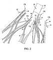
- a second, adjacent proximal apex 22b comprises an end region 40 having an integral barb 42 formed therein, as shown in FIGS. 1 to 2 .
- the second proximal apex 22b is not configured to be restrained using a trigger wire, as explained and shown in FIG. 2 below.
- the stent 20 may comprise one or more barbs 42 disposed in at least one of the end regions 40 of the second proximal apices 22b.
- the barbs 42 may be formed by laser cutting a desired barb shape into the end regions 40. A slit 41 therefore is formed into each end region 40 after the desired barb shape is formed, as shown in FIGS. 1 to 2 .
- a main body of the barb 42 may be bent in a radially outward direction with respect to the end region 40.
- the angle may comprise any acute angle, or alternatively may be substantially orthogonal or obtuse.
- the barbs 42 may be sharpened, for example, by grinding the tip of the barb, to facilitate engagement at a target tissue site.
- the stent 20 may comprise at least one strut segment disposed between the proximal and distal apices.
- multiple angled strut segments may be disposed between a first proximal apex 22a and a corresponding distal apex 62a, and an identical set of angled strut segments may be disposed between an adjacent, second proximal apex 22b and a corresponding distal apex 62b.
- the first proximal apex 22a extends distally and splits into first and second angled strut segments 57 and 58, respectively, thereby forming a proximal vertex 39, as shown in FIG. 1 .
- first and second angled strut segments 57 and 58 may be compressed such that they are substantially parallel to one another.
- the first and second angled strut segments 57 and 58 are disposed an angle relative to a longitudinal axis L of the stent 20.
- the first and second angled strut segments 57 and 58 may be disposed at an angle of about 20-60 degrees relative to the longitudinal axis L of the stent 20, as depicted in FIG. 1 .
- each distal apex 62a may extend in a proximal direction and splits into first and second angled strut segments 67 and 68, respectively, thereby forming a distal vertex 69.
- the first angled strut segments 57 and 67 of the proximal and distal apices 22a and 62a, respectively, may meet with the second angled strut segments 58 and 68 of the adjacent proximal and distal apices 22b and 62b, respectively, thereby forming a transition region 50.
- the stent 20 may be formed into a continuous, generally cylindrical shape, as shown in FIG. 1 .
- Expansion of the stent 20 is at least partly provided by the angled strut segments 57, 58, 67 and 68, which may be substantially parallel to one another in a compressed state, but may tend to bow outward away from one another in the expanded state shown in FIG. 1 .
- the stent 20 may be formed from any suitable material, and preferably a laser-cut Nitinol cannula. If manufactured from Nitinol, the stent 20 may assume the expanded state shown in FIG. 1 upon removal of a delivery sheath.
- Each transition region 50 may be oriented in a direction that is substantially parallel to the longitudinal axis L of the stent 20, as shown in FIG. 1 . Further, each transition region 50 may comprise a larger surface area relative to the angled segments, since the transition regions are composed substantially of multiple different angled segments 57, 58, 67 and 68 meeting up at a central location.
- the stent 20 may comprise at least one barb 52 disposed in at least one of the transition regions 50.
- the barb 52 may be formed integrally, as part of the strut, or may comprise an external barb that is adhered to a surface of the transition regions 50.
- multiple integral barbs 52 are provided.
- the barbs 52 may be formed by laser cutting a desired barb shape into the transition regions 50. In this manner, the barbs are monolithic with the transition region 50. A slit 51 therefore is formed into the transition region 50 after the desired barb shape is formed, as shown in FIG. 1 .
- transition regions 50 may comprise an increased surface area relative to other regions of the stent 20, it may be easier to perforate portions of the transition regions 50 without adversely affecting the structural integrity of the stent.
- a main body of the barb 52 may be bent in an outward direction at any angle with respect to the transition region 50 and optionally may be sharpened to facilitate engagement at a target tissue site.
- Each of distal apices 62a and 62b may comprise an end region 60 having a bore 61 formed therein, as shown in FIG. 1 .
- the distal end 24 of the stent 20 may be coupled to a proximal end of graft material (not shown).
- the distal apices 62a and 62b may be coupled to the graft material, for example, using one or more sutures that are looped through the graft material and the bores 61 of the stent 20. In this manner, the stent 20 may be used as an attachment stent for endovascular graft fixation.
- the graft material may overlap with an aneurysm to seal off fluid flow into the aneurysm, while the proximal end 22 of the stent 20 may extend in a proximal direction away from the graft material, for example to engage a healthy portion of a vessel wall away from a diseased portion of the aneurysm.
- the stent 20 has a reduced diameter delivery state so that it may be advanced to a target location within a vessel or duct.
- the stent 20 also has an expanded deployed state to apply a radially outward force upon at least a portion of a vessel or duct, e.g., to maintain patency within a passageway, or to hold open the lumen of a graft. In the expanded state, fluid flow is allowed through a central lumen of the stent 20.
- the struts of the stent 20 may comprise a substantially flat wire profile or may comprise a rounded profile. As best seen in FIG. 2 , the struts of the stent 20 generally comprise a flat wire profile.
- the stent 20 may be manufactured from a super-elastic material.
- the super-elastic material may comprise a shape-memory alloy, such as a nickel titanium alloy (Nitinol).
- Nitinol nickel titanium alloy
- the stent 20 may be heat-set into the desired expanded state, whereby the stent 20 can assume a relaxed configuration in which it assumes the preconfigured first expanded inner diameter upon application of a certain cold or hot medium.
- the stent 20 may be made from other metals and alloys that allow the stent 20 to return to its original, expanded configuration upon deployment, without inducing a permanent strain on the material due to compression.
- the stent 20 may comprise other materials such as stainless steel, cobalt-chrome alloys, amorphous metals, tantalum, platinum, gold and titanium.
- the stent 20 also may be made from non-metallic materials, such as thermoplastics and other polymers.
- the stent 20 may be delivered to a target site in a compressed configuration using a pushing member 80 and a plurality of trigger wires 84.
- the exemplary pushing member 80 comprises a main body 81 and a tapered region 82, which is disposed proximal to the main body 81.
- the tapered region 82 may subsequently transition into a smaller diameter at a proximal location, such that the relatively small diameter proximal region allows for atraumatic access and delivery.
- the plurality of trigger wires 84 may be disposed within the confines of the main body 81, and may span the length of the pushing member 80.
- the trigger wires 84 also may be activated by manipulating one or more handles, with optional locking features, to control deployment of the proximal end 22 of the stent 20.
- a single trigger wire 84 may be looped through the bore 31 of selected ones of the first proximal apices 22a to restrain the stent 20 during delivery. Trigger wires are not coupled to the second proximal apices 22b, which comprise the barbs 42. In the embodiment shown, the trigger wires 84 are only disposed through alternating proximal apices, as seen in FIG. 2 . By restraining selected ones of the first proximal apices, such as each first proximal apex 22a, the adjacent second proximal apices 22b also may be indirectly pulled in a radially inward direction during delivery.
- the number of trigger wires may be reduced.
- the barbs 42 are only disposed on every other apex, barb entanglement may be reduced or eliminated, as depicted in FIG. 2 .
- the trigger wires 84 are only disposed through the bores 31 of the first proximal apices 22a, as opposed to being disposed through the vertices 39. Therefore, the trigger wires 84 may be less likely to become damaged during compression of the stent 20. Further, the stent struts themselves are less likely to become damaged since the trigger wires 84 are isolated within the bores 31 of the first proximal apices 22a.
- stent 120 also may be manufactured from a continuous cylinder into which a pattern may be cut by a laser or by chemical etching to produce slits in the wall of the cylinder. The resulting structure may thereafter be heat set to give it a desired final configuration.
- the preferred final configuration includes a shape having a series of proximal apices and a series of distal apices, as generally shown in FIG. 3 .
- the proximal end 122 of the stent 120 may comprise multiple adjacent proximal apices 122a and 122b, while the distal end 124 of the stent 20 may comprise multiple adjacent distal apices 162a and 162b, as shown in FIG. 3 .
- One or more pairs of adjacent, proximal apices 122a and 122b may comprise different features.
- a first proximal apex 122a may comprise an end region 130 having a first bore 131 formed therein, wherein the first bore 131 is configured to receive a trigger wire 184, as shown in FIGS. 5 to 6 .
- a second, adjacent proximal apex 122b comprises an end region 140 having an integral barb 142 formed therein, as shown in FIGS. 3 to 6 .
- the second proximal apex 122b also includes a second bore 145 formed therein, as best seen in FIG. 4 , which is configured to receive the same trigger wire 184 as the adjacent first proximal apex 122a, as explained and shown with respect to FIGS. 5 to 6 .
- Each of the second proximal apices 122b may comprise first and second regions 147 and 148, as shown in FIG. 4 .
- a single barb 142 may be disposed in each of the second proximal apices 122b generally in the first region 147, while the second bore 145 may be disposed generally in the second region 148, as shown in FIG. 4 .
- the barbs 142 may be formed by laser cutting a desired barb shape into the end regions 140, thereby forming a slit 141, as generally explained with respect to the stent 20 hereinabove. Once the desired barb shape is cut, a main body of the barb 142 may be bent in a radially outward direction and optionally may be sharpened, as generally set forth above.
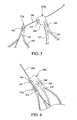
- the second proximal apices 122b further may comprise a recessed portion 149 formed at a location distal to the second bore 145, as best seen in FIG. 4 .
- the first proximal apex 122a is configured to be pulled towards the second proximal apex 122b and may become nested within the recessed portion 149 of the second proximal apex 122b when a trigger wire is disposed through the first and second bores 131 and 145.
- the first bores 131 of the first proximal apices 122a may be disposed slightly distal to the second bores 145 of an adjacent, second proximal apex 122b. Further, a first longitudinal distance L 1 between a distal edge h 0 of the stent 120 and a proximal edge h 1 of each proximal apex 122a may be less than a second longitudinal distance L 2 between the distal edge h 0 of the stent and a distal edge h 2 of each recessed portion 149, as shown in FIG. 3 . This length differentiation may facilitate nesting of the first proximal apices 122a within the recessed portions 149 of the second proximal apices 122b during delivery of the stent, as explained further below with respect to FIGS. 5 to 6 .
- the stent 120 may comprise at least one strut segment disposed between the proximal and distal apices.
- the proximal and distal apices are not directly aligned with one another.
- a first angled segment 157 may be disposed between a proximal apex 122a and a corresponding distal apex 162a
- a second angled segment 158 may be disposed between the same proximal apex 122a and an adjacent distal apex 162b.
- each proximal apex 122a and 122b extends distally and splits into the first and second angled strut segments 157 and 158, respectively, thereby forming a proximal vertex 139.
- each distal apex 162a and 162b extends proximally and splits into the first and second angled strut segments 157 and 158, respectively, thereby forming a distal vertex 169.
- the stent 120 may be formed into a continuous, generally cylindrical shape, as shown in FIG. 3 .
- the first and second angled strut segments 157 and 158 may be compressed such that they are substantially parallel to one another.
- the first and second angled strut segments 157 and 158 may be disposed at an angle relative to a longitudinal axis L of the stent 120, as shown in FIG. 3 .
- the first and second angled strut segments 157 and 158 may be disposed at an angle of about 20-60 degrees relative to the longitudinal axis L of the stent 120.
- Expansion of the stent 120 is at least partly provided by the angled strut segments 157 and 158, which may be substantially parallel to one another in a compressed state, but may tend to bow outward away from one another in the expanded state shown in FIG. 3 .
- the stent 120 may be formed from any suitable material, and preferably a nickel-titanium alloy, so that it may assume the expanded state shown in FIG. 3 upon removal of a delivery sheath.
- the first and second angled strut segments 157 and 158 meet with one another distally to form a distal transition region 150, which effectively is the same as the distal end region 160 of the stent 120.
- Each end region 160 may be oriented in a direction that is substantially parallel to the longitudinal axis L of the stent 120, as shown in FIG. 3 . Further, each end region 160 may comprise a larger surface area relative to the angled segments, since the end regions 160 are composed substantially of multiple different angled segments 157 and 158 meeting up together.
- At least one distal barb 152 may be formed integrally by laser cutting a desired barb shape, thereby forming a slit 151 into the end region 160, as shown in FIG. 3 .
- end regions 160 may comprise an increased surface area relative to other regions of the stent 120, it may be easier to perforate portions of the end regions 160 without adversely affecting the structural integrity of the stent.
- a suture bore 161 may be formed in the end regions 160 of each of the distal apices 162a and 162b, as shown in FIG. 3 .
- the distal end 124 of the stent 120 may be coupled to a proximal end of graft material (not shown) by looping the suture through the bore 161 and the graft material, as generally explained above with respect to the embodiment of FIGS. 1-2 .
- the stent 120 may be delivered to a target site in a compressed configuration using a pushing member, such as pushing member 80 of FIG. 2 , and a plurality of trigger wires.
- a trigger wire 184 may be looped through the first bore 131 of each first proximal apex 122a, and further looped through the second bore of an adjacent, second proximal apex 122b. Therefore, each individual trigger wire may restrain two separate, adjacent proximal apices during delivery.
- the adjacent first and second proximal apices 122a and 122b may be pulled closer together.
- each proximal apex 122a may become nested substantially within the recessed portion 149 distal to the second region 148 of the proximal apex 122b, as shown in FIG. 6 .
- the first bore 131 may be positioned distal to the second bore 145, such that the first and second bores 131 and 145 are disposed substantially in longitudinal alignment with one another when the single trigger wire 184 is disposed through the first and second bores during delivery of the stent.
- one single trigger wire may be used to restrain two separate, adjacent apices of the stent 120.
- the trigger wires 184 are only disposed through the bores 131 and 145, but not disposed around the vertices 139, and therefore the trigger wires may be less likely to become damaged during compression of the stent 120.
- the stent struts themselves are less likely to become damaged since the trigger wires 184 are isolated within the bores 131 and 145.
- one or more of the distal apices 162a and 162b optionally may comprise an imaging bore 190, which may be disposed between the suture bore 161 and the barb slit 151.
- the imaging bore 190 may receive any suitable radiopaque marker, such as a gold marker.
- the imaging bores 190 and associated radiopaque markers are provided on alternating distal apices, for example only distal apices 162a.
- the imaging bores 190 may be disposed on each distal apex 162a and 162b, or disposed on every third or fourth apex around the perimeter of the stent.
- the imaging bores 190 may be beveled or, alternatively, may be substantially orthogonal to the strut of the end region 160.
- the imaging bores 190 may be aligned with the distal edge of a graft material, for example, when the stent 120 is used for endovascular graft fixation. More specifically, the suture bore 161 overlaps with a proximal region of the graft material, thereby allowing a suture to couple the stent 120 to the graft material with some desired degree of overlap. The proximal edge of the graft material therefore may be aligned with the imaging bores 190.
- a physician may know exactly where the proximal edge of the graft material is being placed because he or she can view the position of the radiopaque markers in the imaging bores 190. Therefore, the chances of inadvertently overlapping the graft material with a branch vessel, or another undesired location, may be reduced.
Landscapes
- Health & Medical Sciences (AREA)
- Engineering & Computer Science (AREA)
- Biomedical Technology (AREA)
- Heart & Thoracic Surgery (AREA)
- Life Sciences & Earth Sciences (AREA)
- Cardiology (AREA)
- Oral & Maxillofacial Surgery (AREA)
- Transplantation (AREA)
- Veterinary Medicine (AREA)
- Vascular Medicine (AREA)
- Public Health (AREA)
- Animal Behavior & Ethology (AREA)
- General Health & Medical Sciences (AREA)
- Optics & Photonics (AREA)
- Physics & Mathematics (AREA)
- Prostheses (AREA)
- Media Introduction/Drainage Providing Device (AREA)
Claims (20)
- Endoprothèse (20 ; 120) destinée à l'utilisation dans une procédure médicale, l'endoprothèse comprenant :une série de sommets proximaux (22a, 22b ; 122a, 122b) disposés à une extrémité proximale (22) de l'endoprothèse ;une série de sommets distaux (62a, 62b ; 162a, 162b) disposés à une extrémité distale (24) de l'endoprothèse ; etau moins un segment d'entretoise (57, 58, 67, 68 ; 157, 158) disposé entre un sommet proximal et un sommet distal, le segment d'entretoise permettant l'expansion de l'endoprothèse d'un état comprimé à un état déployé,la série de sommets proximaux comprenant des premiers sommets proximaux (22a ; 122a) en alternance avec des deuxièmes sommets proximaux (22b ; 122b), au moins une paire de sommets proximaux adjacents comprenant des caractéristiques différentes ;dans laquelle :a) chacun des premiers sommets proximaux (22a ; 122a) comporte une région d'extrémité (30 ; 130) ayant un alésage (31 ; 131) et chacun des deuxièmes sommets proximaux (22b ; 122b) comprend au moins une barbe (42 ; 142) destinée à s'engager avec des tissus, les barbes n'étant pas disposées sur chaque sommet proximal de l'endoprothèse ; et/oub) chacun des premiers sommets proximaux (122a) comporte une région d'extrémité (130) pourvue d'un premier alésage (131) et dans laquelle chacun des deuxièmes sommets proximaux (122b) comporte un deuxième alésage (145) et au moins l'un des premiers sommets proximaux est simultanément retenu par un deuxième sommet proximal adjacent au cours de la mise en place de l'endoprothèse ; et/ouc) chacun des premiers sommets proximaux (122a) comporte une région d'extrémité ayant un premier alésage (131), et chacun des deuxièmes sommets proximaux (122b) comporte une première région (147) et une deuxième région (148), au moins une barbe intégrale (142) étant formée dans la première région et un deuxième alésage (145) étant formé dans la deuxième région, les barbes n'étant pas disposées sur chaque sommet proximal de l'endoprothèse, et dans laquelle chacun des deuxièmes sommets proximaux comporte une portion en retrait (149) formée dans le deuxième sommet proximal en un emplacement distal par rapport au deuxième alésage, au moins l'un des premiers sommets proximaux étant emboîté à l'intérieur de la portion en retrait d'un deuxième sommet proximal adjacent au cours de la mise en place de l'endoprothèse.
- Endoprothèse (20 ; 120) selon la revendication 1, dans laquelle chacun des premiers sommets proximaux comporte une région d'extrémité (30) ayant un alésage (31), et chacun des deuxièmes sommets proximaux (22b) comprend au moins une barbe (42) pour s'engager avec des tissus.
- Endoprothèse (20 ; 120) selon la revendication 2, dans laquelle chacun des premiers sommets proximaux (22a ; 122a) est retenu directement par une pluralité de fils de déclenchement (84 ; 184), de telle sorte qu'un sommet proximal sur deux de l'endoprothèse soit directement retenu par un fil de déclenchement.
- Endoprothèse (20 ; 120) selon la revendication 2 ou 3, dans laquelle la barbe (42) du deuxième sommet proximal (22b ; 122b) est formée intégralement dans une région d'extrémité (40 ; 140) du deuxième sommet proximal.
- Endoprothèse (20 ; 120) selon la revendication 2, 3 ou 4, dans laquelle des segments d'entretoises inclinés multiples (57, 58, 67, 68 ; 157, 158) sont disposés entre chaque sommet proximal (22a, 22b ; 122a, 122b) et chaque sommet distal (62a, 62b ; 162a, 162b).
- Endoprothèse (20) selon la revendication 5, dans laquelle des segments d'entretoises inclinés multiples (57, 58, 67, 68) sont réunis au niveau d'une région de transition (50) entre les sommets proximaux (22a, 22b) et les sommets distaux (62a, 62b), et dans laquelle au moins une barbe (52) est formée intégralement dans une surface de la région de transition.
- Endoprothèse (20 ; 120) selon l'une quelconque des revendications 2 à 6, dans laquelle chacun des sommets distaux (62a, 62b ; 162a, 162b) comporte une région d'extrémité (60 ; 160) pourvue d'un alésage (61 ; 161) apte à recevoir une suture pour accoupler une extrémité distale (24 ; 124) de l'endoprothèse à un matériau de greffe.
- Endoprothèse (20 ; 120) selon l'une quelconque des revendications 2 à 7, comportant deux ou plus des caractéristiques suivantes :chacun des premiers sommets proximaux (22a ; 122a) est retenu directement par une pluralité de fils de déclenchement (84) ;la barbe (42 ; 142) du deuxième sommet proximal (22b ; 122b) est formée intégralement dans une région d'extrémité (30 ; 130) du deuxième sommet proximal ;des segments d'entretoises inclinés multiples(57, 58 ; 67, 68) sont disposés entre chaque sommet proximal (22a) et chaque sommet distal (62b) ; et chacun des sommets distaux (62a, 62b ; 162a, 162b) comporte une région d'extrémité (60 ; 160) pourvue d'un alésage (61 ; 161) pour recevoir une suture pour accoupler une extrémité distale (24 ; 124) de l'endoprothèse à un matériau de greffe.
- Endoprothèse (120) selon la revendication 1, dans laquelle chacun des premiers sommets proximaux (122a) comporte une région d'extrémité (130) pourvue d'un premier alésage (131), et dans laquelle chacun des deuxièmes sommets proximaux (122b) comporte un deuxième alésage (145), et
dans laquelle au moins l'un des premiers sommets proximaux est simultanément retenu par un deuxième sommet proximal adjacent au cours de la mise en place de l'endoprothèse. - Endoprothèse (120) selon la revendication 9, dans laquelle le deuxième sommet proximal (122b) comporte une première région (147) et une deuxième région (148), dans laquelle au moins une barbe intégrale (142) est formée dans la première région, et dans laquelle le deuxième alésage (145) est formé dans la deuxième région.
- Endoprothèse (120) selon la revendication 10, comportant une portion en retrait (149) formée dans le deuxième sommet proximal (122b) en un emplacement distal par rapport au deuxième alésage (145), le premier sommet proximal (122a) étant configuré pour être tiré vers le deuxième sommet proximal afin de devenir emboîté à l'intérieur de la portion en retrait du deuxième sommet proximal.
- Endoprothèse (120) selon l'une quelconque des revendications 9 à 11, dans laquelle le premier alésage (131) est disposé distalement par rapport au deuxième alésage (145), et dans laquelle le premier alésage et le deuxième alésage sont disposés substantiellement en alignement longitudinal l'un avec l'autre lorsqu'un seul fil de déclenchement (184) est disposé à travers le premier alésage et le deuxième alésage au cours de la mise en place de l'endoprothèse.
- Endoprothèse (120) selon l'une quelconque des revendications 9 à 12, comportant deux ou plus des caractéristiques suivantes :le deuxième sommet proximal (122b) comporte une première région (147) et une deuxième région (148) et au moins une barbe intégrale (142) est formée dans la première région et le deuxième alésage (145) est formé dans la deuxième région ;une portion en retrait (149) est formée dans le deuxième sommet proximal en un emplacement distal par rapport au deuxième alésage et le premier sommet proximal (122a) est configuré pour être tiré vers le deuxième sommet proximal de manière à devenir emboîté à l'intérieur de la portion en retrait du deuxième sommet proximal ;le premier alésage (131) est disposé distalement par rapport au deuxième alésage, et le premier alésage et le deuxième alésage sont disposés substantiellement en alignement longitudinal l'un avec l'autre lorsqu'un seul fil de déclenchement (184) est disposé à travers le premier alésage et le deuxième alésage au cours de la mise en place de l'endoprothèse ;chacun des sommets distaux (162a, 162b) comporte une région d'extrémité (160) pourvue d'un alésage de suture (161) pour recevoir une suture de manière à accoupler une extrémité distale (124) de l'endoprothèse à un matériau de greffe ; etchacun des sommets distaux comporte un alésage d'imagerie (190) pouvant fonctionner de manière à recevoir un marqueur radio-opaque, l'alésage d'imagerie étant disposé proximalement par rapport à l'alésage de suture et l'alésage d'imagerie étant apte à être aligné avec le bord proximal du matériau de greffe.
- Endoprothèse (120) selon la revendication 1, dans laquelle chacun des premiers sommets proximaux (122a) comporte une région d'extrémité ayant un premier alésage (131),
dans laquelle chacun des deuxièmes sommets proximaux (122b) comporte une première région (147) et une deuxième région (148), dans laquelle au moins une barbe intégrale (142) est formée dans la première région et un deuxième alésage (145) est formé dans la deuxième région, dans laquelle des barbes ne sont pas disposées sur chaque sommet proximal de l'endoprothèse, et dans laquelle chacun des deuxièmes sommets proximaux comporte une portion en retrait (149) formée dans le deuxième sommet proximal en un emplacement distal par rapport au deuxième alésage, et
dans laquelle au moins l'un des premiers sommets proximaux est emboîté à l'intérieur de la portion en retrait d'un deuxième sommet proximal adjacent au cours de la mise en place de l'endoprothèse. - Endoprothèse (120) selon la revendication 11 ou 14, dans laquelle une première distance longitudinale (L1) entre un bord proximal du premier sommet proximal (122a) et un bord distal de l'endoprothèse est inférieure à une deuxième distance longitudinale (L2) entre la portion en retrait (149) du deuxième sommet proximal (122b) et le bord distal de l'endoprothèse.
- Endoprothèse (120) selon l'une quelconque des revendications 9 à 12, 14 ou 15, dans laquelle chacun des sommets distaux (162a, 162b) comporte un alésage de suture (161) pour recevoir une suture pour accoupler une extrémité distale de l'endoprothèse à un matériau de greffe.
- Endoprothèse selon la revendication 16, dans laquelle chacun des sommets distaux (162a, 162b) comporte un alésage d'imagerie (190) pour recevoir un marqueur radio-opaque, dans laquelle l'alésage d'imagerie est disposé proximalement par rapport à l'alésage de suture (161), et l'alésage d'imagerie est prévu pour être aligné avec le bord proximal du matériau de greffe.
- Endoprothèse (120) selon la revendication 16 ou 17, comportant au moins une barbe (152) formée intégralement dans la région d'extrémité (160) de chacun des sommets distaux (162a, 162b).
- Dispositif médical implantable comportant une endoprothèse (20 ; 120) selon l'une quelconque des revendications précédentes.
- Dispositif d'introduction sur lequel est montée une endoprothèse (20 ; 120) selon l'une quelconque des revendications 1 à 18 ou un dispositif médical implantable selon la revendication 19.
Applications Claiming Priority (2)
| Application Number | Priority Date | Filing Date | Title |
|---|---|---|---|
| US2719208P | 2008-02-08 | 2008-02-08 | |
| PCT/US2009/000747 WO2009099632A2 (fr) | 2008-02-08 | 2009-02-06 | Modèles d’endoprothèses à utiliser avec un ou plusieurs fils de déclenchement |
Publications (2)
| Publication Number | Publication Date |
|---|---|
| EP2237749A2 EP2237749A2 (fr) | 2010-10-13 |
| EP2237749B1 true EP2237749B1 (fr) | 2015-04-08 |
Family
ID=40848530
Family Applications (1)
| Application Number | Title | Priority Date | Filing Date |
|---|---|---|---|
| EP09708866.0A Active EP2237749B1 (fr) | 2008-02-08 | 2009-02-06 | Modèles d endoprothèses à utiliser avec un ou plusieurs fils de déclenchement |
Country Status (6)
| Country | Link |
|---|---|
| US (3) | US8163007B2 (fr) |
| EP (1) | EP2237749B1 (fr) |
| JP (1) | JP5559063B2 (fr) |
| AU (1) | AU2009210732B2 (fr) |
| CA (1) | CA2711849C (fr) |
| WO (1) | WO2009099632A2 (fr) |
Families Citing this family (56)
| Publication number | Priority date | Publication date | Assignee | Title |
|---|---|---|---|---|
| JP4812316B2 (ja) * | 2005-03-16 | 2011-11-09 | イビデン株式会社 | ハニカム構造体 |
| US7914569B2 (en) * | 2005-05-13 | 2011-03-29 | Medtronics Corevalve Llc | Heart valve prosthesis and methods of manufacture and use |
| US8163007B2 (en) | 2008-02-08 | 2012-04-24 | Cook Medical Technologies Llc | Stent designs for use with one or more trigger wires |
| US7655037B2 (en) * | 2008-04-17 | 2010-02-02 | Cordis Corporation | Combination barb restraint and stent attachment deployment mechanism |
| US8394139B2 (en) * | 2008-08-29 | 2013-03-12 | Cook Medical Technologies Llc | Barbed anchors for wire stent |
| GB2464977B (en) | 2008-10-31 | 2010-11-03 | William Cook Europe As | Introducer for deploying a stent graft in a curved lumen and stent graft therefor |
| US11376114B2 (en) | 2008-10-31 | 2022-07-05 | Cook Medical Technologies Llc | Introducer for deploying a stent graft in a curved lumen and stent graft therefor |
| US8523932B2 (en) | 2010-05-24 | 2013-09-03 | Cook Medical Technologies Llc | Variable diameter trigger wire |
| USD653341S1 (en) * | 2010-09-20 | 2012-01-31 | St. Jude Medical, Inc. | Surgical stent |
| USD654169S1 (en) * | 2010-09-20 | 2012-02-14 | St. Jude Medical Inc. | Forked ends |
| USD652927S1 (en) * | 2010-09-20 | 2012-01-24 | St. Jude Medical, Inc. | Surgical stent |
| USD684692S1 (en) * | 2010-09-20 | 2013-06-18 | St. Jude Medical, Inc. | Forked ends |
| USD652926S1 (en) * | 2010-09-20 | 2012-01-24 | St. Jude Medical, Inc. | Forked end |
| USD660433S1 (en) * | 2010-09-20 | 2012-05-22 | St. Jude Medical, Inc. | Surgical stent assembly |
| USD654170S1 (en) * | 2010-09-20 | 2012-02-14 | St. Jude Medical, Inc. | Stent connections |
| USD653342S1 (en) * | 2010-09-20 | 2012-01-31 | St. Jude Medical, Inc. | Stent connections |
| USD660432S1 (en) * | 2010-09-20 | 2012-05-22 | St. Jude Medical, Inc. | Commissure point |
| USD660967S1 (en) * | 2010-09-20 | 2012-05-29 | St. Jude Medical, Inc. | Surgical stent |
| USD653343S1 (en) | 2010-09-20 | 2012-01-31 | St. Jude Medical, Inc. | Surgical cuff |
| USD648854S1 (en) * | 2010-09-20 | 2011-11-15 | St. Jude Medical, Inc. | Commissure points |
| US20130226282A1 (en) * | 2010-10-29 | 2013-08-29 | Medisourceplus Co., Ltd. | Stent wires, and method for manufacturing such stent wires and stents |
| BR112013023320A2 (pt) * | 2011-03-29 | 2016-12-13 | Terumo Corp | stent e sistema de stent |
| US8840659B2 (en) * | 2011-04-28 | 2014-09-23 | Cook Medical Technologies Llc | Stent and stent-graft designs |
| US8920482B2 (en) | 2011-06-30 | 2014-12-30 | Cook Medical Technologies Llc | Stent delivery system |
| US8728148B2 (en) | 2011-11-09 | 2014-05-20 | Cook Medical Technologies Llc | Diameter reducing tie arrangement for endoluminal prosthesis |
| US9220620B2 (en) | 2011-11-22 | 2015-12-29 | Cook Medical Technologies Llc | Endoluminal prosthesis introducer |
| EP2604232B1 (fr) | 2011-12-14 | 2021-02-24 | Cook Medical Technologies LLC | Fil de déclenchement circonférentiel pour déployer une prothèse endoluminale |
| US9629737B2 (en) | 2011-12-23 | 2017-04-25 | Cook Medical Technologies Llc | Delivery system for staged stent release |
| GB2512775A (en) * | 2011-12-29 | 2014-10-08 | Beijing Percutek Therapeutics Co Ltd | Aorta covered stent |
| US9393140B2 (en) | 2012-04-27 | 2016-07-19 | Medtronic Vascular, Inc. | Reconfigurable stent-graft delivery system and method of use |
| US8968384B2 (en) | 2012-04-27 | 2015-03-03 | Medtronic Vascular, Inc. | Circumferentially constraining sutures for a stent-graft |
| US9452069B2 (en) | 2012-04-27 | 2016-09-27 | Medtronic Vascular, Inc. | Reconfigurable stent-graft delivery system and method of use |
| US10098767B2 (en) | 2012-04-27 | 2018-10-16 | Medtronic Vascular, Inc. | Reconfigurable stent-graft delivery system and method of use |
| US9737394B2 (en) | 2012-04-27 | 2017-08-22 | Medtronic Vascular, Inc. | Stent-graft prosthesis for placement in the abdominal aorta |
| US9750626B2 (en) * | 2012-10-31 | 2017-09-05 | Cook Medical Technologies Llc | Apparatus and methods for improved stent deployment |
| US9855129B2 (en) | 2012-10-31 | 2018-01-02 | Cook Medical Technologies Llc | Multi-level suture attachments for coupling a stent to graft material |
| US9622893B2 (en) | 2012-12-20 | 2017-04-18 | Cook Medical Technologies Llc | Apparatus and method for improved deployment of endovascular grafts |
| US10039657B2 (en) * | 2012-12-21 | 2018-08-07 | CARDINAL HEALTH SWITZERLAND 515 GmbH | Cannulation guiding device for bifurcated stent and method of use |
| US9675439B2 (en) | 2012-12-21 | 2017-06-13 | Cook Medical Technologies Llc | Stent designs for reduced infolding of graft material |
| US10350096B2 (en) | 2012-12-26 | 2019-07-16 | Cook Medical Technologies Llc | Expandable stent-graft system having diameter reducing connectors |
| US9351860B2 (en) | 2013-03-14 | 2016-05-31 | Cook Medical Technologies Llc | Loading tool for capturing stent points |
| WO2014189977A1 (fr) | 2013-05-20 | 2014-11-27 | Edwards Lifesciences Corporation | Appareil de pose de valvule cardiaque prothétique |
| USD730520S1 (en) * | 2013-09-04 | 2015-05-26 | St. Jude Medical, Cardiology Division, Inc. | Stent with commissure attachments |
| USD730521S1 (en) * | 2013-09-04 | 2015-05-26 | St. Jude Medical, Cardiology Division, Inc. | Stent with commissure attachments |
| US11123205B2 (en) * | 2013-09-24 | 2021-09-21 | Trivascular, Inc. | Tandem modular endograft |
| WO2015127283A1 (fr) * | 2014-02-21 | 2015-08-27 | Cardiaq Valve Technologies, Inc. | Dispositif d'acheminement pour le déploiement maîtrisé d'une de valvule de substitution |
| US9855155B2 (en) * | 2014-06-26 | 2018-01-02 | Cardinal Health Switzeerland 515 Gmbh | Endoprosthesis anchoring and sealing |
| CN104546242B (zh) * | 2014-12-02 | 2017-01-25 | 先健科技(深圳)有限公司 | 植入体的输送装置及植入医疗器械 |
| EP3040056B1 (fr) | 2014-12-29 | 2019-09-11 | Cook Medical Technologies LLC | Système de déploiement de prothèse |
| US10583007B2 (en) | 2015-12-02 | 2020-03-10 | Edwards Lifesciences Corporation | Suture deployment of prosthetic heart valve |
| WO2017196909A1 (fr) * | 2016-05-12 | 2017-11-16 | St. Jude Medical, Cardiology Division, Inc. | Remplacement de valvule mitrale cardiaque |
| US10709541B2 (en) | 2017-04-28 | 2020-07-14 | Cook Medical Technologies Llc | Systems and methods for adjusting the diameter of an endoluminal prosthesis and an endoluminal prosthesis configured for the same |
| US20210346153A1 (en) * | 2020-05-11 | 2021-11-11 | St. Jude Medical, Cardiology Division, Inc. | Transcatheter Mitral Valve Fixation Concepts |
| GB2605559B (en) | 2021-01-07 | 2023-04-05 | Cook Medical Technologies Llc | Stent graft |
| WO2024064905A1 (fr) * | 2022-09-23 | 2024-03-28 | Rivermark Medical, Inc. | Stent intraluminal avec poignée pour le traitement de l'hyperplasie bénigne de la prostate |
| CN116549194B (zh) * | 2023-07-07 | 2024-03-01 | 浙江归创医疗科技有限公司 | 输送系统支架收束机构及腹主动脉覆膜支架输送系统 |
Family Cites Families (42)
| Publication number | Priority date | Publication date | Assignee | Title |
|---|---|---|---|---|
| US5669936A (en) * | 1983-12-09 | 1997-09-23 | Endovascular Technologies, Inc. | Endovascular grafting system and method for use therewith |
| US6221102B1 (en) * | 1983-12-09 | 2001-04-24 | Endovascular Technologies, Inc. | Intraluminal grafting system |
| US7166125B1 (en) * | 1988-03-09 | 2007-01-23 | Endovascular Technologies, Inc. | Intraluminal grafting system |
| US5628783A (en) * | 1991-04-11 | 1997-05-13 | Endovascular Technologies, Inc. | Bifurcated multicapsule intraluminal grafting system and method |
| US6682557B1 (en) * | 1991-04-11 | 2004-01-27 | Endovascular Technologies, Inc. | Bifurcated multicapsule intraluminal grafting system and method |
| CA2065634C (fr) * | 1991-04-11 | 1997-06-03 | Alec A. Piplani | Greffon endovasculaire ayant une bifurcation et appareil et methode servant a le deployer |
| FR2699809B1 (fr) * | 1992-12-28 | 1995-02-17 | Celsa Lg | Dispositif pouvant constituer sélectivement un filtre sanguin temporaire. |
| US5824044A (en) * | 1994-05-12 | 1998-10-20 | Endovascular Technologies, Inc. | Bifurcated multicapsule intraluminal grafting system |
| US5527355A (en) * | 1994-09-02 | 1996-06-18 | Ahn; Sam S. | Apparatus and method for performing aneurysm repair |
| US5843170A (en) * | 1994-09-02 | 1998-12-01 | Ahn; Sam Seunghae | Apparatus and method for performing aneurysm repair |
| US6814748B1 (en) * | 1995-06-07 | 2004-11-09 | Endovascular Technologies, Inc. | Intraluminal grafting system |
| US6030415A (en) * | 1997-01-29 | 2000-02-29 | Endovascular Technologies, Inc. | Bell-bottom modular stent-graft |
| US6849087B1 (en) * | 1999-10-06 | 2005-02-01 | Timothy A. M. Chuter | Device and method for staged implantation of a graft for vascular repair |
| US6808534B1 (en) * | 2000-02-16 | 2004-10-26 | Endovascular Technologies, Inc. | Collapsible jacket guard |
| US6517573B1 (en) * | 2000-04-11 | 2003-02-11 | Endovascular Technologies, Inc. | Hook for attaching to a corporeal lumen and method of manufacturing |
| US6361556B1 (en) * | 2000-04-27 | 2002-03-26 | Endovascular Tech Inc | System and method for endovascular aneurysm repair in conjuction with vascular stabilization |
| US7666221B2 (en) * | 2000-05-01 | 2010-02-23 | Endovascular Technologies, Inc. | Lock modular graft component junctions |
| US6454796B1 (en) * | 2000-05-05 | 2002-09-24 | Endovascular Technologies, Inc. | Vascular graft |
| US7708771B2 (en) * | 2002-02-26 | 2010-05-04 | Endovascular Technologies, Inc. | Endovascular graft device and methods for attaching components thereof |
| EP1569582B1 (fr) * | 2002-12-02 | 2017-05-31 | GI Dynamics, Inc. | Manchon contre l'obesite |
| WO2004078065A2 (fr) * | 2003-03-03 | 2004-09-16 | Sinus Rhythm Technologies, Inc. | Implant de bloc electrique |
| US6984244B2 (en) * | 2003-03-27 | 2006-01-10 | Endovascular Technologies, Inc. | Delivery system for endoluminal implant |
| US20040243221A1 (en) * | 2003-05-27 | 2004-12-02 | Fawzi Natalie V. | Endovascular graft including substructure for positioning and sealing within vasculature |
| US7651519B2 (en) * | 2003-09-16 | 2010-01-26 | Cook Incorporated | Prosthesis deployment system |
| EP1684668B1 (fr) * | 2003-11-08 | 2018-10-17 | Cook Medical Technologies LLC | Endoprotheses d'aortes et de branches vasculaires et systeme |
| WO2005060882A1 (fr) * | 2003-12-09 | 2005-07-07 | Gi Dynamics, Inc. | Dispositif s'ancrant dans le tube digestif et son procede d'ancrage |
| US8182528B2 (en) * | 2003-12-23 | 2012-05-22 | Sadra Medical, Inc. | Locking heart valve anchor |
| US8043354B2 (en) * | 2004-06-16 | 2011-10-25 | William A. Cook Australia Pty. Ltd. | Thoracic deployment device and stent graft |
| DE102004041259B4 (de) * | 2004-08-26 | 2008-03-06 | Osypka, Peter, Dr.-Ing. | Vorrichtung zum Aussteifen und Entlasten einer Gefäßaufweitung |
| EP1991168B1 (fr) * | 2006-02-16 | 2016-01-27 | Transcatheter Technologies GmbH | Remplacement d'une valvule cardiaque en une chirurgie mini-invasive |
| JP5042244B2 (ja) * | 2006-02-27 | 2012-10-03 | ウィリアム・エイ・クック・オーストラリア・プロプライエタリー・リミテッド | ステントグラフトの導入器とステントグラフトとの結合体 |
| US20100010622A1 (en) * | 2006-03-13 | 2010-01-14 | Abbott Laboratories | Hybrid segmented endoprosthesis |
| US8460362B2 (en) * | 2006-07-20 | 2013-06-11 | Orbusneich Medical, Inc. | Bioabsorbable polymeric medical device |
| JP5520432B2 (ja) | 2006-10-03 | 2014-06-11 | 古河電気工業株式会社 | 半導体トランジスタの製造方法 |
| DE202007005491U1 (de) | 2007-04-13 | 2007-06-14 | Jenavalve Technology Gmbh | Medizinische Vorrichtung zur Behandlung einer Aortenklappeninsuffizienz |
| US8092510B2 (en) * | 2007-07-25 | 2012-01-10 | Cook Medical Technologies Llc | Retention wire for self-expanding stent |
| US20090082845A1 (en) * | 2007-09-26 | 2009-03-26 | Boston Scientific Corporation | Alignment stent apparatus and method |
| US20090125096A1 (en) * | 2007-11-12 | 2009-05-14 | Medtronic Vascular, Inc. | Stent Graft With Pins |
| US7905915B2 (en) * | 2007-12-27 | 2011-03-15 | Cook Incorporated | Z-stent with incorporated barbs |
| US20090234429A1 (en) * | 2008-02-07 | 2009-09-17 | Lilip Lau | Self-restraining endoluminal prosthesis |
| US8163007B2 (en) * | 2008-02-08 | 2012-04-24 | Cook Medical Technologies Llc | Stent designs for use with one or more trigger wires |
| US8840659B2 (en) * | 2011-04-28 | 2014-09-23 | Cook Medical Technologies Llc | Stent and stent-graft designs |
-
2009
- 2009-02-02 US US12/364,162 patent/US8163007B2/en active Active
- 2009-02-06 JP JP2010545876A patent/JP5559063B2/ja active Active
- 2009-02-06 WO PCT/US2009/000747 patent/WO2009099632A2/fr active Application Filing
- 2009-02-06 AU AU2009210732A patent/AU2009210732B2/en active Active
- 2009-02-06 CA CA2711849A patent/CA2711849C/fr active Active
- 2009-02-06 EP EP09708866.0A patent/EP2237749B1/fr active Active
-
2012
- 2012-03-26 US US13/429,983 patent/US9833345B2/en active Active
-
2017
- 2017-11-16 US US15/814,952 patent/US10363154B2/en active Active
Also Published As
| Publication number | Publication date |
|---|---|
| JP5559063B2 (ja) | 2014-07-23 |
| US10363154B2 (en) | 2019-07-30 |
| CA2711849C (fr) | 2015-09-08 |
| WO2009099632A2 (fr) | 2009-08-13 |
| EP2237749A2 (fr) | 2010-10-13 |
| US20180071122A1 (en) | 2018-03-15 |
| JP2011510788A (ja) | 2011-04-07 |
| US8163007B2 (en) | 2012-04-24 |
| WO2009099632A3 (fr) | 2009-10-01 |
| AU2009210732B2 (en) | 2013-02-21 |
| US9833345B2 (en) | 2017-12-05 |
| US20120245676A1 (en) | 2012-09-27 |
| US20090204202A1 (en) | 2009-08-13 |
| AU2009210732A1 (en) | 2009-08-13 |
| CA2711849A1 (fr) | 2009-08-13 |
Similar Documents
| Publication | Publication Date | Title |
|---|---|---|
| US10363154B2 (en) | Stent designs for use with one or more trigger wires | |
| US9060853B2 (en) | Stent and stent-graft designs | |
| US9629733B2 (en) | Stents having barbs protected during delivery | |
| US9370437B2 (en) | Stent having less invasive ends | |
| US10695205B2 (en) | Systems and methods for securing and releasing a portion of a stent | |
| EP2349124B1 (fr) | Appareil pour l'amélioration de déploiement d'une endoprothèse vasculaire | |
| US10603155B2 (en) | Multi-level suture attachments for coupling a stent to graft material | |
| US9675439B2 (en) | Stent designs for reduced infolding of graft material | |
| AU2014213580B2 (en) | Stent and stent-graft designs |
Legal Events
| Date | Code | Title | Description |
|---|---|---|---|
| PUAI | Public reference made under article 153(3) epc to a published international application that has entered the european phase |
Free format text: ORIGINAL CODE: 0009012 |
|
| 17P | Request for examination filed |
Effective date: 20100701 |
|
| AK | Designated contracting states |
Kind code of ref document: A2 Designated state(s): AT BE BG CH CY CZ DE DK EE ES FI FR GB GR HR HU IE IS IT LI LT LU LV MC MK MT NL NO PL PT RO SE SI SK TR |
|
| AX | Request for extension of the european patent |
Extension state: AL BA RS |
|
| DAX | Request for extension of the european patent (deleted) | ||
| RAP1 | Party data changed (applicant data changed or rights of an application transferred) |
Owner name: COOK MEDICAL TECHNOLOGIES LLC Owner name: WILLIAM A. COOK AUSTRALIA PTY. LTD. |
|
| REG | Reference to a national code |
Ref country code: DE Ref legal event code: R079 Ref document number: 602009030466 Country of ref document: DE Free format text: PREVIOUS MAIN CLASS: A61F0002840000 Ipc: A61F0002910000 |
|
| GRAP | Despatch of communication of intention to grant a patent |
Free format text: ORIGINAL CODE: EPIDOSNIGR1 |
|
| RIC1 | Information provided on ipc code assigned before grant |
Ipc: A61F 2/95 20130101ALI20140929BHEP Ipc: A61F 2/91 20130101AFI20140929BHEP Ipc: A61F 2/966 20130101ALN20140929BHEP |
|
| INTG | Intention to grant announced |
Effective date: 20141028 |
|
| GRAS | Grant fee paid |
Free format text: ORIGINAL CODE: EPIDOSNIGR3 |
|
| GRAA | (expected) grant |
Free format text: ORIGINAL CODE: 0009210 |
|
| AK | Designated contracting states |
Kind code of ref document: B1 Designated state(s): AT BE BG CH CY CZ DE DK EE ES FI FR GB GR HR HU IE IS IT LI LT LU LV MC MK MT NL NO PL PT RO SE SI SK TR |
|
| RAP1 | Party data changed (applicant data changed or rights of an application transferred) |
Owner name: COOK MEDICAL TECHNOLOGIES LLC |
|
| REG | Reference to a national code |
Ref country code: GB Ref legal event code: FG4D |
|
| REG | Reference to a national code |
Ref country code: CH Ref legal event code: EP |
|
| REG | Reference to a national code |
Ref country code: IE Ref legal event code: FG4D |
|
| REG | Reference to a national code |
Ref country code: AT Ref legal event code: REF Ref document number: 719928 Country of ref document: AT Kind code of ref document: T Effective date: 20150515 |
|
| REG | Reference to a national code |
Ref country code: DE Ref legal event code: R096 Ref document number: 602009030466 Country of ref document: DE Effective date: 20150521 |
|
| REG | Reference to a national code |
Ref country code: AT Ref legal event code: MK05 Ref document number: 719928 Country of ref document: AT Kind code of ref document: T Effective date: 20150408 |
|
| REG | Reference to a national code |
Ref country code: NL Ref legal event code: VDEP Effective date: 20150408 |
|
| REG | Reference to a national code |
Ref country code: LT Ref legal event code: MG4D |
|
| PG25 | Lapsed in a contracting state [announced via postgrant information from national office to epo] |
Ref country code: NL Free format text: LAPSE BECAUSE OF FAILURE TO SUBMIT A TRANSLATION OF THE DESCRIPTION OR TO PAY THE FEE WITHIN THE PRESCRIBED TIME-LIMIT Effective date: 20150408 |
|
| PG25 | Lapsed in a contracting state [announced via postgrant information from national office to epo] |
Ref country code: PT Free format text: LAPSE BECAUSE OF FAILURE TO SUBMIT A TRANSLATION OF THE DESCRIPTION OR TO PAY THE FEE WITHIN THE PRESCRIBED TIME-LIMIT Effective date: 20150810 Ref country code: LT Free format text: LAPSE BECAUSE OF FAILURE TO SUBMIT A TRANSLATION OF THE DESCRIPTION OR TO PAY THE FEE WITHIN THE PRESCRIBED TIME-LIMIT Effective date: 20150408 Ref country code: HR Free format text: LAPSE BECAUSE OF FAILURE TO SUBMIT A TRANSLATION OF THE DESCRIPTION OR TO PAY THE FEE WITHIN THE PRESCRIBED TIME-LIMIT Effective date: 20150408 Ref country code: ES Free format text: LAPSE BECAUSE OF FAILURE TO SUBMIT A TRANSLATION OF THE DESCRIPTION OR TO PAY THE FEE WITHIN THE PRESCRIBED TIME-LIMIT Effective date: 20150408 Ref country code: NO Free format text: LAPSE BECAUSE OF FAILURE TO SUBMIT A TRANSLATION OF THE DESCRIPTION OR TO PAY THE FEE WITHIN THE PRESCRIBED TIME-LIMIT Effective date: 20150708 Ref country code: FI Free format text: LAPSE BECAUSE OF FAILURE TO SUBMIT A TRANSLATION OF THE DESCRIPTION OR TO PAY THE FEE WITHIN THE PRESCRIBED TIME-LIMIT Effective date: 20150408 |
|
| PG25 | Lapsed in a contracting state [announced via postgrant information from national office to epo] |
Ref country code: GR Free format text: LAPSE BECAUSE OF FAILURE TO SUBMIT A TRANSLATION OF THE DESCRIPTION OR TO PAY THE FEE WITHIN THE PRESCRIBED TIME-LIMIT Effective date: 20150709 Ref country code: AT Free format text: LAPSE BECAUSE OF FAILURE TO SUBMIT A TRANSLATION OF THE DESCRIPTION OR TO PAY THE FEE WITHIN THE PRESCRIBED TIME-LIMIT Effective date: 20150408 Ref country code: IS Free format text: LAPSE BECAUSE OF FAILURE TO SUBMIT A TRANSLATION OF THE DESCRIPTION OR TO PAY THE FEE WITHIN THE PRESCRIBED TIME-LIMIT Effective date: 20150808 Ref country code: LV Free format text: LAPSE BECAUSE OF FAILURE TO SUBMIT A TRANSLATION OF THE DESCRIPTION OR TO PAY THE FEE WITHIN THE PRESCRIBED TIME-LIMIT Effective date: 20150408 |
|
| REG | Reference to a national code |
Ref country code: DE Ref legal event code: R097 Ref document number: 602009030466 Country of ref document: DE |
|
| PG25 | Lapsed in a contracting state [announced via postgrant information from national office to epo] |
Ref country code: DK Free format text: LAPSE BECAUSE OF FAILURE TO SUBMIT A TRANSLATION OF THE DESCRIPTION OR TO PAY THE FEE WITHIN THE PRESCRIBED TIME-LIMIT Effective date: 20150408 Ref country code: EE Free format text: LAPSE BECAUSE OF FAILURE TO SUBMIT A TRANSLATION OF THE DESCRIPTION OR TO PAY THE FEE WITHIN THE PRESCRIBED TIME-LIMIT Effective date: 20150408 |
|
| PLBE | No opposition filed within time limit |
Free format text: ORIGINAL CODE: 0009261 |
|
| STAA | Information on the status of an ep patent application or granted ep patent |
Free format text: STATUS: NO OPPOSITION FILED WITHIN TIME LIMIT |
|
| PG25 | Lapsed in a contracting state [announced via postgrant information from national office to epo] |
Ref country code: PL Free format text: LAPSE BECAUSE OF FAILURE TO SUBMIT A TRANSLATION OF THE DESCRIPTION OR TO PAY THE FEE WITHIN THE PRESCRIBED TIME-LIMIT Effective date: 20150408 Ref country code: CZ Free format text: LAPSE BECAUSE OF FAILURE TO SUBMIT A TRANSLATION OF THE DESCRIPTION OR TO PAY THE FEE WITHIN THE PRESCRIBED TIME-LIMIT Effective date: 20150408 Ref country code: SK Free format text: LAPSE BECAUSE OF FAILURE TO SUBMIT A TRANSLATION OF THE DESCRIPTION OR TO PAY THE FEE WITHIN THE PRESCRIBED TIME-LIMIT Effective date: 20150408 Ref country code: RO Free format text: LAPSE BECAUSE OF NON-PAYMENT OF DUE FEES Effective date: 20150408 |
|
| 26N | No opposition filed |
Effective date: 20160111 |
|
| PG25 | Lapsed in a contracting state [announced via postgrant information from national office to epo] |
Ref country code: IT Free format text: LAPSE BECAUSE OF FAILURE TO SUBMIT A TRANSLATION OF THE DESCRIPTION OR TO PAY THE FEE WITHIN THE PRESCRIBED TIME-LIMIT Effective date: 20150408 |
|
| PG25 | Lapsed in a contracting state [announced via postgrant information from national office to epo] |
Ref country code: BE Free format text: LAPSE BECAUSE OF NON-PAYMENT OF DUE FEES Effective date: 20160229 Ref country code: SI Free format text: LAPSE BECAUSE OF FAILURE TO SUBMIT A TRANSLATION OF THE DESCRIPTION OR TO PAY THE FEE WITHIN THE PRESCRIBED TIME-LIMIT Effective date: 20150408 |
|
| PG25 | Lapsed in a contracting state [announced via postgrant information from national office to epo] |
Ref country code: BE Free format text: LAPSE BECAUSE OF FAILURE TO SUBMIT A TRANSLATION OF THE DESCRIPTION OR TO PAY THE FEE WITHIN THE PRESCRIBED TIME-LIMIT Effective date: 20150408 |
|
| PG25 | Lapsed in a contracting state [announced via postgrant information from national office to epo] |
Ref country code: LU Free format text: LAPSE BECAUSE OF FAILURE TO SUBMIT A TRANSLATION OF THE DESCRIPTION OR TO PAY THE FEE WITHIN THE PRESCRIBED TIME-LIMIT Effective date: 20160206 Ref country code: MC Free format text: LAPSE BECAUSE OF FAILURE TO SUBMIT A TRANSLATION OF THE DESCRIPTION OR TO PAY THE FEE WITHIN THE PRESCRIBED TIME-LIMIT Effective date: 20150408 |
|
| REG | Reference to a national code |
Ref country code: CH Ref legal event code: PL |
|
| PG25 | Lapsed in a contracting state [announced via postgrant information from national office to epo] |
Ref country code: CH Free format text: LAPSE BECAUSE OF NON-PAYMENT OF DUE FEES Effective date: 20160229 Ref country code: LI Free format text: LAPSE BECAUSE OF NON-PAYMENT OF DUE FEES Effective date: 20160229 |
|
| REG | Reference to a national code |
Ref country code: FR Ref legal event code: ST Effective date: 20161028 |
|
| PG25 | Lapsed in a contracting state [announced via postgrant information from national office to epo] |
Ref country code: FR Free format text: LAPSE BECAUSE OF NON-PAYMENT OF DUE FEES Effective date: 20160229 |
|
| PG25 | Lapsed in a contracting state [announced via postgrant information from national office to epo] |
Ref country code: SE Free format text: LAPSE BECAUSE OF FAILURE TO SUBMIT A TRANSLATION OF THE DESCRIPTION OR TO PAY THE FEE WITHIN THE PRESCRIBED TIME-LIMIT Effective date: 20150408 |
|
| PG25 | Lapsed in a contracting state [announced via postgrant information from national office to epo] |
Ref country code: MT Free format text: LAPSE BECAUSE OF FAILURE TO SUBMIT A TRANSLATION OF THE DESCRIPTION OR TO PAY THE FEE WITHIN THE PRESCRIBED TIME-LIMIT Effective date: 20150408 |
|
| PG25 | Lapsed in a contracting state [announced via postgrant information from national office to epo] |
Ref country code: HU Free format text: LAPSE BECAUSE OF FAILURE TO SUBMIT A TRANSLATION OF THE DESCRIPTION OR TO PAY THE FEE WITHIN THE PRESCRIBED TIME-LIMIT; INVALID AB INITIO Effective date: 20090206 Ref country code: CY Free format text: LAPSE BECAUSE OF FAILURE TO SUBMIT A TRANSLATION OF THE DESCRIPTION OR TO PAY THE FEE WITHIN THE PRESCRIBED TIME-LIMIT Effective date: 20150408 |
|
| PG25 | Lapsed in a contracting state [announced via postgrant information from national office to epo] |
Ref country code: TR Free format text: LAPSE BECAUSE OF FAILURE TO SUBMIT A TRANSLATION OF THE DESCRIPTION OR TO PAY THE FEE WITHIN THE PRESCRIBED TIME-LIMIT Effective date: 20150408 Ref country code: MK Free format text: LAPSE BECAUSE OF FAILURE TO SUBMIT A TRANSLATION OF THE DESCRIPTION OR TO PAY THE FEE WITHIN THE PRESCRIBED TIME-LIMIT Effective date: 20150408 Ref country code: MT Free format text: LAPSE BECAUSE OF FAILURE TO SUBMIT A TRANSLATION OF THE DESCRIPTION OR TO PAY THE FEE WITHIN THE PRESCRIBED TIME-LIMIT Effective date: 20160229 |
|
| PG25 | Lapsed in a contracting state [announced via postgrant information from national office to epo] |
Ref country code: BG Free format text: LAPSE BECAUSE OF FAILURE TO SUBMIT A TRANSLATION OF THE DESCRIPTION OR TO PAY THE FEE WITHIN THE PRESCRIBED TIME-LIMIT Effective date: 20150408 |
|
| P01 | Opt-out of the competence of the unified patent court (upc) registered |
Effective date: 20230602 |
|
| PGFP | Annual fee paid to national office [announced via postgrant information from national office to epo] |
Ref country code: IE Payment date: 20240126 Year of fee payment: 16 |
|
| PGFP | Annual fee paid to national office [announced via postgrant information from national office to epo] |
Ref country code: DE Payment date: 20240109 Year of fee payment: 16 Ref country code: GB Payment date: 20240111 Year of fee payment: 16 |