EP2237658B1 - A homogenizer valve - Google Patents
A homogenizer valve Download PDFInfo
- Publication number
- EP2237658B1 EP2237658B1 EP08871639.4A EP08871639A EP2237658B1 EP 2237658 B1 EP2237658 B1 EP 2237658B1 EP 08871639 A EP08871639 A EP 08871639A EP 2237658 B1 EP2237658 B1 EP 2237658B1
- Authority
- EP
- European Patent Office
- Prior art keywords
- valve
- homogenizer
- homogenization
- cones
- disposed
- Prior art date
- Legal status (The legal status is an assumption and is not a legal conclusion. Google has not performed a legal analysis and makes no representation as to the accuracy of the status listed.)
- Active
Links
Images


Classifications
-
- A—HUMAN NECESSITIES
- A01—AGRICULTURE; FORESTRY; ANIMAL HUSBANDRY; HUNTING; TRAPPING; FISHING
- A01J—MANUFACTURE OF DAIRY PRODUCTS
- A01J11/00—Apparatus for treating milk
- A01J11/16—Homogenising milk
-
- A—HUMAN NECESSITIES
- A23—FOODS OR FOODSTUFFS; TREATMENT THEREOF, NOT COVERED BY OTHER CLASSES
- A23C—DAIRY PRODUCTS, e.g. MILK, BUTTER OR CHEESE; MILK OR CHEESE SUBSTITUTES; PREPARATION THEREOF
- A23C7/00—Other dairy technology
-
- B—PERFORMING OPERATIONS; TRANSPORTING
- B01—PHYSICAL OR CHEMICAL PROCESSES OR APPARATUS IN GENERAL
- B01F—MIXING, e.g. DISSOLVING, EMULSIFYING OR DISPERSING
- B01F25/00—Flow mixers; Mixers for falling materials, e.g. solid particles
- B01F25/40—Static mixers
- B01F25/44—Mixers in which the components are pressed through slits
- B01F25/441—Mixers in which the components are pressed through slits characterised by the configuration of the surfaces forming the slits
- B01F25/4413—Mixers in which the components are pressed through slits characterised by the configuration of the surfaces forming the slits the slits being formed between opposed conical or cylindrical surfaces
-
- B—PERFORMING OPERATIONS; TRANSPORTING
- B01—PHYSICAL OR CHEMICAL PROCESSES OR APPARATUS IN GENERAL
- B01F—MIXING, e.g. DISSOLVING, EMULSIFYING OR DISPERSING
- B01F25/00—Flow mixers; Mixers for falling materials, e.g. solid particles
- B01F25/40—Static mixers
- B01F25/44—Mixers in which the components are pressed through slits
- B01F25/442—Mixers in which the components are pressed through slits characterised by the relative position of the surfaces during operation
- B01F25/4422—Mixers in which the components are pressed through slits characterised by the relative position of the surfaces during operation the surfaces being maintained in a fixed but adjustable position, spaced from each other, therefore allowing the slit spacing to be varied
-
- B—PERFORMING OPERATIONS; TRANSPORTING
- B01—PHYSICAL OR CHEMICAL PROCESSES OR APPARATUS IN GENERAL
- B01F—MIXING, e.g. DISSOLVING, EMULSIFYING OR DISPERSING
- B01F25/00—Flow mixers; Mixers for falling materials, e.g. solid particles
- B01F25/40—Static mixers
- B01F25/44—Mixers in which the components are pressed through slits
- B01F25/442—Mixers in which the components are pressed through slits characterised by the relative position of the surfaces during operation
- B01F25/4423—Mixers in which the components are pressed through slits characterised by the relative position of the surfaces during operation the surfaces being part of a valve construction, formed by opposed members in contact, e.g. automatic positioning caused by spring pressure
-
- B—PERFORMING OPERATIONS; TRANSPORTING
- B01—PHYSICAL OR CHEMICAL PROCESSES OR APPARATUS IN GENERAL
- B01F—MIXING, e.g. DISSOLVING, EMULSIFYING OR DISPERSING
- B01F25/00—Flow mixers; Mixers for falling materials, e.g. solid particles
- B01F25/40—Static mixers
- B01F25/46—Homogenising or emulsifying nozzles
-
- B—PERFORMING OPERATIONS; TRANSPORTING
- B01—PHYSICAL OR CHEMICAL PROCESSES OR APPARATUS IN GENERAL
- B01F—MIXING, e.g. DISSOLVING, EMULSIFYING OR DISPERSING
- B01F35/00—Accessories for mixers; Auxiliary operations or auxiliary devices; Parts or details of general application
- B01F35/71—Feed mechanisms
- B01F35/717—Feed mechanisms characterised by the means for feeding the components to the mixer
- B01F35/7179—Feed mechanisms characterised by the means for feeding the components to the mixer using sprayers, nozzles or jets
-
- B—PERFORMING OPERATIONS; TRANSPORTING
- B01—PHYSICAL OR CHEMICAL PROCESSES OR APPARATUS IN GENERAL
- B01F—MIXING, e.g. DISSOLVING, EMULSIFYING OR DISPERSING
- B01F2101/00—Mixing characterised by the nature of the mixed materials or by the application field
- B01F2101/06—Mixing of food ingredients
- B01F2101/07—Mixing ingredients into milk or cream, e.g. aerating
Definitions
- the present invention relates to a homogenizer valve comprising a pressurised, movable valve cone, a valve seat and a valve housing surrounding the valve cone and the valve seat, said valve cone and said valve seat being so disposed that there occurs a throttle between them, the throttle constituting a homogenization gap.
- Homogenization is an industrial process which has been used for a considerable length of time, and its purpose is, in a fat emulsion such as, for example, milk, to split the largest fat globules into smaller fat globules and by such means stabilize the fat emulsion.
- a fat emulsion such as, for example, milk
- a homogenizer consists essentially of a large piston pump which delivers a high pressure, as well as a counter-pressure device where the homogenization proper takes place.
- the counter-pressure device, or homogenizer valve in turn consists of a pressurized, resilient valve cone, a valve seat as well as a wear ring or gasket and a valve housing surrounding the valve cone and valve seat.
- the valve cone and valve seat are normally rotation-symmetrical and are disposed such that there occurs between these two parts a radial throttle, which constitutes a homogenization gap.
- the height, width and length of the gap determine that volume at which the homogenization takes place. This volume must be sufficiently small to obtain an efficient homogenization.
- the gap height is reduced at a higher pressure on the liquid which is to be homogenized, at the same time as a larger flow entails that the gap height is increased.
- Another method of solving problem is to connect in parallel a number of homogenizer gaps, as shown in European Patent Specification EP 034 675 .
- This type of homogenizer valve with homogenization gaps connected in parallel has, however, an as good as fixed gap height. It permits only one flow and one homogenization pressure without retro-structuring. It also suffers from the drawback of wear in an uneven and uncontrollable manner, which harmfully affects the homogenization result.
- Swedish Patent Specification SE 509 103 discloses yet a further solution to how the gap length can be extended by up to three times. This takes place by designing the valve seat and the valve cone so that a plurality of concentric homogenization gaps occurs. This homogenizer valve may be regulated for different flows. Further relevant prior art is reflected by patent documents US5749650A , US4585357A , US6238080A , US4352573A and US1097474A .
- One object of the present invention is to realise a homogenizer valve which offers great possibilities to be regulated in gap length at the same time as a lower gap height is obtained.
- the homogenization gap has a slight gap height at high capacity and a low homogenization pressure.
- a further object of the present invention is that the gap height may be regulated when pressure and flow vary.
- homogenizer valve is more economical to manufacture and that it displays improved properties as regards wear than prior art valve solutions.
- Still a further object of the present invention is that the homogenization pressure may readily be adjusted, even after a certain wear.
- Still a further object of the present invention is that the homogenizer valve permits an efficient cleaning and otherwise satisfies the extremely stringent requirements of food handling.
- a homogenizer valve 1 according to the present invention, as illustrated in Fig. 1 , consists substantially of a valve housing 2 with an inlet 3 and an outlet 4 for the liquid which is to be homogenized, as well as a plurality of valve cones 5 and a plurality of valve seats 6.
- the valve cones 5 and the valve seats 6 are disposed such that there occur throttles between them, homogenization gaps 7.
- valve seats 6 are rotational-symmetric and have a central through flow channel 8 for the liquid which is to be homogenized, constituting an extension of the inlet 3 of the homogenization valve 1.
- the valve seats 6 are superposed on one another and they are secured to the valve housing 2.
- the valve seats 6 further display a bevel 12.
- the bevel 12 is turned to face towards the centre of the homogenizer valve 1.
- the bevel 12 is turned to face away from the inlet 3 of the homogenization valve 1.
- the bevel is between 20 and 45°, preferably 30° in relation to the horizontal plane.
- the valve seats 6 are preferably manufactured from surface treated, stainless steel, but other food approved materials may also occur.
- a threaded rod 10 whose threads interlock in the threaded surfaces 9 on the valve cones 5.
- the meshed portions are sealed off, by means of hygienic seals 14 of O-ring type, from the product which passes through the central through-flow channel 8.
- the threaded rod 10 has, adjacent the seals 14, bleeder holes 15.
- the bleeder holes 15 may, in addition to being employed as bleeder route, also be used for indicating leakage if damage were to occur to the seals 14.
- the seals 14 are hygienic, there will be created a hygienic homogenizer valve 1 which satisfies the requirements of the food industry and which can be cleaned using conventional equipment.
- the valve cones 5 have a bevel 13 towards the centre of the homogenizer valve 1.
- the bevel 13 is turned to face towards the inlet 3 of the homogenizer valve 1.
- the bevel is between 20 and 45°, preferably 30° in relation to the horizontal plane.
- the valve cones 5 are preferably manufactured from surface treated, stainless steel, but other food approved materials may also occur.
- valve cones 5, threaded together with the threaded rod 10, are pressurized, normally by means of an hydraulic or pneumatic piston 11, but may, in simpler versions, be pressurized by a set screw or grub screw which acts via a spring.
- the valve cones 5 are also movable, for example by the intermediary of the oil in the cylinder, in order to be able to take up the rapid flow variations which occur in the liquid which is to be homogenized. This elasticity is necessary in order to meet the flow variations which naturally occur in piston pumps.
- the valve cones 5 and the threaded rod 10 are positioned in the valve housing 2 such that there occur, between the bevel 13 of the valve cones 5 and the bevel 12 of the valve seats 6, homogenization gaps 7 of a height h.
- the height h of the homogenization gap 7 may be varied with a varied pressure and flow, in that the valve cones 5 are moved more proximal to or more distal from the valve seats 6.
- the valve cones 5 are threaded on the threaded rod 10, it is possible to obtain exactly the same height h of all homogenization gaps 7 in the homogenizer valve 1.
- the bevel 13 on the valve cones 5 is of a greater extent than the bevel 12 on the valve seats 6.
- the valve cones 5 are placed against the valve seats 6 so that there will be obtained projecting surfaces of the bevel 13 on both sides of the bevel 12.
- the homogenization gap 7 should not be too short, since increased wear may then be the result. A short homogenization gap 7 may also cause vibrations and disruptive noise.
- valve housing 2 of the homogenizer valve 1 there are disposed a number of valve cones 5 and a number of valve seats 6.
- Fig. 1 shows six valve cones 5 and six valve seats 6.
- a homogenizer valve 1 according to the present invention may contain both more and fewer valve cones 5 and valve seats 6, depending upon the desired capacity and practical application.
- the liquid, normally milk, which is to be homogenized is led into the homogenizer where it is pressurized to approx. 10-25 Mpa.
- the milk normally has a fat content of 0.5-3.5 % and is at a temperature of 55-80°C.
- the liquid is led in through the inlet 3 and passes through the through-flow channel 8. Thereafter, the liquid passes one of the different homogenization gaps 7, where the homogenization takes place. The liquid is thereafter accumulated in the channels 16. Since the liquid always strives to take the simplest route, there will be a relatively uniform distribution of liquid through the different homogenization gaps 7. After the homogenization, the liquid passes out of the homogenizer valve 1, through the outlet 4. In that the homogenization gaps 7 are angled at 20-45°, preferably 30° in relation to the horizontal plane, there will be obtained a more uniform flow of the product, as well as reduced inlet losses on homogenization.
- the gap height h is normally 50-200 ⁇ m.
- an extremely rapid pressure drop is obtained down towards 0 Mpa, at the same time as the flow rate of the liquid increases, which results in the liquid beginning to boil.
- the flow rate is reduced and the pressure once again increases.
- the liquid ceases to boil and the steam bubbles in the liquid implode. The entire process takes place within a few fractions of a second and, in the violent process where the high flow rate gives rise to turbulence and cavitation, the fat globules which are in the liquid will be split into smaller particles.
- the homogenizer valve is governable for variations in the product flow, in that the piston 11 may displace the valve cones 5 in relation to the valve seats 6 and thereby realise a different height h of the homogenization gap 7.
- the valve cones 5 are threaded on the threaded rod 10
- all of the homogenization gaps 7 will have the same gap height h.
- All valve cones 5, as well as the threaded rod 10, are regulated as a unit, so that all of the homogenization gaps 7 always have the same gap height h.
- the present invention realises a homogenizer valve which may be employed for retrofitting in existing homogenizers, but which can handle a several times larger flow than a corresponding, conventional homogenizer valve.
- the homogenizer valve may be regulated for instantaneous variations in pressure and flow.
- the homogenizer valve can be regulated, it also displays superior properties in respect of wear than prior art homogenizer valves.
- it is also relatively economical to manufacture.
Landscapes
- Chemical & Material Sciences (AREA)
- Chemical Kinetics & Catalysis (AREA)
- Dispersion Chemistry (AREA)
- Life Sciences & Earth Sciences (AREA)
- Animal Husbandry (AREA)
- Environmental Sciences (AREA)
- Engineering & Computer Science (AREA)
- Food Science & Technology (AREA)
- Polymers & Plastics (AREA)
- Lift Valve (AREA)
- Fluid-Driven Valves (AREA)
Description
- The present invention relates to a homogenizer valve comprising a pressurised, movable valve cone, a valve seat and a valve housing surrounding the valve cone and the valve seat, said valve cone and said valve seat being so disposed that there occurs a throttle between them, the throttle constituting a homogenization gap.
- Homogenization is an industrial process which has been used for a considerable length of time, and its purpose is, in a fat emulsion such as, for example, milk, to split the largest fat globules into smaller fat globules and by such means stabilize the fat emulsion. For, for example milk, this implies that cream setting is prevented, and the vast majority of all consumer milk today is homogenized.
- Homogenization normally takes place by mechanical processing, so that the fat emulsion which has a high input pressure is forced at high speed to pass through a very narrow gap, where the fat globules of the fat emulsion are broken up as a result of the turbulence which occurs at great speeds and through cavitation bubbles which implode in the liquid. The process takes place during an extremely short period of time and what happens during this period of time is that the speed of the fat emulsion on passage increases while the pressure decreases, with the result that the liquid begins to boil.
- A homogenizer consists essentially of a large piston pump which delivers a high pressure, as well as a counter-pressure device where the homogenization proper takes place. The counter-pressure device, or homogenizer valve, in turn consists of a pressurized, resilient valve cone, a valve seat as well as a wear ring or gasket and a valve housing surrounding the valve cone and valve seat. The valve cone and valve seat are normally rotation-symmetrical and are disposed such that there occurs between these two parts a radial throttle, which constitutes a homogenization gap. The height, width and length of the gap determine that volume at which the homogenization takes place. This volume must be sufficiently small to obtain an efficient homogenization. The gap height is reduced at a higher pressure on the liquid which is to be homogenized, at the same time as a larger flow entails that the gap height is increased.
- Above all in the homogenization of pasteurized milk, compared with UHT treated milk (Ultra High Temperature), use is made of a lower pressure at the same time as the intention is to increase the flow quantity. This implies that the homogenizer valve would need to be made larger, so that the gap height is reduced, in order to obtain a good level of homogenization at this lower pressure and increased flow. However, it has proved that an up-scaling of existing, well functioning homogenizer valves not always functions satisfactorily in practice. The larger the pressurized surface, the greater the forces will be that arise and the larger the homogenizer valve. Simultaneously, the costs for such a homogenizer valve increase by several factors.
- Another method of solving problem is to connect in parallel a number of homogenizer gaps, as shown in European Patent Specification
EP 034 675 - Swedish Patent Specification
SE 509 103 US5749650A ,US4585357A ,US6238080A ,US4352573A andUS1097474A . - One object of the present invention is to realise a homogenizer valve which offers great possibilities to be regulated in gap length at the same time as a lower gap height is obtained. The homogenization gap has a slight gap height at high capacity and a low homogenization pressure.
- A further object of the present invention is that the gap height may be regulated when pressure and flow vary.
- Yet a further object of the present invention is that the homogenizer valve is more economical to manufacture and that it displays improved properties as regards wear than prior art valve solutions.
- Still a further object of the present invention is that the homogenization pressure may readily be adjusted, even after a certain wear.
- Still a further object of the present invention is that the homogenizer valve permits an efficient cleaning and otherwise satisfies the extremely stringent requirements of food handling.
- These and other objects have been attained according to
claim 1. Preferred embodiments of the present invention have further been given the characterising features as set forth in the appended subclaims. - One preferred embodiment of the present invention will now be described in greater detail hereinbelow, with reference to the accompanying Drawings. In the accompanying Drawings:
-
Fig. 1 shows, partly in section, a side elevation of the apparatus according to the invention; -
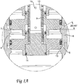
Fig. 1A shows, partly in section, a magnified part ofFig. 1 ; -
Fig. 1B shows, partly in section, yet a further magnified part ofFig. 1 ; and -
Fig. 2 is a perspective view of a part of the apparatus according to the invention. - The Drawings show only those details essential to an understanding of the present invention, and the positioning of the homogenizer valve in the homogenizer, which is well-known to the skilled reader of this specification, has been omitted.
- A
homogenizer valve 1 according to the present invention, as illustrated inFig. 1 , consists substantially of avalve housing 2 with aninlet 3 and an outlet 4 for the liquid which is to be homogenized, as well as a plurality ofvalve cones 5 and a plurality ofvalve seats 6. Thevalve cones 5 and thevalve seats 6 are disposed such that there occur throttles between them,homogenization gaps 7. - In the preferred embodiment, the
valve seats 6 are rotational-symmetric and have a central throughflow channel 8 for the liquid which is to be homogenized, constituting an extension of theinlet 3 of thehomogenization valve 1. Thevalve seats 6 are superposed on one another and they are secured to thevalve housing 2. - The
valve seats 6 further display abevel 12. Thebevel 12 is turned to face towards the centre of thehomogenizer valve 1. Thebevel 12 is turned to face away from theinlet 3 of thehomogenization valve 1. The bevel is between 20 and 45°, preferably 30° in relation to the horizontal plane. Thevalve seats 6 are preferably manufactured from surface treated, stainless steel, but other food approved materials may also occur. - The
valve cones 5, which are also rotation-symmetrical, have a threadedsurface 9 towards the centre of thehomogenization valve 1. In the centre of thehomogenizer valve 1 there is disposed a threadedrod 10 whose threads interlock in the threadedsurfaces 9 on thevalve cones 5. The meshed portions are sealed off, by means ofhygienic seals 14 of O-ring type, from the product which passes through the central through-flow channel 8. The threadedrod 10 has, adjacent theseals 14,bleeder holes 15. Thebleeder holes 15 may, in addition to being employed as bleeder route, also be used for indicating leakage if damage were to occur to theseals 14. In that theseals 14 are hygienic, there will be created ahygienic homogenizer valve 1 which satisfies the requirements of the food industry and which can be cleaned using conventional equipment. - The
valve cones 5 have abevel 13 towards the centre of thehomogenizer valve 1. Thebevel 13 is turned to face towards theinlet 3 of thehomogenizer valve 1. The bevel is between 20 and 45°, preferably 30° in relation to the horizontal plane. Thevalve cones 5 are preferably manufactured from surface treated, stainless steel, but other food approved materials may also occur. - The
valve cones 5, threaded together with the threadedrod 10, are pressurized, normally by means of an hydraulic orpneumatic piston 11, but may, in simpler versions, be pressurized by a set screw or grub screw which acts via a spring. Thevalve cones 5 are also movable, for example by the intermediary of the oil in the cylinder, in order to be able to take up the rapid flow variations which occur in the liquid which is to be homogenized. This elasticity is necessary in order to meet the flow variations which naturally occur in piston pumps. - The
valve cones 5 and the threadedrod 10 are positioned in thevalve housing 2 such that there occur, between thebevel 13 of thevalve cones 5 and thebevel 12 of thevalve seats 6,homogenization gaps 7 of a height h. The height h of thehomogenization gap 7 may be varied with a varied pressure and flow, in that thevalve cones 5 are moved more proximal to or more distal from the valve seats 6. In that thevalve cones 5 are threaded on the threadedrod 10, it is possible to obtain exactly the same height h of allhomogenization gaps 7 in thehomogenizer valve 1. - The
bevel 13 on thevalve cones 5 is of a greater extent than thebevel 12 on the valve seats 6. Thevalve cones 5 are placed against thevalve seats 6 so that there will be obtained projecting surfaces of thebevel 13 on both sides of thebevel 12. Thehomogenization gap 7 should not be too short, since increased wear may then be the result. Ashort homogenization gap 7 may also cause vibrations and disruptive noise. - In the
valve housing 2 of thehomogenizer valve 1 there are disposed a number ofvalve cones 5 and a number of valve seats 6.Fig. 1 shows sixvalve cones 5 and sixvalve seats 6. As a result, there will be obtained sixhomogenization gaps 7 superposed on one another. Ahomogenizer valve 1 according to the present invention may contain both more andfewer valve cones 5 andvalve seats 6, depending upon the desired capacity and practical application. By manufacturing thevalve housing 2 in parts, it is possible in a simple manner to assemble more orfewer valve cones 5 andvalve seats 6, respectively. - The liquid, normally milk, which is to be homogenized is led into the homogenizer where it is pressurized to approx. 10-25 Mpa. The milk normally has a fat content of 0.5-3.5 % and is at a temperature of 55-80°C.
- The liquid is led in through the
inlet 3 and passes through the through-flow channel 8. Thereafter, the liquid passes one of thedifferent homogenization gaps 7, where the homogenization takes place. The liquid is thereafter accumulated in thechannels 16. Since the liquid always strives to take the simplest route, there will be a relatively uniform distribution of liquid through thedifferent homogenization gaps 7. After the homogenization, the liquid passes out of thehomogenizer valve 1, through the outlet 4. In that thehomogenization gaps 7 are angled at 20-45°, preferably 30° in relation to the horizontal plane, there will be obtained a more uniform flow of the product, as well as reduced inlet losses on homogenization. - The gap height h is normally 50-200 µm. In the passage, an extremely rapid pressure drop is obtained down towards 0 Mpa, at the same time as the flow rate of the liquid increases, which results in the liquid beginning to boil. When the liquid leaves the
gap 7, the flow rate is reduced and the pressure once again increases. The liquid ceases to boil and the steam bubbles in the liquid implode. The entire process takes place within a few fractions of a second and, in the violent process where the high flow rate gives rise to turbulence and cavitation, the fat globules which are in the liquid will be split into smaller particles. - By obtaining a uniform distribution of the liquid between the
different homogenization gaps 7, there will be optimum utilisation of the increased gap length and a homogenizer with ahomogenizer valve 1 according to the present invention can handle several times as great a flow as a conventional homogenizer valve. At the same time, the homogenizer valve is governable for variations in the product flow, in that thepiston 11 may displace thevalve cones 5 in relation to thevalve seats 6 and thereby realise a different height h of thehomogenization gap 7. In that thevalve cones 5 are threaded on the threadedrod 10, all of thehomogenization gaps 7 will have the same gap height h. Allvalve cones 5, as well as the threadedrod 10, are regulated as a unit, so that all of thehomogenization gaps 7 always have the same gap height h. - As will have been apparent from the foregoing description, the present invention realises a homogenizer valve which may be employed for retrofitting in existing homogenizers, but which can handle a several times larger flow than a corresponding, conventional homogenizer valve. At the same time, the homogenizer valve may be regulated for instantaneous variations in pressure and flow. In that the homogenizer valve can be regulated, it also displays superior properties in respect of wear than prior art homogenizer valves. As a result of the design of the homogenizer valve, it is also relatively economical to manufacture.
- The present invention may be modified further without departing from the scope of the appended Claims.
Claims (7)
- A homogenizer valve (1) comprising a pressurized, movable valve cone (5), a valve seat (6) and a valve housing (2) surrounding the valve cone (5) and the valve seat (6), said valve cone (5) and said valve seat (6) being disposed so that a throttle occurs between them, constituting a homogenization gap (7), characterised in that two or more valve cones (5) are superposed on one another; and that two or more valve seats (6) are superposed on one another, so that two or more homogenization gaps (7) occur and in that the valve cones (5) are threaded on a threaded rod (10) centrally disposed in the valve housing (2).
- The homogenizer valve (1) as claimed in Claim 1, characterised in that valve cones (5) and valve seats (6) are rotation-symmetrical.
- The homogenizer valve (1) as claimed in any of the preceding Claims, characterised in that the homogenization gaps (7) are disposed at an angle in relation to the horizontal plane.
- The homogenizer valve (1) as claimed in Claim 3, characterised in that the homogenization gaps (7) are disposed at 20-45° in relation to the horizontal plane.
- The homogenizer valve (1) as claimed in Claim 4, characterised in that the homogenization gaps (7) are disposed at 30° in relation to the horizontal plane.
- The homogenizer valve (1) as claimed in Claim 1, characterised in that the valve cones (5) are disposed such that they are regulated together with the threaded rod (10) by means of a piston (11), so that all homogenization gaps (7) always have the same gap height h.
- The homogenizer valve (1) as claimed in Claim 1, characterised in that the valve seats (6) are secured to the valve housing (2).
Applications Claiming Priority (2)
| Application Number | Priority Date | Filing Date | Title |
|---|---|---|---|
| SE0800208A SE531925C2 (en) | 2008-01-29 | 2008-01-29 | homogenizer |
| PCT/SE2008/000688 WO2009096825A1 (en) | 2008-01-29 | 2008-12-09 | A homogenizer valve |
Publications (3)
| Publication Number | Publication Date |
|---|---|
| EP2237658A1 EP2237658A1 (en) | 2010-10-13 |
| EP2237658A4 EP2237658A4 (en) | 2014-10-08 |
| EP2237658B1 true EP2237658B1 (en) | 2018-07-25 |
Family
ID=40913017
Family Applications (1)
| Application Number | Title | Priority Date | Filing Date |
|---|---|---|---|
| EP08871639.4A Active EP2237658B1 (en) | 2008-01-29 | 2008-12-09 | A homogenizer valve |
Country Status (10)
| Country | Link |
|---|---|
| US (2) | US8944673B2 (en) |
| EP (1) | EP2237658B1 (en) |
| JP (1) | JP5087146B2 (en) |
| CN (1) | CN101909430B (en) |
| BR (1) | BRPI0821901A2 (en) |
| CZ (1) | CZ2010635A3 (en) |
| EA (1) | EA019265B1 (en) |
| MX (1) | MX2010008022A (en) |
| SE (1) | SE531925C2 (en) |
| WO (1) | WO2009096825A1 (en) |
Cited By (2)
| Publication number | Priority date | Publication date | Assignee | Title |
|---|---|---|---|---|
| IT202300000933A1 (en) * | 2023-01-23 | 2024-07-23 | Gea Mech Equipment Italia S P A | MULTI-GAP VALVE AND HOMOGENIZING APPARATUS COMPRISING SAID MULTI-GAP VALVE |
| RU2843537C2 (en) * | 2023-01-23 | 2025-07-14 | Геа Меканикал Эквипмент Италия С.П.А. | Multi-gap valve and homogenising device containing such multi-gap valve |
Families Citing this family (10)
| Publication number | Priority date | Publication date | Assignee | Title |
|---|---|---|---|---|
| SE531925C2 (en) * | 2008-01-29 | 2009-09-08 | Tetra Laval Holdings & Finance | homogenizer |
| SE535549C2 (en) * | 2010-12-22 | 2012-09-18 | Tetra Laval Holdings & Finance | homogenizer |
| US9399201B1 (en) * | 2012-09-28 | 2016-07-26 | Fristam Pumps, USA | Homogenizer for reducing the size of particles in fluids |
| CN104014262B (en) * | 2013-09-11 | 2016-03-02 | 曹结渝 | A kind of passive type agitator and apply the agitating device of this agitator |
| ITPR20130081A1 (en) * | 2013-10-21 | 2015-04-22 | Gea mechanical equipment italia spa | HOMOGENIZING VALVE, IN PARTICULAR FOR APPLICATION TO FIBROUS FLUIDS |
| WO2018034768A1 (en) * | 2016-08-19 | 2018-02-22 | Arisdyne Systems, Inc. | Homogenization device |
| CN112696503A (en) * | 2021-01-06 | 2021-04-23 | 西南石油大学 | Ultrahigh-temperature-resistant high-pressure air brake valve |
| DE102021004243B4 (en) | 2021-08-20 | 2023-11-30 | Gea Mechanical Equipment Italia S.P.A. | Valve and use of a valve |
| CN116221434B (en) * | 2023-05-05 | 2023-08-04 | 江南大学 | Homogenizing valve and homogenizing equipment |
| WO2026052205A1 (en) * | 2024-09-03 | 2026-03-12 | Wacker Chemie Ag | Method for producing finely divided emulsions |
Family Cites Families (22)
| Publication number | Priority date | Publication date | Assignee | Title |
|---|---|---|---|---|
| US1097474A (en) * | 1913-07-23 | 1914-05-19 | Wilhelm Gotthilf Schroeder | Device for mixing emulsions. |
| US2435884A (en) * | 1945-12-18 | 1948-02-10 | Kermit B Niles | Homogenizing unit |
| GB1002523A (en) * | 1963-01-23 | 1965-08-25 | Ultrasonic Ltd | Improvements relating to the production of aerosols and the like |
| US3473787A (en) * | 1967-12-18 | 1969-10-21 | Floyd M Bartlett | Method and apparatus for mixing drilling fluid |
| US4352573A (en) | 1980-01-29 | 1982-10-05 | Gaulin Corporation | Homogenizing method |
| JPS6128429A (en) | 1983-10-21 | 1986-02-08 | Kazuo Ogata | Split type homogenization apparatus of homogenizer |
| US4585357A (en) * | 1984-10-18 | 1986-04-29 | Kazuo Ogata | Homogenizer |
| JPH0227879Y2 (en) * | 1985-12-07 | 1990-07-26 | ||
| US5720551A (en) * | 1994-10-28 | 1998-02-24 | Shechter; Tal | Forming emulsions |
| US5749650A (en) * | 1997-03-13 | 1998-05-12 | Apv Homogenizer Group, A Division Of Apv North America, Inc. | Homogenization valve |
| SE509103C2 (en) | 1997-04-22 | 1998-12-07 | Tetra Laval Holdings & Finance | homogenizer |
| SE513519C2 (en) * | 1998-09-15 | 2000-09-25 | Tetra Laval Holdings & Finance | Method for homogenizing a pressurized liquid emulsion |
| US6305836B1 (en) * | 1999-07-09 | 2001-10-23 | Apv North America, Inc. | Force absorbing homogenization valve |
| US6238080B1 (en) * | 1999-07-09 | 2001-05-29 | Apv North America, Inc. | Homogenization valve with outside high pressure volume |
| US6244739B1 (en) * | 1999-07-09 | 2001-06-12 | Apv North America, Inc. | Valve members for a homogenization valve |
| US6502979B1 (en) * | 2000-11-20 | 2003-01-07 | Five Star Technologies, Inc. | Device and method for creating hydrodynamic cavitation in fluids |
| US6802639B2 (en) * | 2002-10-15 | 2004-10-12 | Five Star Technologies, Inc. | Homogenization device and method of using same |
| US20050150155A1 (en) * | 2004-01-09 | 2005-07-14 | Clean Fuels Technology, Inc., A Nevada Corporation. | Mixing apparatus and method for manufacturing an emulsified fuel |
| ITPR20070080A1 (en) * | 2007-10-23 | 2009-04-24 | Niro Soavi Spa | HOMOGENIZING VALVE |
| US8066425B2 (en) * | 2007-12-03 | 2011-11-29 | Chemical Services Limited | Homogenisation valve |
| SE531925C2 (en) * | 2008-01-29 | 2009-09-08 | Tetra Laval Holdings & Finance | homogenizer |
| SE535549C2 (en) * | 2010-12-22 | 2012-09-18 | Tetra Laval Holdings & Finance | homogenizer |
-
2008
- 2008-01-29 SE SE0800208A patent/SE531925C2/en not_active IP Right Cessation
- 2008-12-09 EP EP08871639.4A patent/EP2237658B1/en active Active
- 2008-12-09 CN CN2008801250187A patent/CN101909430B/en not_active Expired - Fee Related
- 2008-12-09 JP JP2010544906A patent/JP5087146B2/en not_active Expired - Fee Related
- 2008-12-09 EA EA201070901A patent/EA019265B1/en not_active IP Right Cessation
- 2008-12-09 WO PCT/SE2008/000688 patent/WO2009096825A1/en not_active Ceased
- 2008-12-09 MX MX2010008022A patent/MX2010008022A/en active IP Right Grant
- 2008-12-09 CZ CZ20100635A patent/CZ2010635A3/en unknown
- 2008-12-09 US US12/864,470 patent/US8944673B2/en active Active
- 2008-12-09 BR BRPI0821901-0A2A patent/BRPI0821901A2/en active Search and Examination
-
2015
- 2015-01-30 US US14/610,722 patent/US20150173322A1/en not_active Abandoned
Non-Patent Citations (1)
| Title |
|---|
| None * |
Cited By (4)
| Publication number | Priority date | Publication date | Assignee | Title |
|---|---|---|---|---|
| IT202300000933A1 (en) * | 2023-01-23 | 2024-07-23 | Gea Mech Equipment Italia S P A | MULTI-GAP VALVE AND HOMOGENIZING APPARATUS COMPRISING SAID MULTI-GAP VALVE |
| WO2024157058A1 (en) * | 2023-01-23 | 2024-08-02 | Gea Mechanical Equipment Italia S.P.A. | Multi-gap valve and homogenizing apparatus comprising said multi-gap valve |
| RU2843537C2 (en) * | 2023-01-23 | 2025-07-14 | Геа Меканикал Эквипмент Италия С.П.А. | Multi-gap valve and homogenising device containing such multi-gap valve |
| AU2023426268B2 (en) * | 2023-01-23 | 2026-04-09 | Gea Mechanical Equipment Italia S.P.A. | Multi-gap valve and homogenizing apparatus comprising said multi-gap valve |
Also Published As
| Publication number | Publication date |
|---|---|
| CN101909430B (en) | 2013-04-10 |
| CN101909430A (en) | 2010-12-08 |
| JP5087146B2 (en) | 2012-11-28 |
| US8944673B2 (en) | 2015-02-03 |
| EA201070901A1 (en) | 2011-02-28 |
| EA019265B1 (en) | 2014-02-28 |
| US20150173322A1 (en) | 2015-06-25 |
| BRPI0821901A2 (en) | 2014-10-14 |
| EP2237658A4 (en) | 2014-10-08 |
| EP2237658A1 (en) | 2010-10-13 |
| US20100329073A1 (en) | 2010-12-30 |
| CZ2010635A3 (en) | 2012-03-21 |
| JP2011514237A (en) | 2011-05-06 |
| SE0800208L (en) | 2009-07-30 |
| WO2009096825A1 (en) | 2009-08-06 |
| MX2010008022A (en) | 2010-08-04 |
| SE531925C2 (en) | 2009-09-08 |
Similar Documents
| Publication | Publication Date | Title |
|---|---|---|
| US8944673B2 (en) | Homogenizer valve | |
| EP1011851B1 (en) | Homogenizer valve | |
| EP2654933B1 (en) | Homogenizing valve | |
| US4352573A (en) | Homogenizing method | |
| EP2289613B1 (en) | Machine and method for emulsification | |
| WO1997031706A1 (en) | A homogenizer valve | |
| EP2869915B1 (en) | Homogenizer valve and method | |
| KR20150101973A (en) | The injection module for high pressure homogenizer | |
| EP3333472B1 (en) | A pulsation damper device and a method for pulsation damping of a pulsation damper device | |
| CN1031107C (en) | Ultra fine homogenizer |
Legal Events
| Date | Code | Title | Description |
|---|---|---|---|
| PUAI | Public reference made under article 153(3) epc to a published international application that has entered the european phase |
Free format text: ORIGINAL CODE: 0009012 |
|
| 17P | Request for examination filed |
Effective date: 20100830 |
|
| AK | Designated contracting states |
Kind code of ref document: A1 Designated state(s): AT BE BG CH CY CZ DE DK EE ES FI FR GB GR HR HU IE IS IT LI LT LU LV MC MT NL NO PL PT RO SE SI SK TR |
|
| AX | Request for extension of the european patent |
Extension state: AL BA MK RS |
|
| DAX | Request for extension of the european patent (deleted) | ||
| RAP1 | Party data changed (applicant data changed or rights of an application transferred) |
Owner name: TETRA LAVAL HOLDINGS & FINANCE S.A. |
|
| A4 | Supplementary search report drawn up and despatched |
Effective date: 20140910 |
|
| RIC1 | Information provided on ipc code assigned before grant |
Ipc: A01J 11/16 20060101AFI20140904BHEP Ipc: B01F 5/06 20060101ALI20140904BHEP Ipc: B01F 5/08 20060101ALI20140904BHEP |
|
| STAA | Information on the status of an ep patent application or granted ep patent |
Free format text: STATUS: EXAMINATION IS IN PROGRESS |
|
| 17Q | First examination report despatched |
Effective date: 20170220 |
|
| GRAP | Despatch of communication of intention to grant a patent |
Free format text: ORIGINAL CODE: EPIDOSNIGR1 |
|
| STAA | Information on the status of an ep patent application or granted ep patent |
Free format text: STATUS: GRANT OF PATENT IS INTENDED |
|
| INTG | Intention to grant announced |
Effective date: 20180215 |
|
| GRAS | Grant fee paid |
Free format text: ORIGINAL CODE: EPIDOSNIGR3 |
|
| GRAA | (expected) grant |
Free format text: ORIGINAL CODE: 0009210 |
|
| STAA | Information on the status of an ep patent application or granted ep patent |
Free format text: STATUS: THE PATENT HAS BEEN GRANTED |
|
| AK | Designated contracting states |
Kind code of ref document: B1 Designated state(s): AT BE BG CH CY CZ DE DK EE ES FI FR GB GR HR HU IE IS IT LI LT LU LV MC MT NL NO PL PT RO SE SI SK TR |
|
| REG | Reference to a national code |
Ref country code: GB Ref legal event code: FG4D |
|
| REG | Reference to a national code |
Ref country code: CH Ref legal event code: EP |
|
| REG | Reference to a national code |
Ref country code: AT Ref legal event code: REF Ref document number: 1020789 Country of ref document: AT Kind code of ref document: T Effective date: 20180815 |
|
| REG | Reference to a national code |
Ref country code: DE Ref legal event code: R096 Ref document number: 602008056182 Country of ref document: DE |
|
| REG | Reference to a national code |
Ref country code: IE Ref legal event code: FG4D |
|
| REG | Reference to a national code |
Ref country code: NL Ref legal event code: FP |
|
| REG | Reference to a national code |
Ref country code: LT Ref legal event code: MG4D |
|
| REG | Reference to a national code |
Ref country code: AT Ref legal event code: MK05 Ref document number: 1020789 Country of ref document: AT Kind code of ref document: T Effective date: 20180725 |
|
| PG25 | Lapsed in a contracting state [announced via postgrant information from national office to epo] |
Ref country code: BG Free format text: LAPSE BECAUSE OF FAILURE TO SUBMIT A TRANSLATION OF THE DESCRIPTION OR TO PAY THE FEE WITHIN THE PRESCRIBED TIME-LIMIT Effective date: 20181025 Ref country code: NO Free format text: LAPSE BECAUSE OF FAILURE TO SUBMIT A TRANSLATION OF THE DESCRIPTION OR TO PAY THE FEE WITHIN THE PRESCRIBED TIME-LIMIT Effective date: 20181025 Ref country code: AT Free format text: LAPSE BECAUSE OF FAILURE TO SUBMIT A TRANSLATION OF THE DESCRIPTION OR TO PAY THE FEE WITHIN THE PRESCRIBED TIME-LIMIT Effective date: 20180725 Ref country code: IS Free format text: LAPSE BECAUSE OF FAILURE TO SUBMIT A TRANSLATION OF THE DESCRIPTION OR TO PAY THE FEE WITHIN THE PRESCRIBED TIME-LIMIT Effective date: 20181125 Ref country code: GR Free format text: LAPSE BECAUSE OF FAILURE TO SUBMIT A TRANSLATION OF THE DESCRIPTION OR TO PAY THE FEE WITHIN THE PRESCRIBED TIME-LIMIT Effective date: 20181026 Ref country code: PL Free format text: LAPSE BECAUSE OF FAILURE TO SUBMIT A TRANSLATION OF THE DESCRIPTION OR TO PAY THE FEE WITHIN THE PRESCRIBED TIME-LIMIT Effective date: 20180725 Ref country code: SE Free format text: LAPSE BECAUSE OF FAILURE TO SUBMIT A TRANSLATION OF THE DESCRIPTION OR TO PAY THE FEE WITHIN THE PRESCRIBED TIME-LIMIT Effective date: 20180725 Ref country code: FI Free format text: LAPSE BECAUSE OF FAILURE TO SUBMIT A TRANSLATION OF THE DESCRIPTION OR TO PAY THE FEE WITHIN THE PRESCRIBED TIME-LIMIT Effective date: 20180725 Ref country code: LT Free format text: LAPSE BECAUSE OF FAILURE TO SUBMIT A TRANSLATION OF THE DESCRIPTION OR TO PAY THE FEE WITHIN THE PRESCRIBED TIME-LIMIT Effective date: 20180725 |
|
| PG25 | Lapsed in a contracting state [announced via postgrant information from national office to epo] |
Ref country code: ES Free format text: LAPSE BECAUSE OF FAILURE TO SUBMIT A TRANSLATION OF THE DESCRIPTION OR TO PAY THE FEE WITHIN THE PRESCRIBED TIME-LIMIT Effective date: 20180725 Ref country code: LV Free format text: LAPSE BECAUSE OF FAILURE TO SUBMIT A TRANSLATION OF THE DESCRIPTION OR TO PAY THE FEE WITHIN THE PRESCRIBED TIME-LIMIT Effective date: 20180725 Ref country code: HR Free format text: LAPSE BECAUSE OF FAILURE TO SUBMIT A TRANSLATION OF THE DESCRIPTION OR TO PAY THE FEE WITHIN THE PRESCRIBED TIME-LIMIT Effective date: 20180725 |
|
| REG | Reference to a national code |
Ref country code: DE Ref legal event code: R097 Ref document number: 602008056182 Country of ref document: DE |
|
| PG25 | Lapsed in a contracting state [announced via postgrant information from national office to epo] |
Ref country code: EE Free format text: LAPSE BECAUSE OF FAILURE TO SUBMIT A TRANSLATION OF THE DESCRIPTION OR TO PAY THE FEE WITHIN THE PRESCRIBED TIME-LIMIT Effective date: 20180725 Ref country code: CZ Free format text: LAPSE BECAUSE OF FAILURE TO SUBMIT A TRANSLATION OF THE DESCRIPTION OR TO PAY THE FEE WITHIN THE PRESCRIBED TIME-LIMIT Effective date: 20180725 Ref country code: RO Free format text: LAPSE BECAUSE OF FAILURE TO SUBMIT A TRANSLATION OF THE DESCRIPTION OR TO PAY THE FEE WITHIN THE PRESCRIBED TIME-LIMIT Effective date: 20180725 |
|
| PG25 | Lapsed in a contracting state [announced via postgrant information from national office to epo] |
Ref country code: SK Free format text: LAPSE BECAUSE OF FAILURE TO SUBMIT A TRANSLATION OF THE DESCRIPTION OR TO PAY THE FEE WITHIN THE PRESCRIBED TIME-LIMIT Effective date: 20180725 Ref country code: DK Free format text: LAPSE BECAUSE OF FAILURE TO SUBMIT A TRANSLATION OF THE DESCRIPTION OR TO PAY THE FEE WITHIN THE PRESCRIBED TIME-LIMIT Effective date: 20180725 |
|
| PLBE | No opposition filed within time limit |
Free format text: ORIGINAL CODE: 0009261 |
|
| STAA | Information on the status of an ep patent application or granted ep patent |
Free format text: STATUS: NO OPPOSITION FILED WITHIN TIME LIMIT |
|
| 26N | No opposition filed |
Effective date: 20190426 |
|
| REG | Reference to a national code |
Ref country code: CH Ref legal event code: PL |
|
| GBPC | Gb: european patent ceased through non-payment of renewal fee |
Effective date: 20181209 |
|
| PG25 | Lapsed in a contracting state [announced via postgrant information from national office to epo] |
Ref country code: MC Free format text: LAPSE BECAUSE OF FAILURE TO SUBMIT A TRANSLATION OF THE DESCRIPTION OR TO PAY THE FEE WITHIN THE PRESCRIBED TIME-LIMIT Effective date: 20180725 Ref country code: LU Free format text: LAPSE BECAUSE OF NON-PAYMENT OF DUE FEES Effective date: 20181209 Ref country code: SI Free format text: LAPSE BECAUSE OF FAILURE TO SUBMIT A TRANSLATION OF THE DESCRIPTION OR TO PAY THE FEE WITHIN THE PRESCRIBED TIME-LIMIT Effective date: 20180725 |
|
| REG | Reference to a national code |
Ref country code: IE Ref legal event code: MM4A |
|
| REG | Reference to a national code |
Ref country code: BE Ref legal event code: MM Effective date: 20181231 |
|
| PG25 | Lapsed in a contracting state [announced via postgrant information from national office to epo] |
Ref country code: FR Free format text: LAPSE BECAUSE OF NON-PAYMENT OF DUE FEES Effective date: 20181231 Ref country code: IE Free format text: LAPSE BECAUSE OF NON-PAYMENT OF DUE FEES Effective date: 20181209 |
|
| PG25 | Lapsed in a contracting state [announced via postgrant information from national office to epo] |
Ref country code: BE Free format text: LAPSE BECAUSE OF NON-PAYMENT OF DUE FEES Effective date: 20181231 |
|
| PG25 | Lapsed in a contracting state [announced via postgrant information from national office to epo] |
Ref country code: GB Free format text: LAPSE BECAUSE OF NON-PAYMENT OF DUE FEES Effective date: 20181209 Ref country code: LI Free format text: LAPSE BECAUSE OF NON-PAYMENT OF DUE FEES Effective date: 20181231 Ref country code: CH Free format text: LAPSE BECAUSE OF NON-PAYMENT OF DUE FEES Effective date: 20181231 |
|
| PG25 | Lapsed in a contracting state [announced via postgrant information from national office to epo] |
Ref country code: MT Free format text: LAPSE BECAUSE OF NON-PAYMENT OF DUE FEES Effective date: 20181209 |
|
| PG25 | Lapsed in a contracting state [announced via postgrant information from national office to epo] |
Ref country code: TR Free format text: LAPSE BECAUSE OF FAILURE TO SUBMIT A TRANSLATION OF THE DESCRIPTION OR TO PAY THE FEE WITHIN THE PRESCRIBED TIME-LIMIT Effective date: 20180725 |
|
| PG25 | Lapsed in a contracting state [announced via postgrant information from national office to epo] |
Ref country code: PT Free format text: LAPSE BECAUSE OF FAILURE TO SUBMIT A TRANSLATION OF THE DESCRIPTION OR TO PAY THE FEE WITHIN THE PRESCRIBED TIME-LIMIT Effective date: 20180725 |
|
| PG25 | Lapsed in a contracting state [announced via postgrant information from national office to epo] |
Ref country code: CY Free format text: LAPSE BECAUSE OF FAILURE TO SUBMIT A TRANSLATION OF THE DESCRIPTION OR TO PAY THE FEE WITHIN THE PRESCRIBED TIME-LIMIT Effective date: 20180725 Ref country code: HU Free format text: LAPSE BECAUSE OF FAILURE TO SUBMIT A TRANSLATION OF THE DESCRIPTION OR TO PAY THE FEE WITHIN THE PRESCRIBED TIME-LIMIT; INVALID AB INITIO Effective date: 20081209 |
|
| P01 | Opt-out of the competence of the unified patent court (upc) registered |
Effective date: 20230426 |
|
| PGFP | Annual fee paid to national office [announced via postgrant information from national office to epo] |
Ref country code: NL Payment date: 20231226 Year of fee payment: 16 Ref country code: IT Payment date: 20231221 Year of fee payment: 16 |
|
| PGFP | Annual fee paid to national office [announced via postgrant information from national office to epo] |
Ref country code: DE Payment date: 20241227 Year of fee payment: 17 |
|
| REG | Reference to a national code |
Ref country code: NL Ref legal event code: MM Effective date: 20250101 |
|
| PG25 | Lapsed in a contracting state [announced via postgrant information from national office to epo] |
Ref country code: NL Free format text: LAPSE BECAUSE OF NON-PAYMENT OF DUE FEES Effective date: 20250101 |
|
| PG25 | Lapsed in a contracting state [announced via postgrant information from national office to epo] |
Ref country code: IT Free format text: LAPSE BECAUSE OF NON-PAYMENT OF DUE FEES Effective date: 20241209 |