EP2237484B1 - Haustechniksystem und Steuerungsverfahren dafür - Google Patents
Haustechniksystem und Steuerungsverfahren dafür Download PDFInfo
- Publication number
- EP2237484B1 EP2237484B1 EP10001110.5A EP10001110A EP2237484B1 EP 2237484 B1 EP2237484 B1 EP 2237484B1 EP 10001110 A EP10001110 A EP 10001110A EP 2237484 B1 EP2237484 B1 EP 2237484B1
- Authority
- EP
- European Patent Office
- Prior art keywords
- control point
- building equipment
- units
- equipment
- control
- Prior art date
- Legal status (The legal status is an assumption and is not a legal conclusion. Google has not performed a legal analysis and makes no representation as to the accuracy of the status listed.)
- Not-in-force
Links
Images

Classifications
-
- H—ELECTRICITY
- H04—ELECTRIC COMMUNICATION TECHNIQUE
- H04L—TRANSMISSION OF DIGITAL INFORMATION, e.g. TELEGRAPHIC COMMUNICATION
- H04L12/00—Data switching networks
- H04L12/28—Data switching networks characterised by path configuration, e.g. LAN [Local Area Networks] or WAN [Wide Area Networks]
- H04L12/2803—Home automation networks
- H04L12/283—Processing of data at an internetworking point of a home automation network
- H04L12/2834—Switching of information between an external network and a home network
-
- F—MECHANICAL ENGINEERING; LIGHTING; HEATING; WEAPONS; BLASTING
- F24—HEATING; RANGES; VENTILATING
- F24F—AIR-CONDITIONING; AIR-HUMIDIFICATION; VENTILATION; USE OF AIR CURRENTS FOR SCREENING
- F24F11/00—Control or safety arrangements
- F24F11/30—Control or safety arrangements for purposes related to the operation of the system, e.g. for safety or monitoring
-
- F—MECHANICAL ENGINEERING; LIGHTING; HEATING; WEAPONS; BLASTING
- F24—HEATING; RANGES; VENTILATING
- F24F—AIR-CONDITIONING; AIR-HUMIDIFICATION; VENTILATION; USE OF AIR CURRENTS FOR SCREENING
- F24F11/00—Control or safety arrangements
- F24F11/50—Control or safety arrangements characterised by user interfaces or communication
- F24F11/52—Indication arrangements, e.g. displays
-
- H—ELECTRICITY
- H04—ELECTRIC COMMUNICATION TECHNIQUE
- H04L—TRANSMISSION OF DIGITAL INFORMATION, e.g. TELEGRAPHIC COMMUNICATION
- H04L12/00—Data switching networks
- H04L12/28—Data switching networks characterised by path configuration, e.g. LAN [Local Area Networks] or WAN [Wide Area Networks]
- H04L12/2803—Home automation networks
- H04L12/2807—Exchanging configuration information on appliance services in a home automation network
- H04L12/2809—Exchanging configuration information on appliance services in a home automation network indicating that an appliance service is present in a home automation network
-
- H—ELECTRICITY
- H04—ELECTRIC COMMUNICATION TECHNIQUE
- H04L—TRANSMISSION OF DIGITAL INFORMATION, e.g. TELEGRAPHIC COMMUNICATION
- H04L12/00—Data switching networks
- H04L12/28—Data switching networks characterised by path configuration, e.g. LAN [Local Area Networks] or WAN [Wide Area Networks]
- H04L12/2803—Home automation networks
- H04L12/2816—Controlling appliance services of a home automation network by calling their functionalities
-
- H—ELECTRICITY
- H04—ELECTRIC COMMUNICATION TECHNIQUE
- H04L—TRANSMISSION OF DIGITAL INFORMATION, e.g. TELEGRAPHIC COMMUNICATION
- H04L12/00—Data switching networks
- H04L12/28—Data switching networks characterised by path configuration, e.g. LAN [Local Area Networks] or WAN [Wide Area Networks]
- H04L12/2803—Home automation networks
- H04L2012/2847—Home automation networks characterised by the type of home appliance used
- H04L2012/285—Generic home appliances, e.g. refrigerators
-
- H—ELECTRICITY
- H04—ELECTRIC COMMUNICATION TECHNIQUE
- H04L—TRANSMISSION OF DIGITAL INFORMATION, e.g. TELEGRAPHIC COMMUNICATION
- H04L67/00—Network arrangements or protocols for supporting network services or applications
- H04L67/50—Network services
- H04L67/75—Indicating network or usage conditions on the user display
Definitions
- the present invention relates to a building equipment system, which is capable of easily registering building equipment units using a central control unit by automatically assigning attribute information and control point addresses of the building equipment units when the building equipment units are connected, and a control method thereof.
- a building equipment system includes a plurality of building equipment units including illumination apparatuses, heating apparatuses and air conditioners.
- the building equipment system controls the plurality of building equipment units using a central control unit so as to efficiently perform management and control.
- the building equipment system checks the operation states of the plurality of multi-type air conditioners, and controls the plurality of multi-type air conditioners using the central control unit according to the checked result.
- control points of indoor and outdoor units of the plurality of multi-type air conditioners are registered and set, an engineer individually sets and registers control point setting information of the indoor and outdoor units connected to the central control unit.
- the central control unit receives the control point setting information from the engineer and sets and registers the indoor and outdoor units.
- US 2005209739 A1 discloses an airconditioner system for integrating multiple areas, wherein a plurality of multi-airconditioners are grouped into some groups.
- a CPU controls individual multi-airconditioner groups to be operated simultaneously. If a failure occurs in one multi-airconditioner group, the remaining multi-airconditioner groups can be normally controlled.
- US 5436147 A discloses an air conditioning control system ensuring the desired full utility so that the operation of a plurality of air conditioners installed in a building can be controlled and monitored at a plurality of spots in the building.
- the air conditioning control system includes a building's central monitor board controlling and monitoring the operation of the individual air conditioners, and a centralized control unit relaying air conditioner control information outputted from the central monitor board and information indicating the operation status of the individual air conditioners, each of the central monitor board and the centralized control unit including an input part inputting the control information to the individual air conditioners and a display part displaying the operation status information regarding the individual air conditioners.
- the centralized control unit further includes a decision part deciding to identify newest control information inputted from the input part of each of the central monitor board and the centralized control unit and a transmitter part transmitting this newest control information to the individual air conditioners.
- WO 0048376 A1 discloses a building information system and method processes building-related data associated with a building.
- the building-related data is associatively stored in a database.
- a client interface communicates the building-related data between a client application and the data interface.
- Other services include a polling service for periodically detecting point data, a metering service for periodically detecting meter data, and a rates service providing real-time price control.
- EP 1956758 A2 discloses a method and apparatus for automatically recognizing a device of a building management system.
- An advantage of the present invention is to provide a building equipment system, which is capable of easily registering building equipment units using a central control unit by automatically assigning attribute information and control point addresses of the building equipment units when the building equipment units are connected, and a control method thereof.
- a building equipment system according to claim 1 and a method of controlling a building equipment system according to claim 9 are provided.
- FIG. 1 is a systematic diagram of a building equipment system according to the present invention
- FIG. 2 is a functional block diagram showing the configuration of a building equipment system according to a first embodiment of the present invention
- FIG. 3 is a flowchart illustrating a method of controlling a building equipment system according to the first embodiment of the present invention
- FIG. 4 is a functional block diagram showing the configuration of a building equipment system according to a second embodiment of the present invention.
- FIG. 5 is a flowchart illustrating a method of controlling a building equipment system according to the second embodiment of the present invention.
- FIG. 1 is a systematic diagram of a building equipment system according to the present invention.
- the building equipment system includes first to eighth building equipment units 1 to 8, a gateway unit 10 and a central control unit 20.
- the first to eighth building equipment units 1 to 8 are of different types, and are equipment units that may be electronically controlled in the present embodiment, such as an indoor unit, an outdoor unit, a cooling tower, a motor, and a compressor included in at least one of a water cooling type air conditioner and an air cooling type air conditioner, and are mounted for conditioning an indoor space of a large-sized building and a high-rise building.
- the equipment units included in the water cooling type air conditioner and the air cooling type air conditioner mounted in the building are described as the first to eighth building equipment units 1 to 8 in the present embodiment, the present invention is not limited thereto and illumination apparatuses and a plurality of sensors may be included.
- the gateway unit 10 is connected to the first to eighth building units 1 to 8 by wiring, and a Direct Digital Controller (DDC) and a Programmable Logic Controller (PLC) may be used.
- DDC Direct Digital Controller
- PLC Programmable Logic Controller
- the PLC controls the first to eighth building equipment units 1 to 8 by connecting to a control contact point
- the DDC controls the first to eighth building equipment units 1 to 8 connected not based on an Open protocol as in the PLC, but based on RS485 communication or Ethernet.
- the gateway unit 10 recognizes the equipment types and generates control point setting information using an equipment library describing the various equipment types, when the first to eighth building equipment units 1 to 8 are each separately connected.
- the central control unit 20 receives the control point setting information generated by the gateway unit 10 through RS485 communication or Ethernet, and displays an object image and a control screen for displaying the operation of each of the first to eighth building equipment units 1 to 8 based on the control point setting information.
- the central control unit 20 may be a computer or other central processing unit and centrally controls the first to eighth building equipment units 1 to 8 connected to the gateway unit 10.
- the gateway unit 10 and the central control unit 20 are connected through RS485 communication or Ethernet communication in the present building equipment system, other protocols may be used.
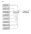
- FIG. 2 is a functional block diagram showing the configuration of a building equipment system according to a first embodiment of the present invention.
- the present building equipment system includes first to eighth building equipment units 1 to 8, a gateway unit 10 and a central control unit 20.
- first to eighth building equipment units 1 to 8 include boiler units 1 and 2, cooling tower units 3 and 4, first and second indoor units 5 and 6 and first and second outdoor units 7 and 8.
- the present invention is not limited thereto and other building equipment units may be included.
- the boiler units 1 and 2 and the cooling tower units 3 and 4 include other building equipment units included in a boiler and a cooling tower, respectively.
- the gateway unit 10 includes a connection unit 12 to which the first to eighth building equipment units 1 to 8 are connected, and an equipment recognition unit 14 for recognizing the equipment types of the first to eighth building equipment units 1 to 8 connected to the connection unit 12 and generating control point setting information using an equipment library describing the various equipment types.
- the connection unit 12 includes first, second, third and fourth connection terminals 12_1, 12_2, 12_3 and 12_4 such that the boiler units 1 and 2, the cooling tower units 3 and 4, the first and second indoor units 5 and 6 and the first and second outdoor units 7 and 8 of the first to eighth building equipment units 1 to 8 are separately connected.
- Each of the first, second, third and fourth connection terminals 12_1, 12_2, 12_3 and 12_4 is connected to the equipment recognition unit 14 by an RS485 communication line P1.
- the equipment recognition unit 14 recognizes the equipment types of the boiler units 1 and 2, the cooling tower units 3 and 4, the first and second indoor units 5 and 6 and the first and second outdoor units 7 and 8 separately connected to the first, second, third and fourth connection terminals 12_1, 12_2, 12_3 and 12_4 through RS485 communication lines.
- the equipment recognition unit 14 generates the control point setting information using the equipment library describing the various equipment types.
- the equipment library includes attribute information and control point addresses for the various equipment types and is used to assign a regular point control address according to the equipment type.
- the control point addresses may be combination of gateway unit number, equipment type, connection terminal number, and connection point of a connection terminal.
- the attribute information may be such as equipment type, model number and control attributes (power on/off, temperature, fan speed, etc.) and attribute range (maximum temperature and minimum temperature, etc.).
- the equipment recognition unit 14 generates the control point setting information including the attribute information and the control point addresses of the boiler units 1 and 2, the cooling tower units 3 and 4, the first and second indoor units 5 and 6 and the first and second outdoor units 7 and 8.
- the equipment recognition unit 14 applies code numbers or identifiers according to the equipment types and generates the control point setting information in which the attribution information and the control point addresses set in the equipment library are automatically assigned according to the code numbers or the identifiers.
- the central control unit 20 displays an object image and a control screen for displaying the operation of each of the boiler units 1 and 2, the cooling tower units 3 and 4, the first and second indoor units 5 and 6 and the first and second outdoor units 7 and 8 according to the control point setting information received from the gateway unit 10.
- the central control unit 20 includes a display unit 22 for displaying the object image and the control screen, an input unit 24 for inputting a selection command and an operation command related to the object image, and a control unit 26 for controlling the object image and the control screen to be displayed on the display unit 22 and controlling the boiler units 1 and 2, the cooling tower units 3 and 4, the first and second indoor units 5 and 6 and the first and second outdoor units 7 and 8 according to the selection command and the operation command received from the input unit 24.
- control unit 26 controls the object image including the control point setting information to be displayed on the display unit 22, displays the attribute information and the control point addresses on the display unit 22 when the selection command is input by the input unit 24, and displays the control screen on the display unit 22 when the operation command is input.
- the building equipment system automatically generates the control point setting information using the equipment library in which the attribute information and the control point addresses are stored according to the equipment types of the building equipment units, it is possible to reduce a registration time using the control point setting information which otherwise would be manually input by an engineer. This reduces the installation time and minimizes errors in registering the building equipment when the object image is displayed by the central control unit.
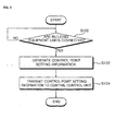
- FIG. 3 is a flowchart illustrating a method of controlling a building equipment system according to the first embodiment of the present invention.
- the present building equipment system determines whether or not any building equipment units are connected (S100).
- the gateway unit 10 determines whether or not any of the first to eighth building equipment units 1 to 8 are connected to the connection unit 12 through the RS communication or Ethernet communication line.
- the gateway unit 10 performs RS communication using the RS communication line P1 in order to determine whether or not any of the first to eighth building equipment units 1 to 8 are connected to the first to fourth connection terminals 12_1 to 12_4 of the connection unit 12, and determines that the building equipment units are connected, if communication is possible.
- control point setting information is generated (S102).
- the gateway unit 10 generates the control point setting information including the attribute information and the control point addresses using the equipment library according to the equipment types of the first to eighth building equipment units 1 to 8, when the first to eighth building equipment units 1 to 8 are connected to the first to fourth connection terminals 12_1 to 12_4.
- the equipment recognition unit 14 recognizes if the first to eighth building equipment units 1 to 8 are connected and automatically assigns the attribute information and the control point addresses using the equipment library according to the equipment types of the first to eighth building equipment units 1 to 8 connected through RS communication lines.
- the equipment recognition unit 14 generates the control point setting information including the attribute information and the control point addresses.
- the attribution information and the control point addresses may be displayed by code numbers or identifiers according to the equipment types.
- the control point setting information is transmitted to the central control unit (S 104).
- the gateway unit 10 transmits the control point setting information of the connected first to eighth building equipment units 1 to 8 to the central control unit 20.
- the central control unit 20 displays the object image, and the attribute information and the control point addresses included in the object image according to the control point setting information.
- the central control unit 20 can individually or centrally control the first to eighth building equipment units 1 to 8 using the same object image as the first to eighth building equipment units 1 to 8.
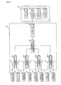
- FIG. 4 is a functional block diagram showing the configuration of a building equipment system according to a second embodiment of the present invention.
- the present building equipment system includes first to eighth building equipment units 31 to 38, a gateway unit 40 and a central control unit 50.
- the first to eighth building equipment units 31 to 3 8 include boiler units 31 and 32, cooling tower units 33 and 34, first and second indoor units 35 and 36 and first and second outdoor units 37 and 38.
- the boiler units 31 and 32, the cooling tower units 33 and 34, the first and second indoor units 35 and 36 and the first and second outdoor units 37 and 38 are separately connected to the gateway unit 40 according to the equipment types.
- the gateway unit 40 includes a connection unit 42 to which the first to eighth building equipment units 31 to 38 are connected, an equipment recognition unit 44 for recognizing the equipment types of the first to eighth building equipment units 31 to 38 connected to the connection unit 42 and for generating the control point information using an equipment library describing the various equipment types, and a control unit 46 for mapping the control point information to control point basic information of the equipment types of the first to eighth building equipment units 31 to 38 set by the central control unit 50 and generating control point setting information.
- the connection unit 42 includes first, second third and fourth connection terminals 42_1, 42_2, 42_3 and 42_4 such that the boiler units 31 and 32, the cooling tower units 33 and 34, the first and second indoor units 35 and 36 and the first and second outdoor units 37 and 38 of the first to eighth building equipment units 31 to 38 are separately connected.
- Each of the first, second, third and fourth connection terminals 42_1, 42_2, 42_3 and 42_4 is connected to the equipment recognition unit 44 by an RS485 communication line P1 for RS485 communication.
- the equipment recognition unit 44 recognizes the equipment types of the boiler units 31 and 32, the cooling tower units 33 and 34, the first and second indoor units 35 and 36 and the first and second outdoor units 37 and 38 each separately connected to the first, second, third and fourth connection terminals 42_1, 42_2, 42_3 and 42_4 through RS485 communication.
- the equipment recognition unit 44 generates the control point information using the equipment library describing the various equipment types.
- the equipment library includes attribute information and control point addresses set according to the equipment types and is used to assign regular point control addresses according to the equipment types.
- the equipment recognition unit 44 generates the control point information including the attribute information and the control point addresses of the boiler units 31 and 32, the cooling tower units 33 and 34, the first and second indoor units 35 and 36 and the first and second outdoor units 37 and 38.
- the equipment recognition unit 44 applies code numbers or identifiers according to the equipment types and generates the control point information in which the attribution information and the control point addresses set in the equipment library are automatically assigned according to the code numbers or the identifiers.
- the control unit 46 maps the control point information generated by the equipment recognition unit 44 to the control point basic information transmitted from the central control unit 50, and automatically generates the control point setting information.
- the control point basic information is setting information (model number, control attributes by equipment type and default value of attribute, etc.) related to the operation of the equipment types of the boiler units 31 and 32, the cooling tower units 33 and 34, the first and second indoor units 35 and 36 and the first and second outdoor units 37 and 38, and the control point information includes the attribute information and the control point addresses of the boiler units 31 and 32, the cooling tower units 33 and 34, the first and second indoor units 35 and 36 and the first and second outdoor units 37 and 38.
- control unit 46 maps the control point information to the control point basic information and generates the control point setting information including the setting information, the attribute information and the control point addresses of the boiler units 31 and 32, the cooling tower units 33 and 34, the first and second indoor units 35 and 36 and the first and second outdoor units 37 and 38.
- control unit 46 maps the setting information, the attribute information and the control point addresses to one object. If control attributes of the control point information is similar to control attributes of control point basic information, then the control unit 46 may map the setting information, the attribute information and the control point addresses to one object.
- the setting information includes an object image to be displayed by the central control unit 50.
- the central control unit 50 displays the object image and a control screen for displaying the operation of each of the boiler units 31 and 32, the cooling tower units 33 and 34, the first and second indoor units 35 and 36 and the first and second outdoor units 37 and 38 according to the control point setting information received from the gateway unit 40.
- the central control unit 50 includes a display unit 52 for displaying the object image and the control screen, an input unit 54 for inputting a selection command and an operation command relating to the object image, and a control unit 56 for controlling the object image and the control screen to be displayed on the display unit 52 and controlling the boiler units 31 and 32, the cooling tower units 33 and 34, the first and second indoor units 35 and 36 and the first and second outdoor units 37 and 38 according to the selection command and the operation command received from the input unit 54.
- the central control unit 50 further includes a storage unit 58 for storing the control point information.
- the control point information is the setting information relating to the operation of each of the boiler units 31 and 32, the cooling tower units 33 and 34, the first and second indoor units 35 and 36 and the first and second outdoor units 37 and 38, and the setting information includes the equipment types and characteristic information according to use.
- the control unit 56 controls the object image and the control screen to be displayed on the display unit 52 according to the control point setting information transmitted from the gateway unit 40, displays the attribute information and the control point addresses on the display unit 52 when the selection command is input using the input unit 54, and displays the control screen on the display unit 52 when the operation command is input.
- the control unit 56 updates the control point basic information using the control point setting information and stores the updated information in the storage unit 58.
- gateway unit 40 Although one gateway unit 40 is used in FIG. 4 , at least two gateway units may be included. If at least two gateway units are included, the first to eighth building equipment units 31 to 38 may be divided according to the equipment types.
- gateway units 40 If at least two gateway units 40 are mounted, a plurality of DDCs and PLCs may be commonly mounted.
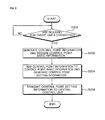
- FIG. 5 is a flowchart illustrating a method of controlling a building equipment system according to the second embodiment of the present invention.
- the present building equipment system determines whether or not any of the building equipment units are connected (S200).
- the gateway unit 40 determines whether or not any of the first to eighth building equipment units 31 to 38 are connected to the connection unit 42 through RS communication or Ethernet communication line.
- the gateway unit 40 performs RS communication using the RS communication line P1 in order to determine whether or not any of the first to eighth building equipment units 31 to 38 are connected to the first to fourth connection terminals 42_1 to 42_4 of the connection unit 42, and determines that the building equipment units are connected, if communication is possible.
- control point information is generated according to the equipment types of the building equipment units and the control point basic information is received from the central control unit (S202).
- the gateway unit 40 generates the control point information according to the equipment types of the first to eighth building equipment units 31 to 38 and receives the control point basic information according to the equipment types from the central control unit 50, when the first to eighth building equipment units 31 to 38 are connected to the first to fourth connection terminals 42_1 to 42_4.
- the equipment recognition unit 44 recognizes the equipment types of the connected first to eighth building equipment units 31 to 38, and generates the control point information including the attribute information and the control point addresses using the equipment library according to the equipment types.
- the control unit 46 receives the control point basic information according to the equipment types from the central control unit 50.
- the control point information is mapped to the control point basic information so as to generate the control point setting information (S204).
- the gateway unit 40 maps the control point information of the first to eighth building equipment units 31 to 38 to the received control point basic information according to the equipment types, and then generates the control point setting information.
- control unit 46 maps the control point information, in which the attribute information and the control point addresses are automatically assigned using the equipment library according to the equipment types of the first to eighth building equipment units 31 to 38 by the equipment recognition unit 44, to the control point basic information which is the setting information of the equipment types of the first to eighth building equipment units 31 to 38 according to the same equipment types, and generates the control point setting information.
- the control point setting information includes the setting information, the attribute information and the control point addresses.
- the control point setting information is transmitted to the central control unit (S206).
- the gateway unit 40 transmits the control point setting information of the connected first to eighth building equipment units 31 to 38 to the central control unit 50.
- the central control unit 50 displays the object image, and the attribute information, the control point addresses and the setting information included in the object image according to the control point setting information.
- the central control unit 50 can individually or centrally control the first to eighth building equipment units 31 to 38 using the same object image as the first to eighth building equipment units 31 to 38.
Claims (13)
- Gebäudeanlagensystem, das umfasst:eine Gateway-Einheit (40), die dafür ausgelegt ist, Steueipunkt-Einstellinformationen zu erzeugen, wenn Gebäudeanlageeinheiten (31 bis 38) als Steuerpunkte angeschlossen werden; undeine zentrale Steuereinheit (50), die dafür ausgelegt ist, ein Objektbild, das jeder der Gebäudeanlageeinheiten (31 bis 38) entspricht, und einen Steuerbildschirm zum Anzeigen eines Betriebs jeder der Gebäudeanlageeinheiten (31 bis 38) auf der Grundlage der Steuerpunkt-Einstellinformationen anzuzeigen;dadurch gekennzeichnet, dass die Gateway-Einheit (40) umfasst:eine Anschlusseinheit (42), an die die Gebäudeanlageeinheiten (31 bis 38) angeschlossen werden; undeine Anlagenerkennungseinheit (44), die dafür ausgelegt ist, Anlagetypen der Gebäudeanlageeinheiten (31 bis 38), die an die Anschlusseinheit (42) angeschlossen sind, zu erkennen, und dafür ausgelegt ist, Steuerpunktinformationen unter Verwendung einer Anlagenbibliothek, die mit den Anlagetypen koinzident ist, zu erzeugen;eine Steuereinheit (46), die dafür ausgelegt ist, die Steuerpunktinformationen auf Steuerpunkt-Basisinformationen der Anlagetypen der Gebäudeanlageeinheiten (31 bis 38), die durch die zentrale Steuereinheit (50) eingestellt werden, abzubilden, und dafür ausgelegt ist, die Steuerpunkt-Einstellinformationen zu erzeugen.
- Gebäudeanlagensystem nach Anspruch 1, wobei die Anlagenerkennungseinheit (44) dafür ausgelegt ist, Steuerpunkt-Einstellinformationen unter Verwendung einer Anlagenbibliothek, die die verschiedenen Anlagetypen beschreibt, zu erzeugen.
- Gebäudeanlagensystem nach Anspruch 2, wobei die Anschlusseinheit (42) mehrere Verbindungsanschlüsse (42_1 bis 42_4) umfasst, die entsprechend den Anlagetypen der Gebäudeanlageeinheiten (31 bis 38) getrennt angeschlossen sind.
- Gebäudeanlagensystem nach Anspruch 2, wobei:Attributinformationen und Steuerpunktadressen auf der Grundlage der Anlagetypen der Gebäudeanlageeinheiten (31 bis 38) in der Anlagenbibliothek eingestellt werden und die Steuerpunkt-Einstellinformationen, die Attributinformationen und die Steuerpunktadressen der Gebäudeanlageeinheiten (31 bis 38) enthalten.
- Gebäudeanlagensystem nach Anspruch 1, wobei die zentrale Steuereinheit (50) umfasst:eine Anzeigeeinheit (52), die dafür ausgelegt ist, das Objektbild und den Steuerbildschirm anzuzeigen;eine Eingabeeinheit (54), die dafür ausgelegt ist, einen Auswahlbefehl und einen Betriebsbefehl des Objektbildes einzugeben; undeine Steuereinheit (56), die dafür ausgelegt ist, das Objektbild und den Steuerbildschirm, die auf der Anzeigeeinheit angezeigt werden sollen, zu steuern, und dafür ausgelegt ist, die Gebäudeanlageeinheiten (31 bis 38) in Übereinstimmung mit dem Auswahlbefehl und dem Betriebsbefehl von der Eingabeeinheit (54) zu steuern.
- Gebäudeanlagensystem nach Anspruch 5, wobei
die Steuerpunkt-Einstellinformationen Attributinformationen und Steueipunktadressen der Gebäudeanlageeinheiten (31 bis 38) enthalten und
die Steuereinheit (56) dafür ausgelegt ist, die Attributinformationen und die Steueipunktadressen, die auf der Anzeigeeinheit (52) anzuzeigen sind, zu steuern, wenn der Auswahlbefehl des Objektbildes eingegeben wird. - Gebäudeanlagensystem nach Anspruch 1, wobei:die Steuerpunkt-Basisinformationen Einstellinformationen des Betriebs jeder der Gebäudeanlageeinheiten (31 bis 38) sind,die Steuerpunktinformationen Attributinformationen und Steueradressen der Gebäudeanlageeinheiten (31 bis 38) enthalten unddie Steuereinheit (46) dafür ausgelegt ist, die Steueipunkt-Einstellinformationen, auf die die Einstellinformationen, die Attributinformationen und die Steuerpunktadressen der Gebäudeanlageeinheiten (31 bis 38) abgebildet sind, zu erzeugen, und dafür ausgelegt ist, die Steuerpunkt-Einstellinformationen zu der zentralen Steuereinheit (50) zu senden.
- Gebäudeanlagesystem nach Anspruch 1, wobei die zentrale Steuereinheit (50) dafür ausgelegt ist, die Steuerpunkt-Basisinformationen unter Verwendung der Steuerpunkt-Einstellinformationen zu aktualisieren, wenn die Steueipunkt-Einstellinformationen eingegeben werden.
- Verfahren zum Steuern eines Gebäudeanlagensystems, wobei das Verfahren umfasst:Bestimmen (S200), ob Gebäudeanlageeinheiten (31 bis 38) an Steuerpunkte angeschlossen sind;Erkennen von Anlagetypen der Gebäudeanlageeinheiten (31 bis 38);Erzeugen (S202) von Steuerpunktinformationen unter Verwendung einer Anlagenbibliothek, die mit den Anlagetypen koinzident ist;Abbilden (S204) der Steuerpunktinformationen auf Steuerpunkt-Basisinformationen der Anlagetypen der Gebäudeanlageeinheiten (31 bis 38), die durch eine zentrale Steuereinheit (50) eingestellt werden;Erzeugen (S204) von Steuerpunkt-Einstellinformationen, wenn die Gebäudeanlageeinheiten (31 bis 38) angeschlossen werden; undSenden (S206) der Steuerpunkt-Einstellinformationen zu der zentralen Steuereinheit (50).
- Verfahren nach Anspruch 9, wobei das Erzeugen (S202, S204) das Erzeugen von Steuerpunkt-Einstellinformationen unter Verwendung einer Anlagenbibliothek, die mit den Anlagetypen koinzident ist, umfasst, wenn die Gebäudeanlageeinheiten (31 bis 38) angeschlossen werden.
- Verfahren nach Anspruch 10, wobei:Attributinformationen und Steuerpunktadressen in Übereinstimmung mit den Anlagetypen der Gebäudeanlageeinheiten (31 bis 38) in der Anlagenbibliothek eingestellt werden unddie Steuerpunkt-Einstellinformationen die Attributinformationen und die Steuerpunktadressen enthalten.
- Verfahren nach Anspruch 11, wobei die zentrale Steuereinheit (50) ein Objektbild, das die Attributinformationen und die Steuerpunktadressen enthält, und einen Steuerbildschirm zum Anzeigen eines Betriebs jeder der Gebäudeanlageeinheiten (31 bis 38) in Übereinstimmung mit den Steueipunkt-Einstellinformationen anzeigt.
- Verfahren nach Anspruch 9, wobei:Attributinformationen und Steuerpunktadressen in Übereinstimmung mit den Anlagetypen der Gebäudeanlageeinheiten (31 bis 38) in der Anlagenbibliothek eingestellt werden unddie Steuerpunktinformationen die Attributinformationen und die Steueipunktadressen enthalten,die Steuerpunkt-Basisinformationen Einstellinformationen des Betriebs jeder der Gebäudeanlageeinheiten (31 bis 38) sind unddie Steueipunkt-Einstellinformationen die Einstellinformationen, die Attributinformationen und die Steuerpunktadressen enthalten.
Applications Claiming Priority (2)
| Application Number | Priority Date | Filing Date | Title |
|---|---|---|---|
| KR1020090008996A KR101521811B1 (ko) | 2009-02-04 | 2009-02-04 | 빌딩설비 시스템 |
| KR1020090008995A KR20100089654A (ko) | 2009-02-04 | 2009-02-04 | 멀티공기조화 시스템 및 그 제어방법 |
Publications (3)
| Publication Number | Publication Date |
|---|---|
| EP2237484A2 EP2237484A2 (de) | 2010-10-06 |
| EP2237484A3 EP2237484A3 (de) | 2011-03-16 |
| EP2237484B1 true EP2237484B1 (de) | 2014-12-17 |
Family
ID=42635010
Family Applications (1)
| Application Number | Title | Priority Date | Filing Date |
|---|---|---|---|
| EP10001110.5A Not-in-force EP2237484B1 (de) | 2009-02-04 | 2010-02-03 | Haustechniksystem und Steuerungsverfahren dafür |
Country Status (2)
| Country | Link |
|---|---|
| US (1) | US20100256787A1 (de) |
| EP (1) | EP2237484B1 (de) |
Families Citing this family (6)
| Publication number | Priority date | Publication date | Assignee | Title |
|---|---|---|---|---|
| KR101521811B1 (ko) * | 2009-02-04 | 2015-05-20 | 엘지전자 주식회사 | 빌딩설비 시스템 |
| CN102510341B (zh) * | 2011-10-26 | 2015-06-17 | 国家广播电影电视总局广播科学研究院 | 数据流处理方法和系统及管控节点单元 |
| CN104580292B (zh) * | 2013-10-16 | 2019-03-05 | 电信科学技术研究院 | 一种行驶状态信息的获取方法、上报方法及设备 |
| CN106931557A (zh) * | 2017-03-24 | 2017-07-07 | 张林球 | 一种具有自洁功能的高效防治雾霾智能方法 |
| CN106807152A (zh) * | 2017-03-24 | 2017-06-09 | 张林球 | 一种具有自洁功能的高效防治雾霾智能机械设备 |
| US11339998B2 (en) * | 2017-06-07 | 2022-05-24 | Carrier Corporation | Transport refrigeration unit control with an energy storage device |
Family Cites Families (19)
| Publication number | Priority date | Publication date | Assignee | Title |
|---|---|---|---|---|
| JP2799809B2 (ja) * | 1993-02-16 | 1998-09-21 | 株式会社日立製作所 | 空調管理システム |
| US5923557A (en) * | 1997-08-01 | 1999-07-13 | Hewlett-Packard Company | Method and apparatus for providing a standard interface to process control devices that are adapted to differing field-bus protocols |
| US6571140B1 (en) * | 1998-01-15 | 2003-05-27 | Eutech Cybernetics Pte Ltd. | Service-oriented community agent |
| US6598056B1 (en) * | 1999-02-12 | 2003-07-22 | Honeywell International Inc. | Remotely accessible building information system |
| US7676567B2 (en) * | 2001-03-23 | 2010-03-09 | International Business Machines Corporation | System and method for mapping a network |
| JP3612033B2 (ja) * | 2001-04-20 | 2005-01-19 | パナソニック コミュニケーションズ株式会社 | ホーム・ゲートウェイ装置 |
| EP1317099B1 (de) * | 2001-11-29 | 2008-12-24 | Panasonic Corporation | System und Verfahren zur Steuerung eines Haushaltgerätes, mit einem Kommunikationsmobilendgerätes und einer Übergangseinheit für ein Haus |
| EP1345097B1 (de) * | 2002-03-14 | 2006-11-15 | Siemens Schweiz AG | Verfahren und Einrichtung zur Generierung einer Bediensicht zu einem Gebäudeleitsystem |
| KR20040048186A (ko) * | 2002-12-02 | 2004-06-07 | 엘지전자 주식회사 | 멀티 에어컨의 중앙 제어 시스템 및 그 동작방법 |
| DE60311400T2 (de) * | 2002-12-10 | 2007-11-29 | Lg Electronics Inc. | Mehrzonenklimaanlage mit integriertem Steuersystem |
| JP4319105B2 (ja) * | 2004-02-18 | 2009-08-26 | 三菱電機株式会社 | 製造システム、ゲートウェイ装置、ゲートウェイプログラムおよび被制御装置の制御方法 |
| US7885272B2 (en) * | 2004-02-24 | 2011-02-08 | Dialogic Corporation | Remote control of device by telephone or other communication devices |
| KR100649599B1 (ko) * | 2004-03-22 | 2006-11-27 | 엘지전자 주식회사 | 다중지역 통합용 에어컨 시스템 |
| US20060034318A1 (en) * | 2004-07-22 | 2006-02-16 | International Business Machines Corporation | Method and apparatus for waking up client devices |
| JP4804364B2 (ja) * | 2005-01-13 | 2011-11-02 | パナソニック株式会社 | 通信システム、端末機器および通信機器 |
| US20060250578A1 (en) * | 2005-05-06 | 2006-11-09 | Pohl Garrick G | Systems and methods for controlling, monitoring, and using remote applications |
| US7882256B2 (en) * | 2005-05-24 | 2011-02-01 | Panasonic Corporation | Gateway device and control device |
| JP3979436B1 (ja) * | 2006-03-09 | 2007-09-19 | ダイキン工業株式会社 | 空気調和機および空気調和機におけるアドレス設定方法 |
| KR100936218B1 (ko) * | 2007-02-08 | 2010-01-11 | 엘지전자 주식회사 | 빌딩관리시스템의 디바이스 자동인식 방법 |
-
2010
- 2010-02-03 US US12/699,424 patent/US20100256787A1/en not_active Abandoned
- 2010-02-03 EP EP10001110.5A patent/EP2237484B1/de not_active Not-in-force
Also Published As
| Publication number | Publication date |
|---|---|
| EP2237484A3 (de) | 2011-03-16 |
| US20100256787A1 (en) | 2010-10-07 |
| EP2237484A2 (de) | 2010-10-06 |
Similar Documents
| Publication | Publication Date | Title |
|---|---|---|
| US10041694B2 (en) | Air conditioning management system | |
| EP2237484B1 (de) | Haustechniksystem und Steuerungsverfahren dafür | |
| US7669433B2 (en) | Multi-air conditioner central control system | |
| KR101217121B1 (ko) | 혼합 공조 시스템 및 그 제어 방법 | |
| EP1953469B1 (de) | Integriertes Verwaltungssystem und -verfahren unter Verwendung von Fernkommunikationsprotokollen zur Steuerung von Multityp-Klimaanlagen | |
| JP6021951B2 (ja) | 空気調和システム | |
| KR20060103345A (ko) | 난방, 통기 및 공기 조화 시스템용 자가 구성 제어기 | |
| US20090088901A1 (en) | Method and apparatus for configuring a communicating environmental conditioning network | |
| US9465371B2 (en) | Building automation and control system and method for operating the same | |
| US7532950B2 (en) | Integrated management system and method for controlling multi-type air conditioners | |
| JP2005274118A (ja) | エアコンの中央制御システム及びその動作方法 | |
| EP3783951B1 (de) | Verfahren und system zur bildung eines vorrichtungsnetzwerks | |
| JP6051089B2 (ja) | 空調システム | |
| WO2014147993A1 (ja) | 設備機器の管理装置、設備機器の管理システム | |
| EP4177681A1 (de) | Automatische zuordnung zwischen durchflusssteuergeräten, sensorvorrichtungen und steuervorrichtungen in einer hlk-anwendung | |
| KR20130038559A (ko) | 공기조화기 및 그 제어방법 | |
| US20210409280A1 (en) | Method, Location Device and System for Managing Network Devices | |
| EP3139543B1 (de) | Addresszuweisung in einem klimaanlagensystem | |
| CN114484773A (zh) | 空调机组及其设备映射关系更新方法和更新装置 | |
| JP2003227644A (ja) | 設置場所名伝送方式空調装置、空調装置アドレス設定方法及び空調装置アドレス設定プログラム | |
| EP3242091B1 (de) | Konfiguration eines belüftungssystems durch zufällige auswahl | |
| KR101610030B1 (ko) | 빌딩에너지 절감 유·무선 통합제어기 및 제어시스템 | |
| CN112889295B (zh) | 远程管理装置及远程管理系统 | |
| JP2019002608A (ja) | 連動認識装置、連動認識方法、および、連動認識システム | |
| KR20020017462A (ko) | 통신 가능한 공기조화기 시스템 및 그 제어방법 |
Legal Events
| Date | Code | Title | Description |
|---|---|---|---|
| PUAI | Public reference made under article 153(3) epc to a published international application that has entered the european phase |
Free format text: ORIGINAL CODE: 0009012 |
|
| AK | Designated contracting states |
Kind code of ref document: A2 Designated state(s): AT BE BG CH CY CZ DE DK EE ES FI FR GB GR HR HU IE IS IT LI LT LU LV MC MK MT NL NO PL PT RO SE SI SK SM TR |
|
| AX | Request for extension of the european patent |
Extension state: AL BA RS |
|
| PUAL | Search report despatched |
Free format text: ORIGINAL CODE: 0009013 |
|
| AK | Designated contracting states |
Kind code of ref document: A3 Designated state(s): AT BE BG CH CY CZ DE DK EE ES FI FR GB GR HR HU IE IS IT LI LT LU LV MC MK MT NL NO PL PT RO SE SI SK SM TR |
|
| AX | Request for extension of the european patent |
Extension state: AL BA RS |
|
| RIC1 | Information provided on ipc code assigned before grant |
Ipc: H04L 29/08 20060101ALI20110210BHEP Ipc: H04L 12/28 20060101AFI20100831BHEP Ipc: H04L 12/24 20060101ALI20110210BHEP Ipc: F24F 11/00 20060101ALI20110210BHEP |
|
| 17P | Request for examination filed |
Effective date: 20110816 |
|
| GRAP | Despatch of communication of intention to grant a patent |
Free format text: ORIGINAL CODE: EPIDOSNIGR1 |
|
| RIC1 | Information provided on ipc code assigned before grant |
Ipc: H04L 12/28 20060101AFI20140624BHEP Ipc: F24F 11/00 20060101ALI20140624BHEP Ipc: H04L 29/08 20060101ALI20140624BHEP Ipc: H04L 12/24 20060101ALI20140624BHEP |
|
| INTG | Intention to grant announced |
Effective date: 20140710 |
|
| GRAS | Grant fee paid |
Free format text: ORIGINAL CODE: EPIDOSNIGR3 |
|
| GRAA | (expected) grant |
Free format text: ORIGINAL CODE: 0009210 |
|
| AK | Designated contracting states |
Kind code of ref document: B1 Designated state(s): AT BE BG CH CY CZ DE DK EE ES FI FR GB GR HR HU IE IS IT LI LT LU LV MC MK MT NL NO PL PT RO SE SI SK SM TR |
|
| RAP1 | Party data changed (applicant data changed or rights of an application transferred) |
Owner name: LG ELECTRONICS INC. |
|
| REG | Reference to a national code |
Ref country code: GB Ref legal event code: FG4D |
|
| REG | Reference to a national code |
Ref country code: CH Ref legal event code: EP |
|
| REG | Reference to a national code |
Ref country code: IE Ref legal event code: FG4D |
|
| REG | Reference to a national code |
Ref country code: AT Ref legal event code: REF Ref document number: 702533 Country of ref document: AT Kind code of ref document: T Effective date: 20150115 |
|
| REG | Reference to a national code |
Ref country code: DE Ref legal event code: R096 Ref document number: 602010020983 Country of ref document: DE Effective date: 20150205 |
|
| PG25 | Lapsed in a contracting state [announced via postgrant information from national office to epo] |
Ref country code: LT Free format text: LAPSE BECAUSE OF FAILURE TO SUBMIT A TRANSLATION OF THE DESCRIPTION OR TO PAY THE FEE WITHIN THE PRESCRIBED TIME-LIMIT Effective date: 20141217 Ref country code: FI Free format text: LAPSE BECAUSE OF FAILURE TO SUBMIT A TRANSLATION OF THE DESCRIPTION OR TO PAY THE FEE WITHIN THE PRESCRIBED TIME-LIMIT Effective date: 20141217 Ref country code: NO Free format text: LAPSE BECAUSE OF FAILURE TO SUBMIT A TRANSLATION OF THE DESCRIPTION OR TO PAY THE FEE WITHIN THE PRESCRIBED TIME-LIMIT Effective date: 20150317 |
|
| REG | Reference to a national code |
Ref country code: LT Ref legal event code: MG4D |
|
| PG25 | Lapsed in a contracting state [announced via postgrant information from national office to epo] |
Ref country code: LV Free format text: LAPSE BECAUSE OF FAILURE TO SUBMIT A TRANSLATION OF THE DESCRIPTION OR TO PAY THE FEE WITHIN THE PRESCRIBED TIME-LIMIT Effective date: 20141217 Ref country code: SE Free format text: LAPSE BECAUSE OF FAILURE TO SUBMIT A TRANSLATION OF THE DESCRIPTION OR TO PAY THE FEE WITHIN THE PRESCRIBED TIME-LIMIT Effective date: 20141217 Ref country code: GR Free format text: LAPSE BECAUSE OF FAILURE TO SUBMIT A TRANSLATION OF THE DESCRIPTION OR TO PAY THE FEE WITHIN THE PRESCRIBED TIME-LIMIT Effective date: 20150318 Ref country code: HR Free format text: LAPSE BECAUSE OF FAILURE TO SUBMIT A TRANSLATION OF THE DESCRIPTION OR TO PAY THE FEE WITHIN THE PRESCRIBED TIME-LIMIT Effective date: 20141217 |
|
| REG | Reference to a national code |
Ref country code: AT Ref legal event code: MK05 Ref document number: 702533 Country of ref document: AT Kind code of ref document: T Effective date: 20141217 |
|
| PG25 | Lapsed in a contracting state [announced via postgrant information from national office to epo] |
Ref country code: NL Free format text: LAPSE BECAUSE OF FAILURE TO SUBMIT A TRANSLATION OF THE DESCRIPTION OR TO PAY THE FEE WITHIN THE PRESCRIBED TIME-LIMIT Effective date: 20141217 |
|
| PG25 | Lapsed in a contracting state [announced via postgrant information from national office to epo] |
Ref country code: ES Free format text: LAPSE BECAUSE OF FAILURE TO SUBMIT A TRANSLATION OF THE DESCRIPTION OR TO PAY THE FEE WITHIN THE PRESCRIBED TIME-LIMIT Effective date: 20141217 Ref country code: CZ Free format text: LAPSE BECAUSE OF FAILURE TO SUBMIT A TRANSLATION OF THE DESCRIPTION OR TO PAY THE FEE WITHIN THE PRESCRIBED TIME-LIMIT Effective date: 20141217 Ref country code: RO Free format text: LAPSE BECAUSE OF FAILURE TO SUBMIT A TRANSLATION OF THE DESCRIPTION OR TO PAY THE FEE WITHIN THE PRESCRIBED TIME-LIMIT Effective date: 20141217 Ref country code: SK Free format text: LAPSE BECAUSE OF FAILURE TO SUBMIT A TRANSLATION OF THE DESCRIPTION OR TO PAY THE FEE WITHIN THE PRESCRIBED TIME-LIMIT Effective date: 20141217 Ref country code: EE Free format text: LAPSE BECAUSE OF FAILURE TO SUBMIT A TRANSLATION OF THE DESCRIPTION OR TO PAY THE FEE WITHIN THE PRESCRIBED TIME-LIMIT Effective date: 20141217 |
|
| PG25 | Lapsed in a contracting state [announced via postgrant information from national office to epo] |
Ref country code: IS Free format text: LAPSE BECAUSE OF FAILURE TO SUBMIT A TRANSLATION OF THE DESCRIPTION OR TO PAY THE FEE WITHIN THE PRESCRIBED TIME-LIMIT Effective date: 20150417 Ref country code: AT Free format text: LAPSE BECAUSE OF FAILURE TO SUBMIT A TRANSLATION OF THE DESCRIPTION OR TO PAY THE FEE WITHIN THE PRESCRIBED TIME-LIMIT Effective date: 20141217 Ref country code: PL Free format text: LAPSE BECAUSE OF FAILURE TO SUBMIT A TRANSLATION OF THE DESCRIPTION OR TO PAY THE FEE WITHIN THE PRESCRIBED TIME-LIMIT Effective date: 20141217 |
|
| REG | Reference to a national code |
Ref country code: DE Ref legal event code: R097 Ref document number: 602010020983 Country of ref document: DE |
|
| PG25 | Lapsed in a contracting state [announced via postgrant information from national office to epo] |
Ref country code: LU Free format text: LAPSE BECAUSE OF FAILURE TO SUBMIT A TRANSLATION OF THE DESCRIPTION OR TO PAY THE FEE WITHIN THE PRESCRIBED TIME-LIMIT Effective date: 20150203 |
|
| REG | Reference to a national code |
Ref country code: CH Ref legal event code: PL |
|
| PLBE | No opposition filed within time limit |
Free format text: ORIGINAL CODE: 0009261 |
|
| STAA | Information on the status of an ep patent application or granted ep patent |
Free format text: STATUS: NO OPPOSITION FILED WITHIN TIME LIMIT |
|
| PG25 | Lapsed in a contracting state [announced via postgrant information from national office to epo] |
Ref country code: MC Free format text: LAPSE BECAUSE OF FAILURE TO SUBMIT A TRANSLATION OF THE DESCRIPTION OR TO PAY THE FEE WITHIN THE PRESCRIBED TIME-LIMIT Effective date: 20141217 Ref country code: LI Free format text: LAPSE BECAUSE OF NON-PAYMENT OF DUE FEES Effective date: 20150228 Ref country code: DK Free format text: LAPSE BECAUSE OF FAILURE TO SUBMIT A TRANSLATION OF THE DESCRIPTION OR TO PAY THE FEE WITHIN THE PRESCRIBED TIME-LIMIT Effective date: 20141217 Ref country code: CH Free format text: LAPSE BECAUSE OF NON-PAYMENT OF DUE FEES Effective date: 20150228 |
|
| REG | Reference to a national code |
Ref country code: IE Ref legal event code: MM4A |
|
| 26N | No opposition filed |
Effective date: 20150918 |
|
| PG25 | Lapsed in a contracting state [announced via postgrant information from national office to epo] |
Ref country code: IT Free format text: LAPSE BECAUSE OF FAILURE TO SUBMIT A TRANSLATION OF THE DESCRIPTION OR TO PAY THE FEE WITHIN THE PRESCRIBED TIME-LIMIT Effective date: 20141217 |
|
| REG | Reference to a national code |
Ref country code: FR Ref legal event code: PLFP Year of fee payment: 7 |
|
| PG25 | Lapsed in a contracting state [announced via postgrant information from national office to epo] |
Ref country code: IE Free format text: LAPSE BECAUSE OF NON-PAYMENT OF DUE FEES Effective date: 20150203 |
|
| PG25 | Lapsed in a contracting state [announced via postgrant information from national office to epo] |
Ref country code: SI Free format text: LAPSE BECAUSE OF FAILURE TO SUBMIT A TRANSLATION OF THE DESCRIPTION OR TO PAY THE FEE WITHIN THE PRESCRIBED TIME-LIMIT Effective date: 20141217 |
|
| PG25 | Lapsed in a contracting state [announced via postgrant information from national office to epo] |
Ref country code: BE Free format text: LAPSE BECAUSE OF FAILURE TO SUBMIT A TRANSLATION OF THE DESCRIPTION OR TO PAY THE FEE WITHIN THE PRESCRIBED TIME-LIMIT Effective date: 20141217 |
|
| PG25 | Lapsed in a contracting state [announced via postgrant information from national office to epo] |
Ref country code: MT Free format text: LAPSE BECAUSE OF FAILURE TO SUBMIT A TRANSLATION OF THE DESCRIPTION OR TO PAY THE FEE WITHIN THE PRESCRIBED TIME-LIMIT Effective date: 20141217 |
|
| REG | Reference to a national code |
Ref country code: FR Ref legal event code: PLFP Year of fee payment: 8 |
|
| PG25 | Lapsed in a contracting state [announced via postgrant information from national office to epo] |
Ref country code: BG Free format text: LAPSE BECAUSE OF FAILURE TO SUBMIT A TRANSLATION OF THE DESCRIPTION OR TO PAY THE FEE WITHIN THE PRESCRIBED TIME-LIMIT Effective date: 20141217 Ref country code: HU Free format text: LAPSE BECAUSE OF FAILURE TO SUBMIT A TRANSLATION OF THE DESCRIPTION OR TO PAY THE FEE WITHIN THE PRESCRIBED TIME-LIMIT; INVALID AB INITIO Effective date: 20100203 Ref country code: SM Free format text: LAPSE BECAUSE OF FAILURE TO SUBMIT A TRANSLATION OF THE DESCRIPTION OR TO PAY THE FEE WITHIN THE PRESCRIBED TIME-LIMIT Effective date: 20141217 |
|
| PG25 | Lapsed in a contracting state [announced via postgrant information from national office to epo] |
Ref country code: CY Free format text: LAPSE BECAUSE OF FAILURE TO SUBMIT A TRANSLATION OF THE DESCRIPTION OR TO PAY THE FEE WITHIN THE PRESCRIBED TIME-LIMIT Effective date: 20141217 |
|
| PG25 | Lapsed in a contracting state [announced via postgrant information from national office to epo] |
Ref country code: PT Free format text: LAPSE BECAUSE OF FAILURE TO SUBMIT A TRANSLATION OF THE DESCRIPTION OR TO PAY THE FEE WITHIN THE PRESCRIBED TIME-LIMIT Effective date: 20150417 |
|
| PG25 | Lapsed in a contracting state [announced via postgrant information from national office to epo] |
Ref country code: TR Free format text: LAPSE BECAUSE OF FAILURE TO SUBMIT A TRANSLATION OF THE DESCRIPTION OR TO PAY THE FEE WITHIN THE PRESCRIBED TIME-LIMIT Effective date: 20141217 |
|
| REG | Reference to a national code |
Ref country code: FR Ref legal event code: PLFP Year of fee payment: 9 |
|
| PGFP | Annual fee paid to national office [announced via postgrant information from national office to epo] |
Ref country code: GB Payment date: 20180108 Year of fee payment: 9 |
|
| PGFP | Annual fee paid to national office [announced via postgrant information from national office to epo] |
Ref country code: FR Payment date: 20180111 Year of fee payment: 9 |
|
| PG25 | Lapsed in a contracting state [announced via postgrant information from national office to epo] |
Ref country code: MK Free format text: LAPSE BECAUSE OF FAILURE TO SUBMIT A TRANSLATION OF THE DESCRIPTION OR TO PAY THE FEE WITHIN THE PRESCRIBED TIME-LIMIT Effective date: 20141217 |
|
| GBPC | Gb: european patent ceased through non-payment of renewal fee |
Effective date: 20190203 |
|
| PG25 | Lapsed in a contracting state [announced via postgrant information from national office to epo] |
Ref country code: GB Free format text: LAPSE BECAUSE OF NON-PAYMENT OF DUE FEES Effective date: 20190203 |
|
| PG25 | Lapsed in a contracting state [announced via postgrant information from national office to epo] |
Ref country code: FR Free format text: LAPSE BECAUSE OF NON-PAYMENT OF DUE FEES Effective date: 20190228 |
|
| PGFP | Annual fee paid to national office [announced via postgrant information from national office to epo] |
Ref country code: DE Payment date: 20200106 Year of fee payment: 11 |
|
| REG | Reference to a national code |
Ref country code: DE Ref legal event code: R119 Ref document number: 602010020983 Country of ref document: DE |
|
| PG25 | Lapsed in a contracting state [announced via postgrant information from national office to epo] |
Ref country code: DE Free format text: LAPSE BECAUSE OF NON-PAYMENT OF DUE FEES Effective date: 20210901 |