EP2237137A2 - Berührungsbildschirmschnittstellen mit Pulsoximetrie - Google Patents
Berührungsbildschirmschnittstellen mit Pulsoximetrie Download PDFInfo
- Publication number
- EP2237137A2 EP2237137A2 EP10154700A EP10154700A EP2237137A2 EP 2237137 A2 EP2237137 A2 EP 2237137A2 EP 10154700 A EP10154700 A EP 10154700A EP 10154700 A EP10154700 A EP 10154700A EP 2237137 A2 EP2237137 A2 EP 2237137A2
- Authority
- EP
- European Patent Office
- Prior art keywords
- touch screen
- optical energy
- wavelength
- detector
- detection signal
- Prior art date
- Legal status (The legal status is an assumption and is not a legal conclusion. Google has not performed a legal analysis and makes no representation as to the accuracy of the status listed.)
- Withdrawn
Links
Images



Classifications
-
- G—PHYSICS
- G06—COMPUTING OR CALCULATING; COUNTING
- G06F—ELECTRIC DIGITAL DATA PROCESSING
- G06F3/00—Input arrangements for transferring data to be processed into a form capable of being handled by the computer; Output arrangements for transferring data from processing unit to output unit, e.g. interface arrangements
- G06F3/01—Input arrangements or combined input and output arrangements for interaction between user and computer
- G06F3/03—Arrangements for converting the position or the displacement of a member into a coded form
- G06F3/041—Digitisers, e.g. for touch screens or touch pads, characterised by the transducing means
- G06F3/042—Digitisers, e.g. for touch screens or touch pads, characterised by the transducing means by opto-electronic means
- G06F3/0425—Digitisers, e.g. for touch screens or touch pads, characterised by the transducing means by opto-electronic means using a single imaging device like a video camera for tracking the absolute position of a single or a plurality of objects with respect to an imaged reference surface, e.g. video camera imaging a display or a projection screen, a table or a wall surface, on which a computer generated image is displayed or projected
-
- A—HUMAN NECESSITIES
- A61—MEDICAL OR VETERINARY SCIENCE; HYGIENE
- A61B—DIAGNOSIS; SURGERY; IDENTIFICATION
- A61B5/00—Measuring for diagnostic purposes; Identification of persons
- A61B5/145—Measuring characteristics of blood in vivo, e.g. gas concentration or pH-value ; Measuring characteristics of body fluids or tissues, e.g. interstitial fluid or cerebral tissue
- A61B5/1455—Measuring characteristics of blood in vivo, e.g. gas concentration or pH-value ; Measuring characteristics of body fluids or tissues, e.g. interstitial fluid or cerebral tissue using optical sensors, e.g. spectral photometrical oximeters
- A61B5/14551—Measuring characteristics of blood in vivo, e.g. gas concentration or pH-value ; Measuring characteristics of body fluids or tissues, e.g. interstitial fluid or cerebral tissue using optical sensors, e.g. spectral photometrical oximeters for measuring blood gases
-
- A—HUMAN NECESSITIES
- A61—MEDICAL OR VETERINARY SCIENCE; HYGIENE
- A61B—DIAGNOSIS; SURGERY; IDENTIFICATION
- A61B5/00—Measuring for diagnostic purposes; Identification of persons
- A61B5/68—Arrangements of detecting, measuring or recording means, e.g. sensors, in relation to patient
- A61B5/6887—Arrangements of detecting, measuring or recording means, e.g. sensors, in relation to patient mounted on external non-worn devices, e.g. non-medical devices
-
- A—HUMAN NECESSITIES
- A61—MEDICAL OR VETERINARY SCIENCE; HYGIENE
- A61B—DIAGNOSIS; SURGERY; IDENTIFICATION
- A61B5/00—Measuring for diagnostic purposes; Identification of persons
- A61B5/68—Arrangements of detecting, measuring or recording means, e.g. sensors, in relation to patient
- A61B5/6887—Arrangements of detecting, measuring or recording means, e.g. sensors, in relation to patient mounted on external non-worn devices, e.g. non-medical devices
- A61B5/6898—Portable consumer electronic devices, e.g. music players, telephones, tablet computers
-
- A—HUMAN NECESSITIES
- A61—MEDICAL OR VETERINARY SCIENCE; HYGIENE
- A61B—DIAGNOSIS; SURGERY; IDENTIFICATION
- A61B2560/00—Constructional details of operational features of apparatus; Accessories for medical measuring apparatus
- A61B2560/04—Constructional details of apparatus
- A61B2560/0462—Apparatus with built-in sensors
-
- A—HUMAN NECESSITIES
- A61—MEDICAL OR VETERINARY SCIENCE; HYGIENE
- A61B—DIAGNOSIS; SURGERY; IDENTIFICATION
- A61B5/00—Measuring for diagnostic purposes; Identification of persons
- A61B5/02—Detecting, measuring or recording for evaluating the cardiovascular system, e.g. pulse, heart rate, blood pressure or blood flow
- A61B5/024—Measuring pulse rate or heart rate
- A61B5/02416—Measuring pulse rate or heart rate using photoplethysmograph signals, e.g. generated by infrared radiation
-
- G—PHYSICS
- G06—COMPUTING OR CALCULATING; COUNTING
- G06F—ELECTRIC DIGITAL DATA PROCESSING
- G06F2203/00—Indexing scheme relating to G06F3/00 - G06F3/048
- G06F2203/041—Indexing scheme relating to G06F3/041 - G06F3/045
- G06F2203/04109—FTIR in optical digitiser, i.e. touch detection by frustrating the total internal reflection within an optical waveguide due to changes of optical properties or deformation at the touch location
Definitions
- Touch screens user interfaces generally employ a transparent touch screen substrate disposed over a display.
- a user touches the transparent touch screen substrate and the touch and often the location of the touch are detected.
- the touch may be detected in a variety of ways - for example, by sensing a change in capacitance at the location of the touch.
- frustrated total internal reflection (FTIR) techniques may be used to detect the location of the touch.
- a touch screen employing frustrated total internal reflection generally includes an optical energy source positioned to illuminate the transparent touch screen substrate such that there is total internal reflection within the transparent touch screen substrate. That is, the light waves are reflected completely internally between the surfaces of the transparent touch screen substrate.
- a user When a user contacts the transparent touch screen substrate, however, the contact affects the index of refraction of the material, and light is scattered out of the transparent touch screen substrate in the location of the contact. Sensors are positioned to detect this scattered light, and the location of the touch can then be determined.
- diffusive laser imaging employs laser light shined across a screen. Contact with the screen perturbs the laser light, and the location of the touch may be determined.
- a user device employing touch screen technology may accordingly interact with a user based on the location of a touch.
- Pulse oximetry utilizes optical energy to illuminate a fingertip and determine pulse rate and blood oxygenation. Two wavelengths may be used to illuminate the fingertip, one corresponding to an absorbance maxima of oxygenated hemoglobin (typically 660 nm), and another corresponding to the absorbance maxima of deoxygenated hemoglobin. (typically 910 nm).
- a pulse oximeter monitors the ratio of absorbance or reflection of one wavelength relative to another and determines the blood oxygenation level of the fingertip based on the ratio. The fraction of reflected or absorbed light may also fluctuate with pulse, the pulse oximeter may simultaneously measure pulse rate.
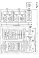
- Figure 1 is a schematic illustration of an example of a touch screen interface
- Figure 2 is a block diagram illustrating an example computing device 500 that is arranged for computing or storing a pulse rate value in accordance with the present disclosure
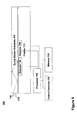
- Figure 3 is a block diagram illustrating an example computer program product 600 that is arranged to store instructions for determining a pulse rate value based on a detection signal in accordance with the present disclosure
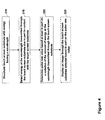
- Figure 4 is a flowchart of an example method of using a touch screen interface to determine a pulse rate value
- Figure 5 is a schematic illustration of an example of a touch screen interface that may be used to detect a blood oxygen level of a user.
- Figure 6 is a flowchart of an example method of using a touch screen interface to determine a blood oxygen level of a user, all arranged in accordance with at least some embodiments of the present disclosure.
- FIG 1 is a schematic illustration of an example of a touch screen interface 100 arranged in accordance with at least some embodiments of the present disclosure. An example of a cross-sectional portion of the touch screen interface 100 is also illustrated. Figure 1 is intended to be explanatory and is not drawn to scale.
- the touch screen interface 100 may include a touch screen substrate 105, a display 110, an optical energy source 115, one or more detectors 120, a processor 125, a memory 130 and optional output devices 135.
- the touch screen substrate 105 may be at least partially transparent such that light generated by a display 110 may be transmitted through the touch screen substrate 105.
- An example of a material that may be used to implement the touch screen substrate 105 is an acrylic pane.
- An optical energy source 115 may be positioned to illuminate the touch screen substrate 105.
- suitable optical energy sources may include light emitting diodes (LEDs) and lasers.
- LEDs light emitting diodes
- lasers lasers.
- a single optical energy source 115 is shown in Figure 1 , any number of optical energy sources may be provided and may be positioned along a length or width of the touch screen substrate 105.
- the optical energy source 115 may emit light having a wavelength that is absorbed differently by oxygenated and deoxygenated hemoglobin.
- pulse oximeters make use of 660 nm and 910 nm light.
- the oxygenated blood may reflect more of the 660 nm light than deoxygenated blood, while deoxygenated blood may reflect more of the 910 nm light than oxygenated blood.
- the optical energy source 115 may emit light having a wavelength of either 660 nm or 910 nm. Other wavelengths may also be used that are appropriate for pulse rate detection in other examples.
- Light emitted from the optical energy source 115 may be internally reflected within the touch screen substrate 105.
- light emitted from the optical energy source 115 may experience frustrated internal reflection and pass through the touch screen substrate 105.
- a detector 120 may sense the light transmitted through the touch screen substrate 115 caused in part by the contact.
- an array of detectors may be present adjacent to the touch screen substrate 105 to detect light transmitted through the touch screen substrate responsive to user contact.
- An array of detectors may be configured to detect a location of the contact.
- detectors may be provided around a perimeter of the touch screen substrate 105.
- the detector 120 may be positioned anywhere that it may receive energy reflected from the touch screen substrate 105.
- an array of such detectors may also be configured to provide location information about the contact.
- the detector 120 may not be configured to provide information about the location of the contact, and location information may be obtained by other techniques using resistive or capacitive sensors (not shown in Figure 1 ).
- the detector 120 is shown in the example of Figure 1 positioned beneath the touch screen substrate 105, in other examples, the detector 120 may be positioned in different locations.
- the touch screen substrate 105 is shown in a horizontal orientation in Figure 1 , in other examples the touch screen substrate 105 may be in a vertical orientation, and the detector 120 may be positioned on either side of the touch screen substrate. In other embodiments, the detector 120 may be positioned to receive energy transmitted through a length of the touch screen substrate 105, as indicated by the alternative positioning of the detector 120 in Figure 1 shown with dotted lines.
- An example of a detector that may be used to implement the detector 120 may be a charge-coupled device (CCD).
- CCD charge-coupled device
- one or more CCDs may be integrated into the display 110, however, in other examples the detector 120 may be separate from the display 110.
- filters may be included at any point between the touch screen substrate 105 and the detector 120, where each filter may be configured to block out energy of different wavelengths than the wavelength emitted by the optical energy source 115.
- the detector 120 may also be configured to detect a change in amplitude of the signal at the wavelength of light emitted by the energy source 115.
- the detected change in amplitude may correspond to a pulse rate associated with the user who contacted the touch screen substrate 105. Accordingly, the detector 120 may generate a detection signal corresponding to a pulse rate of a user, or a change in a pulse rate of a user.
- a processor 125 may be coupled to the detector 120.
- the processor 125 may be configured to receive the detection signal from the detector corresponding to an amount of energy received at the wavelength emitted by the optical energy source 115. By analyzing variations in the strength of the received signal over time, the processor 125 may determine a pulse rate value related to the pulse rate of the user who contacted the touch screen substrate 105.
- the processor 125 may also be coupled to the display 110 in some examples.
- the processor 125 may be configured to couple control signals to the display 110 for the display of images or selections to a viewer of the display 110. In other examples, however, a different processor may be used to control the display of images than the processor that is used to detect a pulse rate.
- the processor 125 may also be coupled to the detector 120 and arranged to receive location information about a contact from the user. In other examples, the processor 125 may be coupled to other sensors (not shown) and arranged to obtain location information.
- a memory 130 may be coupled to the processor 125.
- the memory 130 may be storing computer readable instructions, that, when executed, may cause the processor 125 to receive a signal from the detector 120 and determine a pulse rate value based on the changes in the received signal over time.
- the memory 130 may be encoded with instructions for computing the pulse rate value based on a detection signal or the memory may store a look-up table (LUT) for correlating measured signal changes associated with a pulse rate, for example.
- LUT look-up table
- the memory 130 may also be arranged to store values associated with the pulse rate (i.e., a pulse rate value) of the user. More than one pulse rate value may be stored in memory 130 when a user contacts a touch screen multiple times over the course of a given use.
- Detected changes in pulse rate values may be used by the processor 125 to present a graphical representation of one or more pulse rate values on the display 110 or other components of a device in which the touch screen interface 100 may be used. For example, a numerical display or one or more graphical plots may be generated and displayed on the display 110 containing information about one or more pulse rate values.
- the touch screen interface 100 shown in Figure 1 may be used to determine a pulse rate associated with a user contacting the touch screen substrate 105. Once a pulse rate value has been determined, the value may be output to one or more output devices 135, which may include another display or a network connection for communication to remote devices. In some examples, the determined pulse rate value may be displayed on the display 110. Based on the determined pulse rate value, the image displayed on the display 110 may be altered. Examples of applications, methods or processes for using the touch screen interface 100 will be discussed further below.
- FIG. 2 is a block diagram illustrating an example computing device 500 that is arranged for computing or storing a pulse rate value in accordance with the present disclosure.
- computing device 500 may include one or more processors 510 and system memory 520.
- a memory bus 530 may be used for communicating between the processor 510 and the system memory 520.
- processor 510 may be of any type including but not limited to a microprocessor ( ⁇ P), a microcontroller ( ⁇ C), a digital signal processor (DSP), or any combination thereof.
- Processor 510 may include one more levels of caching, such as a level one cache 511 and a level two cache 512, a processor core 513, and registers 514.
- An example processor core 513 may include an arithmetic logic unit (ALU), a floating point unit (FPU), a digital signal processing core (DSP Core), or any combination thereof.
- An example memory controller 515 may also be used with the processor 510, or in some implementations the memory controller 515 may be an internal part of the processor 510.
- system memory 520 may be of any type including but not limited to volatile memory (such as RAM), non-volatile memory (such as ROM, flash memory, etc.) or any combination thereof.
- System memory 520 may include an operating system 521, one or more applications 522, and program data 524.
- Application 522 may include a pulse rate value generation procedure that is arranged to determine a pulse rate value based on a detection signal received from a detector.
- the pulse rate value generation procedure may, for example, access a look-up table to determine a pulse rate value based on a received detection signal. Other procedures may also be used.
- Program data 524 may include pulse rate value data 525 that may be useful for determining a pulse rate value based on a received detection signal, such as a look-up table or experimental data.
- application 522 may be arranged to operate with program data 524 on an operating system 521 such that a pulse rate value is generated based on a detection signal. This described configuration is illustrated in Figure. 2 by those components within dashed line 501.
- Computing device 500 may have additional features or functionality, and additional interfaces to facilitate communications between the basic configuration 501 and any required devices and interfaces.
- a bus/interface controller 540 may be used to facilitate communications between the basic configuration 501 and one or more data storage devices 550 via a storage interface bus 541.
- the data storage devices 550 may be removable storage devices 551, non-removable storage devices 552, or a combination thereof.
- Examples of removable storage and non-removable storage devices include magnetic disk devices such as flexible disk drives and hard-disk drives (HDD), optical disk drives such as compact disk (CD) drives or digital versatile disk (DVD) drives, solid state drives (SSD), and tape drives to name a few.
- Example computer storage media may include volatile and nonvolatile, removable and non-removable media implemented in any method or technology for storage of information, such as computer readable instructions, data structures, program modules, or other data.
- Computer storage media includes, but is not limited to, RAM, ROM, EEPROM, flash memory or other memory technology, CD-ROM, digital versatile disks (DVD) or other optical storage, magnetic cassettes, magnetic tape, magnetic disk storage or other magnetic storage devices, or any other medium which may be used to store the desired information and which may be accessed by computing device 500. Any such computer storage media may be part of device 500.
- Computing device 500 may also include an interface bus 542 for facilitating communication from various interface devices (e.g., output interfaces, peripheral interfaces, and communication interfaces) to the basic configuration 501 via the bus/interface controller 540.
- Example output devices 560 include a graphics processing unit 561 and an audio processing unit 562, which may be configured to communicate to various external devices such as a display or speakers via one or more A/V ports 563.
- Example peripheral interfaces 570 include a serial interface controller 571 or a parallel interface controller 572, which may be configured to communicate with external devices such as input devices (e.g., keyboard, mouse, pen, voice input device, touch input device, etc.) or other peripheral devices (e.g., printer, scanner, etc.) via one or more I/O ports 573.
- An example communication device 580 includes a network controller 581, which may be arranged to facilitate communications with one or more other computing devices 590 over a network communication link via one or more communication ports 582.
- the network communication link may be one example of a communication media.
- Communication media may typically be embodied by computer readable instructions, data structures, program modules, or other data in a modulated data signal, such as a carrier wave or other transport mechanism, and may include any information delivery media.
- a "modulated data signal" may be a signal that has one or more of its characteristics set or changed in such a manner as to encode information in the signal.
- communication media may include wired media such as a wired network or direct-wired connection, and wireless media such as acoustic, radio frequency (RF), microwave, infrared (IR) and other wireless media.
- RF radio frequency
- IR infrared
- the term computer readable media as used herein may include both storage media and communication media.
- Computing device 500 may be implemented as a portion of a small-form factor portable (or mobile) electronic device such as a cell phone, a personal data assistant (PDA), a personal media player device, a wireless web-watch device, a personal headset device, an application specific device, or a hybrid device that include any of the above functions.
- a small-form factor portable (or mobile) electronic device such as a cell phone, a personal data assistant (PDA), a personal media player device, a wireless web-watch device, a personal headset device, an application specific device, or a hybrid device that include any of the above functions.
- PDA personal data assistant
- Computing device 500 may also be implemented as a personal computer including both laptop computer and non-laptop computer configurations.
- Figure 3 is a block diagram illustrating an example computer program product 600 that is arranged to store instructions for determining a pulse rate value based on a detection signal in accordance with the present disclosure.
- the computer readable medium 602 stores instructions 604 that may configure the processing unit to perform all or some of the processes previously described. These instructions may include, for example, one or more executable instructions for determining a pulse rate value based on a detection signal.
- the instructions may include accessing a look-up table to associate the detection signal with a pulse rate value.
- Figure 4 flowchart of an example method of using a touch screen interface to determine a pulse rate value.
- the example method may be utilized with the touch screen interface 100 described previously for Figure 1 , or other similarly arranged touch screen devices.
- the example method may include one or more of blocks 210, 215, 220 and 225.
- the touch screen substrate may be illuminated with optical energy having a wavelength that is appropriate for pulse detection. As described above, this wavelength may be 910 nm, 660 nm, or other wavelength of energy whose amplitude may vary in time with changes in a pulse rate.
- optical energy transmitted through the touch screen substrate at the requisite wavelength, at least in part due to the user contact with the substrate may be detected 215.
- a pulse rate may be determined based at least in part on variations in the detected energy over time.
- an image may then be displayed through the touch screen substrate that may be selected based in part on the determined pulse rate value.
- the image may be representative of the pulse rate value, or in some cases an image is displayed (such as a suggestion to a user) that is based on the pulse rate value, but not necessarily representative of the pulse rate value.
- the determined pulse rate value may in addition or alternatively be stored in memory, displayed elsewhere, or communicated to another device, or combinations thereof.
- Figure 5 is a schematic illustration of an example of a touch screen interface that may be used to detect a blood oxygen level of a user, in accordance with at least some embodiments of the present disclosure. An example of a cross-sectional portion of the touch screen interface 300 is also illustrated. Figure 5 is intended to be explanatory and is not drawn to scale.
- the touch screen interface 300 may have many similar elements to the example of the touch screen interface 100 of Figure 1 , and similar elements will not be described in detail again with reference to Figure 5 .
- the example of Figure 5 is configured for the detection of a blood oxygen level associated with a user by providing for the illumination of the touch screen substrate 105 with optical energy sources emitting at multiple wavelengths. Detectors may then be used to detect differences in the amount of energy transmitted through the touch screen substrate 105 at the different wavelengths.
- two optical energy sources 115 and 315 may be positioned effective to illuminate the touch screen substrate 105.
- An example of suitable optical energy sources may be light emitting diodes (LEDs).
- the two optical energy sources 115 and 315 may be arranged to emit energy at different wavelengths.
- Figure 5 illustrates single optical energy sources for emitting light at each wavelength
- any number of additional optical energy sources may be provided for emitting light at additional wavelengths, which may be positioned along a length or width of the touch screen substrate 105.
- a single optical energy source may be arranged to emit light at multiple wavelengths.
- the optical energy sources 115 and 315 may be arranged to emit light having a wavelength that is absorbed differently by oxygenated and deoxygenated hemoglobin. Pulse oximeters can make use of 660 nm and 910 nm light. Accordingly, the optical energy source 115 may be configured to emit energy having a wavelength of 660 nm while the light source 315 may be configured to emit energy having a wavelength of 910 nm.
- the oxygenated blood may reflect more of the 660 nm light than deoxygenated blood, while deoxygenated blood may reflect more of the 910 nm light than oxygenated blood. Other wavelengths may also be used that are appropriate for blood oxygen level detection in other examples.
- two detectors 120 and 320 may be provided to sense the light transmitted through the touch screen substrate 115 caused in part by the contact by the user.
- One of the detectors may be relatively insensitive to energy at one of the wavelengths emitted by the optical energy sources 115 and 315.
- an InGaAs CCD type of detector may be used as one of the detectors, which is sensitive to 910 nm light but relatively insensitive to 660 nm light. Accordingly, the detectors 120 and 320 may provide one or more detection signals that may be used to determine a difference in detected light of each wavelength.
- an array of detectors may be present adjacent to the touch screen substrate 105 to detect light transmitted through the touch screen substrate responsive to user contact. By providing an array of detectors, a location of the contact may also be determined. In other examples, detectors may be provided around a perimeter of the touch screen substrate 105. Generally, the detectors 120 and 320 may be positioned anywhere that they may receive energy transmitted through the touch screen substrate 105 and any number may be provided. In some additional examples, an array of such detectors may also be arranged to provide location information about the contact by the user.
- the detectors 120 and 320 may not be arranged to provide location information about the contact by the user, and location information may be obtained by resistive or capacitive sensors (not shown in Figure 5 ).
- a single detector may be used and later processing may separate out the wavelength components of the received signal. That is, a single detector may be provided that may be sensitive to both illumination wavelengths.
- the optical energy sources 115 and 315 may be pulsed such that the two energy sources may not illuminate the touch screen substrate simultaneously. In one example, the pulsing occurs on a millisecond timescale.
- the output of the single detector may then be synchronized to the energy source pulse information, and responses to the two different energy wavelengths identified and analyzed. That is, output of the single detector during illumination with the first wavelength may represent a response to the first wavelength, and output of the single detector during illumination with the second wavelength may represent a response to the second wavelength.
- the detectors 120 and 320 may also be positioned in different locations, such as positions effective to receive energy transmitted through a portion of the touch screen substrate 105.
- the processor 125 may be coupled to the detectors 120 and 130, and arranged to utilize signals received from the detectors 120 and 320 to determine a blood oxygen level of a user who made contact with the touch screen substrate 105.
- one of the detectors 120 and 320 may be relatively insensitive to at least one of the energy wavelengths emitted by the optical energy sources 115 and 315. Any suitable method for determining a blood oxygen level based on different absorption or reflectance of two energy wavelengths may then be implemented by the processor. By analyzing the different characteristics of energy emission at the different wavelengths (e.g., two or more wavelengths), the processor 125 may determine a blood oxygen level of the user who contacted the touch screen substrate 105.
- a memory 130 may be coupled to the processor 125.
- the memory 130 may be storing computer readable instructions, that, when executed, cause the processor 125 to receive signals from the detectors 120 and 320 and determine a blood oxygen level based on one or more differences in the received signals.
- the memory 130 may be encoded with instructions for computing the blood oxygen level or a look-up table (LUT) for correlating measured signal differences associated with a blood oxygen level, for example.
- the memory 130 may also be arranged to store a value associated with the blood oxygen level (i.e., a blood oxygen level value) of the user. More than one blood oxygen level value may be stored in memory 130, for example, when a user contacts a touch screen multiple times over the course of a given use.
- Detected changes in blood oxygen level values may be used by the processor 125 to present a graphical representation of one or more blood oxygen level values on the display 110 or other components of a device in which the touch screen interface 100 may be used. For example, a numerical display or one or more graphical plots may be generated and displayed on the display 110 containing information about one or more blood oxygen level values.
- the touch screen interface 300 shown in Figure 5 may be used to determine a blood oxygen level value associated with a user contacting the touch screen substrate 105. Once a blood oxygen level has been determined, the determined blood oxygen level (i.e., the blood oxygen level value) may be output to one or more output devices 135, which may include another display or a network connection for communication to remote devices. In some examples, the determined blood oxygen level may be displayed on the display 110. Based on the determined blood oxygen level, an image displayed on the display 110 may be altered. Examples of applications, methods or processes for using the touch screen interface 300 will be discussed further below. Additionally, the computing device 500 of Figure 2 may also be used with the touch screen interface of Figure 5 .
- Figure 6 is a flowchart of an example method of using a touch screen interface to determine blood oxygen level of a user, in accordance with at least some embodiments of the present disclosure.
- the example method may be utilized with the touch screen interface 300 previously described for Figure 5 , or other similarly arranged touch screen devices.
- the example method may include one or more of blocks 410,415, 420, and 425.
- the touch screen substrate may be illuminated with optical energy having at least a first wavelength and a second wavelength.
- these wavelengths may be 910 nm and 660 nm, or other wavelengths of energy that will be absorbed differently by oxygenated and deoxygenated blood.
- optical energy transmitted through the touch screen substrate at the requisite wavelengths, in part due to contact with the substrate may be detected.
- a blood oxygen level value may be determined based at least in part on differences between the amounts of energy at each of the various wavelengths detected over time.
- an image may then be displayed through the touch screen substrate that may be selected based in part on the determined blood oxygen level value.
- the determined blood oxygen level in addition or alternatively may be stored in memory, displayed elsewhere, or communicated to another device, or combinations thereof.
- touch screen interfaces may be configured to determine a blood oxygen level valueor a pulse rate value associated with a user in addition to sensing the location of a touch.
- touch screen interfaces may be provided that may determine both blood oxygen level values and pulse rate values corresponding to the user.
- the same processor may be used to calculate both blood oxygen level value and pulse rate value.
- different processors may be used.
- the term user is employed herein to refer to any object capable of having a pulse rate, blood oxygen level, or both, that may come into contact with the touch screen substrate.
- touch screen interfaces capable of measuring pulse rate, blood oxygen level, or both, may be employed in a variety of devices including, but not limited to, exercise equipment, appliances, auto or aeronautical control devices, phones, digital assistants, or kiosks.
- Touch screen interfaces capable of pulse rate, blood oxygen level, or both measurements may find a variety of uses.
- the measurements may be used as an indication of a user's health.
- a processor included in the machine may emit a control signal causing the machine to select or change a resistance or endurance value, or both, based on the measured pulse rate, blood oxygen level, or both.
- the processor 125 included in the touch screen interfaces 100 and 300 may be able to analyze changes in pulse rate over time. Increasing pulse rate may indicate frustration with the interface 100 or 300. Accordingly, the processor 125 may couple a control signal to the display 110 causing display of an apologetic message, or a recommendation to change the user's action.
- pulse oximetry techniques may be used to analyze other components of a user's blood, such as carbon monoxide.
- any number of wavelengths and suitable detectors may be used in conjunction with a touch screen interface to obtain any type of biological information suitable for measurement with pulse oximetry techniques.
- implementations may be in hardware, such as employed to operate on a device or combination of devices, for example, whereas other implementations may be in software and/or firmware.
- some implementations may include one or more articles, such as a storage medium or storage media.
- This storage media such as CD-ROMs, computer disks, flash memory, or the like, for example, may have instructions stored thereon, that, when executed by a system, such as a computer device, a computing system, a computing platform, or other system, for example, may result in execution of a processor in accordance with claimed subject matter, such as one of the implementations previously described, for example.
- a computing device may include one or more processing units or processors, one or more input/output devices, such as a display, a keyboard and/or a mouse, and one or more memories, such as static random access memory, dynamic random access memory, flash memory, and/or a hard drive.
- the implementer may opt for a mainly hardware and/or firmware vehicle; if flexibility is paramount, the implementer may opt for a mainly software implementation; or, yet again alternatively, the implementer may opt for some combination of hardware, software, and/or firmware.
- any two components so associated may also be viewed as being “operably connected”, or “operably coupled”, to each other to achieve the desired functionality, and any two components capable of being so associated may also be viewed as being “operably couplable”, to each other to achieve the desired functionality.
- operably couplable include but are not limited to physically mateable and/or physically interacting components and/or wirelessly interactable and/or wirelessly interacting components and/or logically interacting and/or logically interactable components.
- one or more components may be referred to herein as “configured to,” “configurable to,” “operable/operative to,” “adapted/adaptable,” “able to,” “conformable/conformed to,” etc.
- configured to can generally encompass active-state components and/or inactive-state components and/or standby-state components, unless context requires otherwise.
Landscapes
- Life Sciences & Earth Sciences (AREA)
- Engineering & Computer Science (AREA)
- Health & Medical Sciences (AREA)
- Physics & Mathematics (AREA)
- Animal Behavior & Ethology (AREA)
- General Health & Medical Sciences (AREA)
- Pathology (AREA)
- Biomedical Technology (AREA)
- Heart & Thoracic Surgery (AREA)
- Medical Informatics (AREA)
- Molecular Biology (AREA)
- Surgery (AREA)
- General Engineering & Computer Science (AREA)
- Biophysics (AREA)
- Public Health (AREA)
- Veterinary Medicine (AREA)
- Multimedia (AREA)
- Theoretical Computer Science (AREA)
- Human Computer Interaction (AREA)
- General Physics & Mathematics (AREA)
- Spectroscopy & Molecular Physics (AREA)
- Optics & Photonics (AREA)
- Measurement Of The Respiration, Hearing Ability, Form, And Blood Characteristics Of Living Organisms (AREA)
- Measuring Pulse, Heart Rate, Blood Pressure Or Blood Flow (AREA)
Applications Claiming Priority (1)
| Application Number | Priority Date | Filing Date | Title |
|---|---|---|---|
| US12/417,478 US8320985B2 (en) | 2009-04-02 | 2009-04-02 | Touch screen interfaces with pulse oximetry |
Publications (2)
| Publication Number | Publication Date |
|---|---|
| EP2237137A2 true EP2237137A2 (de) | 2010-10-06 |
| EP2237137A3 EP2237137A3 (de) | 2013-05-15 |
Family
ID=42269399
Family Applications (1)
| Application Number | Title | Priority Date | Filing Date |
|---|---|---|---|
| EP10154700.8A Withdrawn EP2237137A3 (de) | 2009-04-02 | 2010-02-25 | Berührungsbildschirmschnittstellen mit Pulsoximetrie |
Country Status (4)
| Country | Link |
|---|---|
| US (1) | US8320985B2 (de) |
| EP (1) | EP2237137A3 (de) |
| JP (1) | JP5216791B2 (de) |
| WO (1) | WO2010115051A2 (de) |
Cited By (3)
| Publication number | Priority date | Publication date | Assignee | Title |
|---|---|---|---|---|
| WO2012076683A1 (fr) * | 2010-12-09 | 2012-06-14 | Arthur Queval | Dispositif micro-fluidique pour l'analyse d'un échantillon de fluide |
| CN106264493A (zh) * | 2015-06-23 | 2017-01-04 | 三星电子株式会社 | 用于测量生物信号的触摸面板装置和方法 |
| WO2017053049A1 (en) * | 2015-09-21 | 2017-03-30 | Qualcomm Incorporated | System and method for obtaining vital measurements using a mobile device |
Families Citing this family (28)
| Publication number | Priority date | Publication date | Assignee | Title |
|---|---|---|---|---|
| CA3138078C (en) | 2007-10-02 | 2024-02-13 | Labrador Diagnostics Llc | Modular point-of-care devices and uses thereof |
| US8786575B2 (en) * | 2009-05-18 | 2014-07-22 | Empire Technology Development LLP | Touch-sensitive device and method |
| MX349288B (es) | 2011-01-21 | 2017-07-21 | Theranos Inc | Sistemas y metodos para maximizacion de uso de muestras. |
| CN102652669B (zh) * | 2011-03-04 | 2016-04-20 | 富泰华工业(深圳)有限公司 | 具有脉搏测量功能的触摸显示装置及脉搏测量方法 |
| US9268915B2 (en) * | 2011-09-25 | 2016-02-23 | Theranos, Inc. | Systems and methods for diagnosis or treatment |
| US20140170735A1 (en) | 2011-09-25 | 2014-06-19 | Elizabeth A. Holmes | Systems and methods for multi-analysis |
| US9664702B2 (en) | 2011-09-25 | 2017-05-30 | Theranos, Inc. | Fluid handling apparatus and configurations |
| US9632102B2 (en) | 2011-09-25 | 2017-04-25 | Theranos, Inc. | Systems and methods for multi-purpose analysis |
| US9619627B2 (en) | 2011-09-25 | 2017-04-11 | Theranos, Inc. | Systems and methods for collecting and transmitting assay results |
| US8475739B2 (en) | 2011-09-25 | 2013-07-02 | Theranos, Inc. | Systems and methods for fluid handling |
| US9250229B2 (en) | 2011-09-25 | 2016-02-02 | Theranos, Inc. | Systems and methods for multi-analysis |
| US9810704B2 (en) | 2013-02-18 | 2017-11-07 | Theranos, Inc. | Systems and methods for multi-analysis |
| US10012664B2 (en) | 2011-09-25 | 2018-07-03 | Theranos Ip Company, Llc | Systems and methods for fluid and component handling |
| US20130100043A1 (en) * | 2011-10-24 | 2013-04-25 | General Electric Company | Method for determining valid touch screen inputs |
| TWI474215B (zh) * | 2011-11-17 | 2015-02-21 | 原相科技股份有限公司 | 鍵盤模組及顯示系統 |
| DE112013000530T5 (de) * | 2012-01-10 | 2014-10-02 | Maxim Integrated Products, Inc. | Plusfrequenz- und Blutsauerstoff-Überwachungesystem |
| US9237082B2 (en) * | 2012-03-26 | 2016-01-12 | Hewlett Packard Enterprise Development Lp | Packet descriptor trace indicators |
| US9377900B1 (en) * | 2012-06-18 | 2016-06-28 | Amazon Technologies, Inc. | Optical touch sensor |
| TW201429447A (zh) * | 2013-01-29 | 2014-08-01 | Hon Hai Prec Ind Co Ltd | 具有心率監測功能的可擕式電子產品 |
| US9462979B2 (en) | 2013-12-06 | 2016-10-11 | Covidien Lp | Capacitance enhanced physiological measurements |
| US10076277B2 (en) | 2015-01-22 | 2018-09-18 | Covidien Lp | Pain level detection and characterization using capacitive sensors |
| CN104706334B (zh) | 2015-03-30 | 2017-08-11 | 京东方科技集团股份有限公司 | 一种具有健康监测功能的显示面板及显示装置 |
| US20170035333A1 (en) * | 2015-08-04 | 2017-02-09 | Osram Opto Semiconductors Gmbh | Apparatus for Measuring a Vital Function of a Living Creature |
| JP6763399B2 (ja) * | 2015-12-07 | 2020-09-30 | ソニー株式会社 | 脈拍計測素子、脈拍計測装置、および電子機器 |
| US20200272276A1 (en) * | 2019-02-22 | 2020-08-27 | Osram Opto Semiconductors Gmbh | Embedded Vital Sign Monitoring in Display Screens |
| CN112674764A (zh) * | 2020-12-17 | 2021-04-20 | 深圳市汇顶科技股份有限公司 | 血氧饱和度检测装置和电子设备 |
| WO2022126531A1 (zh) * | 2020-12-17 | 2022-06-23 | 深圳市汇顶科技股份有限公司 | 血氧饱和度检测装置和电子设备 |
| JP7852416B2 (ja) | 2022-07-19 | 2026-04-28 | オムロン株式会社 | 酸素飽和度測定装置及び酸素飽和度測定方法 |
Family Cites Families (31)
| Publication number | Priority date | Publication date | Assignee | Title |
|---|---|---|---|---|
| US4759369A (en) * | 1986-07-07 | 1988-07-26 | Novametrix Medical Systems, Inc. | Pulse oximeter |
| US5069214A (en) * | 1988-12-14 | 1991-12-03 | Gms Engineering Corporation | Flash reflectance oximeter |
| US5007423A (en) * | 1989-10-04 | 1991-04-16 | Nippon Colin Company Ltd. | Oximeter sensor temperature control |
| MX9702434A (es) * | 1991-03-07 | 1998-05-31 | Masimo Corp | Aparato de procesamiento de señales. |
| WO1995026013A1 (en) * | 1994-03-24 | 1995-09-28 | Minnesota Mining And Manufacturing Company | Biometric, personal authentication system |
| JPH07323162A (ja) * | 1994-06-01 | 1995-12-12 | Takara Co Ltd | 電子ゲーム装置 |
| JPH10108844A (ja) * | 1996-10-07 | 1998-04-28 | Matsushita Electric Ind Co Ltd | 情報処理装置 |
| US6337918B1 (en) * | 1996-11-04 | 2002-01-08 | Compaq Computer Corporation | Computer system with integratable touchpad/security subsystem |
| US6560352B2 (en) * | 1999-10-08 | 2003-05-06 | Lumidigm, Inc. | Apparatus and method of biometric identification or verification of individuals using optical spectroscopy |
| GB9725571D0 (en) * | 1997-12-04 | 1998-02-04 | Philips Electronics Nv | Electronic apparatus comprising fingerprint sensing devices |
| US6526315B1 (en) * | 2000-03-17 | 2003-02-25 | Tanita Corporation | Portable bioelectrical impedance measuring instrument |
| JP4660659B2 (ja) * | 2000-04-25 | 2011-03-30 | アークレイ株式会社 | 脈拍計およびこれを用いた脈拍計測システム |
| WO2001084482A2 (de) * | 2000-05-01 | 2001-11-08 | Delsy Electronic Components Ag | Vorrichtung zur eingabe von relativen koordinaten |
| US6606510B2 (en) * | 2000-08-31 | 2003-08-12 | Mallinckrodt Inc. | Oximeter sensor with digital memory encoding patient data |
| US20080009689A1 (en) * | 2002-04-09 | 2008-01-10 | Benaron David A | Difference-weighted somatic spectroscopy |
| US6707257B2 (en) * | 2002-08-08 | 2004-03-16 | Datex-Ohmeda, Inc. | Ferrite stabilized LED drive |
| FI115109B (fi) * | 2003-01-22 | 2005-02-28 | Nokia Corp | Tunnistusjärjestely ja tunnistusjärjestelyn käsittävä matkaviestin |
| US20050159656A1 (en) * | 2003-03-07 | 2005-07-21 | Hockersmith Linda J. | Method and apparatus for presentation of noninvasive glucose concentration information |
| WO2005001611A2 (en) * | 2003-05-30 | 2005-01-06 | Privaris, Inc. | A system and methods for assignation and use of media content subscription service privileges |
| CN1882279B (zh) * | 2003-11-18 | 2011-01-26 | 索尼株式会社 | 输入装置及输入方法以及电子设备 |
| GB2427825B (en) * | 2004-01-30 | 2007-08-01 | Univ Brown | Non-Invasive Spectroscopy Of Mammalian Tissues |
| CA2600938A1 (en) * | 2004-03-24 | 2005-10-06 | Andre Hoffmann | Identification, verification, and recognition method and system |
| US20060020216A1 (en) * | 2004-07-20 | 2006-01-26 | Sharp Kabushiki Kaisha | Medical information detection apparatus and health management system using the medical information detection apparatus |
| DK1951110T3 (da) * | 2005-10-24 | 2013-01-21 | Marcio Marc Aurelio Martins Abreu | Apparatur til måling af biologiske parametre |
| US20070265513A1 (en) * | 2006-05-11 | 2007-11-15 | Schenkman Kenneth A | Optical measurement of mitochondrial function in blood perfused tissue |
| US20080082004A1 (en) * | 2006-09-08 | 2008-04-03 | Triage Wireless, Inc. | Blood pressure monitor |
| JP2008130024A (ja) * | 2006-11-24 | 2008-06-05 | Oki Electric Ind Co Ltd | 生体情報取得装置 |
| JP2008242542A (ja) * | 2007-03-26 | 2008-10-09 | Yokogawa Electric Corp | 情報処理装置 |
| US8063889B2 (en) * | 2007-04-25 | 2011-11-22 | Honeywell International Inc. | Biometric data collection system |
| US20080285813A1 (en) * | 2007-05-14 | 2008-11-20 | Motorola, Inc. | Apparatus and recognition method for capturing ear biometric in wireless communication devices |
| US20090054751A1 (en) * | 2007-08-22 | 2009-02-26 | Bruce Babashan | Touchless Sensor for Physiological Monitor Device |
-
2009
- 2009-04-02 US US12/417,478 patent/US8320985B2/en not_active Expired - Fee Related
-
2010
- 2010-02-08 JP JP2010024987A patent/JP5216791B2/ja not_active Expired - Fee Related
- 2010-02-25 EP EP10154700.8A patent/EP2237137A3/de not_active Withdrawn
- 2010-04-01 WO PCT/US2010/029703 patent/WO2010115051A2/en not_active Ceased
Non-Patent Citations (1)
| Title |
|---|
| None |
Cited By (3)
| Publication number | Priority date | Publication date | Assignee | Title |
|---|---|---|---|---|
| WO2012076683A1 (fr) * | 2010-12-09 | 2012-06-14 | Arthur Queval | Dispositif micro-fluidique pour l'analyse d'un échantillon de fluide |
| CN106264493A (zh) * | 2015-06-23 | 2017-01-04 | 三星电子株式会社 | 用于测量生物信号的触摸面板装置和方法 |
| WO2017053049A1 (en) * | 2015-09-21 | 2017-03-30 | Qualcomm Incorporated | System and method for obtaining vital measurements using a mobile device |
Also Published As
| Publication number | Publication date |
|---|---|
| JP2010246894A (ja) | 2010-11-04 |
| WO2010115051A2 (en) | 2010-10-07 |
| EP2237137A3 (de) | 2013-05-15 |
| US20100256470A1 (en) | 2010-10-07 |
| JP5216791B2 (ja) | 2013-06-19 |
| US8320985B2 (en) | 2012-11-27 |
| WO2010115051A3 (en) | 2011-01-13 |
Similar Documents
| Publication | Publication Date | Title |
|---|---|---|
| US8320985B2 (en) | Touch screen interfaces with pulse oximetry | |
| US11607133B2 (en) | Biological component measuring apparatus and biological component measuring method | |
| US9427192B2 (en) | Touch-sensitive device and method | |
| JP4639321B2 (ja) | 生体情報測定装置 | |
| CN111954488B (zh) | 心血管健康监测装置 | |
| US11940388B2 (en) | Method for improving usability and accuracy for physiological measurement | |
| US12268499B2 (en) | System and method for robust pulse oximetry | |
| CN111134688B (zh) | 光学传感器、测量光信号的方法及估计血液浓度的装置 | |
| CN109549652B (zh) | 生物成分估计装置及其操作方法 | |
| KR102750435B1 (ko) | Ppg 센서, 이를 포함하는 전자 장치 및 이의 제어 방법 | |
| US20210386363A1 (en) | Portable Electronic Device Having an Integrated Bio-Sensor | |
| US20170112393A1 (en) | Measurement apparatus and measurement method | |
| JP2015212685A (ja) | センサおよび測定装置 | |
| CN113576474A (zh) | 电子设备及其血氧检测方法 | |
| US20250281129A1 (en) | Wearable Computing Device Having Optical Sensors to Indirectly Determine a Location of a Force Applied to a User Interface | |
| JPWO2019059061A1 (ja) | タッチパネル装置 | |
| JP2009201918A (ja) | 脈波検出装置 | |
| CN117761036A (zh) | 吸样异常检测方法及其检测装置、分析仪和电子设备 | |
| JP2013210943A (ja) | 座標入力装置、座標入力システム、及び座標入力方法 |
Legal Events
| Date | Code | Title | Description |
|---|---|---|---|
| PUAI | Public reference made under article 153(3) epc to a published international application that has entered the european phase |
Free format text: ORIGINAL CODE: 0009012 |
|
| AK | Designated contracting states |
Kind code of ref document: A2 Designated state(s): AT BE BG CH CY CZ DE DK EE ES FI FR GB GR HR HU IE IS IT LI LT LU LV MC MK MT NL NO PL PT RO SE SI SK SM TR |
|
| AX | Request for extension of the european patent |
Extension state: AL BA RS |
|
| PUAL | Search report despatched |
Free format text: ORIGINAL CODE: 0009013 |
|
| AK | Designated contracting states |
Kind code of ref document: A3 Designated state(s): AT BE BG CH CY CZ DE DK EE ES FI FR GB GR HR HU IE IS IT LI LT LU LV MC MK MT NL NO PL PT RO SE SI SK SM TR |
|
| AX | Request for extension of the european patent |
Extension state: AL BA RS |
|
| RIC1 | Information provided on ipc code assigned before grant |
Ipc: G06F 3/042 20060101AFI20130411BHEP |
|
| STAA | Information on the status of an ep patent application or granted ep patent |
Free format text: STATUS: THE APPLICATION IS DEEMED TO BE WITHDRAWN |
|
| 18D | Application deemed to be withdrawn |
Effective date: 20131116 |