EP2236972A2 - Fin for heat exchanger and heat exchanger using the fin - Google Patents
Fin for heat exchanger and heat exchanger using the fin Download PDFInfo
- Publication number
- EP2236972A2 EP2236972A2 EP10003134A EP10003134A EP2236972A2 EP 2236972 A2 EP2236972 A2 EP 2236972A2 EP 10003134 A EP10003134 A EP 10003134A EP 10003134 A EP10003134 A EP 10003134A EP 2236972 A2 EP2236972 A2 EP 2236972A2
- Authority
- EP
- European Patent Office
- Prior art keywords
- louvers
- fin
- flow direction
- air flow
- heat exchanger
- Prior art date
- Legal status (The legal status is an assumption and is not a legal conclusion. Google has not performed a legal analysis and makes no representation as to the accuracy of the status listed.)
- Granted
Links
Images


Classifications
-
- F—MECHANICAL ENGINEERING; LIGHTING; HEATING; WEAPONS; BLASTING
- F28—HEAT EXCHANGE IN GENERAL
- F28F—DETAILS OF HEAT-EXCHANGE AND HEAT-TRANSFER APPARATUS, OF GENERAL APPLICATION
- F28F1/00—Tubular elements; Assemblies of tubular elements
- F28F1/10—Tubular elements and assemblies thereof with means for increasing heat-transfer area, e.g. with fins, with projections, with recesses
- F28F1/12—Tubular elements and assemblies thereof with means for increasing heat-transfer area, e.g. with fins, with projections, with recesses the means being only outside the tubular element
- F28F1/126—Tubular elements and assemblies thereof with means for increasing heat-transfer area, e.g. with fins, with projections, with recesses the means being only outside the tubular element consisting of zig-zag shaped fins
- F28F1/128—Fins with openings, e.g. louvered fins
-
- F—MECHANICAL ENGINEERING; LIGHTING; HEATING; WEAPONS; BLASTING
- F28—HEAT EXCHANGE IN GENERAL
- F28F—DETAILS OF HEAT-EXCHANGE AND HEAT-TRANSFER APPARATUS, OF GENERAL APPLICATION
- F28F19/00—Preventing the formation of deposits or corrosion, e.g. by using filters or scrapers
- F28F19/006—Preventing deposits of ice
-
- F—MECHANICAL ENGINEERING; LIGHTING; HEATING; WEAPONS; BLASTING
- F28—HEAT EXCHANGE IN GENERAL
- F28F—DETAILS OF HEAT-EXCHANGE AND HEAT-TRANSFER APPARATUS, OF GENERAL APPLICATION
- F28F2215/00—Fins
- F28F2215/04—Assemblies of fins having different features, e.g. with different fin densities
-
- F—MECHANICAL ENGINEERING; LIGHTING; HEATING; WEAPONS; BLASTING
- F28—HEAT EXCHANGE IN GENERAL
- F28F—DETAILS OF HEAT-EXCHANGE AND HEAT-TRANSFER APPARATUS, OF GENERAL APPLICATION
- F28F2260/00—Heat exchangers or heat exchange elements having special size, e.g. microstructures
- F28F2260/02—Heat exchangers or heat exchange elements having special size, e.g. microstructures having microchannels
Definitions
- the present invention relates to a heat exchanger, and more particularly to a fin used with a heat exchanger.
- a heat exchanger is a commonly used component in refrigeration system and air conditioning system, and can be classified as a condenser, an evaporator and so on based on its functions. To improve the heat exchanging performance of a heat exchanger, among others, the heat exchanger is generally provided with a fin.
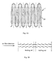
- Figs.1A and 1B show a conventional fin used with a heat exchanger
- Fig. 1A is a plan view of the fin
- Fig. 1B is a sectional view taken along line B-B in fig. 1A .
- a fin is made of a material with a high thermal conductivity such as aluminium alloy, and is formed by processing an aluminium alloy sheet.
- the fin contacts a surface of the heat exchanger, such as a surface of a flat tube, such that thermal conduction is achieved between the fin and the flat tube.
- the fin conducts heat exchange with external medium flowing over the fin, and thus achieving the heat exchange between the heat exchanger and the external medium.
- the fin 1 is formed with louvers 20, the louvers can be divided into two sets-a leading set and a trailing set in the flowing direction of the medium such as air, which is in the left-right direction in fig. 1B .
- the louver pattern of the conventional fin is completely symmetrical, specifically, the louver gap and tilt angle of the leading set of louvers are identical with the louver gap and tilt angle of the trailing set of louvers.
- the flowing air flows through the leading set of louvers first, and then the trailing set of louvers.
- the object of invention is to solve the problems associated with the conventional fin, and provides a fin for a heat exchanger which can improve the heat exchange performance of the heat exchanger, especially when frost forms on the fin.
- Another object of the invention is to provide a heat exchanger provided with a fin in accordance with the invention.
- a fin for a heat exchanger the fin is formed with louvers, and air, which is used as heat exchange medium, successively flows through the louvers when the heat exchanger operates.
- the louver gap of the louvers changes in the air flow direction, such that a louver gap at a certain portion of the louvers matches with a amount of frost formed at said portion.
- a louver gap located upstream in the air flow direction is larger than or equal to an adjacent downstream louver gap, and at least one or more of the louver gaps is/are larger than an adjacent downstream louver gap.
- the louver gap of the louvers decreases continuously in the air flow direction.
- the louvers have a constant tilt angle, and the pitch of the louvers decreases continuously in the air flow direction.
- the louvers have a constant pitch, and the tilt angle of the louvers decreases continuously in the air flow direction.
- the louvers is divided into a number of sets in the air flow direction, each set of louvers has a constant louver gap, the louver gap of a set which is located upstream in the air flow direction is larger than the louver gap of an adjacent downstream set.
- the sets have a uniform tilt angle, and the pitch of a set which is located upstream in the air flow direction is larger than the pitch of an adjacent downstream set.
- the sets have a uniform pitch, and the tilt angle of a set which is located upstream in the air flow direction is larger than the tilt angle of an adjacent downstream set.
- the louvers are divided into a leading set which is located upstream and a trailing set which is located downstream in the air flow direction.
- a heat exchanger which comprises a fin as defined in the first aspect of the invention.
- the heat exchanger is a microchannel heat exchanger.
- the louver gap at a certain portion of the louvers is made to match with the amount of frost formed at that portion, such that a sufficient space is still left between adjacent louvers for the air to flow through.
- the wind resistance will not increase substantially to decrease the amount of air flowing through, and thus the heat exchange performance of the fin can be utilized completely.
- the fin used for a heat exchanger according to the invention will be described in detail below. It should be noted that the embodiments of the invention are only illustrative, they are only used to describe the principle of the invention but not to limit the invention. Furthermore, it is obvious to one skilled in the art that the fin according to the invention can be used with various heat exchangers which use a fin, including a microchannel heat exchanger.
- the area between two adjacent louvers, through which air flows, depends on a distance between the two adjacent louvers measured in a line perpendicular to the two louvers, i.e. the louver gap.
- the present invention takes into consideration the difference of the frost-forming condition between the leading set and the trailing set of the louvers, and the difference of the frost-forming condition at different portions of the leading set and the trailing set in the air flow direction, and provides a louver pattern that can prevent the heat exchanging performance of a heat exchanger from degrading when frost forms on the fin.
- fig. 2 shows the pattern of louvers in accordance with the first embodiment of the invention.
- the fin in accordance with the first embodiment of the invention adopts a solution as follows.
- the pitch of the louvers decreases gradually in the air flow direction, and the tilt angle of the louvers remains constant, such that the louver gap d of the louvers decreases gradually in the air flow direction, i.e. d1>d2>d3>d4>d5>d6>d7>d8, as schematically shown in fig.2 .
- the louver gap at different portions of the louvers is made to match with the amount of the frost formed there: the frost forms more at a portion located upstream relative to the air flow direction, and accordingly the louver gap between adjacent louvers at that portion is relatively large; and the frost forms less at a portion located downstream relative to the air flow direction, and accordingly the louver gap between adjacent louvers at that portion is relatively small.
- the louver gap between adjacent louvers is made large at the portion of the louvers where the frost forms more, therefore can accommodate more frost. Accordingly, even at the portion where the frost forms more, enough space is still left between adjacent louvers for the air to flow through. Since the amount of frost formed on the louvers decreases gradually in the air flow direction, the louver gap of the louvers decreases gradually, as a result, a suitable density of the louvers is maintained without influencing the amount of the air flowing through the louvers. Therefore, with the fin in accordance with the first embodiment of the invention, consideration is given to both the density of the louvers and the area, through which air flows, at various portions of the louvers when the frost forms. As a result, the heat exchange performance of the fin is completely utilized in the situation where the frost forms on the fin.
- Fig.3 shows the fin in accordance with the second embodiment of the invention.
- the fin in accordance with the second embodiment of the invention adopts a solution as follows.
- the pitch between adjacent louvers in the leading set of the louvers is set to a first pitch
- the pitch between the adjacent louvers in the trailing set of louvers is set to a second pitch which is smaller the first pitch
- the tilt angle of all the louvers remains constant, such that the leading set of louvers has a first uniform louver gap D1, and the trailing set of louvers has a second uniform louver gap D2, and the first louver gap D1 is larger than the second louver gap D2, as shown in fig. 3 .
- the louver gap of the leading set of louvers and the louver gap of the trailing set of louvers are made to match respectively with the amount of frost formed at the leading set of louvers and the trailing set of louvers: the frost forms more at the leading set of louvers, and accordingly the louver gap of the leading set of louvers is relatively large; and the frost forms less at the trailing set of louvers, and accordingly the louver gap of the trailing set of louvers is relatively small.
- louver gap is relatively large at the leading set of louvers where the frost forms more, and thus can accommodate more frost. Accordingly, even at the leading set of louvers where the frost forms more, enough space is still left between adjacent louvers for the air to flow through.
- the fin in accordance with the second embodiment of the invention although a relatively large louver gap is provided at the leading set, which results in a lower heat exchange performance in the leading set than in the trailing set, the amount of air flowing through will not be substantially decreased when frost forms because the space for accommodating the frost is increased at the leading set.
- the trailing set since less frost is formed there, a suitable density of louvers is maintained by adopting a small gap. Therefore, with the fin in accordance with the second embodiment of the invention, the heat transfer performance of both the leading set and the trailing set are completely utilized. And furthermore, since the leading set of louvers has a uniform louver gap and so does the trailing set of louvers, the fin can be relatively easily manufactured as compared with the fin of the first embodiment.
- Fig.4 shows the fin in accordance with the third embodiment of the invention.
- the fin in accordance with the third embodiment of the invention adopts a solution as follows.
- the tilt angle ⁇ of the louvers is made to decrease gradually in the air flow direction, i.e. ⁇ 1> ⁇ 2> ⁇ 3> ⁇ 4> ⁇ 5> ⁇ 6> ⁇ 7> ⁇ 8 and the louver pitch between the adjacent louvers of the louvers remains constant, so that the louver gap between the adjacent louvers of the louvers decreases gradually, as shown in fig.4 .
- the louver gap between adjacent louvers at different portions of the louvers is made to match with the amount of frost formed at those different portions: the frost forms more at a portion located forwardly relative to the air flow direction, and accordingly the tilt angle of the louvers at that portion is relatively large, and thus resulting in a relatively large louver gap; and the frost forms less at a portion located rearward relative to the air flow direction, and accordingly the tilt angle of the louvers at that portion is relatively small, and thus resulting in a relatively small louver gap.
- the louver gap between adjacent louvers is made relatively large at the portion of the louvers where the frost forms more, therefore can accommodate more frost. Accordingly, even at the portion where the frost forms more, enough space is still left between the adjacent louvers for the air to flow through. And furthermore, at the leading set of the louvers, the density of the louvers does not decrease even if a large louver gap is provided there.
- consideration is given to both the density of the louvers and the area, through which the air flows, at various portions of the louvers when the frost forms, and thus the heat transfer performance of the fin is completely utilized.
- Fig.4 shows the fin in accordance with the fourth embodiment of the invention.
- the fin in accordance with the fourth embodiment of the invention adopts a solution as follows.
- the tilt angle of the louvers in the leading set of louvers is set to a first tilt angle ⁇ 1
- the angle of the louvers in the trailing set of louvers is set to a second tilt angle ⁇ 2 which is smaller the first tilt angle ⁇ 1
- a uniform pitch is provided between adjacent louvers, such that the leading set of louvers have a first uniform louver gap and the trailing set of louvers have a second uniform louver gap, and the first louver gap is larger than the second louver gap, as shown in fig. 5 .
- the louver gap of the leading set of louvers and the louver gap of the trailing set of louvers are made to match respectively with the amount of frost formed at the leading set and the trailing set: the frost forms more at the leading set of louvers, and accordingly the louver gap of the leading set of louvers is relatively large; and the frost forms less at the trailing set of louvers, and accordingly the louver gap of the trailing set of louvers is relatively small.
- louver gap of the louvers is relatively large at the leading set of louvers where the frost forms more, and thus can accommodate more frost. Accordingly, even at the leading set of louvers where the frost forms more, enough space is still left between adjacent louvers for the air to flow through.
- a fin in accordance with the fourth embodiment of the invention at the leading set, since the louvers have a relatively large tilt angle, and the density of the louvers does not decrease even if a large louver gap is provided, a good heat exchange performance is achieved. And furthermore, since a large louver gap is provided at the leading set, the amount of air flowing through will not be substantially decreased when frost forms, and thus the heat exchange performance of the fin is completely utilized. And furthermore, with the fin in accordance with the fourth embodiment, since the leading set of louvers has a uniform tile angle and so does the trailing set of louvers, the fin can be relatively easily manufactured as compared with the fin of the third embodiment.
- the louver gap between adjacent louvers at a certain portion of the louvers is made to match with the amount of frost formed there, such that a sufficient space is still left between any two adjacent louvers for the air to flow through when frost forms on the louvers.
- the wind resistance will not increase substantially to decrease the amount of air flowing through, thus the heat exchange performance of the fin is utilized completely.
- the louvers are divided into a leading set and a trailing set in the air flow direction, and each set has a uniform louver gap.
- the present invention is not limited to this, and various changes can be made based on the principle of the invention e.g.:
- the louver gap between adjacent louvers is changed by changing only the pitch of the louvers while the tilt angle of the louvers is kept constant; and in the above third and fourth embodiments, the louver gap between adjacent louvers is changed by changing only the tilt angle of the louvers while the pitch of the louvers is kept constant.
- the louver gap between adjacent louvers can be changed by changing both the pitch of the louvers and the tilt angle of the louvers at the same time; or in the case that the fin is divided into a leading set and a trailing set in the air flow direction, in one of the leading set and the trailing set, the louver gap between adjacent louvers is changed by changing one of the pitch of the louvers and the tilt angle of the louvers; while in the other of the leading set and the trailing set, the louver gap between adjacent louvers is changed by changing the other of the pitch of the louvers and the tilt angle of the louvers. Therefore, the louver gap can be changed in any way by taking the pitch of the louvers and the tilt angle of the louvers as parameters, if only the gap between adjacent louvers at a creation portion of the louvers can be made to match with the amount of frost formed there.
- louvers are divided into a leading set and a trailing set in the air flow direction in the above embodiments, but it is obvious to one skilled in the art that the louvers can be divided into a number of sets in the air flow direction in some other ways.
Landscapes
- Engineering & Computer Science (AREA)
- Physics & Mathematics (AREA)
- Thermal Sciences (AREA)
- Mechanical Engineering (AREA)
- General Engineering & Computer Science (AREA)
- Geometry (AREA)
- Air-Flow Control Members (AREA)
- Heat-Exchange Devices With Radiators And Conduit Assemblies (AREA)
Abstract
Description
- The present invention relates to a heat exchanger, and more particularly to a fin used with a heat exchanger.
- A heat exchanger is a commonly used component in refrigeration system and air conditioning system, and can be classified as a condenser, an evaporator and so on based on its functions. To improve the heat exchanging performance of a heat exchanger, among others, the heat exchanger is generally provided with a fin.
-
Figs.1A and 1B show a conventional fin used with a heat exchanger,Fig. 1A is a plan view of the fin, andFig. 1B is a sectional view taken along line B-B infig. 1A . - A fin is made of a material with a high thermal conductivity such as aluminium alloy, and is formed by processing an aluminium alloy sheet. In the operation state of the heat exchanger, the fin contacts a surface of the heat exchanger, such as a surface of a flat tube, such that thermal conduction is achieved between the fin and the flat tube. And the fin conducts heat exchange with external medium flowing over the fin, and thus achieving the heat exchange between the heat exchanger and the external medium.
- As shown in
figs.1A and 1B , the fin 1 is formed withlouvers 20, the louvers can be divided into two sets-a leading set and a trailing set in the flowing direction of the medium such as air, which is in the left-right direction infig. 1B . The louver pattern of the conventional fin is completely symmetrical, specifically, the louver gap and tilt angle of the leading set of louvers are identical with the louver gap and tilt angle of the trailing set of louvers. During the operation of the heat exchanger, the flowing air flows through the leading set of louvers first, and then the trailing set of louvers. - When a microchannel heat exchanger is used in an outdoor unit of a heat pump, if the outdoor atmospheric temperature is low, frost will form on the external surface of the heat exchanger and on the fin. The frost forms faster and more on the leading set, while the frost forms slower and less on the trailing set. If the louver gap and tilt angle of the leading set are identical with the louver gap and tilt angle of the trailing set, since the frost forms faster and more on the leading set, the area of the gap between adjacent louvers of the leading set of the fin, through which the air flows, will decrease. As a result, the wind resistance increases at the leading set and the amount of air flowing through decreases, resulting in the degradation of the hear exchange performance of the heat exchanger. Thus, the heat exchange performance of the microchannel heat exchanger is not completely utilized.
- In consideration of the problems associated with the conventional fin, there is a need for further improving the heat exchange performance of the heat exchanger.
- The object of invention is to solve the problems associated with the conventional fin, and provides a fin for a heat exchanger which can improve the heat exchange performance of the heat exchanger, especially when frost forms on the fin.
- Another object of the invention is to provide a heat exchanger provided with a fin in accordance with the invention.
- To achieve the above objects, according to a first aspect of the invention, there is provided a fin for a heat exchanger, the fin is formed with louvers, and air, which is used as heat exchange medium, successively flows through the louvers when the heat exchanger operates. The louver gap of the louvers changes in the air flow direction, such that a louver gap at a certain portion of the louvers matches with a amount of frost formed at said portion.
- Preferably, a louver gap located upstream in the air flow direction is larger than or equal to an adjacent downstream louver gap, and at least one or more of the louver gaps is/are larger than an adjacent downstream louver gap.
- Preferably, the louver gap of the louvers decreases continuously in the air flow direction.
- Preferably, the louvers have a constant tilt angle, and the pitch of the louvers decreases continuously in the air flow direction.
- Preferably, the louvers have a constant pitch, and the tilt angle of the louvers decreases continuously in the air flow direction.
- Preferably, the louvers is divided into a number of sets in the air flow direction, each set of louvers has a constant louver gap, the louver gap of a set which is located upstream in the air flow direction is larger than the louver gap of an adjacent downstream set.
- Preferably, the sets have a uniform tilt angle, and the pitch of a set which is located upstream in the air flow direction is larger than the pitch of an adjacent downstream set.
- Preferably, the sets have a uniform pitch, and the tilt angle of a set which is located upstream in the air flow direction is larger than the tilt angle of an adjacent downstream set.
- Preferably, the louvers are divided into a leading set which is located upstream and a trailing set which is located downstream in the air flow direction.
- According to a second aspect of the invention, there is provided a heat exchanger which comprises a fin as defined in the first aspect of the invention.
- Preferably, the heat exchanger is a microchannel heat exchanger.
- With the technical solution of the invention, the louver gap at a certain portion of the louvers is made to match with the amount of frost formed at that portion, such that a sufficient space is still left between adjacent louvers for the air to flow through. As a result, the wind resistance will not increase substantially to decrease the amount of air flowing through, and thus the heat exchange performance of the fin can be utilized completely.
- The invention will be described in detail below with reference to the accompanying drawings, in which:
-
Fig. 1A is a plan view showing the structure of a conventional fin used with a heat exchanger; -
Fig. 1B is a sectional view taken along line A-A infig.1A , showing the pattern of conventional louvers; -
Fig. 2 is a view similar tofig.1B , showing the pattern of louvers in accordance with a first embodiment of the invention; -
Fig. 3 is a view similar tofig.2 , showing the pattern of louvers in accordance with a second embodiment of the invention; -
Fig. 4 is a view similar tofig.2 , showing the pattern of louvers in accordance with a third embodiment of the invention; and -
Fig. 5 is a view similar tofig.3 , showing the pattern of louvers in accordance with a fourth embodiment of the invention. - The fin used for a heat exchanger according to the invention will be described in detail below. It should be noted that the embodiments of the invention are only illustrative, they are only used to describe the principle of the invention but not to limit the invention. Furthermore, it is obvious to one skilled in the art that the fin according to the invention can be used with various heat exchangers which use a fin, including a microchannel heat exchanger.
- In the following description, components similar to those in the prior art will be designated with the same reference numerals and their detailed description will be omitted.
- The area between two adjacent louvers, through which air flows, depends on a distance between the two adjacent louvers measured in a line perpendicular to the two louvers, i.e. the louver gap. The present invention takes into consideration the difference of the frost-forming condition between the leading set and the trailing set of the louvers, and the difference of the frost-forming condition at different portions of the leading set and the trailing set in the air flow direction, and provides a louver pattern that can prevent the heat exchanging performance of a heat exchanger from degrading when frost forms on the fin.
- Reference is now made to
fig. 2 , which shows the pattern of louvers in accordance with the first embodiment of the invention. In consideration of the fact that the amount of frost formed on the various portions of the louvers decreases gradually in the air flow direction when the outdoor atmospheric temperature is low, the fin in accordance with the first embodiment of the invention adopts a solution as follows. - The pitch of the louvers decreases gradually in the air flow direction, and the tilt angle of the louvers remains constant, such that the louver gap d of the louvers decreases gradually in the air flow direction, i.e. d1>d2>d3>d4>d5>d6>d7>d8, as schematically shown in
fig.2 . With such a pattern, the louver gap at different portions of the louvers is made to match with the amount of the frost formed there: the frost forms more at a portion located upstream relative to the air flow direction, and accordingly the louver gap between adjacent louvers at that portion is relatively large; and the frost forms less at a portion located downstream relative to the air flow direction, and accordingly the louver gap between adjacent louvers at that portion is relatively small. - With a louver pattern mentioned above, the louver gap between adjacent louvers is made large at the portion of the louvers where the frost forms more, therefore can accommodate more frost. Accordingly, even at the portion where the frost forms more, enough space is still left between adjacent louvers for the air to flow through. Since the amount of frost formed on the louvers decreases gradually in the air flow direction, the louver gap of the louvers decreases gradually, as a result, a suitable density of the louvers is maintained without influencing the amount of the air flowing through the louvers. Therefore, with the fin in accordance with the first embodiment of the invention, consideration is given to both the density of the louvers and the area, through which air flows, at various portions of the louvers when the frost forms. As a result, the heat exchange performance of the fin is completely utilized in the situation where the frost forms on the fin.
-
Fig.3 shows the fin in accordance with the second embodiment of the invention. In consideration of the fact that the amount of frost formed on the various portions of the louvers decreases gradually in the air flow direction, the fin in accordance with the second embodiment of the invention adopts a solution as follows. - The pitch between adjacent louvers in the leading set of the louvers is set to a first pitch, the pitch between the adjacent louvers in the trailing set of louvers is set to a second pitch which is smaller the first pitch, and the tilt angle of all the louvers remains constant, such that the leading set of louvers has a first uniform louver gap D1, and the trailing set of louvers has a second uniform louver gap D2, and the first louver gap D1 is larger than the second louver gap D2, as shown in
fig. 3 . With such a pattern, the louver gap of the leading set of louvers and the louver gap of the trailing set of louvers are made to match respectively with the amount of frost formed at the leading set of louvers and the trailing set of louvers: the frost forms more at the leading set of louvers, and accordingly the louver gap of the leading set of louvers is relatively large; and the frost forms less at the trailing set of louvers, and accordingly the louver gap of the trailing set of louvers is relatively small. - With a louver pattern mentioned above, since the louver gap is relatively large at the leading set of louvers where the frost forms more, and thus can accommodate more frost. Accordingly, even at the leading set of louvers where the frost forms more, enough space is still left between adjacent louvers for the air to flow through.
- With the fin in accordance with the second embodiment of the invention, although a relatively large louver gap is provided at the leading set, which results in a lower heat exchange performance in the leading set than in the trailing set, the amount of air flowing through will not be substantially decreased when frost forms because the space for accommodating the frost is increased at the leading set. As for the trailing set, since less frost is formed there, a suitable density of louvers is maintained by adopting a small gap. Therefore, with the fin in accordance with the second embodiment of the invention, the heat transfer performance of both the leading set and the trailing set are completely utilized. And furthermore, since the leading set of louvers has a uniform louver gap and so does the trailing set of louvers, the fin can be relatively easily manufactured as compared with the fin of the first embodiment.
-
Fig.4 shows the fin in accordance with the third embodiment of the invention. In consideration of the fact that the amount of the frost formed on the various portions of the louvers decreases gradually in the air flow direction, the fin in accordance with the third embodiment of the invention adopts a solution as follows. - The tilt angle α of the louvers is made to decrease gradually in the air flow direction, i.e. α1>α2>α3>α4>α5>α6>α7>α8 and the louver pitch between the adjacent louvers of the louvers remains constant, so that the louver gap between the adjacent louvers of the louvers decreases gradually, as shown in
fig.4 . With such a pattern, the louver gap between adjacent louvers at different portions of the louvers is made to match with the amount of frost formed at those different portions: the frost forms more at a portion located forwardly relative to the air flow direction, and accordingly the tilt angle of the louvers at that portion is relatively large, and thus resulting in a relatively large louver gap; and the frost forms less at a portion located rearward relative to the air flow direction, and accordingly the tilt angle of the louvers at that portion is relatively small, and thus resulting in a relatively small louver gap. - With a louver pattern mentioned above, similar to the first embodiment, the louver gap between adjacent louvers is made relatively large at the portion of the louvers where the frost forms more, therefore can accommodate more frost. Accordingly, even at the portion where the frost forms more, enough space is still left between the adjacent louvers for the air to flow through. And furthermore, at the leading set of the louvers, the density of the louvers does not decrease even if a large louver gap is provided there. As a result, with the fin in accordance with the third embodiment of the invention, consideration is given to both the density of the louvers and the area, through which the air flows, at various portions of the louvers when the frost forms, and thus the heat transfer performance of the fin is completely utilized.
-
Fig.4 shows the fin in accordance with the fourth embodiment of the invention. In consideration of the fact that the amount of frost formed on the various portions of the louvers decreases gradually along the air flow direction, the fin in accordance with the fourth embodiment of the invention adopts a solution as follows. - The tilt angle of the louvers in the leading set of louvers is set to a first tilt angle α1, the angle of the louvers in the trailing set of louvers is set to a second tilt angle α2 which is smaller the first tilt angle α1, and a uniform pitch is provided between adjacent louvers, such that the leading set of louvers have a first uniform louver gap and the trailing set of louvers have a second uniform louver gap, and the first louver gap is larger than the second louver gap, as shown in
fig. 5 . With such a pattern, the louver gap of the leading set of louvers and the louver gap of the trailing set of louvers are made to match respectively with the amount of frost formed at the leading set and the trailing set: the frost forms more at the leading set of louvers, and accordingly the louver gap of the leading set of louvers is relatively large; and the frost forms less at the trailing set of louvers, and accordingly the louver gap of the trailing set of louvers is relatively small. - With a louver pattern mentioned above, since the louver gap of the louvers is relatively large at the leading set of louvers where the frost forms more, and thus can accommodate more frost. Accordingly, even at the leading set of louvers where the frost forms more, enough space is still left between adjacent louvers for the air to flow through.
- With a fin in accordance with the fourth embodiment of the invention, at the leading set, since the louvers have a relatively large tilt angle, and the density of the louvers does not decrease even if a large louver gap is provided, a good heat exchange performance is achieved. And furthermore, since a large louver gap is provided at the leading set, the amount of air flowing through will not be substantially decreased when frost forms, and thus the heat exchange performance of the fin is completely utilized. And furthermore, with the fin in accordance with the fourth embodiment, since the leading set of louvers has a uniform tile angle and so does the trailing set of louvers, the fin can be relatively easily manufactured as compared with the fin of the third embodiment.
- It can be seen from above that, according to the invention, the louver gap between adjacent louvers at a certain portion of the louvers is made to match with the amount of frost formed there, such that a sufficient space is still left between any two adjacent louvers for the air to flow through when frost forms on the louvers. As a result, the wind resistance will not increase substantially to decrease the amount of air flowing through, thus the heat exchange performance of the fin is utilized completely.
- The embodiments of the invention have been described above in connection with the drawings. It should be appreciated by one skilled in the art that the embodiments are only exemplary but not limitative, various modifications are possible without departing from the spirit and scope of the invention.
- In the above second and fourth embodiments, the louvers are divided into a leading set and a trailing set in the air flow direction, and each set has a uniform louver gap. However, the present invention is not limited to this, and various changes can be made based on the principle of the invention e.g.:
- 1. One or both of the leading set and trailing set can be further divided into several sub-sets in the air flow direction, and each sub-set has a uniform louver gap, the adjacent sub-sets have a different louver gap.
- 2. The louver gap of one of the leading set and the trailing set decreases gradually in the air flow direction.
- 3. One or both of the leading set and trailing set can be further divided into e.g. a first sub-set and a second sub-set in the air flow direction one of the first and second sub-sets has a uniform louver gap, and the other of the first and second sub-sets has a louver gap which decreases gradually in the air flow direction.
- In the above first and second embodiments, the louver gap between adjacent louvers is changed by changing only the pitch of the louvers while the tilt angle of the louvers is kept constant; and in the above third and fourth embodiments, the louver gap between adjacent louvers is changed by changing only the tilt angle of the louvers while the pitch of the louvers is kept constant. However, the invention is not limited to this, the louver gap between adjacent louvers can be changed by changing both the pitch of the louvers and the tilt angle of the louvers at the same time; or in the case that the fin is divided into a leading set and a trailing set in the air flow direction, in one of the leading set and the trailing set, the louver gap between adjacent louvers is changed by changing one of the pitch of the louvers and the tilt angle of the louvers; while in the other of the leading set and the trailing set, the louver gap between adjacent louvers is changed by changing the other of the pitch of the louvers and the tilt angle of the louvers. Therefore, the louver gap can be changed in any way by taking the pitch of the louvers and the tilt angle of the louvers as parameters, if only the gap between adjacent louvers at a creation portion of the louvers can be made to match with the amount of frost formed there.
- And furthermore, for the sake of facilitating description, the louvers are divided into a leading set and a trailing set in the air flow direction in the above embodiments, but it is obvious to one skilled in the art that the louvers can be divided into a number of sets in the air flow direction in some other ways.
Claims (11)
- A fin for a heat exchanger, said fin being formed with louvers, and air, which is used as heat exchange medium, successively flowing through said louvers when the heat exchanger operates,
wherein the louver gap of the louvers changes in the air flow direction, such that a louver gap at a certain portion of the louvers matches with a amount of frost formed at said portion. - The fin as claimed in claim 1, wherein a louver gap located upstream in the air flow direction is larger than or equal to an adjacent downstream louver gap, and at least one or more of the louver gaps is/are larger than the an adjacent downstream louver gap.
- The fin as claimed in claim 2, wherein the louver gap of said louvers decreases continuously in the air flow direction.
- The fin as claimed in claim 3, wherein said louvers have a constant tilt angle, and the pitch of the louvers decreases continuously in the air flow direction.
- The fin as claimed in claim 3, wherein said louvers have a constant pitch, and the tilt angle of the louvers decreases continuously in the air flow direction.
- The fin as claimed in claim 2, wherein said louvers is divided into a number of sets in the air flow direction, each set of louvers has a constant louver gap, the louver gap of a set which is located upstream in the air flow direction is larger than the louver gap of an adjacent downstream set.
- The fin as claimed in claim 6, wherein said sets have a uniform tilt angle, and the pitch of a set which is located upstream in the air flow direction is larger than the pitch of an adjacent downstream set.
- The fin as claimed in claim 6, wherein said sets have a uniform pitch, and the tilt angle of a set which is located upstream in the air flow direction is larger than the tilt angle of an adjacent downstream set.
- The fin as claimed in any one of claims 6-8, wherein said louvers are divided into a leading set which is located upstream and a trailing set which is located downstream in the air flow direction.
- A heat exchanger which comprises a fin as claimed in any one of claims 1-9.
- The heat exchanger as claimed in claim 10, wherein said heat exchanger is a microchannel heat exchanger.
Applications Claiming Priority (1)
| Application Number | Priority Date | Filing Date | Title |
|---|---|---|---|
| CN200910119662XA CN101846479B (en) | 2009-03-25 | 2009-03-25 | Fin for heat exchanger and heat exchanger using same |
Publications (3)
| Publication Number | Publication Date |
|---|---|
| EP2236972A2 true EP2236972A2 (en) | 2010-10-06 |
| EP2236972A3 EP2236972A3 (en) | 2014-03-05 |
| EP2236972B1 EP2236972B1 (en) | 2020-09-30 |
Family
ID=42263709
Family Applications (1)
| Application Number | Title | Priority Date | Filing Date |
|---|---|---|---|
| EP10003134.3A Active EP2236972B1 (en) | 2009-03-25 | 2010-03-24 | Fin for heat exchanger and heat exchanger using the fin |
Country Status (3)
| Country | Link |
|---|---|
| US (1) | US20100243226A1 (en) |
| EP (1) | EP2236972B1 (en) |
| CN (1) | CN101846479B (en) |
Cited By (4)
| Publication number | Priority date | Publication date | Assignee | Title |
|---|---|---|---|---|
| EP3184949A3 (en) * | 2015-12-22 | 2017-08-23 | Mahle International GmbH | Piece of sheet metal with a rib structure comprising gills of a heat transfer device and method of manufacturing |
| EP3171113A4 (en) * | 2014-07-17 | 2018-03-21 | LG Electronics Inc. | Heat exchanger and heat pump having same |
| FR3082295A1 (en) * | 2018-06-11 | 2019-12-13 | Valeo Systemes Thermiques | MOTOR VEHICLE HEAT EXCHANGER |
| US12078431B2 (en) | 2020-10-23 | 2024-09-03 | Carrier Corporation | Microchannel heat exchanger for a furnace |
Families Citing this family (19)
| Publication number | Priority date | Publication date | Assignee | Title |
|---|---|---|---|---|
| CN101839592B (en) * | 2010-05-19 | 2013-05-29 | 三花控股集团有限公司 | Heat exchanger |
| JP5753725B2 (en) * | 2011-04-26 | 2015-07-22 | 株式会社ティラド | Corrugated fin heat exchanger |
| JP5257485B2 (en) * | 2011-05-13 | 2013-08-07 | ダイキン工業株式会社 | Heat exchanger |
| CN102519293A (en) * | 2011-09-26 | 2012-06-27 | 郑州大学 | Novel shutter fin |
| JP5803768B2 (en) * | 2012-03-22 | 2015-11-04 | 株式会社デンソー | Heat exchanger fins and heat exchangers |
| CN102735090A (en) * | 2012-07-06 | 2012-10-17 | 海信科龙电器股份有限公司 | Heat exchange fin for air-conditioning heat exchanger |
| CN105783139A (en) * | 2012-08-08 | 2016-07-20 | 三菱电机株式会社 | Manufacturing method of heat exchanger and manufacturing method of air conditioner |
| KR20150094954A (en) * | 2014-02-12 | 2015-08-20 | 엘지전자 주식회사 | A heat exchanger |
| DE102014222851A1 (en) * | 2014-11-10 | 2016-05-12 | BSH Hausgeräte GmbH | No-frost refrigerating appliance |
| JP6327271B2 (en) * | 2015-04-17 | 2018-05-23 | 株式会社デンソー | Heat exchanger |
| CN109070697B (en) * | 2016-06-01 | 2021-10-08 | 株式会社电装 | Cold storage heat exchanger |
| US11781812B2 (en) | 2016-08-31 | 2023-10-10 | Brazeway, Inc. | Fin enhancements for low Reynolds number airflow |
| US10578374B2 (en) | 2016-08-31 | 2020-03-03 | Brazeway, Inc. | Fin enhancements for low Reynolds number airflow |
| JP2018132247A (en) * | 2017-02-15 | 2018-08-23 | 富士電機株式会社 | vending machine |
| CN210689278U (en) * | 2019-09-29 | 2020-06-05 | 杭州三花微通道换热器有限公司 | Multichannel heat exchanger and air conditioner refrigerating system |
| CN111912279B (en) * | 2020-08-13 | 2021-05-07 | 西安交通大学 | A twisted and zigzag shutter fin |
| JP7133063B1 (en) * | 2021-04-14 | 2022-09-07 | マレリ株式会社 | Heat exchanger |
| EP4365533A4 (en) * | 2021-06-29 | 2024-08-21 | Mitsubishi Electric Corporation | HEAT EXCHANGER, REFRIGERATION CYCLE DEVICE AND METHOD FOR PRODUCING A HEAT EXCHANGER |
| CN113432451A (en) * | 2021-07-29 | 2021-09-24 | 南宁市安和机械设备有限公司 | High-efficiency heat exchanger with novel windowing fins |
Family Cites Families (27)
| Publication number | Priority date | Publication date | Assignee | Title |
|---|---|---|---|---|
| JPS56155391A (en) * | 1980-04-30 | 1981-12-01 | Nippon Denso Co Ltd | Corrugated fin type heat exchanger |
| GB2169694B (en) * | 1985-01-15 | 1988-01-20 | Sanden Corp | Serpentine heat exchanger |
| JPH06147785A (en) | 1992-11-04 | 1994-05-27 | Hitachi Ltd | Outdoor heat exchanger for heat pump |
| JP3068761B2 (en) * | 1994-12-21 | 2000-07-24 | シャープ株式会社 | Heat exchanger |
| CN1153287A (en) * | 1995-12-28 | 1997-07-02 | 大宇电子株式会社 | Finned tube heat exchanger |
| US5730214A (en) * | 1997-01-16 | 1998-03-24 | General Motors Corporation | Heat exchanger cooling fin with varying louver angle |
| KR100297189B1 (en) * | 1998-11-20 | 2001-11-26 | 황해웅 | High efficiency modular OEL heat exchanger with heat transfer promoting effect |
| JP4117429B2 (en) * | 1999-02-01 | 2008-07-16 | 株式会社デンソー | Heat exchanger fins |
| US6401809B1 (en) * | 1999-12-10 | 2002-06-11 | Visteon Global Technologies, Inc. | Continuous combination fin for a heat exchanger |
| FR2824895B1 (en) * | 2001-05-18 | 2005-12-16 | Air Liquide | CORRELATED WIND THRUST FOR PLATE HEAT EXCHANGER, AND PLATE EXCHANGER WITH THESE FINS |
| BR0106577B1 (en) * | 2001-12-04 | 2010-05-04 | evaporator for refrigeration systems. | |
| US6805193B2 (en) * | 2002-01-24 | 2004-10-19 | Valeo, Inc. | Fin louver design for heat exchanger |
| US6789614B2 (en) * | 2002-02-28 | 2004-09-14 | Lg Electronics Inc. | Heat exchanger for refrigerator |
| JP4037241B2 (en) * | 2002-10-24 | 2008-01-23 | カルソニックカンセイ株式会社 | Corrugated fin |
| JP2004251554A (en) * | 2003-02-20 | 2004-09-09 | Matsushita Electric Ind Co Ltd | Outdoor heat exchanger for heat pump |
| CN1809721A (en) * | 2003-05-19 | 2006-07-26 | 昭和电工株式会社 | Heat exchanger fin, heat exchanger, condensers, and evaporators |
| US6907919B2 (en) * | 2003-07-11 | 2005-06-21 | Visteon Global Technologies, Inc. | Heat exchanger louver fin |
| US7428920B2 (en) * | 2003-08-21 | 2008-09-30 | Visteon Global Technologies, Inc. | Fin for heat exchanger |
| WO2005022064A1 (en) * | 2003-08-26 | 2005-03-10 | Valeo, Inc. | Aluminum heat exchanger and method of making thereof |
| US20070051502A1 (en) * | 2004-05-19 | 2007-03-08 | Showa Denko K.K. | Heat exchanger fin, heat exchanger, condensers, and evaporators |
| KR20040104439A (en) * | 2004-11-19 | 2004-12-10 | 이성우 | Louver Fin for Heat Exchanger with High Effective and Low Noise, and Manufacturing Method Thereof |
| US20070240865A1 (en) * | 2006-04-13 | 2007-10-18 | Zhang Chao A | High performance louvered fin for heat exchanger |
| KR100821180B1 (en) * | 2006-11-28 | 2008-04-14 | 현대모비스 주식회사 | Heat sink fin for heat exchanger |
| EP2106520B1 (en) * | 2007-01-12 | 2014-11-19 | Vista-Pro Automotive, LLC | Heat exchanger fin |
| US7721794B2 (en) * | 2007-02-09 | 2010-05-25 | Lennox Industries Inc. | Fin structure for heat exchanger |
| CN101074855A (en) * | 2007-06-28 | 2007-11-21 | 上海交通大学 | Enhanced heat-conductive louver sheets |
| US20090173478A1 (en) * | 2008-01-09 | 2009-07-09 | Delphi Technologies, Inc. | Frost tolerant fins |
-
2009
- 2009-03-25 CN CN200910119662XA patent/CN101846479B/en active Active
-
2010
- 2010-03-24 EP EP10003134.3A patent/EP2236972B1/en active Active
- 2010-03-25 US US12/731,845 patent/US20100243226A1/en not_active Abandoned
Non-Patent Citations (1)
| Title |
|---|
| None |
Cited By (6)
| Publication number | Priority date | Publication date | Assignee | Title |
|---|---|---|---|---|
| EP3171113A4 (en) * | 2014-07-17 | 2018-03-21 | LG Electronics Inc. | Heat exchanger and heat pump having same |
| US10126030B2 (en) | 2014-07-17 | 2018-11-13 | Lg Electronics Inc. | Heat exchanger and heat pump having the same |
| EP3184949A3 (en) * | 2015-12-22 | 2017-08-23 | Mahle International GmbH | Piece of sheet metal with a rib structure comprising gills of a heat transfer device and method of manufacturing |
| FR3082295A1 (en) * | 2018-06-11 | 2019-12-13 | Valeo Systemes Thermiques | MOTOR VEHICLE HEAT EXCHANGER |
| WO2019239054A1 (en) * | 2018-06-11 | 2019-12-19 | Valeo Systemes Thermiques | Heat exchanger for a motor vehicle |
| US12078431B2 (en) | 2020-10-23 | 2024-09-03 | Carrier Corporation | Microchannel heat exchanger for a furnace |
Also Published As
| Publication number | Publication date |
|---|---|
| CN101846479A (en) | 2010-09-29 |
| CN101846479B (en) | 2012-02-22 |
| EP2236972B1 (en) | 2020-09-30 |
| EP2236972A3 (en) | 2014-03-05 |
| US20100243226A1 (en) | 2010-09-30 |
Similar Documents
| Publication | Publication Date | Title |
|---|---|---|
| EP2236972B1 (en) | Fin for heat exchanger and heat exchanger using the fin | |
| US7882708B2 (en) | Flat pipe-shaped heat exchanger | |
| JP6011481B2 (en) | Heat exchanger fins | |
| US20090250199A1 (en) | High performance louvered fin for heat exchanger | |
| US20080121385A1 (en) | Heat dissipation fin for heat exchangers | |
| US10422588B2 (en) | Heat exchanger coil with offset fins | |
| US20130248150A1 (en) | Fin and heat exchanger using the same | |
| CN210128650U (en) | Flat tubes, multi-channel heat exchangers and air conditioning refrigeration systems | |
| EP1519133A2 (en) | Heat exchanging apparatus | |
| JP2006078035A (en) | Heat exchanger | |
| CN103890527A (en) | Finned tube heat exchanger | |
| JP2022534740A6 (en) | Flat tube, multi-channel heat exchanger and air conditioning cooling system | |
| WO2020239120A1 (en) | Flat tube, multi-channel heat exchanger and air conditioning refrigeration system | |
| EP1625340A1 (en) | Heat exchanger fin, heat exchanger, condensers, and evaporators | |
| JP2004263881A (en) | Heat transfer fin, heat exchanger, evaporator and condenser for car air conditioner | |
| CN102252556B (en) | Fin for heat exchanger and heat exchanger employing fin | |
| EP2224198A1 (en) | Fin and tube type heat exchanger | |
| JP4876660B2 (en) | Finned heat exchanger and air conditioner | |
| JP2006349208A (en) | Heat exchanger | |
| JP2005003350A (en) | Heat exchanger fin, heat exchanger, condenser and evaporator | |
| JP2014159884A (en) | Evaporator | |
| JP2002257483A (en) | Plate fin type heat exchanger | |
| JP2003083690A (en) | Corrugated fin heat exchanger | |
| JP3099714B2 (en) | Cross fin heat exchanger | |
| JP2002156192A (en) | Heat exchanger |
Legal Events
| Date | Code | Title | Description |
|---|---|---|---|
| PUAI | Public reference made under article 153(3) epc to a published international application that has entered the european phase |
Free format text: ORIGINAL CODE: 0009012 |
|
| AK | Designated contracting states |
Kind code of ref document: A2 Designated state(s): AT BE BG CH CY CZ DE DK EE ES FI FR GB GR HR HU IE IS IT LI LT LU LV MC MK MT NL NO PL PT RO SE SI SK SM TR |
|
| AX | Request for extension of the european patent |
Extension state: AL BA ME RS |
|
| RAP1 | Party data changed (applicant data changed or rights of an application transferred) |
Owner name: DANFOSS A/S Owner name: SANHUA HOLDING GROUP CO., LTD. |
|
| PUAL | Search report despatched |
Free format text: ORIGINAL CODE: 0009013 |
|
| AK | Designated contracting states |
Kind code of ref document: A3 Designated state(s): AT BE BG CH CY CZ DE DK EE ES FI FR GB GR HR HU IE IS IT LI LT LU LV MC MK MT NL NO PL PT RO SE SI SK SM TR |
|
| AX | Request for extension of the european patent |
Extension state: AL BA ME RS |
|
| RIC1 | Information provided on ipc code assigned before grant |
Ipc: F28F 1/12 20060101AFI20140130BHEP Ipc: F28F 19/00 20060101ALI20140130BHEP |
|
| 17P | Request for examination filed |
Effective date: 20140902 |
|
| RBV | Designated contracting states (corrected) |
Designated state(s): AT BE BG CH CY CZ DE DK EE ES FI FR GB GR HR HU IE IS IT LI LT LU LV MC MK MT NL NO PL PT RO SE SI SK SM TR |
|
| RAP1 | Party data changed (applicant data changed or rights of an application transferred) |
Owner name: DANFOSS A/S Owner name: SANHUA (HANGZHOU) MICRO CHANNEL HEAT EXCHANGER CO. |
|
| STAA | Information on the status of an ep patent application or granted ep patent |
Free format text: STATUS: EXAMINATION IS IN PROGRESS |
|
| 17Q | First examination report despatched |
Effective date: 20190916 |
|
| GRAP | Despatch of communication of intention to grant a patent |
Free format text: ORIGINAL CODE: EPIDOSNIGR1 |
|
| STAA | Information on the status of an ep patent application or granted ep patent |
Free format text: STATUS: GRANT OF PATENT IS INTENDED |
|
| INTG | Intention to grant announced |
Effective date: 20200515 |
|
| GRAS | Grant fee paid |
Free format text: ORIGINAL CODE: EPIDOSNIGR3 |
|
| GRAA | (expected) grant |
Free format text: ORIGINAL CODE: 0009210 |
|
| STAA | Information on the status of an ep patent application or granted ep patent |
Free format text: STATUS: THE PATENT HAS BEEN GRANTED |
|
| AK | Designated contracting states |
Kind code of ref document: B1 Designated state(s): AT BE BG CH CY CZ DE DK EE ES FI FR GB GR HR HU IE IS IT LI LT LU LV MC MK MT NL NO PL PT RO SE SI SK SM TR |
|
| REG | Reference to a national code |
Ref country code: GB Ref legal event code: FG4D Ref country code: CH Ref legal event code: EP |
|
| REG | Reference to a national code |
Ref country code: AT Ref legal event code: REF Ref document number: 1319236 Country of ref document: AT Kind code of ref document: T Effective date: 20201015 |
|
| REG | Reference to a national code |
Ref country code: DE Ref legal event code: R096 Ref document number: 602010065540 Country of ref document: DE |
|
| REG | Reference to a national code |
Ref country code: IE Ref legal event code: FG4D |
|
| PG25 | Lapsed in a contracting state [announced via postgrant information from national office to epo] |
Ref country code: NO Free format text: LAPSE BECAUSE OF FAILURE TO SUBMIT A TRANSLATION OF THE DESCRIPTION OR TO PAY THE FEE WITHIN THE PRESCRIBED TIME-LIMIT Effective date: 20201230 Ref country code: BG Free format text: LAPSE BECAUSE OF FAILURE TO SUBMIT A TRANSLATION OF THE DESCRIPTION OR TO PAY THE FEE WITHIN THE PRESCRIBED TIME-LIMIT Effective date: 20201230 Ref country code: SE Free format text: LAPSE BECAUSE OF FAILURE TO SUBMIT A TRANSLATION OF THE DESCRIPTION OR TO PAY THE FEE WITHIN THE PRESCRIBED TIME-LIMIT Effective date: 20200930 Ref country code: GR Free format text: LAPSE BECAUSE OF FAILURE TO SUBMIT A TRANSLATION OF THE DESCRIPTION OR TO PAY THE FEE WITHIN THE PRESCRIBED TIME-LIMIT Effective date: 20201231 Ref country code: HR Free format text: LAPSE BECAUSE OF FAILURE TO SUBMIT A TRANSLATION OF THE DESCRIPTION OR TO PAY THE FEE WITHIN THE PRESCRIBED TIME-LIMIT Effective date: 20200930 Ref country code: FI Free format text: LAPSE BECAUSE OF FAILURE TO SUBMIT A TRANSLATION OF THE DESCRIPTION OR TO PAY THE FEE WITHIN THE PRESCRIBED TIME-LIMIT Effective date: 20200930 |
|
| REG | Reference to a national code |
Ref country code: AT Ref legal event code: MK05 Ref document number: 1319236 Country of ref document: AT Kind code of ref document: T Effective date: 20200930 |
|
| PG25 | Lapsed in a contracting state [announced via postgrant information from national office to epo] |
Ref country code: LV Free format text: LAPSE BECAUSE OF FAILURE TO SUBMIT A TRANSLATION OF THE DESCRIPTION OR TO PAY THE FEE WITHIN THE PRESCRIBED TIME-LIMIT Effective date: 20200930 |
|
| REG | Reference to a national code |
Ref country code: NL Ref legal event code: MP Effective date: 20200930 |
|
| REG | Reference to a national code |
Ref country code: LT Ref legal event code: MG4D |
|
| PG25 | Lapsed in a contracting state [announced via postgrant information from national office to epo] |
Ref country code: EE Free format text: LAPSE BECAUSE OF FAILURE TO SUBMIT A TRANSLATION OF THE DESCRIPTION OR TO PAY THE FEE WITHIN THE PRESCRIBED TIME-LIMIT Effective date: 20200930 Ref country code: CZ Free format text: LAPSE BECAUSE OF FAILURE TO SUBMIT A TRANSLATION OF THE DESCRIPTION OR TO PAY THE FEE WITHIN THE PRESCRIBED TIME-LIMIT Effective date: 20200930 Ref country code: RO Free format text: LAPSE BECAUSE OF FAILURE TO SUBMIT A TRANSLATION OF THE DESCRIPTION OR TO PAY THE FEE WITHIN THE PRESCRIBED TIME-LIMIT Effective date: 20200930 Ref country code: SM Free format text: LAPSE BECAUSE OF FAILURE TO SUBMIT A TRANSLATION OF THE DESCRIPTION OR TO PAY THE FEE WITHIN THE PRESCRIBED TIME-LIMIT Effective date: 20200930 Ref country code: PT Free format text: LAPSE BECAUSE OF FAILURE TO SUBMIT A TRANSLATION OF THE DESCRIPTION OR TO PAY THE FEE WITHIN THE PRESCRIBED TIME-LIMIT Effective date: 20210201 Ref country code: LT Free format text: LAPSE BECAUSE OF FAILURE TO SUBMIT A TRANSLATION OF THE DESCRIPTION OR TO PAY THE FEE WITHIN THE PRESCRIBED TIME-LIMIT Effective date: 20200930 Ref country code: NL Free format text: LAPSE BECAUSE OF FAILURE TO SUBMIT A TRANSLATION OF THE DESCRIPTION OR TO PAY THE FEE WITHIN THE PRESCRIBED TIME-LIMIT Effective date: 20200930 |
|
| PG25 | Lapsed in a contracting state [announced via postgrant information from national office to epo] |
Ref country code: ES Free format text: LAPSE BECAUSE OF FAILURE TO SUBMIT A TRANSLATION OF THE DESCRIPTION OR TO PAY THE FEE WITHIN THE PRESCRIBED TIME-LIMIT Effective date: 20200930 Ref country code: IS Free format text: LAPSE BECAUSE OF FAILURE TO SUBMIT A TRANSLATION OF THE DESCRIPTION OR TO PAY THE FEE WITHIN THE PRESCRIBED TIME-LIMIT Effective date: 20210130 Ref country code: AT Free format text: LAPSE BECAUSE OF FAILURE TO SUBMIT A TRANSLATION OF THE DESCRIPTION OR TO PAY THE FEE WITHIN THE PRESCRIBED TIME-LIMIT Effective date: 20200930 Ref country code: PL Free format text: LAPSE BECAUSE OF FAILURE TO SUBMIT A TRANSLATION OF THE DESCRIPTION OR TO PAY THE FEE WITHIN THE PRESCRIBED TIME-LIMIT Effective date: 20200930 |
|
| PG25 | Lapsed in a contracting state [announced via postgrant information from national office to epo] |
Ref country code: SK Free format text: LAPSE BECAUSE OF FAILURE TO SUBMIT A TRANSLATION OF THE DESCRIPTION OR TO PAY THE FEE WITHIN THE PRESCRIBED TIME-LIMIT Effective date: 20200930 |
|
| REG | Reference to a national code |
Ref country code: DE Ref legal event code: R097 Ref document number: 602010065540 Country of ref document: DE |
|
| PLBE | No opposition filed within time limit |
Free format text: ORIGINAL CODE: 0009261 |
|
| STAA | Information on the status of an ep patent application or granted ep patent |
Free format text: STATUS: NO OPPOSITION FILED WITHIN TIME LIMIT |
|
| PG25 | Lapsed in a contracting state [announced via postgrant information from national office to epo] |
Ref country code: DK Free format text: LAPSE BECAUSE OF FAILURE TO SUBMIT A TRANSLATION OF THE DESCRIPTION OR TO PAY THE FEE WITHIN THE PRESCRIBED TIME-LIMIT Effective date: 20200930 |
|
| 26N | No opposition filed |
Effective date: 20210701 |
|
| PG25 | Lapsed in a contracting state [announced via postgrant information from national office to epo] |
Ref country code: MC Free format text: LAPSE BECAUSE OF FAILURE TO SUBMIT A TRANSLATION OF THE DESCRIPTION OR TO PAY THE FEE WITHIN THE PRESCRIBED TIME-LIMIT Effective date: 20200930 |
|
| REG | Reference to a national code |
Ref country code: CH Ref legal event code: PL |
|
| GBPC | Gb: european patent ceased through non-payment of renewal fee |
Effective date: 20210324 |
|
| PG25 | Lapsed in a contracting state [announced via postgrant information from national office to epo] |
Ref country code: SI Free format text: LAPSE BECAUSE OF FAILURE TO SUBMIT A TRANSLATION OF THE DESCRIPTION OR TO PAY THE FEE WITHIN THE PRESCRIBED TIME-LIMIT Effective date: 20200930 |
|
| REG | Reference to a national code |
Ref country code: BE Ref legal event code: MM Effective date: 20210331 |
|
| PG25 | Lapsed in a contracting state [announced via postgrant information from national office to epo] |
Ref country code: IE Free format text: LAPSE BECAUSE OF NON-PAYMENT OF DUE FEES Effective date: 20210324 Ref country code: GB Free format text: LAPSE BECAUSE OF NON-PAYMENT OF DUE FEES Effective date: 20210324 Ref country code: CH Free format text: LAPSE BECAUSE OF NON-PAYMENT OF DUE FEES Effective date: 20210331 Ref country code: LU Free format text: LAPSE BECAUSE OF NON-PAYMENT OF DUE FEES Effective date: 20210324 Ref country code: LI Free format text: LAPSE BECAUSE OF NON-PAYMENT OF DUE FEES Effective date: 20210331 |
|
| PG25 | Lapsed in a contracting state [announced via postgrant information from national office to epo] |
Ref country code: IS Free format text: LAPSE BECAUSE OF FAILURE TO SUBMIT A TRANSLATION OF THE DESCRIPTION OR TO PAY THE FEE WITHIN THE PRESCRIBED TIME-LIMIT Effective date: 20210130 |
|
| PG25 | Lapsed in a contracting state [announced via postgrant information from national office to epo] |
Ref country code: BE Free format text: LAPSE BECAUSE OF NON-PAYMENT OF DUE FEES Effective date: 20210331 |
|
| PG25 | Lapsed in a contracting state [announced via postgrant information from national office to epo] |
Ref country code: HU Free format text: LAPSE BECAUSE OF FAILURE TO SUBMIT A TRANSLATION OF THE DESCRIPTION OR TO PAY THE FEE WITHIN THE PRESCRIBED TIME-LIMIT; INVALID AB INITIO Effective date: 20100324 Ref country code: CY Free format text: LAPSE BECAUSE OF FAILURE TO SUBMIT A TRANSLATION OF THE DESCRIPTION OR TO PAY THE FEE WITHIN THE PRESCRIBED TIME-LIMIT Effective date: 20200930 |
|
| P01 | Opt-out of the competence of the unified patent court (upc) registered |
Effective date: 20230529 |
|
| PG25 | Lapsed in a contracting state [announced via postgrant information from national office to epo] |
Ref country code: MK Free format text: LAPSE BECAUSE OF FAILURE TO SUBMIT A TRANSLATION OF THE DESCRIPTION OR TO PAY THE FEE WITHIN THE PRESCRIBED TIME-LIMIT Effective date: 20200930 |
|
| PG25 | Lapsed in a contracting state [announced via postgrant information from national office to epo] |
Ref country code: TR Free format text: LAPSE BECAUSE OF FAILURE TO SUBMIT A TRANSLATION OF THE DESCRIPTION OR TO PAY THE FEE WITHIN THE PRESCRIBED TIME-LIMIT Effective date: 20200930 |
|
| PG25 | Lapsed in a contracting state [announced via postgrant information from national office to epo] |
Ref country code: MT Free format text: LAPSE BECAUSE OF FAILURE TO SUBMIT A TRANSLATION OF THE DESCRIPTION OR TO PAY THE FEE WITHIN THE PRESCRIBED TIME-LIMIT Effective date: 20200930 |
|
| PGFP | Annual fee paid to national office [announced via postgrant information from national office to epo] |
Ref country code: DE Payment date: 20260324 Year of fee payment: 17 |
|
| PGFP | Annual fee paid to national office [announced via postgrant information from national office to epo] |
Ref country code: FR Payment date: 20260324 Year of fee payment: 17 |
|
| PGFP | Annual fee paid to national office [announced via postgrant information from national office to epo] |
Ref country code: IT Payment date: 20260331 Year of fee payment: 17 |