EP2236971A2 - Fin for heat exchanger and heat exchanger using the fin - Google Patents
Fin for heat exchanger and heat exchanger using the fin Download PDFInfo
- Publication number
- EP2236971A2 EP2236971A2 EP10003127A EP10003127A EP2236971A2 EP 2236971 A2 EP2236971 A2 EP 2236971A2 EP 10003127 A EP10003127 A EP 10003127A EP 10003127 A EP10003127 A EP 10003127A EP 2236971 A2 EP2236971 A2 EP 2236971A2
- Authority
- EP
- European Patent Office
- Prior art keywords
- fin
- circular arc
- heat exchanger
- louver
- plates
- Prior art date
- Legal status (The legal status is an assumption and is not a legal conclusion. Google has not performed a legal analysis and makes no representation as to the accuracy of the status listed.)
- Withdrawn
Links
Images





Classifications
-
- F—MECHANICAL ENGINEERING; LIGHTING; HEATING; WEAPONS; BLASTING
- F28—HEAT EXCHANGE IN GENERAL
- F28F—DETAILS OF HEAT-EXCHANGE AND HEAT-TRANSFER APPARATUS, OF GENERAL APPLICATION
- F28F1/00—Tubular elements; Assemblies of tubular elements
- F28F1/10—Tubular elements and assemblies thereof with means for increasing heat-transfer area, e.g. with fins, with projections, with recesses
- F28F1/12—Tubular elements and assemblies thereof with means for increasing heat-transfer area, e.g. with fins, with projections, with recesses the means being only outside the tubular element
- F28F1/126—Tubular elements and assemblies thereof with means for increasing heat-transfer area, e.g. with fins, with projections, with recesses the means being only outside the tubular element consisting of zig-zag shaped fins
- F28F1/128—Fins with openings, e.g. louvered fins
-
- F—MECHANICAL ENGINEERING; LIGHTING; HEATING; WEAPONS; BLASTING
- F28—HEAT EXCHANGE IN GENERAL
- F28F—DETAILS OF HEAT-EXCHANGE AND HEAT-TRANSFER APPARATUS, OF GENERAL APPLICATION
- F28F2215/00—Fins
- F28F2215/08—Fins with openings, e.g. louvers
Definitions
- the present invention relates to a heat exchanger, and more particularly to a fin used with a heat exchanger.
- a heat exchanger is a commonly used component in refrigeration system and air conditioning system, and can be classified as a condenser, an evaporator and so on based on its functions. To improve the heat exchanging performance of a heat exchanger, among others, the heat exchanger is generally provided with a fin.
- Figs.1A and 1B show a conventional fin used with a parallel flow heat exchanger
- Fig. 1A is a plan view of the fin
- Fig. 1B is a sectional view taken along line B-B in Fig. 1A .
- a fin is made of a material with a high thermal conductivity such as aluminium alloy, and is formed by processing an aluminium alloy sheet.
- the fin 1 of the heat exchanger includes a plurality of fin plates 10 adjacent to one another, and each of the fin plates is formed with louvers 20 (as shown in Fig.1B in detail), and two adjacent fin plates are connected by a curved portion 30.
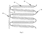
- Fig.2 is a partial plan view of the heat exchanger, which shows an assembled state of the heat exchanger where the flat tube engages with the fin.
- the fin 1 contacts the surface 41 of the flat tube 40 of the heat exchanger via the curved portion 30, thus achieving thermal conduction between the fin and the flat tube.
- the fin exchanges heat with external medium flowing over the fin, and thus achieving the heat exchange between the heat exchanger and the external medium.
- the curved portion of the conventional fin is formed by a single circular arc section which a small radius
- the conventional fin has the following defects: the curved portion and the flat tube make contact only on a small area, resulting in a poor thermal conduction, i.e. resulting in a low fin efficiency; and furthermore, the fin is liable to collapse due to the binding force when assembling the heater exchanger.
- the build-up of water on the fin is mainly caused by the surface tension of the water, and the condensate mainly builds up at the following three areas: the area 7 where the curved portion is located, the area 8 between the fin plates, and the area 9 between the louvers, as shown in Figs.3A and 3B , wherein fig.3A is a plan view of a fin, and fig.3B is a sectional view taken along line B-B in fig.3A .
- the problem of condensate building up at the three areas mentioned above can not be well dealt with by a conventional fin, resulting in the degradation of the performance of the heat exchanger.
- the object of invention is to solve the problems associated with the conventional fin, and to provide a fin for a heat exchanger which can improve the heat exchange performance of the heat exchanger and is not liable to collapse when assembling the heater exchanger.
- Another object of the invention is to provide a fin for a heat exchanger, it can eliminate or improve the build-up of condensate on the fin and thus enhance the heat exchange performance of the heat exchanger.
- Still another object of the invention is to provide a heat exchanger which is provided with a fin in accordance with the invention.
- a fin for a heat exchanger the fin comprises:
- the middle curved section is a circular arc section.
- the middle curved section is an elliptical arc section.
- the side curved sections are circular arc sections.
- the connecting portion is an elliptical arc connecting portion.
- the fin is made of aluminium alloy.
- the central angle of the middle circular arc section is smaller than or equal to 90°.
- the range of the radius R of the middle circular arc section is 0.35mm ⁇ R ⁇ 1 mm.
- the side curved sections are circular arc sections, the range of the radius r of the side circular arc sections is r ⁇ 0.2 mm.
- the fin has at least one of the following features:
- a fin for a heat exchanger the fin comprises:
- the curved connecting portion is a circular arc connecting portion.
- the circular arc connecting portion has at least one of the following features:
- a heat exchanger which comprises a fin as defined in the first and second aspects of the invention.
- the heat exchanger is a parallel flow heat exchanger with the header pipes being installed horizontally.
- the contact area between the flat tubes and the fin increases, the fin efficiency is increased and thus the heat exchange performance of the heat exchanger is enhanced substantially on one hand; and a stable contact is achieved between the fin and the flat tubes and the fin is not liable to collapse after binding on the other hand.
- the optimal design of the fin is carried out by taking into consideration the various parameters which affect the build-up of condensate on the fin surface, the build-up of condensate on the corresponding areas of the fin is eliminated or improved, and thus the heat exchange performance of the heat exchanger is improved further.
- Fig.4 is a partial view and shows a heat exchanger using a fin in accordance with the present invention.
- the fin of the present invention includes a plurality of fin plates 10 which are arranged adjacent to one another and are provided with louvers 20, the fin plates 10 are connected by a curved portion 30.
- the curved portion 30 of the fin according to the present invention is not formed by a single circular arc section with a small radius, instead, the curved portion 30 in accordance with the embodiment shown in the figure is composed of three circular arc sections: a middle circular arc section 31 with a large radius (referred as a large circular arc section hereinafter), two circular arc sections 32 with a radius smaller than the radius of the large circular arc section and located on the sides of the large circular arc section (referred as small circular arc sections hereinafter), the large circular arc section 31 and the small circular arc sections are connected smoothly at their ends.
- a middle circular arc section 31 with a large radius referred as a large circular arc section hereinafter
- two circular arc sections 32 with a radius smaller than the radius of the large circular arc section and located on the sides of the large circular arc section referred as small circular arc sections hereinafter
- the large circular arc section 31 and the small circular arc sections are connected smoothly at their ends.
- the section of the curved portion 30, which contacts the surface 41 of the flat tube 40 is formed by a circular arc section 31 with a large radius, the contact area between the fin and the flat tube surface 41 can be increased substantially, and more stable contact is achieved between the fin and flat tube, so that the fin is not liable to collapse after binding them together.
- the fin efficiency is increased and thus the heat exchange performance of the heat exchanger can be improved substantially on one hand; and on the other hand, the fin is not liable to collapse when assembling the heat exchanger.
- both the middle section of the curved portion 30, which contacts the surface of the flat tube, and the two side sections of the curved portion 30 are circular arc sections.
- the middle section and/or the two side sections on the sides of the middle section are not limited to circular arc sections, other curved sections such as elliptic arc sections are also possible, or the whole curved portion is formed by an elliptic arc section, if only the contact area between the curved portion and the flat tube surface is increased so that the heat exchange performance of the heat exchanger and the binding stability of the fin are improved.
- the two small circular arc sections 32 on the sides of the large circular arc section may have the same radius or have different radiuses, in other words, the curved portion 30 does not necessarily have a symmetric configuration, although it is preferable to have a symmetric configuration in many cases.
- the heat exchanger when used as an evaporator, condensate will build up due to the surface tension of liquid, and the amount of air flowing through the fin of the heat exchanger will decrease and thus the performance of the heat exchanger is degraded.
- the condensate builds up mainly on three areas: the area 7 where the curved portion is located, the area 8 between the fin plates, and the area 9 between the louvers, please refer to figs.3A and 3B .
- the way as to how to effectively deal with the built-up of the condensate on the surface of the fin so as to improve the heat exchange efficiency of the heat exchanger according to the invention will be described below in connection with the various parameters which have effects on the built-up of the condensate on the fin surface.
- fig.5A is a view similar to fig.4 showing the configuration of the fin and the various parameters of the fin;
- Fig5B is a sectional view taken along line B-B in fig5A showing the various parameters of the louvers.
- Fig.6 is a forced diagram of the water on the fin plates, it can be known from the simplified forced diagram that the water can flows downwards when the following relationship is satisfied: tanb > f where f represents the friction coefficient between the water and the surface of the fin plates.
- the angle b of the fin plates, the radius R of the large circular arc section, the pitch P of the fin plates, the central angle c of the large circular arc section and the height H_Fin of the fin approximately satisfy the following relationship in geometry (since the radius r and the central angle d of the small circular arc sections is far smaller than the radius R and the central angle c of the large circular arc section , the effect of the radius r and the central angle d of the small circular arc sections is not considered in the equation ) : tan b ⁇ P 2 - 2 ⁇ R ⁇ sin c 2 H_Fin - 2 ⁇ R ⁇ 1 - cos c 2
- the angle b becomes larger when the central angle c of the large circular arc section becomes smaller, and thus the condensate can flow more easily.
- the central angle c of the large circular arc section becomes smaller, the area of the curved portion becomes smaller, and as a result, the build-up amount of the condensate will decrease even if condensate builds up. Therefore, based on equation (3), if other parameters such as the pitch P of the fin plates remain unchanged, the condensate drainage performance of the fin plates of the fin can be improved by decreasing the central angle c of the large circular arc section.
- the preferable range of the central angle c of the large circular arc section is 0° ⁇ c ⁇ 90°.
- the area where the curved portion is located is a major area at which condensate builds up, the build-up of condensate at the curved portion area is caused by the surface tension of water at the area.
- the surface tension of water is inversely proportional to the radius R of the large circular arc section, the larger the radius of the large circular arc section is, the smaller the surface tension of the water is, and thus condensate is not liable to build up and the built up condensate can be more easily drained.
- the preferable range of the radius R of the large circular arc section is 0.35mm ⁇ R ⁇ 1 mm and the preferable range of the radius r of the small circular arc sections is r ⁇ 0.2 mm under the natural state of the fin before the fin is installed in the heat exchanger.
- the preferable range of the radius R of the large circular arc section is R>0.4mm after the fins have been pressured and installed in the heat exchanger.
- the area between the fin plates is also a major area where condensate builds up, and the build-up of condensate at this area is also caused by the surface tension of the water between the fin plates.
- the pitch of the fin plates is increased, R 1 , R 2 will be increased, and the surface tension of the water between the fin plates will be reduced or eliminated, and thus the build-up of condensate between the fin plates can be decreased or eliminated.
- the preferable range of the pitch P of the fin plates is 2.9mm ⁇ P ⁇ 9 mm.
- the build-up of condensate between the louvers is mainly caused by the surface tension of the water between the adjacent louvers, the formula which describes the surface tension of the water between the louvers is similar to that which describes the surface tension of the water between the fin plates, and accordingly, If the louver gap S of the louvers is increased, R 1 , R 2 will be increased, and the surface tension of the water between the louvers will be reduced or eliminated, and thus the build-up of condensate between the louvers can be decreased or eliminated. Based on calculation and experimental verification, it has been found that the surface tension of water between the louvers can be effectively weakened when the louver gap of the louvers satisfies S ⁇ 0.57mm. And accordingly, the preferable range of the louver gap S of the louver is S ⁇ 0.57mm.
- the preferable range of W_Louver is W_Louver ⁇ 1mm.
- the ratio of the louver height H_Louver of the louvers and the height H_Fin of the fin As described above, the area where the curved portion of the fins is located is a major area where condensate builds up, the build-up of condensate at the area of the curved portion is caused by the surface tension of the water, and if the ratio of the louver height and the height of the fin is increased so that the louvers extends to the area where the curved portion is located, the surface tension of the water at the area of the curved portion will be destroyed, and thus the condensate built up at the curved portion will be decreased.
- the major parameters which have effects on the build-up of condensate on the surface of the fin, include: the angle b of the fin plates, the central angle c of the large circular arc section, the radius R of the large circular arc section and the radius r of the small circular arc sections, the pitch P of the fin plates, the louver gap S of the louvers and the pitch W_Louver of the louvers, the ratio of the louver height H_Louver of the louvers and the height H_Fin of the fin, and etc. Therefore, when carrying out a optimal design of the fin so as to meet the desired design requirements, one can consider only one of the parameters, or consider some or all of the parameters.
- the preferable values of the various parameters which have effects on the build-up of condensate on the fin are not only applicable to a fin in which the section of the curved portion, which contacts the surface of the flat tubes, is formed by a circular arc section with a large curvature radius, they are also applicable to a fin in which the curved portion is formed by a single circular arc section with a relatively small radius, i.e. the fin described in the background part of the description.
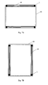
- a parallel flow heat exchanger can be amounted in two manners: one is that the header pipes of the heat exchanger are installed horizontally, the other is that the header pipes of the heat exchanger are installed vertically, as shown in Figs7A and 7B.
- Fig.7A shows the situation where the header pipes are installed vertically
- Fig.7B shows a situation where header pipes are installed horizontally.
- the header pipes are designated by the reference numeral 60
- the flat tubes are designated by the reference numeral 40
- the fins are designated by the reference 1
- the fins are disposed between the adjacent flat tubes.
- a fin the parameters of which have the preferable values mentioned above is preferably used in a heat exchanger with the header tubes installed horizontally, so as to eliminate or improve the build-up of condensate on the hear exchanger as a whole.
- the section of the curved portion of the fin, which contacts the surface of the flat tubes is formed by a circular arc section with a large curvature radius so that the contact area between the flat tubes and the fin increases, the fin efficiency is increased and thus the heat exchange performance of the heat exchanger is substantially enhanced on one hand; and a stable contact is achieved between the fin and the flat tubes, and the fin is not liable to collapse after binding on the other hand.
- the fin is optimally designed by taking into consideration the various parameters which affect the build-up of condensate on the fin surface, the build-up of condensate on the corresponding areas of the fin is eliminated or improved, and thus the heat exchange performance of the heat exchanger is improved.
- the fin of the invention is not limited to a heat exchanger of any particular type, instead, it can be widely used with various heat exchangers which need to use fins.
Landscapes
- Physics & Mathematics (AREA)
- Engineering & Computer Science (AREA)
- Geometry (AREA)
- Thermal Sciences (AREA)
- Mechanical Engineering (AREA)
- General Engineering & Computer Science (AREA)
- Heat-Exchange Devices With Radiators And Conduit Assemblies (AREA)
Abstract
Description
- The present invention relates to a heat exchanger, and more particularly to a fin used with a heat exchanger.
- A heat exchanger is a commonly used component in refrigeration system and air conditioning system, and can be classified as a condenser, an evaporator and so on based on its functions. To improve the heat exchanging performance of a heat exchanger, among others, the heat exchanger is generally provided with a fin.
-
Figs.1A and 1B show a conventional fin used with a parallel flow heat exchanger,Fig. 1A is a plan view of the fin, andFig. 1B is a sectional view taken along line B-B inFig. 1A . - A fin is made of a material with a high thermal conductivity such as aluminium alloy, and is formed by processing an aluminium alloy sheet. As shown in
Fig.1A , thefin 1 of the heat exchanger includes a plurality offin plates 10 adjacent to one another, and each of the fin plates is formed with louvers 20 (as shown inFig.1B in detail), and two adjacent fin plates are connected by acurved portion 30. -
Fig.2 is a partial plan view of the heat exchanger, which shows an assembled state of the heat exchanger where the flat tube engages with the fin. As shown infig.2 , in an assembled state of the heat exchanger, thefin 1 contacts thesurface 41 of theflat tube 40 of the heat exchanger via thecurved portion 30, thus achieving thermal conduction between the fin and the flat tube. And the fin exchanges heat with external medium flowing over the fin, and thus achieving the heat exchange between the heat exchanger and the external medium. - However, since the curved portion of the conventional fin is formed by a single circular arc section which a small radius, the conventional fin has the following defects: the curved portion and the flat tube make contact only on a small area, resulting in a poor thermal conduction, i.e. resulting in a low fin efficiency; and furthermore, the fin is liable to collapse due to the binding force when assembling the heater exchanger.
- Moreover, when the heat exchanger is used as an evaporator, condensate will build up on the surface of the fin due to the surface tension of a liquid, resulting in the decrease of the amount of air flowing through the fin of the heat exchanger, and thus the performance of the heat exchanger is affected. The build-up of water on the fin is mainly caused by the surface tension of the water, and the condensate mainly builds up at the following three areas: the
area 7 where the curved portion is located, thearea 8 between the fin plates, and thearea 9 between the louvers, as shown inFigs.3A and 3B , whereinfig.3A is a plan view of a fin, andfig.3B is a sectional view taken along line B-B infig.3A . The problem of condensate building up at the three areas mentioned above can not be well dealt with by a conventional fin, resulting in the degradation of the performance of the heat exchanger. - In consideration of the problems associated with the conventional fin, there is a need for further improving the heat exchange performance of the fin and thus the heat exchanger.
- The object of invention is to solve the problems associated with the conventional fin, and to provide a fin for a heat exchanger which can improve the heat exchange performance of the heat exchanger and is not liable to collapse when assembling the heater exchanger.
- Another object of the invention is to provide a fin for a heat exchanger, it can eliminate or improve the build-up of condensate on the fin and thus enhance the heat exchange performance of the heat exchanger.
- Still another object of the invention is to provide a heat exchanger which is provided with a fin in accordance with the invention.
- To achieve the above objects, according to a first aspect of the invention, there is provided a fin for a heat exchanger, the fin comprises:
- a plurality of fin plates which are adjacent to one another, each of the fin plates being formed with louvers, and
- a connecting portion which connects adjacent fin plates at an end of the adjacent fin plates;
- wherein the connecting portion comprises a middle curved section and side curved sections located on the sides of the middle curved section, and the curvature radius of the middle curved section is larger than the curvature radius of the side curved sections.
- Preferably, the middle curved section is a circular arc section.
- Preferably, the middle curved section is an elliptical arc section.
- Preferably, the side curved sections are circular arc sections.
- Preferably, the connecting portion is an elliptical arc connecting portion.
- Preferably, the fin is made of aluminium alloy.
- Preferably, the central angle of the middle circular arc section is smaller than or equal to 90°.
- Preferably, the range of the radius R of the middle circular arc section is 0.35mm≦ R≦ 1 mm.
- Preferably, the side curved sections are circular arc sections, the range of the radius r of the side circular arc sections is r≦0.2 mm.
- Preferably, the fin has at least one of the following features:
- a. the angle b of the fin plates satisfies the following formula:

where b is the angle of the fin plates, f is the friction coefficient between water and the surface of the fin plates; - b. the range of the pitch P of the fin plates is 2.8mm ≦ P ≦ 9 mm;
- c. the range of the louver gap S of the louvers is S ≧ 0.57mm;
- d. the range of the pitch W_Louver of the louvers is W_Louver ≧ 1mm;
- e. the range of the ratio of the louver height H_Louver of the louvers and the height H_Fin of the fin is 0.88 ≦ H_Louver/H_Fin ≦ 1.02.
- According to a second aspect of the invention, there is provided a fin for a heat exchanger, the fin comprises:
- a plurality of fin plates which are adjacent to one another, each of the fin plates being formed with louvers, and
- a curved connecting portion which connects adjacent fin plates at an end of the adjacent fin plates;
- wherein the fin has at least one of the following features:
- a. the angle b of the fin plates satisfies the following formula:

where b is the angle of the fin plates, f is the friction coefficient between water and the surface of the fin plates; - b. the range of the pitch P of the fin plates is 2.8mm ≦ P ≦ 9 mm;
- c. the range of the louver gap S of the louvers is S ≧ 0.57mm;
- d. the range of the pitch W_Louver of the louvers is W_Louver ≧ 1mm;
- e. the range of the ratio of the louver height H_Louver of the louvers and the height H_Fin of the fin is 0.88 ≦ H_Louver/H_Fin ≦ 1.02.
- a. the angle b of the fin plates satisfies the following formula:
- Preferably, the curved connecting portion is a circular arc connecting portion.
- Preferably, the circular arc connecting portion has at least one of the following features:
- the value of the central angle of the circular arc connecting portion is smaller than or equal to 90°;
- the range of the radius R of the circular arc connecting portion is 0.35mm ≦ R ≦ 1 mm.
- According to a third aspect of the invention, there is provided a heat exchanger which comprises a fin as defined in the first and second aspects of the invention.
- Preferably, the heat exchanger is a parallel flow heat exchanger with the header pipes being installed horizontally.
- With the technical solution of the invention, since the contact area between the flat tubes and the fin increases, the fin efficiency is increased and thus the heat exchange performance of the heat exchanger is enhanced substantially on one hand; and a stable contact is achieved between the fin and the flat tubes and the fin is not liable to collapse after binding on the other hand. And furthermore, according to the invention, since the optimal design of the fin is carried out by taking into consideration the various parameters which affect the build-up of condensate on the fin surface, the build-up of condensate on the corresponding areas of the fin is eliminated or improved, and thus the heat exchange performance of the heat exchanger is improved further.
- The invention will be described in detail below with reference to the accompanying drawings, in which:
-
Fig. 1A is a plan view showing a conventional fin used with a heat exchanger; -
Fig. 1B is a sectional view taken along line B-B infig.1A ; -
Fig. 2 is a partial plan view of a heat exchanger, showing an assembled state of the heat exchanger where the flat tube of the heat exchanger engages with the fin; -
Fig. 3A and fig.3B are views showing the areas where condensate builds up on the fin, whereinFig.3A is a plan view showing the structure of a fin, andFig.3B is a sectional view taken along line B-B infig.3A ; -
Fig. 4 is a partial view, showing a heat exchanger provided with a fin in accordance with an embodiment of the invention; -
Fig.5A is a view similar tofig.4 , showing the structure of a fin in accordance with the invention; and -
Fig. 5B is a sectional view taken along line B-B infig.5A ; -
Fig.6 is a forced diagram of the condensate on the fin plate of the fin; and -
Fig.7A and 7B are schematic views of a parallel flow heat exchanger, in whichFig. 7A shows a situation where the header pipes are provided vertically, andFig. 7B shows a situation where the header pipes are provided horizontally. - The invention will be described in detail below by taking a parallel flow heat exchanger as an example. It should be noted here that the embodiments of the invention are only illustrative, they are only used to describe the principle of the invention but not to limit the invention. It is obvious to one skilled in the art that the fin according to the invention is not limited to be used with a parallel flow heat exchanger, it can also be used with other heat exchangers which use a fin.
- In the following description, components similar to those in the prior art will be designated with the same reference numerals and their detailed description will be omitted.
- Reference is now made to
Fig.4 which is a partial view and shows a heat exchanger using a fin in accordance with the present invention. - As shown in
Fig.4A , similar to a conventional fin, the fin of the present invention includes a plurality offin plates 10 which are arranged adjacent to one another and are provided withlouvers 20, thefin plates 10 are connected by acurved portion 30. - Unlike the conventional fin, the
curved portion 30 of the fin according to the present invention is not formed by a single circular arc section with a small radius, instead, thecurved portion 30 in accordance with the embodiment shown in the figure is composed of three circular arc sections: a middlecircular arc section 31 with a large radius (referred as a large circular arc section hereinafter), twocircular arc sections 32 with a radius smaller than the radius of the large circular arc section and located on the sides of the large circular arc section (referred as small circular arc sections hereinafter), the largecircular arc section 31 and the small circular arc sections are connected smoothly at their ends. - Since the section of the
curved portion 30, which contacts thesurface 41 of theflat tube 40, is formed by acircular arc section 31 with a large radius, the contact area between the fin and theflat tube surface 41 can be increased substantially, and more stable contact is achieved between the fin and flat tube, so that the fin is not liable to collapse after binding them together. As a result, by increasing the contact area between the flat tube surface and thecurved portion 30 of the fin, the fin efficiency is increased and thus the heat exchange performance of the heat exchanger can be improved substantially on one hand; and on the other hand, the fin is not liable to collapse when assembling the heat exchanger. - In the above description, both the middle section of the
curved portion 30, which contacts the surface of the flat tube, and the two side sections of thecurved portion 30 are circular arc sections. However, it is obvious to one skilled in the art that the middle section and/or the two side sections on the sides of the middle section are not limited to circular arc sections, other curved sections such as elliptic arc sections are also possible, or the whole curved portion is formed by an elliptic arc section, if only the contact area between the curved portion and the flat tube surface is increased so that the heat exchange performance of the heat exchanger and the binding stability of the fin are improved. Furthermore, the two smallcircular arc sections 32 on the sides of the large circular arc section may have the same radius or have different radiuses, in other words, thecurved portion 30 does not necessarily have a symmetric configuration, although it is preferable to have a symmetric configuration in many cases. - As described above, when the heat exchanger is used as an evaporator, condensate will build up due to the surface tension of liquid, and the amount of air flowing through the fin of the heat exchanger will decrease and thus the performance of the heat exchanger is degraded. The condensate builds up mainly on three areas: the
area 7 where the curved portion is located, thearea 8 between the fin plates, and thearea 9 between the louvers, please refer tofigs.3A and 3B . The way as to how to effectively deal with the built-up of the condensate on the surface of the fin so as to improve the heat exchange efficiency of the heat exchanger according to the invention will be described below in connection with the various parameters which have effects on the built-up of the condensate on the fin surface. - Reference is now made to
figs5A and 5B , in whichfig.5A is a view similar tofig.4 showing the configuration of the fin and the various parameters of the fin;Fig5B is a sectional view taken along line B-B infig5A showing the various parameters of the louvers. - The meaning represented by the reference numerals in
Fig.5A and 5B is as follows: - b: angle of the fin plates;
- R: the radius of the large circular arc section;
- r: the radius of the small circular arc section;
- P: the pitch of the fin plates;
- c: the central angle of the large circular arc section;
- d: the central angle of the small circular arc section;
- H_Fin: the height of the fin;
- W_Louver: the pitch of the louvers
- H_Louver: the height of the louvers
- S: the louver gap of the louvers;
- a: the tilt angle of the louvers
- As is well known, the condensate on the fin plates moves downwards from the edge of the fin plates, the larger the angle b is, the more easily the condensate moves.
Fig.6 is a forced diagram of the water on the fin plates, it can be known from the simplified forced diagram that the water can flows downwards when the following relationship is satisfied:
where f represents the friction coefficient between the water and the surface of the fin plates. - Based on theoretical analysis, when the relationship tanb > f is satisfied, the water can flow downwards on the fin plates of the fin, but based on experimental results, the water is easy of moving downwards on the inclined surface of a material such as an aluminium alloy when the force acting in the moving direction of the water is larger than 1.2 times the friction force, i.e. when the formula mg sinb> 1.2 fN is satisfied. As shown in
Fig.6 , by making an analysis of the forces received by the water, we can know N=mgxcos b, and by substituting this for N in the formula mg sinb> 1.2 fN , we can obtain tan b > 1.2f. By taking into consideration such factors as the practical application and the manufacturing feasibility, the preferable range of tan b is
- When the fin is made of an aluminum alloy, the friction coefficient is about 0.15, accordingly we can obtain the following formula:

i.e. arctan0.18 ≦ b ≦ arctan0.585 - As shown in
Fig.5A , the angle b of the fin plates, the radius R of the large circular arc section, the pitch P of the fin plates, the central angle c of the large circular arc section and the height H_Fin of the fin approximately satisfy the following relationship in geometry ( since the radius r and the central angle d of the small circular arc sections is far smaller than the radius R and the central angle c of the large circular arc section , the effect of the radius r and the central angle d of the small circular arc sections is not considered in the equation ) :
- It can be known from equation (3) that, the angle b becomes larger when the central angle c of the large circular arc section becomes smaller, and thus the condensate can flow more easily. And at the same time, when the central angle c of the large circular arc section becomes smaller, the area of the curved portion becomes smaller, and as a result, the build-up amount of the condensate will decrease even if condensate builds up. Therefore, based on equation (3), if other parameters such as the pitch P of the fin plates remain unchanged, the condensate drainage performance of the fin plates of the fin can be improved by decreasing the central angle c of the large circular arc section. By taking into consideration such factors as the practical application and the manufacturing feasibility, the preferable range of the central angle c of the large circular arc section is 0° ≦ c ≦ 90°.
- The area where the curved portion is located is a major area at which condensate builds up, the build-up of condensate at the curved portion area is caused by the surface tension of water at the area. According to the invention, the curved portion is constituted by the large circular arc section and the small circular arc sections located on the sides of the large circular arc section, since the circumferential length of the small circular arc sections is much smaller that the circumferential length of the large circular arc section, the formula which describes the surface tension of the water at the area where the curved portion is located is approximately as follows:

where , Δp-surface tension of water ; σ-surface tension coefficient of water ; R-radius of the large circular arc section. - Since the value of the surface tension coefficient σ of water is basically constant, the surface tension of water is inversely proportional to the radius R of the large circular arc section, the larger the radius of the large circular arc section is, the smaller the surface tension of the water is, and thus condensate is not liable to build up and the built up condensate can be more easily drained. Based on theoretical calculation and actual measurement of the surface tension of the water at the area where the curved portion is located and the windward force received by the water, and taking into consideration such factors as the practical application and the manufacturing feasibility, the preferable range of the radius R of the large circular arc section is 0.35mm ≦ R ≦ 1 mm and the preferable range of the radius r of the small circular arc sections is r ≦ 0.2 mm under the natural state of the fin before the fin is installed in the heat exchanger.
- As is known in the art, after a fin is installed in a heat exchanger, the flat tubes are pressed against the fins by the compression force, the curved portion of the fin deforms under the action of the compression force, such that the radius R of the large circular arc section becomes larger. As a consequence, the contact area between the tube and the fin is further increased, so that the fin is less liable to collapse, and at the same time, the fin efficiency is further improved so as to improve the heat exchange performance. And furthermore, by increasing the value of R, the surface tension of the water at the area of the curved portion is decreased, and thus the condensate can be more easily drained. Therefore, from the point of improving the heat exchange efficiency of the heat exchanger and decreasing the build up of the condensate on the surface of the fin, the preferable range of the radius R of the large circular arc section is R>0.4mm after the fins have been pressured and installed in the heat exchanger.
- The area between the fin plates is also a major area where condensate builds up, and the build-up of condensate at this area is also caused by the surface tension of the water between the fin plates. The formula which describes the surface tension of water between the fin plates is as follows :

where , Δp-surface tension of water ; σ-surface tension coefficient of water ; R 1, R 2 -curvature radiuses of curved surface of water drop at two planes which are perpendicular to each other. - If the pitch of the fin plates is increased, R 1, R 2 will be increased, and the surface tension of the water between the fin plates will be reduced or eliminated, and thus the build-up of condensate between the fin plates can be decreased or eliminated. By taking into consideration such factors as the practical application and the manufacturing feasibility, the preferable range of the pitch P of the fin plates is 2.9mm ≦ P ≦ 9 mm.
- The build-up of condensate between the louvers is mainly caused by the surface tension of the water between the adjacent louvers, the formula which describes the surface tension of the water between the louvers is similar to that which describes the surface tension of the water between the fin plates, and accordingly, If the louver gap S of the louvers is increased, R 1, R 2 will be increased, and the surface tension of the water between the louvers will be reduced or eliminated, and thus the build-up of condensate between the louvers can be decreased or eliminated. Based on calculation and experimental verification, it has been found that the surface tension of water between the louvers can be effectively weakened when the louver gap of the louvers satisfies S ≧ 0.57mm. And accordingly, the preferable range of the louver gap S of the louver is S ≧ 0.57mm.
- It can be known based a geometric analysis that the lover gap S, the louver pitch W_Louver and the tilt angle of the louvers satisfy the following equation :

- By making a comprehensive consideration of the tilt angle a of the louvers, the louver gap S, the actual application and the manufacturing feasibility and so on, the preferable range of W_Louver is W_Louver ≧ 1mm.
- 6, the ratio of the louver height H_Louver of the louvers and the height H_Fin of the fin As described above, the area where the curved portion of the fins is located is a major area where condensate builds up, the build-up of condensate at the area of the curved portion is caused by the surface tension of the water, and if the ratio of the louver height and the height of the fin is increased so that the louvers extends to the area where the curved portion is located, the surface tension of the water at the area of the curved portion will be destroyed, and thus the condensate built up at the curved portion will be decreased. Analysis based on experiments shows that, when the ratio of the louver height H_Louver of the louvers and the height H_Fin of the fin is in the range of 0.88 ≦ H_Louver/H_Fin ≦ 1.02 , the louvers can extends to the area where the curved portion is located and destroy the surface tenstion of the water at the curved portion area. And accordingly, the preferable range of the ratio of the louver height H_Louver and the height H_Fin of the fin is 0.88 ≦ H_Louver/H_Fin ≦ 1.02 , while in the conventional fins, the ratio of the louver height H_Louver and the height H_Fin of the fin is below 0.88.
- As described above, the major parameters, which have effects on the build-up of condensate on the surface of the fin, include: the angle b of the fin plates, the central angle c of the large circular arc section, the radius R of the large circular arc section and the radius r of the small circular arc sections, the pitch P of the fin plates, the louver gap S of the louvers and the pitch W_Louver of the louvers, the ratio of the louver height H_Louver of the louvers and the height H_Fin of the fin, and etc. Therefore, when carrying out a optimal design of the fin so as to meet the desired design requirements, one can consider only one of the parameters, or consider some or all of the parameters.
- What needs to be pointed out is that the preferable values of the various parameters which have effects on the build-up of condensate on the fin are not only applicable to a fin in which the section of the curved portion, which contacts the surface of the flat tubes, is formed by a circular arc section with a large curvature radius, they are also applicable to a fin in which the curved portion is formed by a single circular arc section with a relatively small radius, i.e. the fin described in the background part of the description.
- Furthermore, a parallel flow heat exchanger can be amounted in two manners: one is that the header pipes of the heat exchanger are installed horizontally, the other is that the header pipes of the heat exchanger are installed vertically, as shown in
Figs7A and 7B. Fig.7A shows the situation where the header pipes are installed vertically, andFig.7B shows a situation where header pipes are installed horizontally. In these figures, the header pipes are designated by thereference numeral 60, the flat tubes are designated by thereference numeral 40, and the fins are designated by thereference 1, the fins are disposed between the adjacent flat tubes. When a parallel flow heat exchanger is used as an evaporator, the header tubes are usually installed horizontally, so that the condensate can easily flows downwards from the flat tubes to facilitate the drainage of the condensate. Therefore, a fin the parameters of which have the preferable values mentioned above is preferably used in a heat exchanger with the header tubes installed horizontally, so as to eliminate or improve the build-up of condensate on the hear exchanger as a whole. - It can be seen from above description that, according to one aspect of the invention, since the section of the curved portion of the fin, which contacts the surface of the flat tubes, is formed by a circular arc section with a large curvature radius so that the contact area between the flat tubes and the fin increases, the fin efficiency is increased and thus the heat exchange performance of the heat exchanger is substantially enhanced on one hand; and a stable contact is achieved between the fin and the flat tubes, and the fin is not liable to collapse after binding on the other hand. According to another aspect of the invention, since the fin is optimally designed by taking into consideration the various parameters which affect the build-up of condensate on the fin surface, the build-up of condensate on the corresponding areas of the fin is eliminated or improved, and thus the heat exchange performance of the heat exchanger is improved.
- It is obvious to one skilled in the art that the application the fin of the invention is not limited to a heat exchanger of any particular type, instead, it can be widely used with various heat exchangers which need to use fins.
- The embodiments of the invention have been described above in connection with the drawings. It should be appreciated by one skilled in the art that the above embodiments are only exemplary but not limitative, various modifications are possible without departing from the spirit and scope of the invention.
Claims (15)
- A fin for a heat exchanger, said fin comprising:a plurality of fin plates which are adjacent to one another, each of the fin plates being formed with louvers, anda connecting portion which connects adjacent fin plates at an end of the adjacent fin plates;wherein the connecting portion comprises a middle curved section and side curved sections located on the sides of said middle curved section, and the curvature radius of the middle curved section is larger than the curvature radius of the side curved sections.
- The fin as claimed in claim 1, wherein the middle curved section is a circular arc section.
- The fin as claimed in claim 1, wherein the middle curved section is an elliptical arc section.
- The fin as claimed in claim 2, wherein the side curved sections are circular arc sections.
- The fin as claimed in claim 1, wherein the connecting portion is an elliptical arc connecting portion.
- The fin as claimed in claim 1, wherein said fin is made of aluminium alloy.
- The fin as claimed in claim 2, wherein the central angle of the middle circular arc section is smaller than or equal to 90°.
- The fin as claimed in claim 2, wherein the range of the radius R of the middle circular arc section is 0.35mm ≦ R ≦ 1 mm.
- The fin as claimed in claim 8, wherein said side curved sections are circular arc sections, the range of the radius r of the side circular arc sections is r ≦ 0.2 mm.
- The fin as claimed in any one of claims 1-9, wherein said fin has at least one of the following features:a. the angle b of the fin plates satisfies the following formula:

where b is the angle of the fin plates, f is the friction coefficient between water and the surface of the fin plates;b. the range of the pitch P of the fin plates is 2.9mm ≦ P ≦ 9 mm;c. the range of the louver gap S of the louvers is S ≧ 0.57mm;d. the range of the pitch W_Louver of the louvers is W_Louver ≧ 1mm;e. the range of the ratio of the louver height H_Louver of the louvers and the height H_Fin of the fin is 0.88 ≦ H_Louver/H_Fin ≦ 1.02. - A fin for a heat exchanger, said fin comprising:a plurality of fin plates which are adjacent to one another, each of the fin plates being formed with louvers, anda curved connecting portion which connects adjacent fin plates at an end of the adjacent fin plates;wherein said fin has at least one of the following features:a. the angle b of the fin plates satisfies the following formula:

where b is the angle of the fin plates, f is the friction coefficient between water and the surface of the fin plates;b. the range of the pitch P of the fin plates is 2.8mm ≦ P ≦ 9 mm;c. the range of the louver gap S of the louvers is S ≧ 0.57mm;d. the range of the pitch W_Louver of the louvers is W_Louver ≧ 1mm;e. the range of the ratio of the louver height H_Louver of the louvers and the height H_Fin of the fin is 0.88 ≧ H_Louver/H_Fin ≦ 1.02. - The fin as claimed in claim 11, wherein said curved connecting portion is a circular arc connecting portion.
- The fin as claimed in claim 12, wherein said circular arc connecting portion has at least one of the following features:the value of the central angle of the circular arc connecting portion is smaller than or equal to 90°;the range of the radius R of the circular arc connecting portion is 0.35mm ≦ R ≦ 1 mm.
- A heat exchanger which comprises a fin as claimed in any one of claims 1-13.
- The heat exchanger as claimed in claim 14, wherein said heat exchanger is a parallel flow heat exchanger with the header pipes being installed horizontally.
Applications Claiming Priority (1)
| Application Number | Priority Date | Filing Date | Title |
|---|---|---|---|
| CN2009101196634A CN101846475B (en) | 2009-03-25 | 2009-03-25 | Fin for heat exchanger and heat exchanger with same |
Publications (2)
| Publication Number | Publication Date |
|---|---|
| EP2236971A2 true EP2236971A2 (en) | 2010-10-06 |
| EP2236971A3 EP2236971A3 (en) | 2014-03-05 |
Family
ID=42263624
Family Applications (1)
| Application Number | Title | Priority Date | Filing Date |
|---|---|---|---|
| EP10003127.7A Withdrawn EP2236971A3 (en) | 2009-03-25 | 2010-03-24 | Fin for heat exchanger and heat exchanger using the fin |
Country Status (3)
| Country | Link |
|---|---|
| US (1) | US20100243224A1 (en) |
| EP (1) | EP2236971A3 (en) |
| CN (1) | CN101846475B (en) |
Families Citing this family (13)
| Publication number | Priority date | Publication date | Assignee | Title |
|---|---|---|---|---|
| US20110048688A1 (en) * | 2009-09-02 | 2011-03-03 | Delphi Technologies, Inc. | Heat Exchanger Assembly |
| CN101846465B (en) * | 2010-04-13 | 2011-11-09 | 三花丹佛斯(杭州)微通道换热器有限公司 | Heat exchanger |
| KR101977817B1 (en) * | 2013-02-01 | 2019-05-14 | 한온시스템 주식회사 | Heat exchanger |
| US10113812B2 (en) * | 2013-02-18 | 2018-10-30 | Denso Corporation | Heat exchanger and manufacturing method thereof |
| JP6011481B2 (en) * | 2013-07-12 | 2016-10-19 | 株式会社デンソー | Heat exchanger fins |
| DE102015215053A1 (en) * | 2015-08-06 | 2017-02-09 | Mahle International Gmbh | Heat exchanger |
| CN105547042A (en) * | 2015-12-30 | 2016-05-04 | 郑州大学 | Novel fin heat exchanger of louver |
| CN105526741A (en) * | 2016-02-03 | 2016-04-27 | 合肥长城制冷科技有限公司 | Novel tube-in-sheet evaporator |
| JP2018132247A (en) * | 2017-02-15 | 2018-08-23 | 富士電機株式会社 | vending machine |
| DE102017208324A1 (en) * | 2017-05-17 | 2018-11-22 | Mahle International Gmbh | Heat exchanger |
| EP3473961B1 (en) | 2017-10-20 | 2020-12-02 | Api Heat Transfer, Inc. | Heat exchanger |
| CN110608552A (en) * | 2018-06-15 | 2019-12-24 | 杭州三花微通道换热器有限公司 | heat exchange system |
| CN111380395A (en) * | 2018-12-28 | 2020-07-07 | 丹佛斯有限公司 | Heat exchanger |
Citations (3)
| Publication number | Priority date | Publication date | Assignee | Title |
|---|---|---|---|---|
| JP2001263976A (en) * | 2000-03-15 | 2001-09-26 | Zexel Valeo Climate Control Corp | Heat exchanger |
| US20020195235A1 (en) * | 1999-12-21 | 2002-12-26 | Falta Steven R. | Evaporator with enhanced condensate drainage |
| US20040251004A1 (en) * | 2003-01-02 | 2004-12-16 | Livernois Engineering Company | Serpentine fin with extended louvers for heat exchanger and roll forming tool for manufacturing same |
Family Cites Families (15)
| Publication number | Priority date | Publication date | Assignee | Title |
|---|---|---|---|---|
| JPS56155391A (en) * | 1980-04-30 | 1981-12-01 | Nippon Denso Co Ltd | Corrugated fin type heat exchanger |
| JPH01305296A (en) * | 1988-06-03 | 1989-12-08 | Diesel Kiki Co Ltd | Corrugate fin for heat exchanger |
| JPH02238297A (en) * | 1989-03-08 | 1990-09-20 | Nippondenso Co Ltd | Method of designing heat exchanger and evaluation method |
| JP2949963B2 (en) * | 1991-10-18 | 1999-09-20 | 株式会社デンソー | Corrugated louver fin heat exchanger |
| JP3156008B2 (en) * | 1991-12-06 | 2001-04-16 | 昭和アルミニウム株式会社 | Evaporator manufacturing method |
| JP4207331B2 (en) * | 1999-09-29 | 2009-01-14 | 株式会社デンソー | Double heat exchanger |
| CA2403686C (en) * | 2000-03-23 | 2010-01-26 | Merck & Co., Inc. | Substituted piperidines as melanocortin receptor agonists |
| EP1356248B1 (en) * | 2000-12-28 | 2009-02-11 | Showa Denko K.K. | Layered heat exchangers |
| US6948568B2 (en) * | 2001-04-06 | 2005-09-27 | Deere & Company | Cultivator for aerating a ground surface |
| AU2002360447A1 (en) * | 2001-11-30 | 2003-06-17 | Cooling Technologies, Inc. | Absorption heat-transfer system |
| DE10235038A1 (en) * | 2002-07-31 | 2004-02-12 | Behr Gmbh & Co. | Flat-tube heat exchanger |
| FR2854235B1 (en) * | 2003-04-28 | 2005-08-05 | Valeo Climatisation | OPTIMIZED PROFILE WIND THRUST FOR HEAT EXCHANGER, ESPECIALLY OF MOTOR VEHICLE. |
| DE102004001306A1 (en) * | 2004-01-07 | 2005-08-04 | Behr Gmbh & Co. Kg | Heat exchanger |
| JP2007232246A (en) * | 2006-02-28 | 2007-09-13 | Denso Corp | Heat exchanger |
| US20110048688A1 (en) * | 2009-09-02 | 2011-03-03 | Delphi Technologies, Inc. | Heat Exchanger Assembly |
-
2009
- 2009-03-25 CN CN2009101196634A patent/CN101846475B/en active Active
-
2010
- 2010-03-24 EP EP10003127.7A patent/EP2236971A3/en not_active Withdrawn
- 2010-03-25 US US12/731,769 patent/US20100243224A1/en not_active Abandoned
Patent Citations (3)
| Publication number | Priority date | Publication date | Assignee | Title |
|---|---|---|---|---|
| US20020195235A1 (en) * | 1999-12-21 | 2002-12-26 | Falta Steven R. | Evaporator with enhanced condensate drainage |
| JP2001263976A (en) * | 2000-03-15 | 2001-09-26 | Zexel Valeo Climate Control Corp | Heat exchanger |
| US20040251004A1 (en) * | 2003-01-02 | 2004-12-16 | Livernois Engineering Company | Serpentine fin with extended louvers for heat exchanger and roll forming tool for manufacturing same |
Also Published As
| Publication number | Publication date |
|---|---|
| CN101846475B (en) | 2013-12-11 |
| US20100243224A1 (en) | 2010-09-30 |
| EP2236971A3 (en) | 2014-03-05 |
| CN101846475A (en) | 2010-09-29 |
Similar Documents
| Publication | Publication Date | Title |
|---|---|---|
| US20100243224A1 (en) | Fin for heat exchanger and heat exchanger using the fin | |
| KR101525749B1 (en) | Drainage structure for corrugated-fin heat exchanger | |
| EP2295919B1 (en) | Fin and heat exchanger having the same | |
| CN103238038B (en) | Microchannel Heat Exchanger Fins | |
| CN102047064B (en) | Heat exchanger | |
| US6401809B1 (en) | Continuous combination fin for a heat exchanger | |
| US9534827B2 (en) | Air heat exchanger | |
| US20120227945A1 (en) | Free-draining finned surface architecture for heat exchanger | |
| EP3677865B1 (en) | Flat tube for microchannel heat exchanger, and microchannel heat exchanger | |
| EP2006629A2 (en) | Fin-tube heat exchanger, fin for heat exchanger, and heat pump device | |
| EP2699867B1 (en) | Heat exchanger | |
| US6170566B1 (en) | High performance louvered fin for a heat exchanger | |
| CN218723446U (en) | Fin structure and heat exchanger thereof | |
| US12007178B2 (en) | Heat exchanger | |
| US3217798A (en) | Heat exchanger | |
| US9733024B2 (en) | Tubing element with fins for a heat exchanger | |
| CN101788240B (en) | Fin for heat exchanger and heat exchanger with fin | |
| CN108592654A (en) | Heat exchanger and heat transmission equipment | |
| CN104823012B (en) | Tube element for heat exchanger | |
| CN217716083U (en) | Pipe fin monomer, heat exchanger and air conditioner | |
| JP3775302B2 (en) | Heat exchanger | |
| JP2008116095A (en) | Air heat exchanger | |
| CN109668468B (en) | Fin assembly, micro-channel heat exchanger and air conditioner | |
| JPH10227589A (en) | Waffle type cross fin heat exchanger | |
| KR100248707B1 (en) | Fin-tube type heat exchanger |
Legal Events
| Date | Code | Title | Description |
|---|---|---|---|
| PUAI | Public reference made under article 153(3) epc to a published international application that has entered the european phase |
Free format text: ORIGINAL CODE: 0009012 |
|
| AK | Designated contracting states |
Kind code of ref document: A2 Designated state(s): AT BE BG CH CY CZ DE DK EE ES FI FR GB GR HR HU IE IS IT LI LT LU LV MC MK MT NL NO PL PT RO SE SI SK SM TR |
|
| AX | Request for extension of the european patent |
Extension state: AL BA ME RS |
|
| RAP1 | Party data changed (applicant data changed or rights of an application transferred) |
Owner name: SANHUA HOLDING GROUP CO., LTD. Owner name: DANFOSS A/S |
|
| PUAL | Search report despatched |
Free format text: ORIGINAL CODE: 0009013 |
|
| AK | Designated contracting states |
Kind code of ref document: A3 Designated state(s): AT BE BG CH CY CZ DE DK EE ES FI FR GB GR HR HU IE IS IT LI LT LU LV MC MK MT NL NO PL PT RO SE SI SK SM TR |
|
| AX | Request for extension of the european patent |
Extension state: AL BA ME RS |
|
| RIC1 | Information provided on ipc code assigned before grant |
Ipc: F28F 1/12 20060101AFI20140124BHEP |
|
| 17P | Request for examination filed |
Effective date: 20140827 |
|
| RBV | Designated contracting states (corrected) |
Designated state(s): AT BE BG CH CY CZ DE DK EE ES FI FR GB GR HR HU IE IS IT LI LT LU LV MC MK MT NL NO PL PT RO SE SI SK SM TR |
|
| RAP1 | Party data changed (applicant data changed or rights of an application transferred) |
Owner name: DANFOSS A/S Owner name: SANHUA (HANGZHOU) MICRO CHANNEL HEAT EXCHANGER CO. |
|
| 17Q | First examination report despatched |
Effective date: 20161010 |
|
| STAA | Information on the status of an ep patent application or granted ep patent |
Free format text: STATUS: EXAMINATION IS IN PROGRESS |
|
| STAA | Information on the status of an ep patent application or granted ep patent |
Free format text: STATUS: THE APPLICATION IS DEEMED TO BE WITHDRAWN |
|
| 18D | Application deemed to be withdrawn |
Effective date: 20220505 |