EP2236892A1 - Pipe coupling - Google Patents
Pipe coupling Download PDFInfo
- Publication number
- EP2236892A1 EP2236892A1 EP09004810A EP09004810A EP2236892A1 EP 2236892 A1 EP2236892 A1 EP 2236892A1 EP 09004810 A EP09004810 A EP 09004810A EP 09004810 A EP09004810 A EP 09004810A EP 2236892 A1 EP2236892 A1 EP 2236892A1
- Authority
- EP
- European Patent Office
- Prior art keywords
- graphite
- graphite gasket
- flange
- pipe connection
- connection according
- Prior art date
- Legal status (The legal status is an assumption and is not a legal conclusion. Google has not performed a legal analysis and makes no representation as to the accuracy of the status listed.)
- Granted
Links
Images


Classifications
-
- F—MECHANICAL ENGINEERING; LIGHTING; HEATING; WEAPONS; BLASTING
- F16—ENGINEERING ELEMENTS AND UNITS; GENERAL MEASURES FOR PRODUCING AND MAINTAINING EFFECTIVE FUNCTIONING OF MACHINES OR INSTALLATIONS; THERMAL INSULATION IN GENERAL
- F16L—PIPES; JOINTS OR FITTINGS FOR PIPES; SUPPORTS FOR PIPES, CABLES OR PROTECTIVE TUBING; MEANS FOR THERMAL INSULATION IN GENERAL
- F16L23/00—Flanged joints
- F16L23/04—Flanged joints the flanges being connected by members tensioned in the radial plane
-
- F—MECHANICAL ENGINEERING; LIGHTING; HEATING; WEAPONS; BLASTING
- F01—MACHINES OR ENGINES IN GENERAL; ENGINE PLANTS IN GENERAL; STEAM ENGINES
- F01N—GAS-FLOW SILENCERS OR EXHAUST APPARATUS FOR MACHINES OR ENGINES IN GENERAL; GAS-FLOW SILENCERS OR EXHAUST APPARATUS FOR INTERNAL COMBUSTION ENGINES
- F01N13/00—Exhaust or silencing apparatus characterised by constructional features ; Exhaust or silencing apparatus, or parts thereof, having pertinent characteristics not provided for in, or of interest apart from, groups F01N1/00 - F01N5/00, F01N9/00, F01N11/00
- F01N13/18—Construction facilitating manufacture, assembly, or disassembly
- F01N13/1805—Fixing exhaust manifolds, exhaust pipes or pipe sections to each other, to engine or to vehicle body
- F01N13/1827—Sealings specially adapted for exhaust systems
-
- F—MECHANICAL ENGINEERING; LIGHTING; HEATING; WEAPONS; BLASTING
- F01—MACHINES OR ENGINES IN GENERAL; ENGINE PLANTS IN GENERAL; STEAM ENGINES
- F01N—GAS-FLOW SILENCERS OR EXHAUST APPARATUS FOR MACHINES OR ENGINES IN GENERAL; GAS-FLOW SILENCERS OR EXHAUST APPARATUS FOR INTERNAL COMBUSTION ENGINES
- F01N13/00—Exhaust or silencing apparatus characterised by constructional features ; Exhaust or silencing apparatus, or parts thereof, having pertinent characteristics not provided for in, or of interest apart from, groups F01N1/00 - F01N5/00, F01N9/00, F01N11/00
- F01N13/18—Construction facilitating manufacture, assembly, or disassembly
- F01N13/1838—Construction facilitating manufacture, assembly, or disassembly characterised by the type of connection between parts of exhaust or silencing apparatus, e.g. between housing and tubes, between tubes and baffles
- F01N13/1844—Mechanical joints
- F01N13/1855—Mechanical joints the connection being realised by using bolts, screws, rivets or the like
Definitions
- the invention relates to a pipe connection, comprising a first pipe and a second pipe, which are fluidly connected to each other, wherein the first pipe has a first flange and the second pipe has a second flange, wherein the first flange and the second flange an installation space for a graphite gasket form, wherein the graphite gasket is received under compression in the installation space and wherein a fastening means connecting the first flange with the second flange element.
- the closing force of the fastening means is at least partially reduced by the deformations of the graphite gasket.
- the tubing may loosen within the tubing connection so that the entire tubing connection is no longer tight.
- the invention is therefore the object of a pipe joint of the type mentioned in such a way and further, that it shows a simple high mounting even at temporarily loaded pipes permanently high tightness.
- the present invention solves the above-mentioned object by a pipe joint having the features of patent claim 1.
- the pipe connection is characterized in that a limiting means is provided which limits the compression of the graphite gasket.
- a limiting means ensures a minimum volume of the installation space.
- the graphite gasket can not be crimped or deformed beyond a predefined extent if loads are acting on the pipelines.
- a limiting means causes a force bypass and thus a limitation of the load on the graphite gasket.
- the graphite gasket is used in the Assembly once defined compressed and assumes a desired geometry. This geometry changes in permanent use of the pipe connection, even with loaded pipelines essentially no longer. In that regard, leaks or gaps are inventively avoided and realized a permanent tightness. Consequently, the object mentioned above is achieved.
- the limiting means could support the flange members against the graphite gasket. This ensures that the load on the graphite gasket remains virtually unchanged when the pipes are loaded and the graphite gasket is not deformed beyond a predetermined level.
- the limiting means could be formed on the flange elements. This specific embodiment causes a low-part construction of the pipe connection.
- the limiting means could rest against a joint of the flange elements.
- the flange elements are thus directly adjacent to each other and support each other relative to the graphite gasket.
- a clamping force introduced by the fastening means does not cause any further deformation of the graphite gasket after contact of the flange elements with each other, but serves to externally fix the flange elements to one another.
- Both the first flange element and the second flange element could have a funnel-shaped radially outwardly curved collar, wherein at least one of the collars protrudes parallel to the pipeline axes oriented edge as a limiting means.
- the funnel-shaped configuration of the flange causes a compression of the graphite gasket such that it assumes a trapezoidal shape in cross section and tapers in the radial direction.
- the parallel to at least one pipe axis oriented edge overlaps the graphite gasket of outside and prevents their radial emigration.
- the edge comes to rest at a joint of the flange elements and thereby acts as a limiting means. The edge ensures that the volume of the installation space is not reduced above a predefined level. against this background, it is also conceivable that an edge is formed on each of the flange elements. The length of the edge therefore allows adjustment of the minimum volume of the installation space.
- the fastening means could be formed as a U-shaped or V-shaped clamp. Such a fastening means can grip around and pull together two flange elements, namely by reducing the diameter of the clamp.
- the graphite gasket could be formed as a graphite gasket and made of a braided packing of graphite foil.
- a wicker wrap of graphite foil is extremely soft and can be easily pressed into a desired shape.
- its braided structure is closed during the pressing of the graphite seal, so that the graphite seal acts like a solid pressed ring. With very little application of force, the braided packing can cling to uneven or scratched sealing surfaces and reliably seal them.
- a braided packing allows a compensation of large manufacturing tolerances and errors of the flange elements.
- the flange can be made against this background of relatively thin sheet or thin-walled tube. The flange elements could be pulled, pressed, rolled, pressed or welded.
- the graphite gasket could be braided diagonally three times. This graphite gasket is characterized by good cross-sectional stability and dense braiding structure.
- the graphite gasket could be doubly diagonal braided. This graphite gasket is characterized by a good elasticity.
- the graphite gasket could have a joint at which two free ends of the graphite gasket are pressed together sealingly.
- the graphite gasket can be pushed up or down almost like a piston ring onto a pipeline.
- the joint allows expansion of the graphite seal when the pipe widens in its outer diameter.
- a braided packing made of graphite foil it is particularly advantageously possible to re-seal the two free ends without their joint being visually recognizable.
- the softness of the braided wrap allows this surprising healing effect at the junction of the graphite gasket.
- the free ends are chamfered to form a large contact surface for each other.
- the pipes could have an outside diameter of 100 to 400 mm.
- pipes can be coupled reliably tightly to one another.
- the flange tend after compression, welding or pressing on a pipe to a ripple that can not be compensated with the known sealing concepts.
- a weld on a flange member provides a bead which must be ground or counterbalanced to effect a reliable seal.
- the braided packing can be deformed surprisingly strong and surprisingly even coarser unevenness of the pipes or flange elements.
- the pipeline connection can be used in particular in exhaust pipes of motor vehicles.
- the urea technology is in The emission reduction standard has been further developed since October 1, 2006, when the Euro 4 standard applies to exhaust gases - and the more stringent Euro 5 standard will apply as of October 1, 2009. By 2012, it is expected that the European urea requirement for commercial vehicles will already be around 3.5 million tonnes.
- Urea water solutions are environmentally friendly emission control chemicals that have been used in commercial vehicles (especially trucks and buses). Urea water solutions are also used to reduce nitrogen oxides in stationary engines and to purify flue gas in power plants.
- urea-water solutions For the use of urea-water solutions, an additional tank is attached to motor vehicles.
- the consumption of urea-water solution is about 4-6% of normal fuel consumption and is equivalent to about 1.4 liters for a heavy truck over a distance of 100 km.
- AdBlue A known urea-water solution is AdBlue.
- AdBlue (DIN 70070 / AUS32) is the brand name for a water-clear, synthetically produced 32.5% solution of ultrapure urea in demineralized water, which is used to treat exhaust gases in an SCR catalyst.
- SCR selective catalytic reduction
- NOx nitrogen oxides
- the SCR process uses ammonia, which is obtained on board the vehicle from urea.
- the lying in a separate tank urea-water solution is z.
- nitrogen oxides are converted into nitrogen and water vapor.
- the ratio of urea solution to diesel fuel is about 1:20 to 1:30
- the pipe connection described here is suitable for use in a plant which uses urea for the purification of exhaust gases.
- a graphite gasket made of a braided packing of graphite foil is also suitable for use in a plant which uses urea for the purification of exhaust gases. Such a graphite seal is space-saving.
- Fig. 1 shows a pipeline connection, comprising a first pipe 1 and a second pipe 2, which are fluidly connected to each other, wherein the first pipe 1, a first flange 3 and the second pipe 2, a second flange 4, wherein the first flange 3 and the second flange 4 form an installation space 5 for a graphite gasket 6, the graphite gasket 6 being received under compression in the installation space 5, and a fastening means 7 connecting the first flange element 3 to the second flange element 4.
- the pipe connection has a limiting means 8, which limits the compression of the graphite gasket 6.
- the limiting means 8 ensures a minimum volume of the installation space 5.
- the graphite gasket 6 can not be compressed or deformed beyond a predefined extent if loads act on the pipes 1, 2.
- the limiting means 8 causes a force bypass and thus a relief of the graphite gasket 6.
- the graphite gasket 6 is pressed once defined during assembly and assumes a desired geometry. This geometry changes in permanent use of the pipe connection, even with loaded pipelines 1, 2 essentially no longer. In that regard, leaks or gaps are avoided and realized a permanent tightness.
- the limiting means 8 supports the flange elements 3, 4 with respect to the graphite gasket 6.
- the limiting means 8 is formed on the second flange 4. This specific embodiment causes a low-part construction of the pipe connection.
- the limiting means 8 abuts against a joint 9 of the flange elements 3, 4.
- the flange elements 3, 4 lie directly against each other and support each other relative to the graphite seal 6.
- a introduced by the fastening means 7 clamping force causes after conditioning of the flange 3, 4 to each other no further deformation of the graphite gasket 6, but serves the outer fixation of the flange 3, 4 to each other.
- Both the first flange element 3 and the second flange element 4 each have a funnel-shaped radially outwardly curved collar 10, 11, wherein the collar 11 of the second flange 4 projects parallel to the pipe axis oriented edge 12 as a limiting means 8.
- the funnel-shaped configuration of the flange elements 3, 4 causes the graphite gasket 6 to be pressed in such a way that it takes on a shape which has a shape in cross-section and tapers in the radial direction.
- the parallel to at least one pipe axis oriented edge 12 engages over the graphite gasket 6 from the outside and prevents their radial emigration. Furthermore, the edge 12 abuts against the joint 9 of the flange elements 3, 4 and thus acts as a limiting means 8.
- the edge 12 ensures that the volume of the installation space 5 is not reduced beyond a predefined level.
- the fastening means 7 is formed as a U-shaped clamp.
- the fastening means 7 surrounds the two flange elements 3, 4 and pulls them together, namely, by the diameter of the clamp is reduced.
- the graphite gasket 6 is formed as a graphite gasket and made of a braided packing of graphite foil.
- a wicker wrap of graphite foil is extremely soft and can be easily pressed into a desired shape.
- its braided structure is closed during pressing of the graphite seal 6, so that the graphite seal 6 acts like a solid pressed ring. With very little application of force, the braided packing can cling to uneven or scratched sealing surfaces and reliably seal them.
- a braided packing allows a compensation of manufacturing tolerances and errors of the flange elements 3, 4.
- the flange 3, 4 are each welded to the pipes 1, 2 and consist of thin sheet metal.
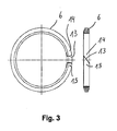
- Fig. 3 shows two views of graphite gaskets 6. Left in Fig. 3 is a plan view of her ring shape, right in Fig. 3 a sectional view is shown, showing its trapezoidal shape.
- the graphite seals 6 each have a joint 13, on which two free ends 14, 15 of the graphite seals 6 are pressed together sealingly.
- a graphite seal 6 as a piston ring almost powerless on a pipe 1, 2 or a flange 3, 4 or be deported.
- the joint 13 of the graphite seals 6 allows a widening of the graphite seal when the pipe 1, 2 widens in its outer diameter.
- By using a braided packing of graphite foil it is particularly advantageously possible to re-seal the two free ends 14, 15 without the joint 13 of a graphite seal 6 being visually recognizable.
- the softness of Flechtpackung allows this surprising healing effect at the joint 13 of a graphite seal 6.
- the free ends 14, 15 are right in Fig. 3 Preferably formed bevelled to form a large mutual contact surface for each other, but may also be straight, as shown in left Fig. 3 is shown.
- the graphite seals 6 described here are suitable for operation at temperatures of up to 500 ° C and almost resistant to all media except oxygen. Surprisingly, the graphite seals 6 are made of a braided packing of graphite foil according to Fig. 3 for use in a plant which uses urea to purify exhaust gases.
- the pipe connection described here shows at an outer diameter of the pipes 1, 2 of 120 mm at an internal pressure of 1 bar, a leakage of 0.1 liter / minute.
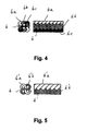
- Fig. 4 shows by way of example a triple diagonal braided graphite gasket 6, which is made of a braided packing of graphite foil.
- the graphite foil comprises a plurality of intertwined braiding yarns, wherein, by way of example, the wicker yarns 6a, 6b, 6c are characterized.
- the wicker wrap made of graphite foil is extremely soft and can be easily pressed into a desired shape.
- a braided packing whose braid structure, namely the interstices between the Flechtgamen 6a, 6b, 6c, when pressing the graphite seal 6 is closed, so that the graphite seal acts like a solid pressed ring.
- This graphite gasket 6 is characterized by good cross-sectional stability and dense braiding structure.
- Fig. 4 shows two views of the graphite gasket 6. Left in Fig. 4 is a sectional view of the graphite gasket 6 and shown on the right is a plan view of the graphite gasket 6.
- Fig. 5 shows by way of example a double-diagonal braided graphite gasket 6 ', which is made of a braided packing of graphite foil.
- the graphite foil comprises a plurality of intertwined plaiting yarns, the plaiting yarns 6'a, 6'b being characterized by way of example.
- the wicker wrap made of graphite foil is extremely soft and can be easily pressed into a desired shape.
- a braided packing In a braided packing, its braided structure, namely, the interstices between the braiding yarns 6'a, 6'b, is closed during pressing of the graphite gasket 6 ', so that the graphite gasket acts like a solid pressed ring.
- This graphite gasket 6 ' is characterized by a good elasticity.
- Fig. 5 shows two views of the graphite gasket 6 '. Left in Fig. 5 is a sectional view of the graphite gasket 6 'and shown on the right a plan view of the graphite gasket 6'.
Abstract
Description
Die Erfindung betrifft eine Rohrleitungsverbindung, umfassend eine erste Rohrleitung und eine zweite Rohrleitung, welche fluidführend miteinander verbunden sind, wobei die erste Rohrleitung ein erstes Flanschelement und die zweite Rohrleitung ein zweites Flanschelement aufweist, wobei das erste Flanschelement und das zweite Flanschelement einen Einbauraum für eine Graphitdichtung ausbilden, wobei die Graphitdichtung unter Verpressung im Einbauraum aufgenommen ist und wobei ein Befestigungsmittel das erste Flanschelement mit dem zweiten Flanschelement verbindet.The invention relates to a pipe connection, comprising a first pipe and a second pipe, which are fluidly connected to each other, wherein the first pipe has a first flange and the second pipe has a second flange, wherein the first flange and the second flange an installation space for a graphite gasket form, wherein the graphite gasket is received under compression in the installation space and wherein a fastening means connecting the first flange with the second flange element.
Aus der
Des Weiteren wird durch die Deformierungen der Graphitdichtung die Schließkraft des Befestigungsmittels zumindest bereichsweise reduziert. Die Rohrleitungen können sich innerhalb der Rohrleitungsverbindung lockern, so dass die gesamte Rohrleitungsverbindung nicht mehr dicht ist.Furthermore, the closing force of the fastening means is at least partially reduced by the deformations of the graphite gasket. The tubing may loosen within the tubing connection so that the entire tubing connection is no longer tight.
Der Erfindung liegt daher die Aufgabe zugrunde, eine Rohrleitungsverbindung der eingangs genannten Art derart auszugestalten und weiterzubilden, dass sie nach einfacher Montage auch bei zeitweise belasteten Rohrleitungen eine dauerhaft hohe Dichtheit zeigt.The invention is therefore the object of a pipe joint of the type mentioned in such a way and further, that it shows a simple high mounting even at temporarily loaded pipes permanently high tightness.
Die vorliegende Erfindung löst die zuvor genannte Aufgabe durch eine Rohrleitungsverbindung mit den Merkmalen des Patentanspruchs 1.The present invention solves the above-mentioned object by a pipe joint having the features of patent claim 1.
Danach ist die Rohrleitungsverbindung dadurch gekennzeichnet, dass ein Begrenzungsmittel vorgesehen ist, welches die Verpressung der Graphitdichtung begrenzt.Thereafter, the pipe connection is characterized in that a limiting means is provided which limits the compression of the graphite gasket.
Erfindungsgemäß ist erkannt worden, dass ein Begrenzungsmittel ein Mindestvolumen des Einbauraums sicherstellt. Die Graphitdichtung kann nicht über ein vordefiniertes Maß hinaus verpresst oder deformiert werden, wenn auf die Rohrleitungen Lasten einwirken. Des Weiteren ist erkannt worden, dass ein Begrenzungsmittel einen Kraftnebenschluss und damit eine Begrenzung der Belastung der Graphitdichtung bewirkt. Die Graphitdichtung wird bei der Montage einmalig definiert verpresst und nimmt eine gewünschte Geometrie an. Diese Geometrie ändert sich im dauerhaften Gebrauch der Rohrleitungsverbindung auch bei belasteten Rohrleitungen im Wesentlichen nicht mehr. Insoweit werden Leckagen oder Spalte erfindungsgemäß vermieden und eine dauerhafte Dichtheit realisiert. Folglich ist die eingangs genannte Aufgabe gelöst.According to the invention, it has been recognized that a limiting means ensures a minimum volume of the installation space. The graphite gasket can not be crimped or deformed beyond a predefined extent if loads are acting on the pipelines. Furthermore, it has been recognized that a limiting means causes a force bypass and thus a limitation of the load on the graphite gasket. The graphite gasket is used in the Assembly once defined compressed and assumes a desired geometry. This geometry changes in permanent use of the pipe connection, even with loaded pipelines essentially no longer. In that regard, leaks or gaps are inventively avoided and realized a permanent tightness. Consequently, the object mentioned above is achieved.
Das Begrenzungsmittel könnte die Flanschelemente gegenüber der Graphitdichtung abstützen. Hierdurch ist sicher gestellt, dass die Belastung der Graphitdichtung bei Belastung der Rohrleitungen nahezu unverändert bleibt und die Graphitdichtung nicht über ein vorgegebenes Maß deformiert wird.The limiting means could support the flange members against the graphite gasket. This ensures that the load on the graphite gasket remains virtually unchanged when the pipes are loaded and the graphite gasket is not deformed beyond a predetermined level.
Das Begrenzungsmittel könnte an den Flanschelementen angeformt sein. Diese konkrete Ausgestaltung bewirkt einen teilearmen Aufbau der Rohrleitungsverbindung.The limiting means could be formed on the flange elements. This specific embodiment causes a low-part construction of the pipe connection.
Das Begrenzungsmittel könnte an einer Stoßstelle der Flanschelemente anliegen. Die Flanschelemente liegen dadurch direkt aneinander und stützen sich gegenseitig relativ zur Graphitdichtung ab. Eine durch das Befestigungsmittel eingeleitete Spannkraft bewirkt nach Anlage der Flanschelemente aneinander keine weitere Deformation der Graphitdichtung, sondern dient der äußeren Fixierung der Flanschelemente aneinander.The limiting means could rest against a joint of the flange elements. The flange elements are thus directly adjacent to each other and support each other relative to the graphite gasket. A clamping force introduced by the fastening means does not cause any further deformation of the graphite gasket after contact of the flange elements with each other, but serves to externally fix the flange elements to one another.
Sowohl das erste Flanschelement als auch das zweite Flanschelement könnten einen trichterförmig radial nach außen gewölbten Kragen aufweist, wobei von mindestens einem der Kragen ein zu den Rohrleitungsachsen parallel orientierter Rand als Begrenzungsmittel abragt. Die trichterförmige Ausgestaltung der Flanschelemente bewirkt ein Verpressen der Graphitdichtung derart, dass sie eine im Querschnitt trapezförmige Form einnimmt und sich in radialer Richtung verjüngt. Der parallel zu mindestens einer Rohrleitungsachse orientierte Rand übergreift die Graphitdichtung von außen und verhindert deren radiales Auswandern. Des Weiteren kommt der Rand an einer Stoßstelle der Flanschelemente zur Anlage und wirkt dadurch als Begrenzungsmittel. Der Rand stellt sicher, dass das Volumen des Einbauraums nicht über ein vordefiniertes Maß reduziert wird. Vor diesem Hintergrund ist auch denkbar, dass an jedem der Flanschelemente ein Rand ausgebildet ist. Die Länge des Randes erlaubt daher eine Einstellung des Mindestvolumens des Einbauraums.Both the first flange element and the second flange element could have a funnel-shaped radially outwardly curved collar, wherein at least one of the collars protrudes parallel to the pipeline axes oriented edge as a limiting means. The funnel-shaped configuration of the flange causes a compression of the graphite gasket such that it assumes a trapezoidal shape in cross section and tapers in the radial direction. The parallel to at least one pipe axis oriented edge overlaps the graphite gasket of outside and prevents their radial emigration. Furthermore, the edge comes to rest at a joint of the flange elements and thereby acts as a limiting means. The edge ensures that the volume of the installation space is not reduced above a predefined level. Against this background, it is also conceivable that an edge is formed on each of the flange elements. The length of the edge therefore allows adjustment of the minimum volume of the installation space.
Das Befestigungsmittel könnte als U-förmige oder V-förmige Klemmschelle ausgebildet sein. Ein solches Befestigungsmittel kann zwei Flanschelemente umgreifen und aneinanderziehen, indem nämlich der Durchmesser der Klemmschelle vermindert wird.The fastening means could be formed as a U-shaped or V-shaped clamp. Such a fastening means can grip around and pull together two flange elements, namely by reducing the diameter of the clamp.
Die Graphitdichtung könnte als Graphitdichtring ausgebildet und aus einer Flechtpackung aus Graphitfolie gefertigt sein. Eine Flechtpackung aus Graphitfolie ist äußerst weich und kann sehr leicht in eine gewünschte Form verpresst werden. Bei einer Flechtpackung wird deren Flechtstruktur beim Verpressen der Graphitdichtung geschlossen, so dass die Graphitdichtung wie ein massiver gepresster Ring wirkt. Bei sehr geringer Kraftbeaufschlagung kann die Flechtpackung sich an unebene oder zerkratzte Dichtflächen anschmiegen und diese zuverlässig abdichten. Eine Flechtpackung erlaubt eine Kompensierung von großen Fertigungstoleranzen und Fehlern der Flanschelemente. Die Flanschelemente können vor diesem Hintergrund aus relativ dünnem Blech oder dünnwandigem Rohr gefertigt sein. Die Flanschelemente könnten gezogen, gedrückt, gerollt, gepresst oder geschweisst sein.The graphite gasket could be formed as a graphite gasket and made of a braided packing of graphite foil. A wicker wrap of graphite foil is extremely soft and can be easily pressed into a desired shape. In a braided packing, its braided structure is closed during the pressing of the graphite seal, so that the graphite seal acts like a solid pressed ring. With very little application of force, the braided packing can cling to uneven or scratched sealing surfaces and reliably seal them. A braided packing allows a compensation of large manufacturing tolerances and errors of the flange elements. The flange can be made against this background of relatively thin sheet or thin-walled tube. The flange elements could be pulled, pressed, rolled, pressed or welded.
Die Graphitdichtung könnte dreifach diagonal geflochten sein. Diese Graphitdichtung zeichnet sich durch eine gute Querschnittsstabilität und dichte Flechtstruktur aus.The graphite gasket could be braided diagonally three times. This graphite gasket is characterized by good cross-sectional stability and dense braiding structure.
Die Graphitdichtung könnte zweifach diagonal geflochten sein. Diese Graphitdichtung zeichnet sich durch eine gute Elastizität aus.The graphite gasket could be doubly diagonal braided. This graphite gasket is characterized by a good elasticity.
Die Graphitdichtung könnte eine Stoßstelle aufweisen, an welcher zwei freie Enden der Graphitdichtung miteinander dichtend verpresst sind. Durch diese konkrete Ausgestaltung kann die Graphitdichtung wie ein Kolbenring nahezu kraftlos auf eine Rohrleitung auf- oder abgeschoben werden. Die Stoßstelle erlaubt eine Aufweitung des Graphitdichtrings, wenn die Rohrleitung sich in ihrem Außendurchmesser aufweitet. Durch die Verwendung einer Flechtpackung aus Graphitfolie ist es besonders vorteilhaft möglich, die zwei freien Enden wieder dichtend aneinander anzulegen, ohne dass deren Stoßstelle optisch erkennbar ist. Die Weichheit der Flechtpackung erlaubt diesen überraschenden Heilungseffekt an der Stoßstelle der Graphitdichtung. Vorzugsweise sind die freien Enden abgeschrägt ausgebildet, um eine große Anlagefläche füreinander auszubilden.The graphite gasket could have a joint at which two free ends of the graphite gasket are pressed together sealingly. As a result of this specific configuration, the graphite gasket can be pushed up or down almost like a piston ring onto a pipeline. The joint allows expansion of the graphite seal when the pipe widens in its outer diameter. By using a braided packing made of graphite foil, it is particularly advantageously possible to re-seal the two free ends without their joint being visually recognizable. The softness of the braided wrap allows this surprising healing effect at the junction of the graphite gasket. Preferably, the free ends are chamfered to form a large contact surface for each other.
Die Rohrleitungen könnten einen Außendurchmesser von 100 bis 400 mm aufweisen. Überraschend können mit der hier beschriebenen Rohrleitungsverbindung, welche als Graphitdichtung eine weiche Flechtpackung aus Graphitfolie aufweist, Rohrleitungen zuverlässig dicht aneinander gekoppelt werden. Die Flanschelemente neigen nach Stauchung, Aufschweissen oder Aufdrücken auf eine Rohrleitung zu einer Welligkeit, die mit den bekannten Dichtkonzepten nicht ausgeglichen werden kann. Insbesondere bietet eine Schweißnaht auf einem Flanschelement eine Wulst aus, die abgeschliffen oder ausgeglichen werden muss, um eine zuverlässige Dichtheit zu bewirken. Die Flechtpackung kann überraschend stark nachverformt werden und gleicht überraschend auch gröbere Unebenheiten der Rohrleitungen bzw. Flanschelemente aus.The pipes could have an outside diameter of 100 to 400 mm. Surprisingly, with the pipe connection described here, which has a soft braided packing of graphite foil as the graphite seal, pipes can be coupled reliably tightly to one another. The flange tend after compression, welding or pressing on a pipe to a ripple that can not be compensated with the known sealing concepts. In particular, a weld on a flange member provides a bead which must be ground or counterbalanced to effect a reliable seal. The braided packing can be deformed surprisingly strong and surprisingly even coarser unevenness of the pipes or flange elements.
Die Rohrleitungsverbindung kann insbesondere in Abgasleitungen von Kraftfahrzeugen Verwendung finden. Derzeit wird die Harnstofftechnik im Rahmen der Abgasreinhaltung weiterentwickelt, da seit 1. Oktober 2006 die Euro-4-Norm für Abgase gilt - und bereits zum 1. Oktober 2009 die strengere Euro-5-Norm gelten wird. Bis zum Jahr 2012 ist damit zu rechnen, dass der europäische Harnstoffbedarf für Nutzfahrzeuge bereits bei etwa 3,5 Millionen Tonnen liegen wird.The pipeline connection can be used in particular in exhaust pipes of motor vehicles. At present, the urea technology is in The emission reduction standard has been further developed since October 1, 2006, when the Euro 4 standard applies to exhaust gases - and the more stringent Euro 5 standard will apply as of October 1, 2009. By 2012, it is expected that the European urea requirement for commercial vehicles will already be around 3.5 million tonnes.
Harnstoff-Wasser-Lösungen sind umweltschonende Chemikalien zur Abgasreinigung, welche bislang in Nutzfahrzeugen (insbesondere bei LKW und Omnibussen) verwendet werden. Harnstoff-Wasser-Lösungen werden zur Reduzierung von Stickoxiden auch in stationären Motoren und zur Rauchgasreinigung in Kraftwerken genutzt.Urea water solutions are environmentally friendly emission control chemicals that have been used in commercial vehicles (especially trucks and buses). Urea water solutions are also used to reduce nitrogen oxides in stationary engines and to purify flue gas in power plants.
Für die Verwendung von Harnstoff-Wasser-Lösungen ist an Kraftfahrzeugen ein zusätzlicher Tank angebracht. Der Verbrauch von Harnstoff-Wasser-Lösung beträgt etwa 4-6 % des normalen Kraftstoffverbrauchs und entspricht bei schweren LKW etwa 1,4 Liter auf einer Strecke von 100 km.For the use of urea-water solutions, an additional tank is attached to motor vehicles. The consumption of urea-water solution is about 4-6% of normal fuel consumption and is equivalent to about 1.4 liters for a heavy truck over a distance of 100 km.
Eine bekannte Harnstoff-Wasser-Lösung ist AdBlue. AdBlue (DIN 70070/AUS32) ist der Markenname für eine wasserklare, synthetisch hergestellte 32,5 %-ige Lösung von hochreinem Harnstoff in demineralisiertem Wasser, die zur Nachbehandlung von Abgasen in einem SCR-Katalysator benutzt wird. Dabei wird durch selektive katalytische Reduktion (englisch selective catalytic reduction, SCR) der Ausstoß von Stickoxiden (NOx) um etwa 90 % (im Stationärbetrieb) reduziert. Der Einsatz von AdBlue im PKW-Bereich ist zur Zeit in der Testphase.A known urea-water solution is AdBlue. AdBlue (DIN 70070 / AUS32) is the brand name for a water-clear, synthetically produced 32.5% solution of ultrapure urea in demineralized water, which is used to treat exhaust gases in an SCR catalyst. In this case, by selective catalytic reduction (English selective catalytic reduction, SCR) reduces the emission of nitrogen oxides (NOx) by approximately 90% (in the steady operation). The use of AdBlue in the car sector is currently in the test phase.
Das SCR-Verfahren nutzt Ammoniak, welches an Bord des Fahrzeugs aus Hamstoff gewonnen wird. Die in einem separaten Tank liegende Harnstoff-Wasser-Lösung wird z. B. mittels Dosierpumpe oder Injektor dosiert in den Abgasstrom eingespritzt und sorgt im SCR-Katalysator für eine chemische Reaktion. Hierbei werden nur die Stickoxide in Stickstoff und Wasserdampf umgewandelt. Das Verhältnis von Harnstofflösung zu Dieselkraftstoff beträgt etwa 1:20 bis 1:30The SCR process uses ammonia, which is obtained on board the vehicle from urea. The lying in a separate tank urea-water solution is z. B. metered by metering pump or injector injected into the exhaust stream and provides in the SCR catalyst for a chemical Reaction. Here, only the nitrogen oxides are converted into nitrogen and water vapor. The ratio of urea solution to diesel fuel is about 1:20 to 1:30
Überraschend eignet sich die hier beschriebene Rohrleitungsverbindung zur Verwendung in einer Anlage, welche Harnstoff zur Reinigung von Abgasen verwendet. Überraschend eignet sich auch eine Graphitdichtung aus einer Flechtpackung aus Graphitfolie zur Verwendung in einer Anlage, welche Harnstoff zur Reinigung von Abgasen verwendet. Eine solche Graphitdichtung ist platzsparend.Surprisingly, the pipe connection described here is suitable for use in a plant which uses urea for the purification of exhaust gases. Surprisingly, a graphite gasket made of a braided packing of graphite foil is also suitable for use in a plant which uses urea for the purification of exhaust gases. Such a graphite seal is space-saving.
Beim Einsprühen einer Harnstoff-Wasser-Lösung in die Abgasleitungen eines Kraftfahrzeugs entsteht ein Aerosol, das mit dem NOx im Abgas reagiert. Ein geringer Teil der Harnstoff-Wasser-Lösung verdampft jedoch nicht und kann aus Einsprühdüsen in die Flanschelementverbindungen des Stands der Technik tropfen. Dort kristallisiert der Harnstoff und bildet harte Beläge und Ablagerungen an den Leitungswänden sowie in allen Taschen und Spalten, in welche die Lösung eindringen kann. Die Harnstoff-Wasser-Lösung dringt durch Osmose auch in poröse Dichtungen ein oder rinnt in Fugen von Blechdichtungen. Die Kristallisation des Harnstoffs führt zu einer Verhärtung und Versprödung der betroffenen Bereiche, so dass keine Rückfederungseigenschaften mehr ausgebildet werden können. Bei für Abgasleitungen typischen wechselnden thermischen Belastungen bilden sich immer neue Spalte und Ritzen aus, in die Harnstoff eindringen kann. Schließlich kann der Harnstoff sogar nach außen treten und von Rohrleitungsverbindungen des Stands der Technik in Form von Stalaktiten oder Zapfen abragen.When spraying a urea-water solution in the exhaust pipes of a motor vehicle, an aerosol is formed, which reacts with the NOx in the exhaust gas. However, a small portion of the urea-water solution does not evaporate and may drip from injection nozzles into the flange element joints of the prior art. There, the urea crystallizes and forms hard deposits and deposits on the duct walls as well as in all pockets and crevices into which the solution can penetrate. The urea-water solution also penetrates into porous seals by osmosis or runs in joints of sheet metal seals. The crystallization of the urea leads to a hardening and embrittlement of the affected areas, so that no springback properties can be formed more. With alternating thermal loads typical for exhaust pipes, new gaps and cracks are constantly emerging, into which urea can penetrate. Finally, the urea may even leak out and protrude from prior art tubing connections in the form of stalactites or spigots.
Es hat sich gezeigt, dass Graphitdichtringe aus Flechtpackungen aus Graphitfolie dauerhaft elastisch bleiben und Harnstoff überraschend nicht in die deren Flechtstruktur eindringt, obwohl man dies erwarten würde. Schließlich besteht die Flechtstruktur aus einzelnen Segmenten, die aneinandergepresst sind. Infolge der guten Anschmiegfähigkeit der Graphitdichtringe an die teilweise unebenen Flanschelemente, werden sogar Ritzen und Spalten vermieden, in denen Harnstoff kristallisieren kann. der zuvor beschriebene Effekt hat sich insbesondere bei Verwendung von AdBlue positiv gezeigt.It has been shown that graphite sealing rings made of graphite foil braided packing remain permanently elastic and urea surprisingly does not remain in the whose weave structure penetrates, although one would expect this. Finally, the braiding structure consists of individual segments which are pressed against each other. As a result of the good conformability of the graphite sealing rings to the partially uneven flange elements, even cracks and gaps are avoided in which urea can crystallize. the effect described above has been shown to be positive, in particular when using AdBlue.
Es gibt nun verschiedene Möglichkeiten, die Lehre der vorliegenden Erfindung in vorteilhafter Weise auszugestalten und weiterzubilden. Dazu ist einerseits auf die nachgeordneten Ansprüche, andererseits auf die nachfolgende Erläuterung eines bevorzugten Ausführungsbeispiels der erfindungsgemäßen Lehre anhand der Zeichnung zu verweisen.There are now various possibilities for designing and developing the teaching of the present invention in an advantageous manner. For this purpose, on the one hand to the subordinate claims, on the other hand, to refer to the following explanation of a preferred embodiment of the teaching of the invention with reference to the drawings.
In Verbindung mit der Erläuterung des bevorzugten Ausführungsbeispiels anhand der Zeichnung werden auch im Allgemeinen bevorzugte Ausgestaltungen und Weiterbildungen der Lehre erläutert.In conjunction with the explanation of the preferred embodiment with reference to the drawing, generally preferred embodiments and developments of the teaching are explained.
In der Zeichung zeigen
- Fig. 1
- eine Schnittzeichnung einer Rohrleitungsverbindung mit einer U- bzw. V-förmigen Klemmschelle,
- Fig. 2
- eine Detailansicht des Einbauraums für die Graphitdichtung,
- Fig. 3
- zwei Ansichten des Graphitdichtrings, der aus einer Flechtpackung aus einer Graphitfolie gefertigt ist,
- Fig. 4
- zwei Ansichten einer dreifach diagonal geflochtenen Graphitdichtung und
- Fig. 5
- zwei Ansichten einer zweifach diagonal geflochtenen Graphitdichtung.
- Fig. 1
- a sectional drawing of a pipe connection with a U- or V-shaped clamp,
- Fig. 2
- a detailed view of the installation space for the graphite gasket,
- Fig. 3
- two views of the graphite sealing ring, which is made of a braided packing of a graphite foil,
- Fig. 4
- two views of a triple diagonal braided graphite gasket and
- Fig. 5
- two views of a double diagonal braided graphite gasket.
In
Das Begrenzungsmittel 8 liegt an an einer Stoßstelle 9 der Flanschelemente 3, 4 an. Die Flanschelemente 3, 4 liegen dadurch direkt aneinander und stützen sich gegenseitig relativ zur Graphitdichtung 6 ab. Eine durch das Befestigungsmittel 7 eingeleitete Spannkraft bewirkt nach Anlage der Flanschelemente 3, 4 aneinander keine weitere Deformation der Graphitdichtung 6, sondern dient der äußeren Fixierung der Flanschelemente 3, 4 aneinander.The limiting means 8 abuts against a joint 9 of the
Sowohl das erste Flanschelement 3 als auch das zweite Flanschelement 4 weisen jeweils einen trichterförmig radial nach außen gewölbten Kragen 10, 11 auf, wobei vom Kragen 11 des zweiten Flanschelements 4 ein zu den Rohrleitungsachsen parallel orientierter Rand 12 als Begrenzungsmittel 8 abragt. Die trichterförmige Ausgestaltung der Flanschelemente 3, 4 bewirkt ein Verpressen der Graphitdichtung 6 derart, dass sie eine im Querschnitt rapezförmige Form einnimmt und sich in radialer Richtung verjüngt. Der parallel zu mindestens einer Rohrleitungsachse orientierte Rand 12 übergreift die Graphitdichtung 6 von außen und verhindert deren radiales Auswandern. Des Weiteren kommt der Rand 12 an der Stoßstelle 9 der Flanschelemente 3, 4 zur Anlage und wirkt dadurch als Begrenzungsmittel 8. Der Rand 12 stellt sicher, dass das Volumen des Einbauraums 5 nicht über ein vordefiniertes Maß reduziert wird.Both the
Das Befestigungsmittel 7 ist als U-förmige Klemmschelle ausgebildet. Das Befestigungsmittel 7 umgreift die zwei Flanschelemente 3, 4 und zieht diese aneinander, indem nämlich der Durchmesser der Klemmschelle vermindert wird.The fastening means 7 is formed as a U-shaped clamp. The fastening means 7 surrounds the two
Die Graphitdichtung 6 ist als Graphitdichtring ausgebildet und aus einer Flechtpackung aus Graphitfolie gefertigt. Eine Flechtpackung aus Graphitfolie ist äußerst weich und kann sehr leicht in eine gewünschte Form verpresst werden. Bei einer Flechtpackung wird deren Flechtstruktur beim Verpressen der Graphitdichtung 6 geschlossen, so dass die Graphitdichtung 6 wie ein massiver gepresster Ring wirkt. Bei sehr geringer Kraftbeaufschlagung kann die Flechtpackung sich an unebene oder zerkratzte Dichtflächen anschmiegen und diese zuverlässig abdichten. Eine Flechtpackung erlaubt eine Kompensierung von Fertigungstoleranzen und Fehlern der Flanschelemente 3, 4. Die Flanschelemente 3, 4 sind jeweils auf die Rohrleitungen 1, 2 aufgeschweisst und bestehen aus dünnem Blech.The
Die Graphitdichtungen 6 weisen je eine Stoßstelle 13 auf, an welcher zwei freie Enden 14, 15 der Graphitdichtungen 6 miteinander dichtend verpresst sind. Durch diese konkrete Ausgestaltung kann eine Graphitdichtung 6 wie ein Kolbenring nahezu kraftlos auf eine Rohrleitung 1, 2 oder ein Flanschelement 3, 4 auf- oder abgeschoben werden. Die Stoßstelle 13 der Graphitdichtungen 6 erlaubt eine Aufweitung des Graphitdichtrings, wenn die Rohrleitung 1, 2 sich in ihrem Außendurchmesser aufweitet. Durch die Verwendung einer Flechtpackung aus Graphitfolie ist es besonders vorteilhaft möglich, die zwei freien Enden 14, 15 wieder dichtend aneinander anzulegen, ohne dass die Stoßstelle 13 einer Graphitdichtung 6 optisch erkennbar ist. Die Weichheit der Flechtpackung erlaubt diesen überraschenden Heilungseffekt an der Stoßstelle 13 einer Graphitdichtung 6. Die freien Enden 14, 15 sind rechts in
Die hier beschriebenen Graphitdichtungen 6 sind bei Temperaturen von bis zu 500° C betriebstauglich und nahezu gegen alle Medien außer Sauerstoff beständig. Überraschend eignen sich die Graphitdichtungen 6 aus einer Flechtpackung aus Graphitfolie gemäß
Die hier beschriebene Rohrleitungsverbindung zeigt bei einem Außendurchmesser der Rohrleitungen 1, 2 von 120 mm bei einem Innendruck von 1 bar eine Leckage von 0,1 Liter/ Minute.The pipe connection described here shows at an outer diameter of the
Hinsichtlich weiterer vorteilhafter Ausgestaltungen und Weiterbildungen der erfindungsgemäßen Lehre wird einerseits auf den allgemeinen Teil der Beschreibung und andererseits auf die beigefügten Ansprüche verwiesen.With regard to further advantageous embodiments and developments of the teaching of the invention reference is made on the one hand to the general part of the description and on the other hand to the appended claims.
Abschließend sei ganz besonders hervorgehoben, dass das zuvor gewählte Ausführungsbeispiel lediglich zur Erörterung der erfindungsgemäßen Lehre dient, diese jedoch nicht auf dieses Ausführungsbeispiel einschränkt.Finally, it should be particularly emphasized that the previously selected embodiment is only for the purpose of discussion of the teaching of the invention, but this does not limit this embodiment.
Claims (12)
dadurch gekennzeichnet, dass ein Begrenzungsmittel (8) vorgesehen ist, welches die Verpressung der Graphitdichtung (6, 6') begrenzt.Pipe connection, comprising a first pipe (1) and a second pipe (2), which are fluidly connected to each other, wherein the first pipe (1) has a first flange member (3) and the second pipe (2) has a second flange member (4) in which the first flange element (3) and the second flange element (4) form an installation space (5) for a graphite gasket (6, 6 '), the graphite gasket (6, 6') being received under compression in the installation space (5) and wherein a fastening means (7) connects the first flange element (3) to the second flange element (4),
characterized in that a limiting means (8) is provided, which limits the compression of the graphite gasket (6, 6 ').
Priority Applications (1)
| Application Number | Priority Date | Filing Date | Title |
|---|---|---|---|
| EP20090004810 EP2236892B1 (en) | 2009-04-01 | 2009-04-01 | Pipe coupling |
Applications Claiming Priority (1)
| Application Number | Priority Date | Filing Date | Title |
|---|---|---|---|
| EP20090004810 EP2236892B1 (en) | 2009-04-01 | 2009-04-01 | Pipe coupling |
Publications (2)
| Publication Number | Publication Date |
|---|---|
| EP2236892A1 true EP2236892A1 (en) | 2010-10-06 |
| EP2236892B1 EP2236892B1 (en) | 2013-06-19 |
Family
ID=41059587
Family Applications (1)
| Application Number | Title | Priority Date | Filing Date |
|---|---|---|---|
| EP20090004810 Active EP2236892B1 (en) | 2009-04-01 | 2009-04-01 | Pipe coupling |
Country Status (1)
| Country | Link |
|---|---|
| EP (1) | EP2236892B1 (en) |
Citations (7)
| Publication number | Priority date | Publication date | Assignee | Title |
|---|---|---|---|---|
| GB1267540A (en) * | 1969-07-15 | 1972-03-22 | Gamah Corp | Coupling assemblies for connecting fluid conduits |
| DE2425121A1 (en) * | 1973-05-23 | 1974-12-12 | Citroen Sa | CONNECTING DEVICE FOR LINES |
| DE3725744C1 (en) * | 1987-08-04 | 1988-12-22 | Goetze Ag, 5093 Burscheid, De | Seal ring with outer surface as sliding face - consists of metal wire or metal fibre material pressed together and powdered to fine grain material |
| US5947533A (en) * | 1996-08-02 | 1999-09-07 | Fisher; Ronald K. | Gasket assembly with elastomer expansion area |
| DE20317425U1 (en) | 2003-11-12 | 2004-01-15 | Burgmann Automotive Gmbh | System for connecting sections of IC engine exhaust comprises flanges on ends of sections which have complementary slope and clamp fitted over them, one flange having peripheral groove in which sealing ring is mounted |
| WO2005043025A1 (en) | 2003-10-30 | 2005-05-12 | Daimlerchrysler Ag | Pipe joint |
| US20060123775A1 (en) * | 2004-12-14 | 2006-06-15 | Borgwarner Inc. | Turbocharger-catalytic converter assembly |
-
2009
- 2009-04-01 EP EP20090004810 patent/EP2236892B1/en active Active
Patent Citations (7)
| Publication number | Priority date | Publication date | Assignee | Title |
|---|---|---|---|---|
| GB1267540A (en) * | 1969-07-15 | 1972-03-22 | Gamah Corp | Coupling assemblies for connecting fluid conduits |
| DE2425121A1 (en) * | 1973-05-23 | 1974-12-12 | Citroen Sa | CONNECTING DEVICE FOR LINES |
| DE3725744C1 (en) * | 1987-08-04 | 1988-12-22 | Goetze Ag, 5093 Burscheid, De | Seal ring with outer surface as sliding face - consists of metal wire or metal fibre material pressed together and powdered to fine grain material |
| US5947533A (en) * | 1996-08-02 | 1999-09-07 | Fisher; Ronald K. | Gasket assembly with elastomer expansion area |
| WO2005043025A1 (en) | 2003-10-30 | 2005-05-12 | Daimlerchrysler Ag | Pipe joint |
| DE20317425U1 (en) | 2003-11-12 | 2004-01-15 | Burgmann Automotive Gmbh | System for connecting sections of IC engine exhaust comprises flanges on ends of sections which have complementary slope and clamp fitted over them, one flange having peripheral groove in which sealing ring is mounted |
| US20060123775A1 (en) * | 2004-12-14 | 2006-06-15 | Borgwarner Inc. | Turbocharger-catalytic converter assembly |
Also Published As
| Publication number | Publication date |
|---|---|
| EP2236892B1 (en) | 2013-06-19 |
Similar Documents
| Publication | Publication Date | Title |
|---|---|---|
| DE102009025054A1 (en) | turbine housing | |
| EP3372736B1 (en) | Connection unit | |
| DE202008010025U1 (en) | Metallic seal, in particular exhaust manifold gasket | |
| EP2807350B1 (en) | Seal for an exhaust aftertreatment device in an internal combustion engine | |
| WO2011036245A1 (en) | Extendible coiled tube | |
| DE19937444C1 (en) | Fuel distribution device for i.c. engine fuel injection system has fuel injection valves fitted directly to fuel distribution line via connection elements fitted to fuel distribution openings along fuel distribution line | |
| EP2320116B1 (en) | Pipe conduit connection | |
| EP1774217A1 (en) | Connection for high-pressure media conduits | |
| EP3093545A1 (en) | Pipe connection device for connecting two pipe ends, especially two pipe ends in an exhaust line of a combustion engine | |
| DE102011118862B4 (en) | Modular flange | |
| EP2236892B1 (en) | Pipe coupling | |
| DE19949867C1 (en) | Sealing ring for a corrugated pipe | |
| DE102010037772A1 (en) | Winding hose for insulating exhaust gas pipe element for exhaust system of e.g. passenger car, has different preprofiled metal bands including band windings circularly connected by solder material in parts around specific degrees | |
| EP1950482B1 (en) | Line assembly with a seal in the overlap area | |
| WO2005100774A1 (en) | Fuel-supplying high-pressure pipe for internal combustion engines | |
| EP1985388B1 (en) | High pressure-resistant metal bellow and method for manufacturing the same | |
| EP1783413A2 (en) | Arrangement for connecting the ends of a metal pipe with helical corrugations with a connecting piece | |
| EP3397850A1 (en) | Component of a hydraulic device, in particular a fuel injection system for internal combustion engines | |
| DE102010061544A1 (en) | Winding tube for exhaust pipes of motor vehicles, has two profiled strips with contact area made of different materials, where material of strips has certain relative sliding friction coefficient | |
| EP2577011B1 (en) | Valve arrangement for metering a fluid medium in an exhaust line of an internal combustion engine | |
| WO2012010264A1 (en) | Bellows-type compensator | |
| EP2851533B1 (en) | Flexible pipe element | |
| WO2019038182A1 (en) | Heat shield having a sealing element | |
| EP3828397B1 (en) | Connecting unit | |
| DE3934755C2 (en) | Metallic hollow profile sealing ring, in particular for motor vehicle engines |
Legal Events
| Date | Code | Title | Description |
|---|---|---|---|
| PUAI | Public reference made under article 153(3) epc to a published international application that has entered the european phase |
Free format text: ORIGINAL CODE: 0009012 |
|
| AK | Designated contracting states |
Kind code of ref document: A1 Designated state(s): AT BE BG CH CY CZ DE DK EE ES FI FR GB GR HR HU IE IS IT LI LT LU LV MC MK MT NL NO PL PT RO SE SI SK TR |
|
| AX | Request for extension of the european patent |
Extension state: AL BA RS |
|
| 17P | Request for examination filed |
Effective date: 20110606 |
|
| RAP1 | Party data changed (applicant data changed or rights of an application transferred) |
Owner name: ELRINGKLINGER AG |
|
| 17Q | First examination report despatched |
Effective date: 20110915 |
|
| GRAP | Despatch of communication of intention to grant a patent |
Free format text: ORIGINAL CODE: EPIDOSNIGR1 |
|
| RIC1 | Information provided on ipc code assigned before grant |
Ipc: F01N 13/18 20100101ALI20121206BHEP Ipc: F16L 23/04 20060101AFI20121206BHEP |
|
| GRAS | Grant fee paid |
Free format text: ORIGINAL CODE: EPIDOSNIGR3 |
|
| GRAA | (expected) grant |
Free format text: ORIGINAL CODE: 0009210 |
|
| AK | Designated contracting states |
Kind code of ref document: B1 Designated state(s): AT BE BG CH CY CZ DE DK EE ES FI FR GB GR HR HU IE IS IT LI LT LU LV MC MK MT NL NO PL PT RO SE SI SK TR |
|
| REG | Reference to a national code |
Ref country code: GB Ref legal event code: FG4D Free format text: NOT ENGLISH |
|
| REG | Reference to a national code |
Ref country code: CH Ref legal event code: EP |
|
| REG | Reference to a national code |
Ref country code: AT Ref legal event code: REF Ref document number: 617860 Country of ref document: AT Kind code of ref document: T Effective date: 20130715 |
|
| REG | Reference to a national code |
Ref country code: IE Ref legal event code: FG4D Free format text: LANGUAGE OF EP DOCUMENT: GERMAN |
|
| REG | Reference to a national code |
Ref country code: DE Ref legal event code: R096 Ref document number: 502009007344 Country of ref document: DE Effective date: 20130814 |
|
| PG25 | Lapsed in a contracting state [announced via postgrant information from national office to epo] |
Ref country code: SI Free format text: LAPSE BECAUSE OF FAILURE TO SUBMIT A TRANSLATION OF THE DESCRIPTION OR TO PAY THE FEE WITHIN THE PRESCRIBED TIME-LIMIT Effective date: 20130619 Ref country code: NO Free format text: LAPSE BECAUSE OF FAILURE TO SUBMIT A TRANSLATION OF THE DESCRIPTION OR TO PAY THE FEE WITHIN THE PRESCRIBED TIME-LIMIT Effective date: 20130919 Ref country code: ES Free format text: LAPSE BECAUSE OF FAILURE TO SUBMIT A TRANSLATION OF THE DESCRIPTION OR TO PAY THE FEE WITHIN THE PRESCRIBED TIME-LIMIT Effective date: 20130930 Ref country code: FI Free format text: LAPSE BECAUSE OF FAILURE TO SUBMIT A TRANSLATION OF THE DESCRIPTION OR TO PAY THE FEE WITHIN THE PRESCRIBED TIME-LIMIT Effective date: 20130619 Ref country code: SE Free format text: LAPSE BECAUSE OF FAILURE TO SUBMIT A TRANSLATION OF THE DESCRIPTION OR TO PAY THE FEE WITHIN THE PRESCRIBED TIME-LIMIT Effective date: 20130619 Ref country code: GR Free format text: LAPSE BECAUSE OF FAILURE TO SUBMIT A TRANSLATION OF THE DESCRIPTION OR TO PAY THE FEE WITHIN THE PRESCRIBED TIME-LIMIT Effective date: 20130920 Ref country code: LT Free format text: LAPSE BECAUSE OF FAILURE TO SUBMIT A TRANSLATION OF THE DESCRIPTION OR TO PAY THE FEE WITHIN THE PRESCRIBED TIME-LIMIT Effective date: 20130619 |
|
| REG | Reference to a national code |
Ref country code: LT Ref legal event code: MG4D |
|
| PG25 | Lapsed in a contracting state [announced via postgrant information from national office to epo] |
Ref country code: BG Free format text: LAPSE BECAUSE OF FAILURE TO SUBMIT A TRANSLATION OF THE DESCRIPTION OR TO PAY THE FEE WITHIN THE PRESCRIBED TIME-LIMIT Effective date: 20130919 Ref country code: HR Free format text: LAPSE BECAUSE OF FAILURE TO SUBMIT A TRANSLATION OF THE DESCRIPTION OR TO PAY THE FEE WITHIN THE PRESCRIBED TIME-LIMIT Effective date: 20130619 |
|
| REG | Reference to a national code |
Ref country code: NL Ref legal event code: VDEP Effective date: 20130619 |
|
| PG25 | Lapsed in a contracting state [announced via postgrant information from national office to epo] |
Ref country code: LV Free format text: LAPSE BECAUSE OF FAILURE TO SUBMIT A TRANSLATION OF THE DESCRIPTION OR TO PAY THE FEE WITHIN THE PRESCRIBED TIME-LIMIT Effective date: 20130619 |
|
| PG25 | Lapsed in a contracting state [announced via postgrant information from national office to epo] |
Ref country code: SK Free format text: LAPSE BECAUSE OF FAILURE TO SUBMIT A TRANSLATION OF THE DESCRIPTION OR TO PAY THE FEE WITHIN THE PRESCRIBED TIME-LIMIT Effective date: 20130619 Ref country code: IS Free format text: LAPSE BECAUSE OF FAILURE TO SUBMIT A TRANSLATION OF THE DESCRIPTION OR TO PAY THE FEE WITHIN THE PRESCRIBED TIME-LIMIT Effective date: 20131019 Ref country code: PT Free format text: LAPSE BECAUSE OF FAILURE TO SUBMIT A TRANSLATION OF THE DESCRIPTION OR TO PAY THE FEE WITHIN THE PRESCRIBED TIME-LIMIT Effective date: 20131021 Ref country code: EE Free format text: LAPSE BECAUSE OF FAILURE TO SUBMIT A TRANSLATION OF THE DESCRIPTION OR TO PAY THE FEE WITHIN THE PRESCRIBED TIME-LIMIT Effective date: 20130619 Ref country code: CZ Free format text: LAPSE BECAUSE OF FAILURE TO SUBMIT A TRANSLATION OF THE DESCRIPTION OR TO PAY THE FEE WITHIN THE PRESCRIBED TIME-LIMIT Effective date: 20130619 Ref country code: CY Free format text: LAPSE BECAUSE OF FAILURE TO SUBMIT A TRANSLATION OF THE DESCRIPTION OR TO PAY THE FEE WITHIN THE PRESCRIBED TIME-LIMIT Effective date: 20130911 |
|
| PG25 | Lapsed in a contracting state [announced via postgrant information from national office to epo] |
Ref country code: NL Free format text: LAPSE BECAUSE OF FAILURE TO SUBMIT A TRANSLATION OF THE DESCRIPTION OR TO PAY THE FEE WITHIN THE PRESCRIBED TIME-LIMIT Effective date: 20130619 Ref country code: RO Free format text: LAPSE BECAUSE OF FAILURE TO SUBMIT A TRANSLATION OF THE DESCRIPTION OR TO PAY THE FEE WITHIN THE PRESCRIBED TIME-LIMIT Effective date: 20130619 Ref country code: PL Free format text: LAPSE BECAUSE OF FAILURE TO SUBMIT A TRANSLATION OF THE DESCRIPTION OR TO PAY THE FEE WITHIN THE PRESCRIBED TIME-LIMIT Effective date: 20130619 |
|
| PG25 | Lapsed in a contracting state [announced via postgrant information from national office to epo] |
Ref country code: CY Free format text: LAPSE BECAUSE OF FAILURE TO SUBMIT A TRANSLATION OF THE DESCRIPTION OR TO PAY THE FEE WITHIN THE PRESCRIBED TIME-LIMIT Effective date: 20130619 |
|
| PLBE | No opposition filed within time limit |
Free format text: ORIGINAL CODE: 0009261 |
|
| STAA | Information on the status of an ep patent application or granted ep patent |
Free format text: STATUS: NO OPPOSITION FILED WITHIN TIME LIMIT |
|
| PG25 | Lapsed in a contracting state [announced via postgrant information from national office to epo] |
Ref country code: DK Free format text: LAPSE BECAUSE OF FAILURE TO SUBMIT A TRANSLATION OF THE DESCRIPTION OR TO PAY THE FEE WITHIN THE PRESCRIBED TIME-LIMIT Effective date: 20130619 |
|
| 26N | No opposition filed |
Effective date: 20140320 |
|
| PG25 | Lapsed in a contracting state [announced via postgrant information from national office to epo] |
Ref country code: IT Free format text: LAPSE BECAUSE OF FAILURE TO SUBMIT A TRANSLATION OF THE DESCRIPTION OR TO PAY THE FEE WITHIN THE PRESCRIBED TIME-LIMIT Effective date: 20130619 |
|
| REG | Reference to a national code |
Ref country code: DE Ref legal event code: R097 Ref document number: 502009007344 Country of ref document: DE Effective date: 20140320 |
|
| PG25 | Lapsed in a contracting state [announced via postgrant information from national office to epo] |
Ref country code: LU Free format text: LAPSE BECAUSE OF FAILURE TO SUBMIT A TRANSLATION OF THE DESCRIPTION OR TO PAY THE FEE WITHIN THE PRESCRIBED TIME-LIMIT Effective date: 20140401 Ref country code: MC Free format text: LAPSE BECAUSE OF FAILURE TO SUBMIT A TRANSLATION OF THE DESCRIPTION OR TO PAY THE FEE WITHIN THE PRESCRIBED TIME-LIMIT Effective date: 20130619 |
|
| REG | Reference to a national code |
Ref country code: CH Ref legal event code: PL |
|
| REG | Reference to a national code |
Ref country code: IE Ref legal event code: MM4A |
|
| PG25 | Lapsed in a contracting state [announced via postgrant information from national office to epo] |
Ref country code: CH Free format text: LAPSE BECAUSE OF NON-PAYMENT OF DUE FEES Effective date: 20140430 Ref country code: LI Free format text: LAPSE BECAUSE OF NON-PAYMENT OF DUE FEES Effective date: 20140430 |
|
| PG25 | Lapsed in a contracting state [announced via postgrant information from national office to epo] |
Ref country code: IE Free format text: LAPSE BECAUSE OF NON-PAYMENT OF DUE FEES Effective date: 20140401 |
|
| REG | Reference to a national code |
Ref country code: AT Ref legal event code: MM01 Ref document number: 617860 Country of ref document: AT Kind code of ref document: T Effective date: 20140401 |
|
| REG | Reference to a national code |
Ref country code: DE Ref legal event code: R082 Ref document number: 502009007344 Country of ref document: DE Representative=s name: HOEGER, STELLRECHT & PARTNER PATENTANWAELTE MB, DE |
|
| PG25 | Lapsed in a contracting state [announced via postgrant information from national office to epo] |
Ref country code: AT Free format text: LAPSE BECAUSE OF NON-PAYMENT OF DUE FEES Effective date: 20140401 |
|
| PG25 | Lapsed in a contracting state [announced via postgrant information from national office to epo] |
Ref country code: MT Free format text: LAPSE BECAUSE OF FAILURE TO SUBMIT A TRANSLATION OF THE DESCRIPTION OR TO PAY THE FEE WITHIN THE PRESCRIBED TIME-LIMIT Effective date: 20130619 |
|
| REG | Reference to a national code |
Ref country code: FR Ref legal event code: PLFP Year of fee payment: 8 |
|
| PG25 | Lapsed in a contracting state [announced via postgrant information from national office to epo] |
Ref country code: TR Free format text: LAPSE BECAUSE OF FAILURE TO SUBMIT A TRANSLATION OF THE DESCRIPTION OR TO PAY THE FEE WITHIN THE PRESCRIBED TIME-LIMIT Effective date: 20130619 Ref country code: BE Free format text: LAPSE BECAUSE OF FAILURE TO SUBMIT A TRANSLATION OF THE DESCRIPTION OR TO PAY THE FEE WITHIN THE PRESCRIBED TIME-LIMIT Effective date: 20140430 Ref country code: HU Free format text: LAPSE BECAUSE OF FAILURE TO SUBMIT A TRANSLATION OF THE DESCRIPTION OR TO PAY THE FEE WITHIN THE PRESCRIBED TIME-LIMIT; INVALID AB INITIO Effective date: 20090401 |
|
| REG | Reference to a national code |
Ref country code: FR Ref legal event code: PLFP Year of fee payment: 9 |
|
| REG | Reference to a national code |
Ref country code: FR Ref legal event code: PLFP Year of fee payment: 10 |
|
| PG25 | Lapsed in a contracting state [announced via postgrant information from national office to epo] |
Ref country code: MK Free format text: LAPSE BECAUSE OF FAILURE TO SUBMIT A TRANSLATION OF THE DESCRIPTION OR TO PAY THE FEE WITHIN THE PRESCRIBED TIME-LIMIT Effective date: 20130619 |
|
| REG | Reference to a national code |
Ref country code: DE Ref legal event code: R082 Ref document number: 502009007344 Country of ref document: DE Representative=s name: HOEGER, STELLRECHT & PARTNER PATENTANWAELTE MB, DE |
|
| P01 | Opt-out of the competence of the unified patent court (upc) registered |
Effective date: 20230512 |
|
| PGFP | Annual fee paid to national office [announced via postgrant information from national office to epo] |
Ref country code: FR Payment date: 20230417 Year of fee payment: 15 Ref country code: DE Payment date: 20230418 Year of fee payment: 15 |
|
| PGFP | Annual fee paid to national office [announced via postgrant information from national office to epo] |
Ref country code: GB Payment date: 20230420 Year of fee payment: 15 |