EP2236833A1 - Screw compressor - Google Patents
Screw compressor Download PDFInfo
- Publication number
- EP2236833A1 EP2236833A1 EP08867336A EP08867336A EP2236833A1 EP 2236833 A1 EP2236833 A1 EP 2236833A1 EP 08867336 A EP08867336 A EP 08867336A EP 08867336 A EP08867336 A EP 08867336A EP 2236833 A1 EP2236833 A1 EP 2236833A1
- Authority
- EP
- European Patent Office
- Prior art keywords
- rotor
- seal portion
- screw
- gate rotor
- shaft
- Prior art date
- Legal status (The legal status is an assumption and is not a legal conclusion. Google has not performed a legal analysis and makes no representation as to the accuracy of the status listed.)
- Withdrawn
Links
- 230000006835 compression Effects 0.000 claims abstract description 35
- 238000007906 compression Methods 0.000 claims abstract description 35
- 239000004734 Polyphenylene sulfide Substances 0.000 claims description 6
- 239000000463 material Substances 0.000 claims description 6
- 230000002093 peripheral effect Effects 0.000 claims description 6
- 229920000069 polyphenylene sulfide Polymers 0.000 claims description 6
- 239000011347 resin Substances 0.000 claims description 6
- 229920005989 resin Polymers 0.000 claims description 6
- 239000007789 gas Substances 0.000 description 29
- 238000007599 discharging Methods 0.000 description 2
- 241000276425 Xiphophorus maculatus Species 0.000 description 1
- 238000010276 construction Methods 0.000 description 1
- 230000003247 decreasing effect Effects 0.000 description 1
- 230000000694 effects Effects 0.000 description 1
- 239000003507 refrigerant Substances 0.000 description 1
Images



Classifications
-
- F—MECHANICAL ENGINEERING; LIGHTING; HEATING; WEAPONS; BLASTING
- F04—POSITIVE - DISPLACEMENT MACHINES FOR LIQUIDS; PUMPS FOR LIQUIDS OR ELASTIC FLUIDS
- F04C—ROTARY-PISTON, OR OSCILLATING-PISTON, POSITIVE-DISPLACEMENT MACHINES FOR LIQUIDS; ROTARY-PISTON, OR OSCILLATING-PISTON, POSITIVE-DISPLACEMENT PUMPS
- F04C18/00—Rotary-piston pumps specially adapted for elastic fluids
- F04C18/48—Rotary-piston pumps with non-parallel axes of movement of co-operating members
- F04C18/50—Rotary-piston pumps with non-parallel axes of movement of co-operating members the axes being arranged at an angle of 90 degrees
- F04C18/52—Rotary-piston pumps with non-parallel axes of movement of co-operating members the axes being arranged at an angle of 90 degrees of intermeshing engagement type, i.e. with engagement of co-operating members similar to that of toothed gearing
-
- F—MECHANICAL ENGINEERING; LIGHTING; HEATING; WEAPONS; BLASTING
- F01—MACHINES OR ENGINES IN GENERAL; ENGINE PLANTS IN GENERAL; STEAM ENGINES
- F01C—ROTARY-PISTON OR OSCILLATING-PISTON MACHINES OR ENGINES
- F01C17/00—Arrangements for drive of co-operating members, e.g. for rotary piston and casing
- F01C17/02—Arrangements for drive of co-operating members, e.g. for rotary piston and casing of toothed-gearing type
-
- F—MECHANICAL ENGINEERING; LIGHTING; HEATING; WEAPONS; BLASTING
- F04—POSITIVE - DISPLACEMENT MACHINES FOR LIQUIDS; PUMPS FOR LIQUIDS OR ELASTIC FLUIDS
- F04C—ROTARY-PISTON, OR OSCILLATING-PISTON, POSITIVE-DISPLACEMENT MACHINES FOR LIQUIDS; ROTARY-PISTON, OR OSCILLATING-PISTON, POSITIVE-DISPLACEMENT PUMPS
- F04C23/00—Combinations of two or more pumps, each being of rotary-piston or oscillating-piston type, specially adapted for elastic fluids; Pumping installations specially adapted for elastic fluids; Multi-stage pumps specially adapted for elastic fluids
- F04C23/001—Combinations of two or more pumps, each being of rotary-piston or oscillating-piston type, specially adapted for elastic fluids; Pumping installations specially adapted for elastic fluids; Multi-stage pumps specially adapted for elastic fluids of similar working principle
-
- F—MECHANICAL ENGINEERING; LIGHTING; HEATING; WEAPONS; BLASTING
- F04—POSITIVE - DISPLACEMENT MACHINES FOR LIQUIDS; PUMPS FOR LIQUIDS OR ELASTIC FLUIDS
- F04C—ROTARY-PISTON, OR OSCILLATING-PISTON, POSITIVE-DISPLACEMENT MACHINES FOR LIQUIDS; ROTARY-PISTON, OR OSCILLATING-PISTON, POSITIVE-DISPLACEMENT PUMPS
- F04C27/00—Sealing arrangements in rotary-piston pumps specially adapted for elastic fluids
- F04C27/001—Radial sealings for working fluid
- F04C27/004—Radial sealing elements specially adapted for intermeshing-engagement type pumps, e.g. gear pumps
-
- F—MECHANICAL ENGINEERING; LIGHTING; HEATING; WEAPONS; BLASTING
- F04—POSITIVE - DISPLACEMENT MACHINES FOR LIQUIDS; PUMPS FOR LIQUIDS OR ELASTIC FLUIDS
- F04C—ROTARY-PISTON, OR OSCILLATING-PISTON, POSITIVE-DISPLACEMENT MACHINES FOR LIQUIDS; ROTARY-PISTON, OR OSCILLATING-PISTON, POSITIVE-DISPLACEMENT PUMPS
- F04C29/00—Component parts, details or accessories of pumps or pumping installations, not provided for in groups F04C18/00 - F04C28/00
- F04C29/0042—Driving elements, brakes, couplings, transmissions specially adapted for pumps
- F04C29/0078—Fixing rotors on shafts, e.g. by clamping together hub and shaft
-
- F—MECHANICAL ENGINEERING; LIGHTING; HEATING; WEAPONS; BLASTING
- F04—POSITIVE - DISPLACEMENT MACHINES FOR LIQUIDS; PUMPS FOR LIQUIDS OR ELASTIC FLUIDS
- F04C—ROTARY-PISTON, OR OSCILLATING-PISTON, POSITIVE-DISPLACEMENT MACHINES FOR LIQUIDS; ROTARY-PISTON, OR OSCILLATING-PISTON, POSITIVE-DISPLACEMENT PUMPS
- F04C29/00—Component parts, details or accessories of pumps or pumping installations, not provided for in groups F04C18/00 - F04C28/00
- F04C29/12—Arrangements for admission or discharge of the working fluid, e.g. constructional features of the inlet or outlet
- F04C29/124—Arrangements for admission or discharge of the working fluid, e.g. constructional features of the inlet or outlet with inlet and outlet valves specially adapted for rotary or oscillating piston pumps
-
- F—MECHANICAL ENGINEERING; LIGHTING; HEATING; WEAPONS; BLASTING
- F04—POSITIVE - DISPLACEMENT MACHINES FOR LIQUIDS; PUMPS FOR LIQUIDS OR ELASTIC FLUIDS
- F04C—ROTARY-PISTON, OR OSCILLATING-PISTON, POSITIVE-DISPLACEMENT MACHINES FOR LIQUIDS; ROTARY-PISTON, OR OSCILLATING-PISTON, POSITIVE-DISPLACEMENT PUMPS
- F04C18/00—Rotary-piston pumps specially adapted for elastic fluids
- F04C18/08—Rotary-piston pumps specially adapted for elastic fluids of intermeshing-engagement type, i.e. with engagement of co-operating members similar to that of toothed gearing
- F04C18/12—Rotary-piston pumps specially adapted for elastic fluids of intermeshing-engagement type, i.e. with engagement of co-operating members similar to that of toothed gearing of other than internal-axis type
- F04C18/14—Rotary-piston pumps specially adapted for elastic fluids of intermeshing-engagement type, i.e. with engagement of co-operating members similar to that of toothed gearing of other than internal-axis type with toothed rotary pistons
- F04C18/16—Rotary-piston pumps specially adapted for elastic fluids of intermeshing-engagement type, i.e. with engagement of co-operating members similar to that of toothed gearing of other than internal-axis type with toothed rotary pistons with helical teeth, e.g. chevron-shaped, screw type
-
- F—MECHANICAL ENGINEERING; LIGHTING; HEATING; WEAPONS; BLASTING
- F04—POSITIVE - DISPLACEMENT MACHINES FOR LIQUIDS; PUMPS FOR LIQUIDS OR ELASTIC FLUIDS
- F04C—ROTARY-PISTON, OR OSCILLATING-PISTON, POSITIVE-DISPLACEMENT MACHINES FOR LIQUIDS; ROTARY-PISTON, OR OSCILLATING-PISTON, POSITIVE-DISPLACEMENT PUMPS
- F04C2240/00—Components
- F04C2240/30—Casings or housings
-
- F—MECHANICAL ENGINEERING; LIGHTING; HEATING; WEAPONS; BLASTING
- F04—POSITIVE - DISPLACEMENT MACHINES FOR LIQUIDS; PUMPS FOR LIQUIDS OR ELASTIC FLUIDS
- F04C—ROTARY-PISTON, OR OSCILLATING-PISTON, POSITIVE-DISPLACEMENT MACHINES FOR LIQUIDS; ROTARY-PISTON, OR OSCILLATING-PISTON, POSITIVE-DISPLACEMENT PUMPS
- F04C2240/00—Components
- F04C2240/50—Bearings
- F04C2240/52—Bearings for assemblies with supports on both sides
-
- F—MECHANICAL ENGINEERING; LIGHTING; HEATING; WEAPONS; BLASTING
- F04—POSITIVE - DISPLACEMENT MACHINES FOR LIQUIDS; PUMPS FOR LIQUIDS OR ELASTIC FLUIDS
- F04C—ROTARY-PISTON, OR OSCILLATING-PISTON, POSITIVE-DISPLACEMENT MACHINES FOR LIQUIDS; ROTARY-PISTON, OR OSCILLATING-PISTON, POSITIVE-DISPLACEMENT PUMPS
- F04C2240/00—Components
- F04C2240/60—Shafts
- F04C2240/603—Shafts with internal channels for fluid distribution, e.g. hollow shaft
-
- F—MECHANICAL ENGINEERING; LIGHTING; HEATING; WEAPONS; BLASTING
- F04—POSITIVE - DISPLACEMENT MACHINES FOR LIQUIDS; PUMPS FOR LIQUIDS OR ELASTIC FLUIDS
- F04C—ROTARY-PISTON, OR OSCILLATING-PISTON, POSITIVE-DISPLACEMENT MACHINES FOR LIQUIDS; ROTARY-PISTON, OR OSCILLATING-PISTON, POSITIVE-DISPLACEMENT PUMPS
- F04C2270/00—Control; Monitoring or safety arrangements
- F04C2270/16—Wear
-
- F—MECHANICAL ENGINEERING; LIGHTING; HEATING; WEAPONS; BLASTING
- F04—POSITIVE - DISPLACEMENT MACHINES FOR LIQUIDS; PUMPS FOR LIQUIDS OR ELASTIC FLUIDS
- F04C—ROTARY-PISTON, OR OSCILLATING-PISTON, POSITIVE-DISPLACEMENT MACHINES FOR LIQUIDS; ROTARY-PISTON, OR OSCILLATING-PISTON, POSITIVE-DISPLACEMENT PUMPS
- F04C2270/00—Control; Monitoring or safety arrangements
- F04C2270/17—Tolerance; Play; Gap
-
- F—MECHANICAL ENGINEERING; LIGHTING; HEATING; WEAPONS; BLASTING
- F04—POSITIVE - DISPLACEMENT MACHINES FOR LIQUIDS; PUMPS FOR LIQUIDS OR ELASTIC FLUIDS
- F04C—ROTARY-PISTON, OR OSCILLATING-PISTON, POSITIVE-DISPLACEMENT MACHINES FOR LIQUIDS; ROTARY-PISTON, OR OSCILLATING-PISTON, POSITIVE-DISPLACEMENT PUMPS
- F04C2270/00—Control; Monitoring or safety arrangements
- F04C2270/58—Valve parameters
-
- F—MECHANICAL ENGINEERING; LIGHTING; HEATING; WEAPONS; BLASTING
- F04—POSITIVE - DISPLACEMENT MACHINES FOR LIQUIDS; PUMPS FOR LIQUIDS OR ELASTIC FLUIDS
- F04C—ROTARY-PISTON, OR OSCILLATING-PISTON, POSITIVE-DISPLACEMENT MACHINES FOR LIQUIDS; ROTARY-PISTON, OR OSCILLATING-PISTON, POSITIVE-DISPLACEMENT PUMPS
- F04C27/00—Sealing arrangements in rotary-piston pumps specially adapted for elastic fluids
- F04C27/007—Sealings for working fluid between radially and axially moving parts
Definitions
- the present invention relates to a screw compressor for compressing a refrigerant gas or other gases.
- a screw compressor in which, as shown in an enlarged sectional view of Fig. 4 , a screw rotor 102 is housed in a cylinder 110 of a casing 101, and a gate rotor 103 is engaged with the screw rotor 102, where a gas is compressed by a compression chambers defined by mutual engagement of the screw rotor 102 and the gate rotor 103 ( JP 3731399 A ).
- an object of the present invention is to provide a screw compressor which can be improved in compression performance by reducing leakage of the gas through a space between the tooth portions of the gate rotor.
- a screw compressor according to the present invention comprises:
- the seal portion is placed on the other surface side of the gate rotor, and the seal portion blocks the space between neighboring tooth portions. Therefore, the seal portion blocks the gas within each of the compression chambers from passing through the space between the neighboring tooth portions and going out from the one surface of the gate rotor to the other surface side.
- the one surface of the seal portion faced to the seal surface with the gate rotor interposed therebetween has a shape substantially corresponding to a shape of part of the seal surface faced to the seal portion with the gate rotor interposed therebetween. Therefore, by making the shape of the seal portion corresponding to the shape of the seal surface, gas leakage can be prevented efficiently.
- a material of the seal portion is polyphenylene sulfide resin.
- the seal portion is placed on the other surface side of the gate rotor and the seal portion blocks the space between neighboring tooth portions, gas leakage from the space between neighboring tooth portions of the gate rotor can be reduced so that the compression performance can be improved.
- Fig. 1 is a cross-sectional view showing an embodiment of the screw compressor according to the present invention
- Fig. 1 is a cross-sectional view showing an embodiment of a screw compressor according to the invention.
- This screw compressor is a single screw compressor, which includes a casing 1 having a cylinder 10, a cylindrical-shaped screw rotor 2 fitted to the cylinder 10, and a gate rotor 3 engaged with the screw rotor 2.
- the screw rotor 2 has, on its outer peripheral surface, a plurality of spiral-shaped groove portions 21.
- the gate rotor 3 is disc-shaped and has, on its outer peripheral surface, a plurality of tooth portions 31 in a gear-like form.
- the groove portions 21 of the screw rotor 2 and the tooth portions 31 of the gate rotor 3 are engaged with each other, respectively.
- compression chambers C are defined. That is, these compression chambers C are spaces defined by the groove portions 21 of the screw rotor 2, the tooth portions 31 of the gate rotor 3, and an inner surface of the cylinder 10 of the casing 1.
- the gate rotor 3 is placed in one pair on the right and left hands of the screw rotor 2 in left-and-right point symmetry with respect to a shaft 2a of the screw rotor 2.
- the casing 1 has a through hole 12 extending through the cylinder 10, and the gate rotor 3 is coming into the cylinder 10 through this through hole 12.
- the screw rotor 2 rotates in an arrow R direction about the shaft 2a, and along with this rotation of the screw rotor 2, the gate rotor 3 rotates to compress the gas within each of the compression chambers C.
- the screw rotor 2 is rotated by a (not shown) motor housed in the casing 1.
- a seal surface 11 of the casing 1 faces the compression chambers C-side of one surface 30 of the gate rotor 3.
- left side of the screw rotor 2 in drawing-sheet is assumed as the suction side for sucking the gas to the compression chambers C, while right side of the screw rotor 2 in drawing-sheet is assumed as the discharge side for discharging the gas from the compression chambers C.
- the one surface 30 of the gate rotor 3 forms part of inner surface of each of the compression chambers C. Between the seal surface 11 of the casing 1 and the one surface 30 of the gate rotor 3 is a gap of, for example, about 60 ⁇ m.
- width on a gas-discharge side of the screw rotor 2 is larger than width on the gas-suction side of the screw rotor 2.
- width on the gas-discharge side of the screw rotor 2 may be equal to width on the gas-suction side of the screw rotor 2.
- seal portion 5 On the other surface 32 side of the gate rotor 3 is placed a seal portion 5. That is, the seal portion 5 is faced to the seal surface 11 with the gate rotor 3 and the base portion 41 interposed therebetween. The seal portion 5 blocks the space S between neighboring tooth portions 31.
- the one surface 50 of the seal portion 5 may be formed into a shape different from that of the seal surface 11.
- the seal portion 5 may be provided also on the suction side in the shaft 2a direction of the screw rotor 2 than the plane P.
- the seal portion 5 may be provided as part of the casing 1.
- the material of the seal portion 5 may be other than polyphenylene sulfide resin.
- the quantity of the gate rotor 3 may be increased or decreased.
Landscapes
- Engineering & Computer Science (AREA)
- Mechanical Engineering (AREA)
- General Engineering & Computer Science (AREA)
- Applications Or Details Of Rotary Compressors (AREA)
Abstract
Description
- The present invention relates to a screw compressor for compressing a refrigerant gas or other gases.
- Conventionally, there has been provided a screw compressor in which, as shown in an enlarged sectional view of
Fig. 4 , ascrew rotor 102 is housed in acylinder 110 of acasing 101, and agate rotor 103 is engaged with thescrew rotor 102, where a gas is compressed by a compression chambers defined by mutual engagement of thescrew rotor 102 and the gate rotor 103 (JP 3731399 A - More specifically, as shown in
Fig. 5 , which is a view taken along the line B-B ofFig. 4 ,groove portions 121 of thescrew rotor 102 andtooth portions 131 of thegate rotor 103 are engaged with each other, respectively, to define the compression chambers. Then, from a suction side of one end of thescrew rotor 102 in a direction along itsshaft 102a, a low-pressure gas is sucked into the compression chambers, the low-pressure gas being compressed by the compression chambers. Then, the compressed high-pressure gas is discharged from a discharge side of the other end of thescrew rotor 102 in the direction of theshaft 102a. - In
Fig. 5 , left side of thescrew rotor 102 in drawing-sheet is assumed as the suction side for sucking the gas to the compression chambers, while right side of thescrew rotor 102 in drawing-sheet is assumed as the discharge side for discharging the gas from the compression chambers. - As shown in
Figs. 4 and5 , not on compression chambers-side of onesurface 130 of thegate rotor 103 but on the other surface side opposite to the onesurface 130 side of thegate rotor 103, there is no member that blocks a space S between neighboringtooth portions 131. - However, in the above-described conventional screw compressor, as shown in
Fig. 5 , since on the other-surface side of thegate rotor 103 is no member that blocks the space S between neighboringtooth portions 131, there has been a problem that the gas within the compression chambers on the discharge side of thescrew rotor 102 may leak out from the onesurface 130 of thegate rotor 103 through the space S to the low-pressure space for housing of thegate rotor 103 on the other-surface side of thegate rotor 103 as indicated by arrow 'm'. - Accordingly, an object of the present invention is to provide a screw compressor which can be improved in compression performance by reducing leakage of the gas through a space between the tooth portions of the gate rotor.
- In order to achieve the above object, a screw compressor according to the present invention comprises:
- a casing having a cylinder;
- a cylindrical-shaped screw rotor which is fitted to the cylinder and which has a plurality of spiral-shaped groove portions in its outer peripheral surface;
- a gate rotor having, in its outer peripheral surface, a plurality of tooth portions which are engaged with the groove portions of the screw rotor, respectively, to define compression chambers; and
- a seal portion placed not on compression chambers -side of one surface of the gate rotor but on the other surface side of the gate rotor opposite to the one surface side, wherein
- the seal portion blocks a space between neighboring tooth portions of the gate rotor.
- According to the screw compressor of this invention, the seal portion is placed on the other surface side of the gate rotor, and the seal portion blocks the space between neighboring tooth portions. Therefore, the seal portion blocks the gas within each of the compression chambers from passing through the space between the neighboring tooth portions and going out from the one surface of the gate rotor to the other surface side.
- Thus, gas leakage from the space between neighboring tooth portions of the gate rotor can be reduced, so that the compression performance can be improved.
- In one embodiment of the screw compressor,
- the casing has a seal surface faced to the one surface of the gate rotor, and
- one surface of the seal portion faced to the seal surface has a shape substantially corresponding to a shape of part of the seal surface faced to the seal portion with the gate rotor interposed therebetween.
- According to the screw compressor of this embodiment, the one surface of the seal portion faced to the seal surface with the gate rotor interposed therebetween has a shape substantially corresponding to a shape of part of the seal surface faced to the seal portion with the gate rotor interposed therebetween. Therefore, by making the shape of the seal portion corresponding to the shape of the seal surface, gas leakage can be prevented efficiently.
- In one embodiment of the screw compressor,
- gas is sucked from a suction side of one end of the screw rotor in its shaft direction, while the gas within each of the compression chambers is discharged from a discharge side of the other end of the screw rotor in the direction of the shaft, and
- the seal portion is provided more on the discharge side in the shaft direction of the screw rotor than a plane containing a shaft of the gate rotor and perpendicular to the shaft of the screw rotor.
- According to the screw compressor of this embodiment, the seal portion is provided more on the discharge side in the shaft direction of the screw rotor than a plane containing a shaft of the gate rotor and perpendicular to the shaft of the screw rotor. Therefore, the seal portion can be made smaller, so that space for mounting the seal portion can be reduced.
- In one embodiment of the screw compressor, a material of the seal portion is polyphenylene sulfide resin.
- According to the screw compressor of this embodiment, the material of the seal portion is polyphenylene sulfide resin. Therefore, even if the seal portion is brought into contact with the screw rotor or the gate rotor shaft, the seal portion is cut or chopped off so that mechanical damage thereof can be reduced.
- According to the screw compressor of this invention, since the seal portion is placed on the other surface side of the gate rotor and the seal portion blocks the space between neighboring tooth portions, gas leakage from the space between neighboring tooth portions of the gate rotor can be reduced so that the compression performance can be improved.
-
Fig. 1 is a cross-sectional view showing an embodiment of the screw compressor according to the present invention; -
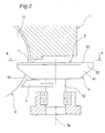
Fig. 2 is an enlarged sectional view of the screw compressor; -
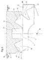
Fig. 3 is a view taken along the line A-A ofFig. 2 ; -
Fig. 4 is an enlarged sectional view of a screw compressor according to a prior art; -
Fig. 5 is a view taken along the line B-B ofFig. 4 ; -
Fig. 6 is a cross-sectional view showing another embodiment of the screw compressor according to the present invention; and -
Fig. 7 is an enlarged sectional view ofFig. 6 . - Hereinbelow, the present invention will be described in detail by way of embodiments thereof illustrated in the accompanying drawings.
-
Fig. 1 is a cross-sectional view showing an embodiment of a screw compressor according to the invention. This screw compressor is a single screw compressor, which includes acasing 1 having acylinder 10, a cylindrical-shaped screw rotor 2 fitted to thecylinder 10, and agate rotor 3 engaged with thescrew rotor 2. - The
screw rotor 2 has, on its outer peripheral surface, a plurality of spiral-shaped groove portions 21. Thegate rotor 3 is disc-shaped and has, on its outer peripheral surface, a plurality oftooth portions 31 in a gear-like form. Thegroove portions 21 of thescrew rotor 2 and thetooth portions 31 of thegate rotor 3 are engaged with each other, respectively. - By mutual engagement of the
screw rotor 2 and thegate rotor 3, compression chambers C are defined. That is, these compression chambers C are spaces defined by thegroove portions 21 of thescrew rotor 2, thetooth portions 31 of thegate rotor 3, and an inner surface of thecylinder 10 of thecasing 1. - The
gate rotor 3 is placed in one pair on the right and left hands of thescrew rotor 2 in left-and-right point symmetry with respect to ashaft 2a of thescrew rotor 2. Thecasing 1 has a throughhole 12 extending through thecylinder 10, and thegate rotor 3 is coming into thecylinder 10 through this throughhole 12. - The
screw rotor 2 rotates in an arrow R direction about theshaft 2a, and along with this rotation of thescrew rotor 2, thegate rotor 3 rotates to compress the gas within each of the compression chambers C. Thescrew rotor 2 is rotated by a (not shown) motor housed in thecasing 1. - Into each of the compression chambers C, a low-pressure gas is sucked from the suction side of one end of the
screw rotor 2 in theshaft 2a direction, and the low-pressure gas is compressed in the compression chamber C, and then the compressed high-pressure gas is discharged from adischarge hole 13 provided on the discharge side at the other end of thescrew rotor 2 in theshaft 2a direction. - As shown in an enlarged sectional view of
Fig. 2 andFig. 3 , which is a view taken along the line A-A ofFig. 2 , aseal surface 11 of thecasing 1 faces the compression chambers C-side of onesurface 30 of thegate rotor 3. - In
Fig. 3 , left side of thescrew rotor 2 in drawing-sheet is assumed as the suction side for sucking the gas to the compression chambers C, while right side of thescrew rotor 2 in drawing-sheet is assumed as the discharge side for discharging the gas from the compression chambers C. - The
seal surface 11 of thecasing 1 is a surface which adjoins the inner surface of thecylinder 10. Theseal surface 11 of thecasing 1 extends in a direction parallel to theshaft 2a of thescrew rotor 2. - The one
surface 30 of thegate rotor 3 forms part of inner surface of each of the compression chambers C. Between theseal surface 11 of thecasing 1 and the onesurface 30 of thegate rotor 3 is a gap of, for example, about 60 µm. - With regard to the width of the
seal surface 11 of thecasing 1, width on a gas-discharge side of thescrew rotor 2 is larger than width on the gas-suction side of thescrew rotor 2. In addition, with regard to the width of theseal surface 11, width on the gas-discharge side of thescrew rotor 2 may be equal to width on the gas-suction side of thescrew rotor 2. - The
gate rotor 3 is mounted on agate rotor shaft 4. Thegate rotor shaft 4 has abase portion 41, and ashaft portion 42 attached to thebase portion 41. The onesurface 30 of thegate rotor 3 and theother surface 32 are attached to thebase portion 41. - The
base portion 41 has a shape corresponding to the shape of thegate rotor 3. That is, the tooth portions of thebase portion 41 has a shape corresponding to thetooth portions 31 of thegate rotor 3 and also corresponding to a space S between neighboringtooth portions 31. Theshaft portion 42 is supported by thecasing 1. - On the
other surface 32 side of thegate rotor 3 is placed aseal portion 5. That is, theseal portion 5 is faced to theseal surface 11 with thegate rotor 3 and thebase portion 41 interposed therebetween. Theseal portion 5 blocks the space S between neighboringtooth portions 31. - The
seal portion 5 is a platy member fitted to thecasing 1. Theseal portion 5 is slightly apart from thebase portion 41. A material of theseal portion 5 is, for example, polyphenylene sulfide resin. - One
surface 50 of theseal portion 5 is faced to theseal surface 11 with thegate rotor 3 interposed therebetween. The onesurface 50 has a shape substantially corresponding to part of theseal surface 11 faced to theseal portion 5 with thegate rotor 3 interposed therebetween. That is, with regard to the width of the onesurface 50 of theseal portion 5, width on a gas-discharge side of thescrew rotor 2 is larger than width on the gas-suction side of thescrew rotor 2. In addition, with regard to the width of the onesurface 50 of theseal portion 5, width on the gas-discharge side of thescrew rotor 2 may be equal to width on the gas-suction side of thescrew rotor 2. - The
seal portion 5 is provided more on the discharge side in theshaft 2a direction of thescrew rotor 2 than a plane P containing ashaft 3a of thegate rotor 3 and perpendicular to theshaft 2a of thescrew rotor 2. - According to the screw compressor constructed as described above, the
seal portion 5 is placed on theother surface 32 side of thegate rotor 3, and theseal portion 5 blocks the space S between neighboringtooth portions 31. Therefore, theseal portion 5 blocks the gas within each of the compression chambers C from passing through the neighboringtooth portions 31 and going out from the onesurface 30 of thegate rotor 3 to theother surface 32 side. That is, the gas within each of the compression chambers C can be prevented from passing through the neighboringtooth portions 31 and leaking out to the low-pressure space S having thegate rotor 3 housed therein. - Thus, gas leakage from the space S between neighboring
tooth portions 31 of thegate rotor 3 can be reduced, so that the compression performance can be improved. - Also, when the one
surface 50 of theseal portion 5 faced to theseal surface 11 with thegate rotor 3 interposed therebetween has a shape substantially corresponding to the shape of part of theseal surface 11 faced to theseal portion 5 with thegate rotor 3 interposed therebetween, the space S can be blocked so that gas leakage can be prevented efficiently. - Also, the
seal portion 5 is provided more on the discharge side in theshaft 2a direction of thescrew rotor 2 than the plane P containing theshaft 3a of thegate rotor 3 and perpendicular to theshaft 2a of thescrew rotor 2. Thus, theseal portion 5 can be made smaller, so that space for mounting theseal portion 5 can be reduced. - That is, since the gas pressure within the compression chambers C becomes higher on the discharge side of the
screw rotor 2, most of gas leakage passing through the space S is from the discharge side (higher-pressure part in compression chamber C) of thescrew rotor 2, and gas leakage from the suction side (lower-pressure part in compression chamber C) of thescrew rotor 2 is small. Therefore, theseal portion 5 may be provided only on the discharge side (higher-pressure part in compression chamber C) of thescrew rotor 2. - The material of the
seal portion 5 is polyphenylene sulfide resin. Therefore, even if theseal portion 5 is brought into contact with thescrew rotor 2 or thegate rotor shaft 4, theseal portion 5 is cut or chopped off so that mechanical damage thereof can be reduced. - The present invention is not limited to the above-described embodiment. For example, the one
surface 50 of theseal portion 5 may be formed into a shape different from that of theseal surface 11. Theseal portion 5 may be provided also on the suction side in theshaft 2a direction of thescrew rotor 2 than the plane P. Theseal portion 5 may be provided as part of thecasing 1. Further, the material of theseal portion 5 may be other than polyphenylene sulfide resin. The quantity of thegate rotor 3 may be increased or decreased. - As shown in
Figs. 6 and7 , it is also possible that aseal portion 5A is formed into a L-shaped cross section and thisseal portion 5A is mounted with bolts in the vicinity of the throughhole 12 of thecasing 1A. In addition, inFigs. 6 and7 , component members designated by the same reference signs as inFigs. 1 and2 are similar in construction to the component members ofFigs. 1 and2 .
Claims (4)
- A screw compressor comprising:a casing (1) having a cylinder (10);a cylindrical-shaped screw rotor (2) which is fitted to the cylinder (10) and which has a plurality of spiral-shaped groove portions (21) in its outer peripheral surface;a gate rotor (3) having, in its outer peripheral surface, a plurality of tooth portions (31) which are engaged with the groove portions (21) of the screw rotor (2), respectively, to define compression chambers (C); anda seal portion (5) placed not on compression chambers (C)-side of one surface (30) of the gate rotor (3) but on the other surface (32) side of the gate rotor (3) opposite to the one surface (30) side, whereinthe seal portion (5) blocks a space (S) between neighboring tooth portions (31) of the gate rotor (3).
- The screw compressor as claimed in Claim 1, wherein
the casing (1) has a seal surface (11) faced to the one surface (30) of the gate rotor (3), and
one surface (50) of the seal portion (5) faced to the seal surface (11) has a shape substantially corresponding to a shape of part of the seal surface (11) faced to the seal portion (5) with the gate rotor (3) interposed therebetween. - The screw compressor as claimed in Claim 1 or 2, wherein
gas is sucked from a suction side of one end of the screw rotor (2) in its shaft (2a) direction, while the gas within each of the compression chambers (C) is discharged from a discharge side of the other end of the screw rotor (2) in the direction of the shaft (2a), and
the seal portion (5) is provided more on the discharge side in the shaft (2a) direction of the screw rotor (2) than a plane (P) containing a shaft (3a) of the gate rotor (3) and perpendicular to the shaft (2a) of the screw rotor (2). - The screw compressor as claimed in any one of Claims 1 to 3, wherein
a material of the seal portion (5) is polyphenylene sulfide resin.
Applications Claiming Priority (3)
| Application Number | Priority Date | Filing Date | Title |
|---|---|---|---|
| JP2007340540 | 2007-12-28 | ||
| JP2008328297A JP4400689B2 (en) | 2007-12-28 | 2008-12-24 | Screw compressor |
| PCT/JP2008/073759 WO2009084641A1 (en) | 2007-12-28 | 2008-12-26 | Screw compressor |
Publications (2)
| Publication Number | Publication Date |
|---|---|
| EP2236833A1 true EP2236833A1 (en) | 2010-10-06 |
| EP2236833A4 EP2236833A4 (en) | 2014-12-17 |
Family
ID=40824354
Family Applications (1)
| Application Number | Title | Priority Date | Filing Date |
|---|---|---|---|
| EP08867336.3A Withdrawn EP2236833A4 (en) | 2007-12-28 | 2008-12-26 | SCREW COMPRESSOR |
Country Status (5)
| Country | Link |
|---|---|
| US (1) | US20100278678A1 (en) |
| EP (1) | EP2236833A4 (en) |
| JP (1) | JP4400689B2 (en) |
| CN (1) | CN101910639B (en) |
| WO (1) | WO2009084641A1 (en) |
Families Citing this family (2)
| Publication number | Priority date | Publication date | Assignee | Title |
|---|---|---|---|---|
| US9057373B2 (en) | 2011-11-22 | 2015-06-16 | Vilter Manufacturing Llc | Single screw compressor with high output |
| CN110446858B (en) * | 2017-03-21 | 2021-08-03 | 大金工业株式会社 | single screw compressor |
Family Cites Families (14)
| Publication number | Priority date | Publication date | Assignee | Title |
|---|---|---|---|---|
| US2158933A (en) * | 1937-07-26 | 1939-05-16 | Paul E Good | Rotary compressor |
| US3133695A (en) * | 1960-06-22 | 1964-05-19 | Zimmern Fernand | Compressors |
| FR2148677A5 (en) * | 1971-07-30 | 1973-03-23 | Zimmern Bernard | |
| JPS5629119B2 (en) * | 1974-04-03 | 1981-07-06 | ||
| JPS5911759B2 (en) * | 1974-04-15 | 1984-03-17 | 北越工業 (株) | Globoid worm type compressor and expander having pinion teeth assembled so that the whole can be freely displaced in the rotational direction and diametrical direction. |
| US4227867A (en) * | 1978-03-06 | 1980-10-14 | Chicago Pneumatic Tool Company | Globoid-worm compressor with single piece housing |
| JPS6014952Y2 (en) * | 1979-07-11 | 1985-05-11 | 株式会社日本自動車部品総合研究所 | Worm compressor |
| JPH0634636Y2 (en) * | 1987-05-27 | 1994-09-07 | ダイキン工業株式会社 | Compressor protector |
| US5032068A (en) * | 1988-10-25 | 1991-07-16 | Kurherr Waldemar H | Displacement type rotary system steam turbine engine |
| JP3216281B2 (en) * | 1992-12-14 | 2001-10-09 | 松下電器産業株式会社 | Gear pump |
| JPH0959592A (en) * | 1995-08-29 | 1997-03-04 | Denso Corp | Seal member |
| JPH10176682A (en) * | 1996-12-17 | 1998-06-30 | Sanyo Electric Co Ltd | Scroll compressor |
| JP3731399B2 (en) | 1999-08-30 | 2006-01-05 | ダイキン工業株式会社 | Screw compressor |
| JP4211871B2 (en) * | 2007-05-23 | 2009-01-21 | ダイキン工業株式会社 | Screw compressor |
-
2008
- 2008-12-24 JP JP2008328297A patent/JP4400689B2/en not_active Expired - Fee Related
- 2008-12-26 US US12/810,598 patent/US20100278678A1/en not_active Abandoned
- 2008-12-26 CN CN2008801224534A patent/CN101910639B/en not_active Expired - Fee Related
- 2008-12-26 EP EP08867336.3A patent/EP2236833A4/en not_active Withdrawn
- 2008-12-26 WO PCT/JP2008/073759 patent/WO2009084641A1/en not_active Ceased
Non-Patent Citations (2)
| Title |
|---|
| No further relevant documents disclosed * |
| See also references of WO2009084641A1 * |
Also Published As
| Publication number | Publication date |
|---|---|
| WO2009084641A1 (en) | 2009-07-09 |
| CN101910639B (en) | 2012-11-14 |
| EP2236833A4 (en) | 2014-12-17 |
| JP4400689B2 (en) | 2010-01-20 |
| JP2009174523A (en) | 2009-08-06 |
| US20100278678A1 (en) | 2010-11-04 |
| CN101910639A (en) | 2010-12-08 |
Similar Documents
| Publication | Publication Date | Title |
|---|---|---|
| WO2002061283A3 (en) | Scroll vacuum pump with improved performance | |
| US9366253B2 (en) | Scroll compressor and processing method of scroll including a projection on a tip seal and a hole in a tip seal groove | |
| US20100260639A1 (en) | Screw compressor | |
| WO2014061186A1 (en) | Scroll compressor | |
| JP5998012B2 (en) | Scroll type fluid machine | |
| CN1373299A (en) | Vortex compressor | |
| KR101425081B1 (en) | Suction structure of scroll compressor | |
| EP0780576A2 (en) | Scroll fluid apparatus | |
| US20100278678A1 (en) | Screw compressor | |
| KR20060109302A (en) | Electric compressors | |
| CN101668951B (en) | Screw compressor | |
| US20190264688A1 (en) | Scroll compressor | |
| KR100855187B1 (en) | Roots rotor and screw rotor combined dry vacuum pump | |
| JP4821660B2 (en) | Single screw compressor | |
| JP5207822B2 (en) | Screw compressor | |
| US11408422B2 (en) | Scroll compressor having an arcuate portion side surface clearance larger than a spiral portion side surface clearance | |
| JP5759125B2 (en) | Structure of suction part of screw compressor body | |
| JP4847054B2 (en) | Scroll type fluid machine | |
| JP4325702B2 (en) | Screw compressor | |
| EP3557063A1 (en) | Screw compressor | |
| CN1273745C (en) | Gas Compressor | |
| JP2621673B2 (en) | Vane compressor | |
| CN111051697A (en) | gear pump or motor | |
| JPH01267380A (en) | Blade for scroll machine | |
| JP2007162622A (en) | Scroll type fluid machine |
Legal Events
| Date | Code | Title | Description |
|---|---|---|---|
| PUAI | Public reference made under article 153(3) epc to a published international application that has entered the european phase |
Free format text: ORIGINAL CODE: 0009012 |
|
| 17P | Request for examination filed |
Effective date: 20100625 |
|
| AK | Designated contracting states |
Kind code of ref document: A1 Designated state(s): AT BE BG CH CY CZ DE DK EE ES FI FR GB GR HR HU IE IS IT LI LT LU LV MC MT NL NO PL PT RO SE SI SK TR |
|
| AX | Request for extension of the european patent |
Extension state: AL BA MK RS |
|
| DAX | Request for extension of the european patent (deleted) | ||
| A4 | Supplementary search report drawn up and despatched |
Effective date: 20141118 |
|
| RIC1 | Information provided on ipc code assigned before grant |
Ipc: F04C 18/52 20060101AFI20141112BHEP |
|
| GRAP | Despatch of communication of intention to grant a patent |
Free format text: ORIGINAL CODE: EPIDOSNIGR1 |
|
| INTG | Intention to grant announced |
Effective date: 20150224 |
|
| STAA | Information on the status of an ep patent application or granted ep patent |
Free format text: STATUS: THE APPLICATION IS DEEMED TO BE WITHDRAWN |
|
| 18D | Application deemed to be withdrawn |
Effective date: 20150707 |