EP2236640A2 - Multi-component coating deposition - Google Patents
Multi-component coating deposition Download PDFInfo
- Publication number
- EP2236640A2 EP2236640A2 EP10006932A EP10006932A EP2236640A2 EP 2236640 A2 EP2236640 A2 EP 2236640A2 EP 10006932 A EP10006932 A EP 10006932A EP 10006932 A EP10006932 A EP 10006932A EP 2236640 A2 EP2236640 A2 EP 2236640A2
- Authority
- EP
- European Patent Office
- Prior art keywords
- components
- deposition material
- deposition
- vaporizing
- weight
- Prior art date
- Legal status (The legal status is an assumption and is not a legal conclusion. Google has not performed a legal analysis and makes no representation as to the accuracy of the status listed.)
- Withdrawn
Links
- 230000008021 deposition Effects 0.000 title claims description 87
- 238000000576 coating method Methods 0.000 title abstract 2
- 239000011248 coating agent Substances 0.000 title 1
- 239000000463 material Substances 0.000 claims abstract description 86
- 150000002902 organometallic compounds Chemical class 0.000 claims abstract description 31
- 238000000034 method Methods 0.000 claims abstract description 27
- 125000002915 carbonyl group Chemical group [*:2]C([*:1])=O 0.000 claims abstract description 12
- 229910000601 superalloy Inorganic materials 0.000 claims abstract description 9
- 238000005229 chemical vapour deposition Methods 0.000 claims abstract 2
- 238000000151 deposition Methods 0.000 claims description 92
- 230000008016 vaporization Effects 0.000 claims description 19
- 229910052782 aluminium Inorganic materials 0.000 claims description 15
- 229910052804 chromium Inorganic materials 0.000 claims description 14
- 238000010894 electron beam technology Methods 0.000 claims description 13
- 239000003870 refractory metal Substances 0.000 claims description 13
- 229910052719 titanium Inorganic materials 0.000 claims description 13
- 239000000203 mixture Substances 0.000 claims description 11
- 229910052759 nickel Inorganic materials 0.000 claims description 11
- 238000010438 heat treatment Methods 0.000 claims description 10
- 229910052721 tungsten Inorganic materials 0.000 claims description 10
- 229910017052 cobalt Inorganic materials 0.000 claims description 8
- 239000010941 cobalt Substances 0.000 claims description 8
- GUTLYIVDDKVIGB-UHFFFAOYSA-N cobalt atom Chemical compound [Co] GUTLYIVDDKVIGB-UHFFFAOYSA-N 0.000 claims description 8
- 229910052750 molybdenum Inorganic materials 0.000 claims description 7
- 229910052742 iron Inorganic materials 0.000 claims description 6
- 229910045601 alloy Inorganic materials 0.000 claims description 5
- 239000000956 alloy Substances 0.000 claims description 5
- 229910018575 Al—Ti Inorganic materials 0.000 claims description 4
- 238000005328 electron beam physical vapour deposition Methods 0.000 claims description 3
- 229910052702 rhenium Inorganic materials 0.000 claims description 3
- 229910052720 vanadium Inorganic materials 0.000 claims description 3
- 229910052741 iridium Inorganic materials 0.000 claims description 2
- 229910052762 osmium Inorganic materials 0.000 claims description 2
- 229910052697 platinum Inorganic materials 0.000 claims description 2
- 229910052703 rhodium Inorganic materials 0.000 claims description 2
- 229910052707 ruthenium Inorganic materials 0.000 claims description 2
- 229910052714 tellurium Inorganic materials 0.000 claims description 2
- 230000008439 repair process Effects 0.000 abstract description 9
- 230000008569 process Effects 0.000 abstract description 2
- 230000003190 augmentative effect Effects 0.000 abstract 1
- 238000005240 physical vapour deposition Methods 0.000 abstract 1
- PXHVJJICTQNCMI-UHFFFAOYSA-N nickel Substances [Ni] PXHVJJICTQNCMI-UHFFFAOYSA-N 0.000 description 14
- 239000011651 chromium Substances 0.000 description 12
- 239000010936 titanium Substances 0.000 description 12
- 229910052799 carbon Inorganic materials 0.000 description 11
- 239000000758 substrate Substances 0.000 description 10
- 238000010494 dissociation reaction Methods 0.000 description 7
- 230000005593 dissociations Effects 0.000 description 7
- XEEYBQQBJWHFJM-UHFFFAOYSA-N iron Substances [Fe] XEEYBQQBJWHFJM-UHFFFAOYSA-N 0.000 description 7
- 229910052751 metal Inorganic materials 0.000 description 7
- 239000002184 metal Substances 0.000 description 7
- 229910001069 Ti alloy Inorganic materials 0.000 description 3
- 238000001704 evaporation Methods 0.000 description 3
- 230000008020 evaporation Effects 0.000 description 3
- 239000012535 impurity Substances 0.000 description 3
- 238000003466 welding Methods 0.000 description 3
- VYZAMTAEIAYCRO-UHFFFAOYSA-N Chromium Chemical compound [Cr] VYZAMTAEIAYCRO-UHFFFAOYSA-N 0.000 description 2
- RTAQQCXQSZGOHL-UHFFFAOYSA-N Titanium Chemical compound [Ti] RTAQQCXQSZGOHL-UHFFFAOYSA-N 0.000 description 2
- 229910008940 W(CO)6 Inorganic materials 0.000 description 2
- XAGFODPZIPBFFR-UHFFFAOYSA-N aluminium Chemical compound [Al] XAGFODPZIPBFFR-UHFFFAOYSA-N 0.000 description 2
- 238000009792 diffusion process Methods 0.000 description 2
- 238000007599 discharging Methods 0.000 description 2
- 230000004907 flux Effects 0.000 description 2
- 238000007689 inspection Methods 0.000 description 2
- 150000002500 ions Chemical class 0.000 description 2
- 238000002156 mixing Methods 0.000 description 2
- 238000000926 separation method Methods 0.000 description 2
- 239000000126 substance Substances 0.000 description 2
- XLYOFNOQVPJJNP-UHFFFAOYSA-N water Substances O XLYOFNOQVPJJNP-UHFFFAOYSA-N 0.000 description 2
- OKTJSMMVPCPJKN-UHFFFAOYSA-N Carbon Chemical compound [C] OKTJSMMVPCPJKN-UHFFFAOYSA-N 0.000 description 1
- UGFAIRIUMAVXCW-UHFFFAOYSA-N Carbon monoxide Chemical compound [O+]#[C-] UGFAIRIUMAVXCW-UHFFFAOYSA-N 0.000 description 1
- RYGMFSIKBFXOCR-UHFFFAOYSA-N Copper Chemical compound [Cu] RYGMFSIKBFXOCR-UHFFFAOYSA-N 0.000 description 1
- 229910017333 Mo(CO)6 Inorganic materials 0.000 description 1
- 229910017709 Ni Co Inorganic materials 0.000 description 1
- 229910003267 Ni-Co Inorganic materials 0.000 description 1
- 229910003262 Ni‐Co Inorganic materials 0.000 description 1
- 230000000903 blocking effect Effects 0.000 description 1
- 229910002091 carbon monoxide Inorganic materials 0.000 description 1
- 238000004891 communication Methods 0.000 description 1
- 150000001875 compounds Chemical class 0.000 description 1
- 238000009833 condensation Methods 0.000 description 1
- 230000005494 condensation Effects 0.000 description 1
- 238000011109 contamination Methods 0.000 description 1
- 238000001816 cooling Methods 0.000 description 1
- 239000012809 cooling fluid Substances 0.000 description 1
- 229910052802 copper Inorganic materials 0.000 description 1
- 239000010949 copper Substances 0.000 description 1
- 230000007547 defect Effects 0.000 description 1
- 238000005137 deposition process Methods 0.000 description 1
- 238000003795 desorption Methods 0.000 description 1
- 239000006185 dispersion Substances 0.000 description 1
- 238000005516 engineering process Methods 0.000 description 1
- 230000003628 erosive effect Effects 0.000 description 1
- 239000011888 foil Substances 0.000 description 1
- 239000000446 fuel Substances 0.000 description 1
- 229910052735 hafnium Inorganic materials 0.000 description 1
- 239000013529 heat transfer fluid Substances 0.000 description 1
- 238000003780 insertion Methods 0.000 description 1
- 230000037431 insertion Effects 0.000 description 1
- 230000008018 melting Effects 0.000 description 1
- 238000002844 melting Methods 0.000 description 1
- 230000005499 meniscus Effects 0.000 description 1
- 238000012986 modification Methods 0.000 description 1
- 230000004048 modification Effects 0.000 description 1
- 238000012544 monitoring process Methods 0.000 description 1
- 229910052758 niobium Inorganic materials 0.000 description 1
- 125000002524 organometallic group Chemical group 0.000 description 1
- 230000000704 physical effect Effects 0.000 description 1
- 238000002360 preparation method Methods 0.000 description 1
- 230000000750 progressive effect Effects 0.000 description 1
- 238000000197 pyrolysis Methods 0.000 description 1
- 230000005855 radiation Effects 0.000 description 1
- 239000007921 spray Substances 0.000 description 1
- 239000010935 stainless steel Substances 0.000 description 1
- 229910001220 stainless steel Inorganic materials 0.000 description 1
- 229910052715 tantalum Inorganic materials 0.000 description 1
- 238000013519 translation Methods 0.000 description 1
- 238000009834 vaporization Methods 0.000 description 1
Images
Classifications
-
- C—CHEMISTRY; METALLURGY
- C23—COATING METALLIC MATERIAL; COATING MATERIAL WITH METALLIC MATERIAL; CHEMICAL SURFACE TREATMENT; DIFFUSION TREATMENT OF METALLIC MATERIAL; COATING BY VACUUM EVAPORATION, BY SPUTTERING, BY ION IMPLANTATION OR BY CHEMICAL VAPOUR DEPOSITION, IN GENERAL; INHIBITING CORROSION OF METALLIC MATERIAL OR INCRUSTATION IN GENERAL
- C23C—COATING METALLIC MATERIAL; COATING MATERIAL WITH METALLIC MATERIAL; SURFACE TREATMENT OF METALLIC MATERIAL BY DIFFUSION INTO THE SURFACE, BY CHEMICAL CONVERSION OR SUBSTITUTION; COATING BY VACUUM EVAPORATION, BY SPUTTERING, BY ION IMPLANTATION OR BY CHEMICAL VAPOUR DEPOSITION, IN GENERAL
- C23C14/00—Coating by vacuum evaporation, by sputtering or by ion implantation of the coating forming material
- C23C14/06—Coating by vacuum evaporation, by sputtering or by ion implantation of the coating forming material characterised by the coating material
- C23C14/14—Metallic material, boron or silicon
- C23C14/16—Metallic material, boron or silicon on metallic substrates or on substrates of boron or silicon
-
- B—PERFORMING OPERATIONS; TRANSPORTING
- B23—MACHINE TOOLS; METAL-WORKING NOT OTHERWISE PROVIDED FOR
- B23P—METAL-WORKING NOT OTHERWISE PROVIDED FOR; COMBINED OPERATIONS; UNIVERSAL MACHINE TOOLS
- B23P6/00—Restoring or reconditioning objects
- B23P6/002—Repairing turbine components, e.g. moving or stationary blades, rotors
- B23P6/007—Repairing turbine components, e.g. moving or stationary blades, rotors using only additive methods, e.g. build-up welding
-
- C—CHEMISTRY; METALLURGY
- C22—METALLURGY; FERROUS OR NON-FERROUS ALLOYS; TREATMENT OF ALLOYS OR NON-FERROUS METALS
- C22C—ALLOYS
- C22C19/00—Alloys based on nickel or cobalt
- C22C19/03—Alloys based on nickel or cobalt based on nickel
- C22C19/05—Alloys based on nickel or cobalt based on nickel with chromium
-
- C—CHEMISTRY; METALLURGY
- C23—COATING METALLIC MATERIAL; COATING MATERIAL WITH METALLIC MATERIAL; CHEMICAL SURFACE TREATMENT; DIFFUSION TREATMENT OF METALLIC MATERIAL; COATING BY VACUUM EVAPORATION, BY SPUTTERING, BY ION IMPLANTATION OR BY CHEMICAL VAPOUR DEPOSITION, IN GENERAL; INHIBITING CORROSION OF METALLIC MATERIAL OR INCRUSTATION IN GENERAL
- C23C—COATING METALLIC MATERIAL; COATING MATERIAL WITH METALLIC MATERIAL; SURFACE TREATMENT OF METALLIC MATERIAL BY DIFFUSION INTO THE SURFACE, BY CHEMICAL CONVERSION OR SUBSTITUTION; COATING BY VACUUM EVAPORATION, BY SPUTTERING, BY ION IMPLANTATION OR BY CHEMICAL VAPOUR DEPOSITION, IN GENERAL
- C23C14/00—Coating by vacuum evaporation, by sputtering or by ion implantation of the coating forming material
- C23C14/04—Coating on selected surface areas, e.g. using masks
- C23C14/042—Coating on selected surface areas, e.g. using masks using masks
-
- C—CHEMISTRY; METALLURGY
- C23—COATING METALLIC MATERIAL; COATING MATERIAL WITH METALLIC MATERIAL; CHEMICAL SURFACE TREATMENT; DIFFUSION TREATMENT OF METALLIC MATERIAL; COATING BY VACUUM EVAPORATION, BY SPUTTERING, BY ION IMPLANTATION OR BY CHEMICAL VAPOUR DEPOSITION, IN GENERAL; INHIBITING CORROSION OF METALLIC MATERIAL OR INCRUSTATION IN GENERAL
- C23C—COATING METALLIC MATERIAL; COATING MATERIAL WITH METALLIC MATERIAL; SURFACE TREATMENT OF METALLIC MATERIAL BY DIFFUSION INTO THE SURFACE, BY CHEMICAL CONVERSION OR SUBSTITUTION; COATING BY VACUUM EVAPORATION, BY SPUTTERING, BY ION IMPLANTATION OR BY CHEMICAL VAPOUR DEPOSITION, IN GENERAL
- C23C14/00—Coating by vacuum evaporation, by sputtering or by ion implantation of the coating forming material
- C23C14/22—Coating by vacuum evaporation, by sputtering or by ion implantation of the coating forming material characterised by the process of coating
-
- C—CHEMISTRY; METALLURGY
- C23—COATING METALLIC MATERIAL; COATING MATERIAL WITH METALLIC MATERIAL; CHEMICAL SURFACE TREATMENT; DIFFUSION TREATMENT OF METALLIC MATERIAL; COATING BY VACUUM EVAPORATION, BY SPUTTERING, BY ION IMPLANTATION OR BY CHEMICAL VAPOUR DEPOSITION, IN GENERAL; INHIBITING CORROSION OF METALLIC MATERIAL OR INCRUSTATION IN GENERAL
- C23C—COATING METALLIC MATERIAL; COATING MATERIAL WITH METALLIC MATERIAL; SURFACE TREATMENT OF METALLIC MATERIAL BY DIFFUSION INTO THE SURFACE, BY CHEMICAL CONVERSION OR SUBSTITUTION; COATING BY VACUUM EVAPORATION, BY SPUTTERING, BY ION IMPLANTATION OR BY CHEMICAL VAPOUR DEPOSITION, IN GENERAL
- C23C14/00—Coating by vacuum evaporation, by sputtering or by ion implantation of the coating forming material
- C23C14/22—Coating by vacuum evaporation, by sputtering or by ion implantation of the coating forming material characterised by the process of coating
- C23C14/24—Vacuum evaporation
-
- C—CHEMISTRY; METALLURGY
- C23—COATING METALLIC MATERIAL; COATING MATERIAL WITH METALLIC MATERIAL; CHEMICAL SURFACE TREATMENT; DIFFUSION TREATMENT OF METALLIC MATERIAL; COATING BY VACUUM EVAPORATION, BY SPUTTERING, BY ION IMPLANTATION OR BY CHEMICAL VAPOUR DEPOSITION, IN GENERAL; INHIBITING CORROSION OF METALLIC MATERIAL OR INCRUSTATION IN GENERAL
- C23C—COATING METALLIC MATERIAL; COATING MATERIAL WITH METALLIC MATERIAL; SURFACE TREATMENT OF METALLIC MATERIAL BY DIFFUSION INTO THE SURFACE, BY CHEMICAL CONVERSION OR SUBSTITUTION; COATING BY VACUUM EVAPORATION, BY SPUTTERING, BY ION IMPLANTATION OR BY CHEMICAL VAPOUR DEPOSITION, IN GENERAL
- C23C14/00—Coating by vacuum evaporation, by sputtering or by ion implantation of the coating forming material
- C23C14/22—Coating by vacuum evaporation, by sputtering or by ion implantation of the coating forming material characterised by the process of coating
- C23C14/54—Controlling or regulating the coating process
-
- C—CHEMISTRY; METALLURGY
- C23—COATING METALLIC MATERIAL; COATING MATERIAL WITH METALLIC MATERIAL; CHEMICAL SURFACE TREATMENT; DIFFUSION TREATMENT OF METALLIC MATERIAL; COATING BY VACUUM EVAPORATION, BY SPUTTERING, BY ION IMPLANTATION OR BY CHEMICAL VAPOUR DEPOSITION, IN GENERAL; INHIBITING CORROSION OF METALLIC MATERIAL OR INCRUSTATION IN GENERAL
- C23C—COATING METALLIC MATERIAL; COATING MATERIAL WITH METALLIC MATERIAL; SURFACE TREATMENT OF METALLIC MATERIAL BY DIFFUSION INTO THE SURFACE, BY CHEMICAL CONVERSION OR SUBSTITUTION; COATING BY VACUUM EVAPORATION, BY SPUTTERING, BY ION IMPLANTATION OR BY CHEMICAL VAPOUR DEPOSITION, IN GENERAL
- C23C16/00—Chemical coating by decomposition of gaseous compounds, without leaving reaction products of surface material in the coating, i.e. chemical vapour deposition [CVD] processes
- C23C16/44—Chemical coating by decomposition of gaseous compounds, without leaving reaction products of surface material in the coating, i.e. chemical vapour deposition [CVD] processes characterised by the method of coating
Definitions
- the invention relates to the restoration of turbomachine parts. More particularly, the invention relates to the restoration of worn or damaged gas turbine engine blades and other blades and vanes.
- the components of gas turbine engines are subject to wear and damage. Even moderate wear and damage of certain components may interfere with optimal operation of the engine. Particular areas of concern involve the airfoils of various blades and vanes. Wear and damage may interfere with their aerodynamic efficiency, produce dynamic force imbalances, and even structurally compromise the worn/damaged parts in more extreme cases. A limited reconditioning is commonly practiced for slightly worn or damaged airfoils wherein additional material is removed below the wear/damage to provide the airfoil with a relatively efficient and clean sectional profile albeit smaller than the original or prior profile.
- U.S. Patent No. 4,822,248 discloses use of a plasma torch to deposit nickel- or cobalt-based superalloy material.
- U.S. Patent No. 5,732,467 identifies the use of high velocity oxy-fuel (HVOF) and low pressure plasma spray (LPPS) techniques for repairing cracks in such turbine elements.
- HVOF high velocity oxy-fuel
- LPPS low pressure plasma spray
- U.S. Patent No. 5,783,318 also identifies LPPS techniques in addition to laser welding and plasma transferred arc welding.
- U.S. Patent No. 6,049,978 identifies further use of HVOF techniques. Such techniques have offered a limited ability to build up replacement material to restore an original or near original cross-section. However, the structural properties of the replacement material may be substantially limited relative to those of the base material.
- One aspect of the invention involves a method for depositing a deposition material on a part.
- the part is placed in a deposition chamber.
- One or more first components for forming the deposition material are vaporized by electron beam heating.
- One or more organometallic compounds are vaporized for providing one or more second components of the deposition material being co-deposited on the part with the first components.
- evaporated components of the deposition material may be ionized.
- the ionization may be via pulse-modulated ion-enhanced EBPVD.
- the temperature of the part may be actively controlled to, in turn, control dissociation of the one or more organometallic compounds.
- the part may subsequently be heat treated so as to homogenize the deposited deposition material.
- the temperature of the part may be maintained between 600°C and 1050°C, more narrowly 600°C and 900°C.
- the vaporizing of the one or more organometallic compounds may comprise heating to between 45°C and 120°C, more narrowly, 50C and 80C.
- the one or more organometallic compounds may comprise, at least 50%, carbonyls of one or more refractory elements.
- the vaporizing of the one or more first components may comprise vaporizing at least one M-Cr-AI-Ti alloy and the deposition material may consist essentially of a nickel- or cobalt-based superalloy.
- the one or more first components may consist in major part of Ti and the one or more second components may consist essentially of Mo.
- the deposition material may consist essentially of at least one of a nickel-or cobalt-based superalloy with 2-20% refractory metal addition.
- the deposition material may consist essentially of: at least one M-Cr-AI-Ti alloy; 2-20% combined of one or more of W, Mo, Re, Pt, Rh, Ru, Os, Ir, Te, and V; and 0-0.3% C.
- the part may have lost first material from a site and the deposition material may be deposited to the site so as to restore the part.
- the deposition material may have a first interface with a substrate of the part, a bond strength between the deposition material and the substrate being in excess of 50 ksi (e.g., between 60 ksi and 90 ksi).
- the part and the deposition material may comprise nickel- or cobalt-based superalloys of like nominal composition and having 2-20% refractory metal
- the substrate may have a thickness in excess of the depth of the deposition material.
- the substrate may comprise original unrepaired material.
- the deposition material may have a depth of at least 2.0 mm at the site (e.g., in a localized foreign object damage repair situation).
- the deposition material may have an average depth of less than 0.75 mm. A maximum depth may also be similarly small (e.g., in an erosion-only repair situation).
- a mask may be applied to a portion of the part surrounding the site prior to deposition and the mask may be removed after the deposition.
- the vaporized one or more organometallic compounds may be permitted to condense on the part and the deposition surface on the part may be irradiated via an electron beam to cause non-thermal dissociation of the one or more organometallic compounds leaving one or more refractory metals as said one or more second components.
- a deposition chamber contains the workpiece.
- the means for vaporizing the one or more first deposition material components may comprise an electron beam source directing an electron beam toward an ingot comprising the one or more first deposition material components and lacking ion-enhancement.
- the means for vaporizing the one or more organometallic compounds may comprise a conductive heater for heating the one or more organometallic compounds.
- the control system may be programmed to provide a progressively varying balance between the one or more first deposition material components and the one or more second deposition material components across a thickness of the deposited material so as to form a predetermined graded composition in the deposited material.
- a deposition chamber contains the workpiece.
- a first source of one or more first components of the deposition material is heated so as to vaporize the first components.
- a second source comprising one or more organometallic compounds provides one or more second components of the deposition material.
- the one or more first components may include:
- Another aspect of the invention involves a method for codepositing one or more first components and one or more second components.
- the one or more first components are electron beam physical vapor deposited.
- the one or more second components are chemical vapor deposited from an organometallic compound.
- the first components may comprise: at least 50% of one or a combination of Ni, Co, and Fe; at least 12% Cr; at least 6% Al; and at least 0.5% Ti.
- the one or more first components may be from a single ingot.
- the one or more second components may be at least two refractory metal components from at least two different sources of different composition.
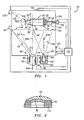
- FIG. 1 shows a blade 20 from a gas turbine engine.
- the blade has an inboard blade root 22 configured for attaching the blade to a disk (not shown).
- a platform 24 separates the blade root from an airfoil 26 extending from the platform to a tip 28.
- the airfoil has a leading edge 30 and a trailing edge 32 with suction and pressure sides extending therebetween.
- FIG. 1 shows the airfoil having localized damage such as is associated with foreign object damage (FOD) nicking or chipping the airfoil proximate the leading edge to create a damaged leading portion 30'.
- FOD foreign object damage
- the damage site is advantageously cleaned of contamination. Further removal of base material may provide an advantageous base surface for receiving deposition.
- the remaining base material of the blade may be locally or broadly ground to a preset configuration such as providing an angled leading facet or base surface as in U.S. patent application 10/635,694 ( US Published Application 2004/0172825 ) (the '694 application).
- a mask element 40 ( FIG. 2 ) is secured to the airfoil surrounding the damaged leading edge portion 30'.
- the mask may be a metallic (e.g., stainless steel) foil.
- a scaffold/mask may be used as in the '694 application.
- the mask may be spaced-apart from the adjacent surface of the airfoil.
- the blade may then be positioned in a chamber 50 of a deposition apparatus 52.
- the blade is held by a clamp 54 at the distal end of a shaft 56 whose proximal end is connected to a drive motor 58.
- the exemplary clamp engages the blade root 22.
- the motor 58 may selectively rotate the blade about an axis 500 in a direction 502 or opposite thereto.
- Alternative holding means may be provided including fixed fixtures and means with other forms of rotation, translation, or more complex movement.
- An exemplary deposition material source 60 takes the form of first and second sources 62 and 64 of first and second deposition material components, respectively.
- the first source may operate in a similar fashion to those shown in the US patent applications 10/377,954 ( US Published Application 2004/0172827 ), 10/635,694 ( US Published Application 2004/0172825 ), 10/734,696 ( US Published Application 2004/0172826 ), and 10/804,754 .
- the exemplary illustrated first source 62 comprises a crucible 65 having at least a first end exposed to an interior of the chamber 50.
- An ingot 66 is progressively fed through the crucible along a direction of insertion 504 (parallel to a first source axis 506) toward the vessel interior.
- the ingot and its progressive movement actuator may be located within the chamber 50.
- the inboard end of the ingot 66 becomes positioned within the crucible 65 along a bottom one of the walls defining the chamber.
- a molten pool 70 of metal from the ingot is formed within the crucible and has a surface or meniscus 72.
- the ingot is melted to provide the pool via an electron beam 76 emitted from an electron gun 78 which may be positioned within or without the chamber to direct the beam to the inboard ingot end/pool.
- the crucible serves to contain the pool.
- the crucible is advantageously cooled to keep it from melting (e.g., by passing a cooling fluid such as water through an external cooling jacket 80).
- the heating by the electron beam is effective to vaporize the metal in the pool.
- the kinetics of the vaporization may be effective to direct a flow 90 of metal vapor from the surface 72 toward the blade.
- the exemplary flow 90 is centered on the axis 506.
- the exemplary ingot materials are alloys mainly comprising one or more of nickel, cobalt and iron with chromium; aluminum; and titanium commonly identified as M-Cr-Al-Ti.
- nickel-based superalloys having concentrations of: cobalt and/or iron; chromium; and aluminum commonly identified as Ni-Co(Fe)-Cr-Al-Ti alloys may be used.
- Titanium-based alloys, including concentrations of Al and V may alternatively be used.
- Exemplary organometallic compounds include carbonyls of the refractory metal(s) (e.g., W(CO) 6 , Mo(CO) 6 , and Re 2 (CO) 10 .
- the vessel may be heated (e.g., to 45-120°C, more narrowly 50-80°C) to vaporize the carbonyl molecules and has a discharge valve 103 with an outlet 104 positioned to direct an outlet flow 106 of the carbonyl vapor toward the blade.
- the discharge valve may be positioned to permit refilling of the second source without releasing the chamber vacuum.
- an elongate discharge conduit carrying the discharge valve may extend from the vessel and penetrate the chamber.
- the exemplary flow 106 has a centerline/axis 508 which may be parallel to the axis 506 or convergent therewith toward the blade 20. Simultaneous deposition of material from the metal and carbonyl flows occurs over a desired coverage area of the blade. The flows mix by free molecular dispersion or by diffusion depending on evaporation rates. In the illustrated embodiment, the exemplary flows of the first component and the carbonyls individually diverge to form a pair of plumes. The plumes may, advantageously, converge relative to each other with diffusion mixing so as to so as to overlap at least along a desired coverage area of the blade. The flows gradually build up a deposition material layer 110 on the desired surface of the blade and on the mask.
- the blade may be continuously or reciprocally rotated for evenness of coverage or to deposit at multiple sites.
- the carbon monoxide of the carbonyls is removed from the deposition material surface in the form of a gas, largely leaving the refractory metal(s) as the second component(s).
- the blade temperature is kept high enough to provide the corresponding necessary minimum temperature level for such evaporation.
- Control of the carbon content of the deposition material may be achieved by ionization of the deposition material components and hence by partial dissociation of the OMCs before reaching the deposition surface. The ionization may reduce defects and increase deposition material density.
- the heating may be achieved by an electron beam 120 delivered by a second electron gun 122.
- the blade temperature may be measured such as by a remote temperature sensor 124 (e.g., an infrared sensor) or a contact sensor 126 (e.g., a thermocouple).
- a remote temperature sensor 124 e.g., an infrared sensor
- a contact sensor 126 e.g., a thermocouple
- Such sensors may be connected via appropriate communication lines to a control system 130 which may also be connected to the electron guns, the sources, and the motor.
- the control system 130 may be connected to other equipment such as a vacuum pump 132 for maintaining a vacuum within the chamber and additional sensors such as a chamber pressure sensor 134.
- Mass flow control for the carbonyl flow may be achieved by throttling of the discharge valve under control of the control system.
- the control system may be programmed to provide feedback loop control of the deposition process. This may include absolute and relative deposition rates of individual components and of other properties (e.g.
- the feedback loop may be responsive to various directly measured and/or calculated parameters.
- the system may be programmed to maintain a constant rate of organometallic compound evaporation.
- the flow rate of evaporated organometallic compounds can be measured by a flow metering system (e.g., using a conventional calorimetric system).
- the control system may use a flux value (e.g., liters per minute) to vary the CVD source temperature so as to maintain a desired balance between EBPVD and CVD fluxes to maintain a fixed deposition material chemistry.
- a composition gradient may be imposed across all or a portion of the deposition material depth.
- a shutter system 140 may have a first position (solid line) clear of the flowpaths from the sources to the blade and a second position (broken line) 140' blocking the flowpaths.
- the shutter may be in the second position during preparation as the apparatus is brought up to initial target operating conditions.
- the ingot material is melted to form the pool
- the OMC is heated to a target operating temperature range with the discharge valve 103 closed
- the blade may be preheated to a target operating temperature range by the second electron gun (e.g., with the beam 120).
- the preheating may serve to clean the deposition surface by pyrolysis and desorption of surface impurities.
- the shutter and discharge valve are opened to expose the blade to deposition.
- the blade may be heated by the second electron gun 122 by heat radiation (e.g., from the melted metal in the pool), and by the latent heat of condensation.
- the second electron gun is turned off if the temperature exceeds the maximum of an operational target range and may be turned off so long as the temperature is within the target range. It may, however, be switched back on if the temperature falls below a minimum of the target range.
- a post-deposition heat treatment may further homogenize the deposition material and integrate the deposition material with the substrate.
- the exemplary ingot is a 70mm diameter right circular cylinder of 59% Ni, 15% Cr, 12% Co, 9% Al, 3% Ti alloy.
- the electron gun heating the ingot is operated at 20kV and 1.9A.
- W(CO) 6 OMC is heated in a copper vessel by 65°C circulating water.
- the vessel outlet is a 6mm diameter circular orifice.
- the source centerline separation is 150mm.
- the source-substrate separation is 300mm.
- the substrate receiving the deposition is alternatively formed of 15.7% Cr, 11 % Co, 1.5% Mo, 5.5% W, 2.7% Al, 4.7% Ti, 0.2% Nb, 0.1% C, remainder Ni plus impurities and 5.5% Cr, 10.3%Co, 1.6%Mo, 5.5%W, 8.4% Ta, 2.4% Re, 6.5%Al, 0.05%Ti, 0.03% Hf, 0.1 % C, remainder Ni plus impurities, nominal composition by weight.
- the substrate temperature is maintained at a nominal 850C. Deposition material composition exactly between the centerlines was measured as 65.0% Ni, 19.1 % Cr, 6.6% Al, 8.0% W, 0.09% C.
- Deposition material composition at the first source centerline was measured as 58.0% Ni, 14.2% Cr, 11.5% Co, 8.9% Al, 2.7% Ti, 3.0% W, 0.13% C.
- Deposition material composition at the second source centerline was measured as 53.1 % Ni, 10.6% Cr, 6.8% Al, 2.3% Ti, 13.2% W, 0.15% C.
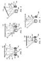
- FIG. 3 shows the addition of a third source 200 which may be added to the first source 62 and the second source 64.
- the third source 200 may be similar to the second source 64 but containing a different organometallic compound 202 and discharging a flow 204 of that compound along an axis 510.
- FIG. 3 more generically shows the workpiece as a plate 210 instead of the blade.
- the workpiece receives a deposition material 212 atop its exposed surface 214.
- the deposition material includes first components from the first source 62 and second components from the second and third sources 64 and 200.
- the exemplary materials deposited by such a system include superalloys with substantial concentrations of W and Mo simultaneously (e.g., at least 2%).
- One exemplary specific deposition material is 52.8% Ni, 15.0% Cr, 7.0% Al, 2.0% Ti, 8.2% W, 4.1% Mo, 0.16% C.
- the second and third sources may be of similar material to provide deposition evenness.
- FIG. 4 shows a system similar to that of FIGS. 1 and 3 but wherein the second source 220 is formed having an annular discharge manifold 222 encircling the flow from the first source 62 and having an outlet 224 in the form of an annular slot or an annular aperture/nozzle array discharging an initially annular flow 226 of the organometallic vapor.
- the manifold is coupled to the vessel 230 by a conduit/tube 232.
- the annular flow collapses as flow portions from diametrically opposite portions of the manifold merge along a system centerline coincident with a centerline of the first source 62 and its flow.
- FIG. 5 shows an alternate system wherein the workpiece 210 is held at an angle off-normal to the first source centerline.
- the second source 240 has a short discharge conduit 242 extending from the outlet of the vessel 244.
- the second source flow 246 has a centerline/axis 520 intersecting the first source centerline/axis for better flow overlap at the workpiece.
- FIG. 6 shows an alternate system wherein the second source 250 discharges its flow coaxially within the metal vapor flow. Its elongate outlet conduit 252 extends within the metal vapor flow so that a carbonyl exiting the outlet 254 of the conduit 252 becomes entrained in the flow from the first source. Such a system may provide a more intimate and homogenous mixing of flows from the two sources. Alternatively the outlet 254 may be positioned within the first source flow but directed so that its own flow centerline is parallel/offset or converging with the first source flow centerline.
- FIG. 7 shows a system wherein the second source 280 discharges an OMC flow 282 from a supersonic nozzle 284.
- the flow 282 has a centerline 540 which, in the exemplary embodiment, is off-parallel to and intersecting with the first source centerline.
- Such a system may provide a collimation of the second source flow.
- the second source flow may be more narrow or wide in accordance with the workpiece dimensions.
- One more alternate system may comprise irradiation of the deposition surface by an electron beam to cause electron beam-induced dissociation of the one or more organometallic compounds for providing one or more second components of the deposition material.
- Such non-thermal dissociation may be performed with or instead thermal dissociation and may provide control of dissociation range.
- Exemplary process parameters may vary based upon the substrate material, deposition material, substrate geometry, and apparatus capacities.
- an operating temperature of the part may be 800-1050°C, more narrowly 850-1000°C.
- Carbonyl source temperature may be 45-90°C, more narrowly 50-75°C.
- Electron beam current may be 1.7-2.5A, more narrowly 1.8-2.2A.
- Chamber pressures may be less than 0.01 Pa.
- Deposition rates may be 5-30 ⁇ m/min, more narrowly 15-20 ⁇ m/min.
Landscapes
- Chemical & Material Sciences (AREA)
- Engineering & Computer Science (AREA)
- Mechanical Engineering (AREA)
- Materials Engineering (AREA)
- Metallurgy (AREA)
- Organic Chemistry (AREA)
- Chemical Kinetics & Catalysis (AREA)
- General Chemical & Material Sciences (AREA)
- Physical Vapour Deposition (AREA)
- Chemical Vapour Deposition (AREA)
- Turbine Rotor Nozzle Sealing (AREA)
Abstract
Description
- The invention relates to the restoration of turbomachine parts. More particularly, the invention relates to the restoration of worn or damaged gas turbine engine blades and other blades and vanes.
- The components of gas turbine engines are subject to wear and damage. Even moderate wear and damage of certain components may interfere with optimal operation of the engine. Particular areas of concern involve the airfoils of various blades and vanes. Wear and damage may interfere with their aerodynamic efficiency, produce dynamic force imbalances, and even structurally compromise the worn/damaged parts in more extreme cases. A limited reconditioning is commonly practiced for slightly worn or damaged airfoils wherein additional material is removed below the wear/damage to provide the airfoil with a relatively efficient and clean sectional profile albeit smaller than the original or prior profile. Exemplary inspection criteria establishing the limits to which such reconditioning can be made are shown in Pratt & Whitney JT8D Engine Manual (P/N 773128), ATA 72-33-21, Inspection - 01, United Technologies Corp., East Hartford Connecticut. Such limits may differ among airfoils depending upon the location and particular application. The limits are typically based on structural and performance considerations which limit the amount of material that may be removed.
- Various techniques have been proposed for more extensive restoration of worn or damaged parts of gas turbine engines.
U.S. Patent No. 4,822,248 discloses use of a plasma torch to deposit nickel- or cobalt-based superalloy material.U.S. Patent No. 5,732,467 identifies the use of high velocity oxy-fuel (HVOF) and low pressure plasma spray (LPPS) techniques for repairing cracks in such turbine elements.U.S. Patent No. 5,783,318 also identifies LPPS techniques in addition to laser welding and plasma transferred arc welding.U.S. Patent No. 6,049,978 identifies further use of HVOF techniques. Such techniques have offered a limited ability to build up replacement material to restore an original or near original cross-section. However, the structural properties of the replacement material may be substantially limited relative to those of the base material. - Especially for larger damage, it is known to use preformed inserts which may be welded in place to repair damage. With such inserts, the damaged area is cut away to the predetermined shape of the insert which is, in turn, welded in place. Structural limits associated with the welding limit the capability of such repair techniques to relatively low stress regions of the airfoil as with other techniques. It is common for engine repair manuals to specify the low stress areas where weld repair is permissible. Thus substantial combinations of the extent of the wear/damage and the stress to which the worn/damaged area is subject may limit use of such techniques.
- One aspect of the invention involves a method for depositing a deposition material on a part. The part is placed in a deposition chamber. One or more first components for forming the deposition material are vaporized by electron beam heating. One or more organometallic compounds are vaporized for providing one or more second components of the deposition material being co-deposited on the part with the first components.
- In various implementations, evaporated components of the deposition material may be ionized. The ionization may be via pulse-modulated ion-enhanced EBPVD. The temperature of the part may be actively controlled to, in turn, control dissociation of the one or more organometallic compounds. The part may subsequently be heat treated so as to homogenize the deposited deposition material. The temperature of the part may be maintained between 600°C and 1050°C, more narrowly 600°C and 900°C. The vaporizing of the one or more organometallic compounds may comprise heating to between 45°C and 120°C, more narrowly, 50C and 80C. The one or more organometallic compounds may comprise, at least 50%, carbonyls of one or more refractory elements. The vaporizing of the one or more first components may comprise vaporizing at least one M-Cr-AI-Ti alloy and the deposition material may consist essentially of a nickel- or cobalt-based superalloy. The one or more first components may consist in major part of Ti and the one or more second components may consist essentially of Mo. The deposition material may consist essentially of at least one of a nickel-or cobalt-based superalloy with 2-20% refractory metal addition. The deposition material may consist essentially of: at least one M-Cr-AI-Ti alloy; 2-20% combined of one or more of W, Mo, Re, Pt, Rh, Ru, Os, Ir, Te, and V; and 0-0.3% C.
- The part may have lost first material from a site and the deposition material may be deposited to the site so as to restore the part. The deposition material may have a first interface with a substrate of the part, a bond strength between the deposition material and the substrate being in excess of 50 ksi (e.g., between 60 ksi and 90 ksi). The part and the deposition material may comprise nickel- or cobalt-based superalloys of like nominal composition and having 2-20% refractory metal The substrate may have a thickness in excess of the depth of the deposition material. The substrate may comprise original unrepaired material. The deposition material may have a depth of at least 2.0 mm at the site (e.g., in a localized foreign object damage repair situation). The deposition material may have an average depth of less than 0.75 mm. A maximum depth may also be similarly small (e.g., in an erosion-only repair situation). A mask may be applied to a portion of the part surrounding the site prior to deposition and the mask may be removed after the deposition. The vaporized one or more organometallic compounds may be permitted to condense on the part and the deposition surface on the part may be irradiated via an electron beam to cause non-thermal dissociation of the one or more organometallic compounds leaving one or more refractory metals as said one or more second components.
- Another aspect of the invention involves an apparatus for depositing material on a workpiece. A deposition chamber contains the workpiece. There are means for vaporizing one or more first deposition material components. There are means for vaporizing one or more organometallic compounds for providing one or more second deposition material components;. There is a control system coupled to the means for vaporizing one or more first deposition material components and the means for vaporizing one or more organometallic compounds and programmed so as to provide feedback loop control of codeposition of the first and second deposition material components to the workpiece.
- In various implementations, there may be means for monitoring a temperature of the workpiece. There may be means for generating a plasma from one or more of the vaporized first deposition material components and/or the organometallic compounds. There may be means for applying a modulated bias electric potential to the workpiece to draw ions from the plasma to the workpiece. The means for vaporizing the one or more first deposition material components may comprise an electron beam source directing an electron beam toward an ingot comprising the one or more first deposition material components and lacking ion-enhancement. The means for vaporizing the one or more organometallic compounds may comprise a conductive heater for heating the one or more organometallic compounds. The control system may be programmed to provide a progressively varying balance between the one or more first deposition material components and the one or more second deposition material components across a thickness of the deposited material so as to form a predetermined graded composition in the deposited material.
- Another aspect of the invention involves an apparatus for depositing deposition material on a workpiece. A deposition chamber contains the workpiece. A first source of one or more first components of the deposition material is heated so as to vaporize the first components. A second source comprising one or more organometallic compounds provides one or more second components of the deposition material.
- In various implementations, the one or more first components may include:
- at least 50% of one or a combination of Ni, Co and Fe; at least 12% Cr; at least 6% Al; and at least 0.5% Ti. The one or more second components may consist essentially of one or more refractory metals and up to 0.3% C. The one or more first components may include at least 50% Ti and the one or more second components may consist essentially of one or more refractory metals and up to 0.1% C.
- Another aspect of the invention involves a method for codepositing one or more first components and one or more second components. The one or more first components are electron beam physical vapor deposited. The one or more second components are chemical vapor deposited from an organometallic compound.
- In various implementations, the first components may comprise: at least 50% of one or a combination of Ni, Co, and Fe; at least 12% Cr; at least 6% Al; and at least 0.5% Ti. The one or more first components may be from a single ingot. The one or more second components may be at least two refractory metal components from at least two different sources of different composition.
- The details of one or more embodiments of the invention are set forth in the accompanying drawings and the description below. Other features and advantages of the invention will be apparent from the description and drawings, and from the claims.
-
FIG. 1 is a partially schematic view of a turbine engine blade in a repair apparatus according to principles of the invention. -
FIG. 2 is a view of a damaged area of the blade ofFIG. 1 . -
FIG. 3 is a partially schematic view of a second deposition apparatus. -
FIG. 4 is a partially schematic view of a third deposition apparatus. -
FIG. 5 is a partially schematic view of a fourth deposition apparatus. -
FIG. 6 is a partially schematic view of a fifth deposition apparatus. -
FIG. 7 is a partially schematic view of a sixth deposition apparatus. - Like reference numbers and designations in the various drawings indicate like elements.
-
FIG. 1 shows ablade 20 from a gas turbine engine. The blade has aninboard blade root 22 configured for attaching the blade to a disk (not shown). Aplatform 24 separates the blade root from anairfoil 26 extending from the platform to atip 28. The airfoil has aleading edge 30 and a trailing edge 32 with suction and pressure sides extending therebetween. -
FIG. 1 shows the airfoil having localized damage such as is associated with foreign object damage (FOD) nicking or chipping the airfoil proximate the leading edge to create a damaged leading portion 30'. Alternatively there may be more general damage such as a broadly-eroded leading edge. The damage site is advantageously cleaned of contamination. Further removal of base material may provide an advantageous base surface for receiving deposition. For example, after the damage/wear, the remaining base material of the blade may be locally or broadly ground to a preset configuration such as providing an angled leading facet or base surface as inU.S. patent application 10/635,694 (US Published Application 2004/0172825 ) (the '694 application). - In an optional illustrated variation, a mask element 40 (
FIG. 2 ) is secured to the airfoil surrounding the damaged leading edge portion 30'. In the exemplary embodiment, the mask may be a metallic (e.g., stainless steel) foil. Alternatively or additionally, a scaffold/mask may be used as in the '694 application. Alternatively, the mask may be spaced-apart from the adjacent surface of the airfoil. - The blade may then be positioned in a
chamber 50 of adeposition apparatus 52. In the exemplary embodiment, the blade is held by aclamp 54 at the distal end of ashaft 56 whose proximal end is connected to adrive motor 58. The exemplary clamp engages theblade root 22. Themotor 58 may selectively rotate the blade about anaxis 500 in adirection 502 or opposite thereto. Alternative holding means may be provided including fixed fixtures and means with other forms of rotation, translation, or more complex movement. An exemplarydeposition material source 60 takes the form of first andsecond sources US patent applications 10/377,954 US Published Application 2004/0172827 ),10/635,694 US Published Application 2004/0172825 ),10/734,696 US Published Application 2004/0172826 ), and10/804,754 first source 62 comprises acrucible 65 having at least a first end exposed to an interior of thechamber 50. Aningot 66 is progressively fed through the crucible along a direction of insertion 504 (parallel to a first source axis 506) toward the vessel interior. - Appropriate seals may be provided to prevent leakage around the ingot. Alternatively, the ingot and its progressive movement actuator (not shown) may be located within the
chamber 50. The inboard end of theingot 66 becomes positioned within thecrucible 65 along a bottom one of the walls defining the chamber. A molten pool 70 of metal from the ingot is formed within the crucible and has a surface ormeniscus 72. The ingot is melted to provide the pool via anelectron beam 76 emitted from anelectron gun 78 which may be positioned within or without the chamber to direct the beam to the inboard ingot end/pool. The crucible serves to contain the pool. The crucible is advantageously cooled to keep it from melting (e.g., by passing a cooling fluid such as water through an external cooling jacket 80). - The heating by the electron beam is effective to vaporize the metal in the pool. The kinetics of the vaporization may be effective to direct a
flow 90 of metal vapor from thesurface 72 toward the blade. Theexemplary flow 90 is centered on theaxis 506. The exemplary ingot materials are alloys mainly comprising one or more of nickel, cobalt and iron with chromium; aluminum; and titanium commonly identified as M-Cr-Al-Ti. For example, nickel-based superalloys having concentrations of: cobalt and/or iron; chromium; and aluminum commonly identified as Ni-Co(Fe)-Cr-Al-Ti alloys may be used. Titanium-based alloys, including concentrations of Al and V may alternatively be used. - A
second source 64 may be used to provide second components that have sufficiently different properties from the first components that attempting to include such second components in the ingot would prevent or hinder deposition in the desired proportions from a single ingot. The exemplary second components include refractory metals. The exemplarysecond source 64 includes avessel 100 containing one or more organometallic compounds (OMCs) 102 comprising the desired refractory elements. An exemplary vessel is double-walled, having a inner chamber containing the OMC and an outer chamber surrounding the inner chamber and containing a flow of a heated heat transfer fluid to heat the inner chamber. Exemplary organometallic compounds include carbonyls of the refractory metal(s) (e.g., W(CO)6, Mo(CO)6, and Re2(CO)10. The vessel may be heated (e.g., to 45-120°C, more narrowly 50-80°C) to vaporize the carbonyl molecules and has adischarge valve 103 with an outlet 104 positioned to direct anoutlet flow 106 of the carbonyl vapor toward the blade. If the second source vessel is at least partially outside the chamber, the discharge valve may be positioned to permit refilling of the second source without releasing the chamber vacuum. For example, an elongate discharge conduit carrying the discharge valve may extend from the vessel and penetrate the chamber. Theexemplary flow 106 has a centerline/axis 508 which may be parallel to theaxis 506 or convergent therewith toward theblade 20. Simultaneous deposition of material from the metal and carbonyl flows occurs over a desired coverage area of the blade. The flows mix by free molecular dispersion or by diffusion depending on evaporation rates. In the illustrated embodiment, the exemplary flows of the first component and the carbonyls individually diverge to form a pair of plumes. The plumes may, advantageously, converge relative to each other with diffusion mixing so as to so as to overlap at least along a desired coverage area of the blade. The flows gradually build up adeposition material layer 110 on the desired surface of the blade and on the mask. In the exemplary embodiment, the blade may be continuously or reciprocally rotated for evenness of coverage or to deposit at multiple sites. Advantageously, the carbon monoxide of the carbonyls is removed from the deposition material surface in the form of a gas, largely leaving the refractory metal(s) as the second component(s). To achieve this, advantageously the blade temperature is kept high enough to provide the corresponding necessary minimum temperature level for such evaporation. Control of the carbon content of the deposition material may be achieved by ionization of the deposition material components and hence by partial dissociation of the OMCs before reaching the deposition surface. The ionization may reduce defects and increase deposition material density. The heating may be achieved by anelectron beam 120 delivered by asecond electron gun 122. The blade temperature may be measured such as by a remote temperature sensor 124 (e.g., an infrared sensor) or a contact sensor 126 (e.g., a thermocouple). Such sensors may be connected via appropriate communication lines to acontrol system 130 which may also be connected to the electron guns, the sources, and the motor. Thecontrol system 130 may be connected to other equipment such as avacuum pump 132 for maintaining a vacuum within the chamber and additional sensors such as achamber pressure sensor 134. Mass flow control for the carbonyl flow may be achieved by throttling of the discharge valve under control of the control system. The control system may be programmed to provide feedback loop control of the deposition process. This may include absolute and relative deposition rates of individual components and of other properties (e.g. temperatures, pressures, and the like) that may influence the chemical and physical properties of the deposited material. The feedback loop may be responsive to various directly measured and/or calculated parameters. For example, the system may be programmed to maintain a constant rate of organometallic compound evaporation. The flow rate of evaporated organometallic compounds can be measured by a flow metering system (e.g., using a conventional calorimetric system). The control system may use a flux value (e.g., liters per minute) to vary the CVD source temperature so as to maintain a desired balance between EBPVD and CVD fluxes to maintain a fixed deposition material chemistry. Alternatively, a composition gradient may be imposed across all or a portion of the deposition material depth. - A
shutter system 140 may have a first position (solid line) clear of the flowpaths from the sources to the blade and a second position (broken line) 140' blocking the flowpaths. The shutter may be in the second position during preparation as the apparatus is brought up to initial target operating conditions. During this stage, the ingot material is melted to form the pool, the OMC is heated to a target operating temperature range with thedischarge valve 103 closed, and the blade may be preheated to a target operating temperature range by the second electron gun (e.g., with the beam 120). The preheating may serve to clean the deposition surface by pyrolysis and desorption of surface impurities. With the parameters in the initial target ranges, the shutter and discharge valve are opened to expose the blade to deposition. During deposition, the blade may be heated by thesecond electron gun 122 by heat radiation (e.g., from the melted metal in the pool), and by the latent heat of condensation. The second electron gun is turned off if the temperature exceeds the maximum of an operational target range and may be turned off so long as the temperature is within the target range. It may, however, be switched back on if the temperature falls below a minimum of the target range. A post-deposition heat treatment may further homogenize the deposition material and integrate the deposition material with the substrate. - The exemplary ingot is a 70mm diameter right circular cylinder of 59% Ni, 15% Cr, 12% Co, 9% Al, 3% Ti alloy. The electron gun heating the ingot is operated at 20kV and 1.9A. W(CO)6 OMC is heated in a copper vessel by 65°C circulating water. The vessel outlet is a 6mm diameter circular orifice. The source centerline separation is 150mm. The source-substrate separation is 300mm. The substrate receiving the deposition is alternatively formed of 15.7% Cr, 11 % Co, 1.5% Mo, 5.5% W, 2.7% Al, 4.7% Ti, 0.2% Nb, 0.1% C, remainder Ni plus impurities and 5.5% Cr, 10.3%Co, 1.6%Mo, 5.5%W, 8.4% Ta, 2.4% Re, 6.5%Al, 0.05%Ti, 0.03% Hf, 0.1 % C, remainder Ni plus impurities, nominal composition by weight. The substrate temperature is maintained at a nominal 850C. Deposition material composition exactly between the centerlines was measured as 65.0% Ni, 19.1 % Cr, 6.6% Al, 8.0% W, 0.09% C. Deposition material composition at the first source centerline was measured as 58.0% Ni, 14.2% Cr, 11.5% Co, 8.9% Al, 2.7% Ti, 3.0% W, 0.13% C. Deposition material composition at the second source centerline was measured as 53.1 % Ni, 10.6% Cr, 6.8% Al, 2.3% Ti, 13.2% W, 0.15% C.
-
FIG. 3 shows the addition of athird source 200 which may be added to thefirst source 62 and thesecond source 64. Thethird source 200 may be similar to thesecond source 64 but containing a differentorganometallic compound 202 and discharging aflow 204 of that compound along anaxis 510.FIG. 3 more generically shows the workpiece as aplate 210 instead of the blade. The workpiece receives adeposition material 212 atop its exposedsurface 214. The deposition material includes first components from thefirst source 62 and second components from the second andthird sources -
FIG. 4 shows a system similar to that ofFIGS. 1 and3 but wherein thesecond source 220 is formed having anannular discharge manifold 222 encircling the flow from thefirst source 62 and having anoutlet 224 in the form of an annular slot or an annular aperture/nozzle array discharging an initiallyannular flow 226 of the organometallic vapor. The manifold is coupled to thevessel 230 by a conduit/tube 232. The annular flow collapses as flow portions from diametrically opposite portions of the manifold merge along a system centerline coincident with a centerline of thefirst source 62 and its flow. -
FIG. 5 shows an alternate system wherein theworkpiece 210 is held at an angle off-normal to the first source centerline. Thesecond source 240 has ashort discharge conduit 242 extending from the outlet of thevessel 244. Thesecond source flow 246 has a centerline/axis 520 intersecting the first source centerline/axis for better flow overlap at the workpiece. -
FIG. 6 shows an alternate system wherein thesecond source 250 discharges its flow coaxially within the metal vapor flow. Itselongate outlet conduit 252 extends within the metal vapor flow so that a carbonyl exiting theoutlet 254 of theconduit 252 becomes entrained in the flow from the first source. Such a system may provide a more intimate and homogenous mixing of flows from the two sources. Alternatively theoutlet 254 may be positioned within the first source flow but directed so that its own flow centerline is parallel/offset or converging with the first source flow centerline. -
FIG. 7 shows a system wherein thesecond source 280 discharges anOMC flow 282 from asupersonic nozzle 284. Theflow 282 has acenterline 540 which, in the exemplary embodiment, is off-parallel to and intersecting with the first source centerline. Such a system may provide a collimation of the second source flow. The second source flow may be more narrow or wide in accordance with the workpiece dimensions. - One more alternate system may comprise irradiation of the deposition surface by an electron beam to cause electron beam-induced dissociation of the one or more organometallic compounds for providing one or more second components of the deposition material. Such non-thermal dissociation may be performed with or instead thermal dissociation and may provide control of dissociation range.
- Exemplary process parameters may vary based upon the substrate material, deposition material, substrate geometry, and apparatus capacities. For an exemplary deposition of an Ni-based material with 11-12% Co, 12-14% Cr, 7-8% Al, 1.5-2.5% Ti, 2-4% Mo, 10-12% W, 0.1-0.3% C, an operating temperature of the part may be 800-1050°C, more narrowly 850-1000°C. Carbonyl source temperature may be 45-90°C, more narrowly 50-75°C. Electron beam current may be 1.7-2.5A, more narrowly 1.8-2.2A. Chamber pressures may be less than 0.01 Pa. Deposition rates may be 5-30 µm/min, more narrowly 15-20 µm/min.
- One or more embodiments of the present invention have been described. Nevertheless, it will be understood that various modifications may be made without departing from the scope of the invention. For example, although particularly useful with high pressure turbine blades, the methods may be applied to other blades and other turbine engine parts and non-turbine parts. Details of the particular turbine engine part or other piece and the particular wear or damage suffered may influence details of any given restoration. The methods and apparatus may be used for various non-repair applications. Accordingly, other embodiments are within the scope of the following claims.
Claims (15)
- A method for depositing a deposition material (110;212) on a part (20;210) comprising:placing the part in a deposition chamber (50);vaporizing one or more first components (66) of the deposition material by electron beam heating; andvaporizing one or more organometallic compounds (102;202) using a conductive heater (100) for providing one or more second components of the deposition material being codeposited on the part with the first components.
- The method of claim 1, wherein the one or more first components (66) and one or more second components (102;202) condense on the part.
- The method of claim 1 or 2, wherein the vaporizing of the one or more organometallic compounds (102;202) comprises heating to between 45°C and 120°C.
- The method of any preceding claim, wherein the one or more organometallic compounds (102;202) comprise, at least 50% by weight, carbonyls of one or more refractory elements.
- The method of any preceding claim wherein:the vaporizing of the one or more first components (66) comprises vaporizing at least one M-Cr-Al-Ti alloy; andthe deposition material consists essentially of a nickel- or cobalt-based superalloy.
- The method of any of claims 1 to 5, wherein:the one or more first components (66) consist in major part of Ti; andthe one or more second components (102;202) consist essentially of Mo.
- The method of any of claims 1 to 5, wherein the deposition material consists essentially of at least one of a nickel-or cobalt-based superalloy with 1-20%, by weight, refractory metal addition.
- The method of any of claims 1 to 5, wherein the deposition material consists essentially of:at least one M-Cr-Al-Ti alloy;2-20%, by weight, combined of one or more of W, Mo, Re, Pt, Rh, Ru, Os, Ir, Te, and V; and0-0.3%, by weight, C.
- The method of any of claims 1 to 5, wherein:the one or more first components include, by weight:at least 50% of one or a combination of Ni, Co and Fe;at least 12% Cr;at least 6% Al; andat least 0.5% Ti; andthe one or more second components consist essentially of one or more refractory metals and up to 0.3%, by weight, C.
- The method of any of claims 1 to 5, wherein:the one or more first components include at least 50%, by weight, Ti; andthe one or more second components consist essentially of one or more refractory metals and up to 0.1 %, by weight, C.
- An apparatus for depositing material (110;212) on a workpiece (20;210) comprising:a deposition chamber (50);means (62) for vaporizing one or more first deposition material components (66);means for vaporizing (64;200;220;240;250;280) one or more organometallic compounds (102;202) for providing one or more second deposition material components; anda control system (130) coupled to the means for vaporizing one or more first deposition material components and the means for vaporizing one or more organometallic compounds and programmed so as to provide feedback loop control of codeposition of the first and second deposition material components to the workpiece;wherein the means for vaporising the one or more first deposition material components comprises an electron beam source (78); and
wherein the means for vaporising the one or more organometallic compounds (102;202) comprises a conductive heater (100) for heating the one or more organometallic compounds. - The apparatus of claim 11, wherein the control system (130) is programmed to provide a varying balance between the one or more first deposition material components and the one or more second deposition material components across a thickness of the deposited material so as to form a predetermined graded composition in the deposited material.
- A method for codepositing one or more first components (66) and one or more second components (102;202) comprising:electron beam physical vapour deposition of the one or more first components; andchemical vapour deposition of the one or more second components from an organometallic compound.
- The method of claim 13, wherein the one or more first components include, by weight:at least 50% of one or a combination of Ni, Co and Fe;at least 12% Cr;at least 6% Al; andat least 0.5% Ti.
- The method of claim 13 or 14, wherein:the one or more first components are from a single ingot (66); andthe one or more second components are at least two refractory metal components from at least two different sources (102,202) of different composition.
Applications Claiming Priority (2)
| Application Number | Priority Date | Filing Date | Title |
|---|---|---|---|
| US10/840,859 US7404986B2 (en) | 2004-05-07 | 2004-05-07 | Multi-component deposition |
| EP05252802A EP1593752B1 (en) | 2004-05-07 | 2005-05-06 | Multi-component coating deposition |
Related Parent Applications (2)
| Application Number | Title | Priority Date | Filing Date |
|---|---|---|---|
| EP05252802A Division-Into EP1593752B1 (en) | 2004-05-07 | 2005-05-06 | Multi-component coating deposition |
| EP05252802.3 Division | 2005-05-06 |
Publications (2)
| Publication Number | Publication Date |
|---|---|
| EP2236640A2 true EP2236640A2 (en) | 2010-10-06 |
| EP2236640A3 EP2236640A3 (en) | 2010-11-03 |
Family
ID=34941179
Family Applications (2)
| Application Number | Title | Priority Date | Filing Date |
|---|---|---|---|
| EP10006932A Withdrawn EP2236640A3 (en) | 2004-05-07 | 2005-05-06 | Multi-component coating deposition |
| EP05252802A Expired - Lifetime EP1593752B1 (en) | 2004-05-07 | 2005-05-06 | Multi-component coating deposition |
Family Applications After (1)
| Application Number | Title | Priority Date | Filing Date |
|---|---|---|---|
| EP05252802A Expired - Lifetime EP1593752B1 (en) | 2004-05-07 | 2005-05-06 | Multi-component coating deposition |
Country Status (7)
| Country | Link |
|---|---|
| US (1) | US7404986B2 (en) |
| EP (2) | EP2236640A3 (en) |
| JP (1) | JP2005320632A (en) |
| KR (1) | KR100738155B1 (en) |
| CN (1) | CN1693534A (en) |
| RU (1) | RU2005113956A (en) |
| TW (1) | TW200600597A (en) |
Families Citing this family (18)
| Publication number | Priority date | Publication date | Assignee | Title |
|---|---|---|---|---|
| WO2007005832A2 (en) * | 2005-06-30 | 2007-01-11 | University Of Virginia Patent Foundation | Reliant thermal barrier coating system and related methods and apparatus of making the same |
| KR20080019808A (en) * | 2006-08-29 | 2008-03-05 | 주성엔지니어링(주) | Organic thin film deposition apparatus and method |
| US7847208B2 (en) * | 2007-07-25 | 2010-12-07 | United Technologies Corporation | Methods for performing manual laser deposition |
| EP2256230A1 (en) * | 2009-05-29 | 2010-12-01 | Samuel Grega | Method for manufacturing W, Cr MO layers, carbides, nitrides, silicides thereof, multi-layer structures and connection structures on solid substrates and manufacturing device |
| US9187815B2 (en) | 2010-03-12 | 2015-11-17 | United Technologies Corporation | Thermal stabilization of coating material vapor stream |
| US8350180B2 (en) | 2010-03-12 | 2013-01-08 | United Technologies Corporation | High pressure pre-oxidation for deposition of thermal barrier coating with hood |
| US8337989B2 (en) | 2010-05-17 | 2012-12-25 | United Technologies Corporation | Layered thermal barrier coating with blended transition |
| US20120244290A1 (en) * | 2011-03-24 | 2012-09-27 | United Technologies Corporation | Deposition Substrate Temperature and Monitoring |
| DE102011101416B4 (en) * | 2011-05-13 | 2016-06-16 | MTU Aero Engines AG | Thickness measurement of a coating of a rotating component taking into account the thermal expansion |
| SG11201500286RA (en) * | 2012-07-31 | 2015-02-27 | United Technologies Corp | Coating system and process |
| WO2015112583A1 (en) | 2014-01-21 | 2015-07-30 | United Technologies Corporation | Method for forming single crystal components using additive manufacturing and re-melt |
| US10179948B2 (en) * | 2014-04-24 | 2019-01-15 | United Technologies Corporation | Method and system for controlling coating in non-line-of-sight locations |
| DE102017003042B3 (en) | 2017-03-29 | 2018-08-16 | Rodenstock Gmbh | Gradient hard layer with changing modulus of elasticity |
| RU2680115C1 (en) * | 2017-11-13 | 2019-02-15 | Публичное акционерное общество "Уфимское моторостроительное производственное объединение" (ПАО "ОДК-УМПО") | Coating on the gas turbine engine blades application method |
| KR102756013B1 (en) * | 2018-06-07 | 2025-01-15 | 실라나 유브이 테크놀로지스 피티이 리미티드 | Method and material deposition system for forming semiconductor layers |
| DE102018117130A1 (en) * | 2018-07-16 | 2020-01-16 | VON ARDENNE Asset GmbH & Co. KG | Coating arrangement and method |
| CN117344187B (en) * | 2023-09-05 | 2025-10-17 | 东方电气集团东方汽轮机有限公司 | Activator for repairing thin-wall penetrability defect, prefabricated paste, prefabricated member and process |
| CN117344189B (en) * | 2023-09-05 | 2025-10-17 | 东方电气集团东方汽轮机有限公司 | Activator, repairing agent and remodeling method for defective remodeling of blade injury |
Citations (6)
| Publication number | Priority date | Publication date | Assignee | Title |
|---|---|---|---|---|
| US3939798A (en) | 1974-12-19 | 1976-02-24 | Texas Instruments Incorporated | Optical thin film coater |
| US4822248A (en) | 1987-04-15 | 1989-04-18 | Metallurgical Industries, Inc. | Rebuilt shrouded turbine blade and method of rebuilding the same |
| US5732467A (en) | 1996-11-14 | 1998-03-31 | General Electric Company | Method of repairing directionally solidified and single crystal alloy parts |
| US5783318A (en) | 1994-06-22 | 1998-07-21 | United Technologies Corporation | Repaired nickel based superalloy |
| US6049978A (en) | 1996-12-23 | 2000-04-18 | Recast Airfoil Group | Methods for repairing and reclassifying gas turbine engine airfoil parts |
| WO2000052221A1 (en) | 1999-03-04 | 2000-09-08 | Energy Conversion Devices, Inc. | Apparatus for the simultaneous deposition by physical vapor deposition and chemical vapor deposition and method therefor |
Family Cites Families (32)
| Publication number | Priority date | Publication date | Assignee | Title |
|---|---|---|---|---|
| US3636916A (en) * | 1966-03-14 | 1972-01-25 | Optical Coating Laboratory Inc | Coating apparatus and system |
| SU430195A1 (en) | 1971-10-18 | 1974-05-30 | автомобильного электрооборудовани , автоприборов | METHOD OF OBTAINING COATINGS |
| US4008844A (en) * | 1975-01-06 | 1977-02-22 | United Technologies Corporation | Method of repairing surface defects using metallic filler material |
| US4073639A (en) * | 1975-01-06 | 1978-02-14 | United Technologies Corporation | Metallic filler material |
| JPH03173775A (en) * | 1989-11-30 | 1991-07-29 | Nec Corp | Laser cvd device |
| US5106010A (en) * | 1990-09-28 | 1992-04-21 | Chromalloy Gas Turbine Corporation | Welding high-strength nickel base superalloys |
| WO1993022097A1 (en) * | 1992-05-06 | 1993-11-11 | United Technologies Corporation | Heat treatment and repair of cobalt-base superalloy articles |
| JP3085559B2 (en) | 1992-06-12 | 2000-09-11 | 日立電線株式会社 | Method of manufacturing rare earth ion-containing glass waveguide |
| DE4239511A1 (en) * | 1992-11-25 | 1994-05-26 | Leybold Ag | Method and device for coating substrates |
| JPH06306613A (en) * | 1993-04-16 | 1994-11-01 | Hitachi Metals Ltd | Bubbling vessel |
| US5451142A (en) * | 1994-03-29 | 1995-09-19 | United Technologies Corporation | Turbine engine blade having a zone of fine grains of a high strength composition at the blade root surface |
| DE4412906C1 (en) * | 1994-04-14 | 1995-07-13 | Fraunhofer Ges Forschung | Ion-assisted vacuum coating |
| US6264882B1 (en) * | 1994-05-20 | 2001-07-24 | The Regents Of The University Of California | Process for fabricating composite material having high thermal conductivity |
| US5525429A (en) * | 1995-03-06 | 1996-06-11 | General Electric Company | Laser shock peening surface enhancement for gas turbine engine high strength rotor alloy repair |
| BE1009262A3 (en) * | 1995-03-30 | 1997-01-07 | Dredging Int | Dredging FOR BY SLEEP OR pushing movement DREDGING SLUDGE. |
| FR2743089B1 (en) * | 1995-12-28 | 1998-04-17 | Commissariat Energie Atomique | METHOD FOR THE DEPOSITION OF A COATING BY COUPLING OF THE TECHNIQUES OF PHYSICAL DEPOSITION IN VAPOR PHASE AND CHEMICAL DEPOSITION IN VAPOR ASSISTED PLASMA, COATING THUS OBTAINED AND SUBSTRATE COVERED WITH THIS COATING |
| US5794338A (en) * | 1997-04-04 | 1998-08-18 | General Electric Company | Method for repairing a turbine engine member damaged tip |
| JP3164019B2 (en) * | 1997-05-21 | 2001-05-08 | 日本電気株式会社 | Silicon oxide film, method for forming the same, and film forming apparatus |
| DE19807086A1 (en) | 1998-02-20 | 1999-08-26 | Fraunhofer Ges Forschung | Atmospheric pressure plasma deposition for adhesion promoting, corrosion protective, surface energy modification or mechanical, electrical or optical layers |
| WO2000009777A1 (en) * | 1998-08-17 | 2000-02-24 | Coltec Industries Inc. | Vapor phase co-deposition coating for superalloy applications |
| US6830663B2 (en) | 1999-01-26 | 2004-12-14 | Symyx Technologies, Inc. | Method for creating radial profiles on a substrate |
| US6364956B1 (en) * | 1999-01-26 | 2002-04-02 | Symyx Technologies, Inc. | Programmable flux gradient apparatus for co-deposition of materials onto a substrate |
| US6302625B1 (en) * | 1999-10-15 | 2001-10-16 | United Technologies Corporation | Method and apparatus for refurbishing a gas turbine airfoil |
| WO2001065590A2 (en) * | 2000-03-02 | 2001-09-07 | Tokyo Electron Limited | Esrf source for ion plating epitaxial deposition |
| US6521302B1 (en) * | 2000-09-26 | 2003-02-18 | Applied Materials, Inc. | Method of reducing plasma-induced damage |
| US20020076573A1 (en) * | 2000-12-19 | 2002-06-20 | Neal James Wesley | Vapor deposition repair of superalloy articles |
| US6638580B2 (en) * | 2000-12-29 | 2003-10-28 | Intel Corporation | Apparatus and a method for forming an alloy layer over a substrate using an ion beam |
| US8124178B2 (en) | 2001-09-10 | 2012-02-28 | University Of Virginia Patent Foundation | Method and apparatus application of metallic alloy coatings |
| JP2003188115A (en) | 2001-12-17 | 2003-07-04 | Shin Meiwa Ind Co Ltd | Semiconductor wiring forming method and apparatus, semiconductor device manufacturing method and apparatus, and wafer |
| WO2004011688A2 (en) | 2002-07-25 | 2004-02-05 | University Of Virginia Patent Foundation | Method and apparatus for dispersion strengthened bond coats for thermal barrier coatings |
| DE10239875B4 (en) | 2002-08-29 | 2008-11-06 | Fraunhofer-Gesellschaft zur Förderung der angewandten Forschung e.V. | Method and device for the large-area coating of substrates under atmospheric pressure conditions |
| JP2005341145A (en) | 2004-05-26 | 2005-12-08 | Matsushita Electric Ind Co Ltd | Image reading apparatus and image forming apparatus having the same |
-
2004
- 2004-05-07 US US10/840,859 patent/US7404986B2/en not_active Expired - Lifetime
-
2005
- 2005-04-20 TW TW094112607A patent/TW200600597A/en unknown
- 2005-04-22 KR KR1020050033358A patent/KR100738155B1/en not_active Expired - Fee Related
- 2005-04-28 JP JP2005131215A patent/JP2005320632A/en active Pending
- 2005-05-06 EP EP10006932A patent/EP2236640A3/en not_active Withdrawn
- 2005-05-06 EP EP05252802A patent/EP1593752B1/en not_active Expired - Lifetime
- 2005-05-08 CN CNA2005100696979A patent/CN1693534A/en active Pending
- 2005-05-11 RU RU2005113956/02A patent/RU2005113956A/en not_active Application Discontinuation
Patent Citations (6)
| Publication number | Priority date | Publication date | Assignee | Title |
|---|---|---|---|---|
| US3939798A (en) | 1974-12-19 | 1976-02-24 | Texas Instruments Incorporated | Optical thin film coater |
| US4822248A (en) | 1987-04-15 | 1989-04-18 | Metallurgical Industries, Inc. | Rebuilt shrouded turbine blade and method of rebuilding the same |
| US5783318A (en) | 1994-06-22 | 1998-07-21 | United Technologies Corporation | Repaired nickel based superalloy |
| US5732467A (en) | 1996-11-14 | 1998-03-31 | General Electric Company | Method of repairing directionally solidified and single crystal alloy parts |
| US6049978A (en) | 1996-12-23 | 2000-04-18 | Recast Airfoil Group | Methods for repairing and reclassifying gas turbine engine airfoil parts |
| WO2000052221A1 (en) | 1999-03-04 | 2000-09-08 | Energy Conversion Devices, Inc. | Apparatus for the simultaneous deposition by physical vapor deposition and chemical vapor deposition and method therefor |
Non-Patent Citations (1)
| Title |
|---|
| PRATT, WHITNEY: "JT8D Engine Manual", UNITED TECHNOLOGIES CORP. |
Also Published As
| Publication number | Publication date |
|---|---|
| TW200600597A (en) | 2006-01-01 |
| EP1593752B1 (en) | 2012-09-12 |
| CN1693534A (en) | 2005-11-09 |
| EP1593752A2 (en) | 2005-11-09 |
| KR20060047370A (en) | 2006-05-18 |
| KR100738155B1 (en) | 2007-07-10 |
| US7404986B2 (en) | 2008-07-29 |
| EP1593752A3 (en) | 2005-11-16 |
| JP2005320632A (en) | 2005-11-17 |
| RU2005113956A (en) | 2006-11-20 |
| US20050249888A1 (en) | 2005-11-10 |
| EP2236640A3 (en) | 2010-11-03 |
Similar Documents
| Publication | Publication Date | Title |
|---|---|---|
| EP1593752B1 (en) | Multi-component coating deposition | |
| US8864956B2 (en) | Multi-component deposition | |
| US6302318B1 (en) | Method of providing wear-resistant coatings, and related articles | |
| US6355086B2 (en) | Method and apparatus for making components by direct laser processing | |
| EP1505169B1 (en) | Ion plating method and apparatus. | |
| US20020076573A1 (en) | Vapor deposition repair of superalloy articles | |
| US20120308733A1 (en) | Method of manufacturing a thermal barrier coating structure | |
| CN101108454A (en) | Method of repairing coated articles | |
| EP2180077B1 (en) | Method of depositing a ceramic coating | |
| KR20090036078A (en) | Preheating temperature during welding | |
| CN102439193B (en) | Method for coating a substrate and substrate with a coating | |
| JP2000160324A (en) | Superalloy member and device and method for forming thermal barrier coating having durability on superalloy member | |
| JP4731150B2 (en) | Film forming apparatus and method for forming low oxide coating | |
| EP1743951B1 (en) | Microplasma deposition methods | |
| JP2006131997A (en) | Method for repairing workpiece | |
| US20070196574A1 (en) | Method and device for coating of a component part | |
| JP2014122430A (en) | Method of coating substrate and processed product | |
| US20230295793A1 (en) | Apparatus and method for coating substrate |
Legal Events
| Date | Code | Title | Description |
|---|---|---|---|
| PUAI | Public reference made under article 153(3) epc to a published international application that has entered the european phase |
Free format text: ORIGINAL CODE: 0009012 |
|
| PUAL | Search report despatched |
Free format text: ORIGINAL CODE: 0009013 |
|
| AC | Divisional application: reference to earlier application |
Ref document number: 1593752 Country of ref document: EP Kind code of ref document: P |
|
| AK | Designated contracting states |
Kind code of ref document: A2 Designated state(s): AT BE BG CH CY CZ DE DK EE ES FI FR GB GR HU IE IS IT LI LT LU MC NL PL PT RO SE SI SK TR |
|
| AK | Designated contracting states |
Kind code of ref document: A3 Designated state(s): AT BE BG CH CY CZ DE DK EE ES FI FR GB GR HU IE IS IT LI LT LU MC NL PL PT RO SE SI SK TR |
|
| 17P | Request for examination filed |
Effective date: 20110503 |
|
| 17Q | First examination report despatched |
Effective date: 20140801 |
|
| STAA | Information on the status of an ep patent application or granted ep patent |
Free format text: STATUS: THE APPLICATION IS DEEMED TO BE WITHDRAWN |
|
| 18D | Application deemed to be withdrawn |
Effective date: 20140202 |