EP2236460A1 - Apparatus for producing carbon nanotube - Google Patents
Apparatus for producing carbon nanotube Download PDFInfo
- Publication number
- EP2236460A1 EP2236460A1 EP08871384A EP08871384A EP2236460A1 EP 2236460 A1 EP2236460 A1 EP 2236460A1 EP 08871384 A EP08871384 A EP 08871384A EP 08871384 A EP08871384 A EP 08871384A EP 2236460 A1 EP2236460 A1 EP 2236460A1
- Authority
- EP
- European Patent Office
- Prior art keywords
- discharge pipe
- reaction tube
- carbon nanotubes
- carbon nanotube
- nozzles
- Prior art date
- Legal status (The legal status is an assumption and is not a legal conclusion. Google has not performed a legal analysis and makes no representation as to the accuracy of the status listed.)
- Withdrawn
Links
Images


Classifications
-
- B—PERFORMING OPERATIONS; TRANSPORTING
- B82—NANOTECHNOLOGY
- B82B—NANOSTRUCTURES FORMED BY MANIPULATION OF INDIVIDUAL ATOMS, MOLECULES, OR LIMITED COLLECTIONS OF ATOMS OR MOLECULES AS DISCRETE UNITS; MANUFACTURE OR TREATMENT THEREOF
- B82B3/00—Manufacture or treatment of nanostructures by manipulation of individual atoms or molecules, or limited collections of atoms or molecules as discrete units
- B82B3/0004—Apparatus specially adapted for the manufacture or treatment of nanostructural devices or systems or methods for manufacturing the same
-
- B—PERFORMING OPERATIONS; TRANSPORTING
- B01—PHYSICAL OR CHEMICAL PROCESSES OR APPARATUS IN GENERAL
- B01J—CHEMICAL OR PHYSICAL PROCESSES, e.g. CATALYSIS OR COLLOID CHEMISTRY; THEIR RELEVANT APPARATUS
- B01J19/00—Chemical, physical or physico-chemical processes in general; Their relevant apparatus
- B01J19/26—Nozzle-type reactors, i.e. the distribution of the initial reactants within the reactor is effected by their introduction or injection through nozzles
-
- B—PERFORMING OPERATIONS; TRANSPORTING
- B01—PHYSICAL OR CHEMICAL PROCESSES OR APPARATUS IN GENERAL
- B01J—CHEMICAL OR PHYSICAL PROCESSES, e.g. CATALYSIS OR COLLOID CHEMISTRY; THEIR RELEVANT APPARATUS
- B01J4/00—Feed or outlet devices; Feed or outlet control devices
- B01J4/001—Feed or outlet devices as such, e.g. feeding tubes
- B01J4/002—Nozzle-type elements
-
- B—PERFORMING OPERATIONS; TRANSPORTING
- B82—NANOTECHNOLOGY
- B82B—NANOSTRUCTURES FORMED BY MANIPULATION OF INDIVIDUAL ATOMS, MOLECULES, OR LIMITED COLLECTIONS OF ATOMS OR MOLECULES AS DISCRETE UNITS; MANUFACTURE OR TREATMENT THEREOF
- B82B3/00—Manufacture or treatment of nanostructures by manipulation of individual atoms or molecules, or limited collections of atoms or molecules as discrete units
- B82B3/0009—Forming specific nanostructures
-
- B—PERFORMING OPERATIONS; TRANSPORTING
- B82—NANOTECHNOLOGY
- B82Y—SPECIFIC USES OR APPLICATIONS OF NANOSTRUCTURES; MEASUREMENT OR ANALYSIS OF NANOSTRUCTURES; MANUFACTURE OR TREATMENT OF NANOSTRUCTURES
- B82Y40/00—Manufacture or treatment of nanostructures
-
- C—CHEMISTRY; METALLURGY
- C01—INORGANIC CHEMISTRY
- C01B—NON-METALLIC ELEMENTS; COMPOUNDS THEREOF; METALLOIDS OR COMPOUNDS THEREOF NOT COVERED BY SUBCLASS C01C
- C01B32/00—Carbon; Compounds thereof
- C01B32/15—Nano-sized carbon materials
- C01B32/158—Carbon nanotubes
- C01B32/16—Preparation
- C01B32/164—Preparation involving continuous processes
-
- B—PERFORMING OPERATIONS; TRANSPORTING
- B01—PHYSICAL OR CHEMICAL PROCESSES OR APPARATUS IN GENERAL
- B01J—CHEMICAL OR PHYSICAL PROCESSES, e.g. CATALYSIS OR COLLOID CHEMISTRY; THEIR RELEVANT APPARATUS
- B01J2219/00—Chemical, physical or physico-chemical processes in general; Their relevant apparatus
- B01J2219/00049—Controlling or regulating processes
- B01J2219/00051—Controlling the temperature
- B01J2219/00132—Controlling the temperature using electric heating or cooling elements
- B01J2219/00135—Electric resistance heaters
-
- B—PERFORMING OPERATIONS; TRANSPORTING
- B82—NANOTECHNOLOGY
- B82Y—SPECIFIC USES OR APPLICATIONS OF NANOSTRUCTURES; MEASUREMENT OR ANALYSIS OF NANOSTRUCTURES; MANUFACTURE OR TREATMENT OF NANOSTRUCTURES
- B82Y30/00—Nanotechnology for materials or surface science, e.g. nanocomposites
Definitions
- the present invention relates to a carbon nanotube synthesis process apparatus for producing carbon nanotubes such as carbon nanotubes and carbon fibers by using a gas-phase flow method.
- Carbon nanotubes are crystalline carbon having a structure in which a thin layer of graphite crystal is rolled up to form a cylindrical shape. More specifically, carbon atoms forming carbon nanotubes form a graphene sheet having a flat or curved surface formed of six-membered rings of carbon molecules arranged in a hexagonal pattern, and the graphene sheet is rolled up to form a cylindrical carbon nanotube.
- the diameter of carbon nanotubes is 0.4 nm to tens of nm, and the length of carbon nanotubes is normally several tens to several thousands or more times as long as the diameter thereof.
- Such carbon nanotubes have a high degree of strength, excellent electrical conductivity, thermal conductivity, and lubrication property, and have therefore drawn attentions from various application aspects. Further, in order to allow carbon nanotubes to be distributed at lower costs, more efficient technologies for producing carbon nanotubes are being required.
- a so-called gas-phase flow method has been known as one of technologies for producing carbon nanotubes.
- carbon-containing materials and a catalyst metal are caused to flow along with carrier gas within a high-temperature furnace to thereby thermally decompose and synthesize materials such as carbon sources in the gas-phase, thereby producing carbon nanotubes.
- this gas-phase flow method is suitable for mass production, there have been proposed a large number of improved technologies/processes for this method.
- JP 2001-73231 A and JP 2001-115342 A disclose technologies for preventing adhesion of carbon nanotubes onto the inner surface of the reaction tube.
- these technologies aim at prevention of adhesion of carbon nanotubes to a reaction tube and cannot therefore prevent adhesion to a discharge pipe.
- other improved technologies have been proposed concerning the gas-phase flow method, there currently exist no technologies which can appropriately prevent carbon nanotubes from being adhered to and clogging a discharge pipe. Therefore, there has been difficult to increase the production efficiency of carbon nanotubes.
- the present invention aims at providing a carbon nanotube synthesis process apparatus with which the production efficiency of carbon nanotubes can be increased.
- a carbon nanotube synthesis process apparatus for producing a carbon nanotube by using a gas-phase method, the apparatus including a reaction tube; a supply unit which supplies a carbon-containing raw material from an upstream side of the reaction tube; a heating unit which heats the reaction tube to thereby generate within the reaction tube a reaction field which thermally decomposes the carbon-containing raw material to produce a carbon nanotube; a discharge pipe disposed downstream of the reaction tube for directing the carbon nanotube produced in the reaction tube to the outside; and a swirl flow generation unit which generates a swirl flow flowing from an inner side surface of the discharge pipe along the inner side surface thereof.
- the swirl flow generation unit includes a plurality of nozzles disposed on the inner side surface of the discharge pipe for discharging gases in a direction which is deflected from the center of the discharge pipe.
- the plurality of nozzles are arranged at equal intervals in the circumferential direction of the discharge pipe.
- the nozzles are preferably disposed near an upstream end of a low-temperature region of the discharge pipe having a temperature lower than the allowable temperature of the nozzles.
- a swirl flow flowing from the inner side surface of the discharge pipe along the inner side surface thereof is generated within the discharge pipe.
- this swirl flow as the carbon nanotubes are isolated from the wall surface and transferred toward the center of the discharge pipe, adhesion of the carbon nanotubes to the inner side surface and resulting clogging of the discharge pipe can be effectively prevented. Also, even if the carbon nanotubes are adhered to the inner side surface, the carbon nanotubes are removed by the swirl flow. Consequently, continuous operation of the carbon nanotube synthesis process apparatus can be achieved so that the production efficiency thereof can be increased.
- FIG. 1 is a view schematically illustrating a structure of a carbon nanotube synthesis process apparatus 10 according to an embodiment of the present invention.
- the carbon nanotube synthesis process apparatus is an apparatus for producing carbon nanotubes by a gas-phase flow method, and includes a reaction tube 12, a heating device 14 for heating the reaction tube 12, a raw material supply mechanism 18 for supplying a raw material liquid to the reaction tube 12, a discharge pipe 32 for guiding the carbon nanotubes produced in the reaction tube 12 to a collection tank (not shown), and so on.
- the reaction tube 12 is a tubular member which is heated by the heating device 14 which will be described below to generate therein a reaction field which enables synthesis reaction of carbon nanotubes.
- a so-called vertical downward flow type reaction tube 12 which is designed such that the synthesis reaction of the carbon nanotubes progresses from the upper portion toward the lower portion of the reaction tube 12, is used.
- a vertical upward flow type reaction tube in which the synthesis reaction progresses from the lower portion toward the upper portion, and a lateral type reaction tube in which the synthesis reaction progresses in the lateral direction may also be used as long as the stable reaction field can be provided.
- the reaction tube 12 may be of a substantially cylinder shape, the reaction tube 12 may be of a rectangular column shape as long as the stable reaction field can be provided.
- the heating device 14 is provided around the outer peripheral surface of the reaction tube 12.
- the heating device 14 is formed of an electric furnace, for example, and is designed to heat the interior of the reaction tube 12 to a temperature at which carbon nanotubes can be synthesized (hereinafter referred to as a "synthesis temperature").
- the heating device 14 is disposed so that the heating device 14 can heat the interior of the reaction tube 12 as uniformly as possible. However, it is normal for, at edge portions of the reaction tube 12, the area of heat loss to be larger than that in the center portion of the reaction tube 12, and the temperature thereof tends to be low. In other words, in the interior of the reaction tube 12, the temperature distribution is generated in which the temperatures are lowered towards both ends of the reaction tube 12. Although it is not possible to clearly define the boundaries in this temperature distribution, a first middle temperature region Ea below the synthesis temperature is formed near the upstream edge of the reaction tube 12 and a second middle temperature region Ec below the synthesis temperature is formed near the downstream edge of the reaction tube 12. Further, in the center portion of the reaction tube 12, i.e.
- the heating device 14 is provided only around the outer periphery of the reaction tube 12, the heating device 14 may additionally be provided in the interior of the reaction tube 12 in accordance with the inner diameter of the reaction tube 12 and the performances of each heating device 14.
- a raw material liquid is supplied to the reaction tube 12 by the raw material supply mechanism 18.
- the raw material supply mechanism 18 includes a raw material tank 20, a supply nozzle 26, a raw material supply line 24, a pump 22, and so on.
- the raw material tank 20 is a container storing a raw material liquid.
- the raw material liquid is a carbon-containing liquid or a liquid in which an organic metal catalyst, inverse micelle particles containing an organic metal catalyst, a catalyst auxiliary, and so on are mixed.
- the raw material liquid is delivered through the raw material supply line 24 to a plurality of supply nozzles 26. Delivery of the raw material liquid is performed by the pump 22 whose driving is controlled by a control section (not shown).
- the supply nozzle 26 is a nozzle which atomizes and supplies the raw material liquid, that has been delivered from the raw material tank 20, to the reaction tube 12.
- the supply nozzle 26 is disposed at the upstream edge of the reaction tube 12 such that the leading end thereof extends from the upstream edge surface of the reaction tube 12 into the interior of the reaction tube 12 so as to reach the reaction region Eb. While FIG. 1 illustrates an example in which two supply nozzles 26 are provided, the number of the supply nozzles 26 is not particularly limited and may be one or three or more.
- An introduction tube 28 for carrier gas is provided around the supply nozzle 26.
- the introduction tube 28 is connected to a gas supply source through the gas supply line.
- the carrier gas does not affect the synthesis reaction of carbon nanotubes and transfers the raw material and the carbon nanotube being produced toward the downstream side.
- the supply method of the raw material and the carrier gas described above is only an example and may be modified as desired as long as carbon nanotubes can be produced by a gas-phase flow method in which a synthesis reaction of the raw material is caused in the gas-phase.
- the raw material may be supplied in a gas state, rather than a liquid state (the raw material liquid).
- the introduction tube 28 many be provided not only around the supply nozzle 26 but also near the inner peripheral edge of the reaction tube 12 so that the carrier gas can flow from the introduction tube 28 along the inner side surface of reaction tube 12. With this structure, adhesion of the carbon nanotubes onto the inner side surface of the reaction tube 12 can be prevented.
- a discharge pipe 32 is connected with the downstream edge of the reaction tube 12.
- the discharge pipe 32 is a tubular body which externally guides the carbon nanotubes produced in the reaction tube 12 and is coupled to the downstream edge of the reaction tube 12 via a housing 30.
- a collection tank is provided under the discharge pipe 32 to collect the carbon nanotubes which are produced.
- the discharge pipe 32 in order to prevent clogging of the discharge pipe 32 with carbon nanotubes, is configured to have a special structure, as will be described in detail below.
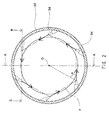
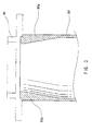
- FIG. 2 is a schematic cross sectional view of the discharge pipe 32 (except for the housing 30 which connects the discharge pipe 32 to the reaction tube 12). Further, FIG. 3 is a cross sectional view taken along line A-A of FIG. 2 and FIG. 4 is a cross sectional view taken along line B-B of FIG. 2 .
- the discharge pipe 32 is a tubular body coupled to the lower end of the reaction tube 12 via the housing 30 (see FIG. 3 ), and has an inner diameter which is substantially the same as that of the reaction tube 12.
- portions of the discharge pipe 32 near the upstream edge i.e. the edge portions on the side of the reaction tube 12
- the discharge pipe 32 is formed to have a slightly thicker wall thickness near the upstream edge than the downstream side.
- Such a structure in which the wall thickness near the upstream edge is thick facilitates stable support of the nozzle 34 as will be described below.
- a straight tubular body having a uniform wall thickness may be used or a seat by means of a boss and so on may be provided.
- a plurality of (six in the illustrated example) nozzles 34 are provided in a fixed manner on the side surface of the discharge pipe 32. These plural nozzles 34 function as a swirl flow generation unit which generates swirl flow within the discharge pipe 32.
- Each nozzle 34 is connected to a gas supply source (not shown) and emits gas into the discharge pipe 32 in accordance with an instruction from the controller.
- the type of this gas is not particularly limited as long as the gas does not deteriorate or alter the quality of the carbon nanotubes after synthesis. Accordingly, gas which is the same type as the carrier gas may be used, or nitrogen may be used. Further, the flow velocity (flow rate) of the gas emitted from each nozzle 34 should have a magnitude at which the carbon nanotubes can be transferred without being adhered.
- this nozzle 34 is fixed to the side wall of the discharge pipe 32 in a direction which is deflected with respect to the center O of the discharge pipe 32.
- the orientation directions of all the nozzles 34 are the same.
- the plural nozzles 34 are arranged at equal intervals in the circumferential direction.
- the nozzles 34 may be disposed, for example, in the directions which are substantially identical with sides of a regular polygon having apexes at positions where tips of the plurality of nozzles are located. More specifically, in the example illustrated in FIG. 2 , the nozzles 34 may be disposed such that each of sides of a regular hexagon, having apexes each corresponding to the tip of each nozzle 34, substantially corresponds to the orientation direction of each nozzle 34.
- each nozzle 34 is fixed while being directed diagonally downward.
- gas which is directed diagonally downward is emitted from each nozzle 34, and carbon nanotubes are actively transferred to the downstream side by the gas.
- the inclination angle of each nozzle can be adjusted as appropriate depending on the number of nozzles. While, when six nozzles are disposed as in the present embodiment, the inclination angle is preferably about 10 degrees, the inclination angle may be increased or decreased within a range of about ⁇ 10 degrees.
- each nozzle 34 in order to reduce the amount of carbon nanotubes adhered to the inner side surface of the discharge pipe 32, it is desirable to provide each nozzle 34 at a position as close to the upstream edge of the discharge pipe 32 as possible.
- the upstream edge of the discharge pipe 32 which is connected with the reaction tube 12 which is kept at a high temperature, is likely to have a relatively high temperature. More specifically, as illustrated in FIG. 1 , in the section near the upstream edge of the discharge pipe 32, the second middle temperature region Ec having substantially the same temperature as that in the section near the downstream edge of the reaction tube 12 is formed.
- this second middle temperature region Ec does not have a temperature which is as high as the temperature of the reaction region Eb in which synthesis reaction of carbon nanotubes is performed, the second middle temperature region Ec can have a considerably high temperature state (several hundred degrees). There is therefore a possibility that the nozzle 34 will be damaged by heat in this second middle temperature region Ec. Accordingly, the nozzle 34 is provided near the upstream edge of the low temperature region Ed having a temperature which is equal to or lower than the allowable temperature of the nozzle 34.
- a swirl flow in a vortex or spiral shape is formed within the discharge pipe 32, which flows along the inner side surface towards the downstream side (see FIG. 2 ).
- the carbon nanotubes passing through the discharge pipe 32 are isolated from the wall surface and converged near the center of the discharge pipe 32.
- the carbon nanotubes are prevented from moving to the inner side surface of the discharge pipe 32, so that adhesion of the carbon nanotubes to the inner side surface is prevented.
- the present embodiment it is possible to effectively prevent adhesion of carbon nanotubes to the inner side surface of the discharge pipe 32, so that the production efficiency of the carbon nanotubes can be significantly increased.
- the discharge pipe 32 and the reaction tube 12 are separate members in the above example, these members may be formed integrally.
- the nozzles 34 may be disposed at different heights.
Landscapes
- Chemical & Material Sciences (AREA)
- Engineering & Computer Science (AREA)
- Nanotechnology (AREA)
- Organic Chemistry (AREA)
- Crystallography & Structural Chemistry (AREA)
- Materials Engineering (AREA)
- Chemical Kinetics & Catalysis (AREA)
- Manufacturing & Machinery (AREA)
- General Physics & Mathematics (AREA)
- Physics & Mathematics (AREA)
- Condensed Matter Physics & Semiconductors (AREA)
- Inorganic Chemistry (AREA)
- Composite Materials (AREA)
- Carbon And Carbon Compounds (AREA)
Abstract
Description
- The present invention relates to a carbon nanotube synthesis process apparatus for producing carbon nanotubes such as carbon nanotubes and carbon fibers by using a gas-phase flow method.
- Carbon nanotubes are crystalline carbon having a structure in which a thin layer of graphite crystal is rolled up to form a cylindrical shape. More specifically, carbon atoms forming carbon nanotubes form a graphene sheet having a flat or curved surface formed of six-membered rings of carbon molecules arranged in a hexagonal pattern, and the graphene sheet is rolled up to form a cylindrical carbon nanotube. In general, the diameter of carbon nanotubes is 0.4 nm to tens of nm, and the length of carbon nanotubes is normally several tens to several thousands or more times as long as the diameter thereof.
- Such carbon nanotubes have a high degree of strength, excellent electrical conductivity, thermal conductivity, and lubrication property, and have therefore drawn attentions from various application aspects. Further, in order to allow carbon nanotubes to be distributed at lower costs, more efficient technologies for producing carbon nanotubes are being required.
- A so-called gas-phase flow method has been known as one of technologies for producing carbon nanotubes. With this gas-phase flow method, carbon-containing materials and a catalyst metal are caused to flow along with carrier gas within a high-temperature furnace to thereby thermally decompose and synthesize materials such as carbon sources in the gas-phase, thereby producing carbon nanotubes. As this gas-phase flow method is suitable for mass production, there have been proposed a large number of improved technologies/processes for this method.
- With this gas-phase flow method, there are cases in which a discharge pipe disposed downstream of a reaction tube is clogged with produced carbon nanotubes. Specifically, while carbon nanotubes synthesized in the reaction tube are supposed to flow in the downstream direction and to be finally discharged externally through the discharge pipe provided downstream of the reaction tube, there are cases in which, during this transfer process, the carbon nanotubes adhere to the inner surface of the discharge pipe. Once even a little amount of nanotubes is adhered to the inner surface of the discharge pipe, further carbon nanotubes are easily adhered to (or easily caught by) the carbon nanotubes already adhered to the inner surface, resulting in a rapid increase in the amount of carbon nanotubes accumulated in the discharge pipe. This may then finally result in clogging of the discharge pipe with the carbon nanotubes. In order to deal with this problem, conventionally, operation of the production apparatus is periodically interrupted and remove the carbon nanotubes adhered to the inner surface of the discharge pipe. However, the operations of periodical interruption of a production apparatus and removal of the carbon nanotubes as described above have caused problems including a reduction in the production efficiency of carbon nanotubes and an increase in the burden on operators.
-
JP 2001-73231 A JP 2001-115342 A - Accordingly, the present invention aims at providing a carbon nanotube synthesis process apparatus with which the production efficiency of carbon nanotubes can be increased.
- In accordance with an aspect of the present invention, there is provided a carbon nanotube synthesis process apparatus for producing a carbon nanotube by using a gas-phase method, the apparatus including a reaction tube; a supply unit which supplies a carbon-containing raw material from an upstream side of the reaction tube; a heating unit which heats the reaction tube to thereby generate within the reaction tube a reaction field which thermally decomposes the carbon-containing raw material to produce a carbon nanotube; a discharge pipe disposed downstream of the reaction tube for directing the carbon nanotube produced in the reaction tube to the outside; and a swirl flow generation unit which generates a swirl flow flowing from an inner side surface of the discharge pipe along the inner side surface thereof.
- In accordance with another preferable embodiment, the swirl flow generation unit includes a plurality of nozzles disposed on the inner side surface of the discharge pipe for discharging gases in a direction which is deflected from the center of the discharge pipe. Preferably, the plurality of nozzles are arranged at equal intervals in the circumferential direction of the discharge pipe. Further, the nozzles are preferably disposed near an upstream end of a low-temperature region of the discharge pipe having a temperature lower than the allowable temperature of the nozzles.
- According to the present invention, a swirl flow flowing from the inner side surface of the discharge pipe along the inner side surface thereof is generated within the discharge pipe. With this swirl flow, as the carbon nanotubes are isolated from the wall surface and transferred toward the center of the discharge pipe, adhesion of the carbon nanotubes to the inner side surface and resulting clogging of the discharge pipe can be effectively prevented. Also, even if the carbon nanotubes are adhered to the inner side surface, the carbon nanotubes are removed by the swirl flow. Consequently, continuous operation of the carbon nanotube synthesis process apparatus can be achieved so that the production efficiency thereof can be increased.
- These and other objects of the invention will be explained in the description below, in connection with the accompanying drawings, in which:
-
FIG. 1 is a view schematically illustrating a structure of a carbon nanotube synthesis process apparatus according to an embodiment of the present invention; -
FIG. 2 is a schematic cross sectional view of a discharge pipe; -
FIG. 3 is a cross sectional view taken along line A-A inFIG. 2 ; and -
FIG. 4 is a cross sectional view taken along line B-B inFIG. 2 . - 10 carbon nanotube synthesis process apparatus, 12 reaction tube, 14 heating device, 18 raw material supply mechanism, 20 raw material tank, 22 pump, 24 raw material supply line, 26 supply nozzle, 28 introduction tube, 30 housing, 32 discharge pipe, 34 nozzle.
- A preferred embodiment of the present invention will be described with reference to the drawings.
FIG. 1 is a view schematically illustrating a structure of a carbon nanotubesynthesis process apparatus 10 according to an embodiment of the present invention. The carbon nanotube synthesis process apparatus is an apparatus for producing carbon nanotubes by a gas-phase flow method, and includes areaction tube 12, aheating device 14 for heating thereaction tube 12, a rawmaterial supply mechanism 18 for supplying a raw material liquid to thereaction tube 12, adischarge pipe 32 for guiding the carbon nanotubes produced in thereaction tube 12 to a collection tank (not shown), and so on. - The
reaction tube 12 is a tubular member which is heated by theheating device 14 which will be described below to generate therein a reaction field which enables synthesis reaction of carbon nanotubes. According to the present embodiment, a so-called vertical downward flowtype reaction tube 12, which is designed such that the synthesis reaction of the carbon nanotubes progresses from the upper portion toward the lower portion of thereaction tube 12, is used. However, a vertical upward flow type reaction tube in which the synthesis reaction progresses from the lower portion toward the upper portion, and a lateral type reaction tube in which the synthesis reaction progresses in the lateral direction may also be used as long as the stable reaction field can be provided. Further, while it is desirable for thereaction tube 12 to be of a substantially cylinder shape, thereaction tube 12 may be of a rectangular column shape as long as the stable reaction field can be provided. - The
heating device 14 is provided around the outer peripheral surface of thereaction tube 12. Theheating device 14 is formed of an electric furnace, for example, and is designed to heat the interior of thereaction tube 12 to a temperature at which carbon nanotubes can be synthesized (hereinafter referred to as a "synthesis temperature"). - The
heating device 14 is disposed so that theheating device 14 can heat the interior of thereaction tube 12 as uniformly as possible. However, it is normal for, at edge portions of thereaction tube 12, the area of heat loss to be larger than that in the center portion of thereaction tube 12, and the temperature thereof tends to be low. In other words, in the interior of thereaction tube 12, the temperature distribution is generated in which the temperatures are lowered towards both ends of thereaction tube 12. Although it is not possible to clearly define the boundaries in this temperature distribution, a first middle temperature region Ea below the synthesis temperature is formed near the upstream edge of thereaction tube 12 and a second middle temperature region Ec below the synthesis temperature is formed near the downstream edge of thereaction tube 12. Further, in the center portion of thereaction tube 12, i.e. between the first middle temperature region Ea and the second middle temperature region Ec, a reaction region Eb in which the temperature reaches the synthesis temperature at which carbon nanotubes can be synthesized is formed. Here, while in the present embodiment theheating device 14 is provided only around the outer periphery of thereaction tube 12, theheating device 14 may additionally be provided in the interior of thereaction tube 12 in accordance with the inner diameter of thereaction tube 12 and the performances of eachheating device 14. - A raw material liquid is supplied to the
reaction tube 12 by the rawmaterial supply mechanism 18. The rawmaterial supply mechanism 18 includes araw material tank 20, asupply nozzle 26, a rawmaterial supply line 24, apump 22, and so on. Theraw material tank 20 is a container storing a raw material liquid. The raw material liquid is a carbon-containing liquid or a liquid in which an organic metal catalyst, inverse micelle particles containing an organic metal catalyst, a catalyst auxiliary, and so on are mixed. The raw material liquid is delivered through the rawmaterial supply line 24 to a plurality ofsupply nozzles 26. Delivery of the raw material liquid is performed by thepump 22 whose driving is controlled by a control section (not shown). - The
supply nozzle 26 is a nozzle which atomizes and supplies the raw material liquid, that has been delivered from theraw material tank 20, to thereaction tube 12. Thesupply nozzle 26 is disposed at the upstream edge of thereaction tube 12 such that the leading end thereof extends from the upstream edge surface of thereaction tube 12 into the interior of thereaction tube 12 so as to reach the reaction region Eb. WhileFIG. 1 illustrates an example in which twosupply nozzles 26 are provided, the number of thesupply nozzles 26 is not particularly limited and may be one or three or more. - When the atomized raw material liquid supplied from the
supply nozzle 26 is supplied to thereaction tube 12 having a high temperature, a carbon source, an organic metal catalyst, and a catalyst auxiliary contained in the raw material liquid are evaporated. Then, due to thermal decomposition of the organic metal catalyst, catalyst fine particles are produced. When the carbon sources come in contact with the catalyst fine particles thus produced, a carbon hexagonal plane is formed on the surface of the catalyst fine particles to thereby form a cylindrical graphene sheet. Further, when this graphene sheet gradually grows in the longitudinal direction in the process in which the catalyst fine particles descend within thereaction tube 12, carbon nanotubes are produced. - An
introduction tube 28 for carrier gas is provided around thesupply nozzle 26. Theintroduction tube 28 is connected to a gas supply source through the gas supply line. The carrier gas does not affect the synthesis reaction of carbon nanotubes and transfers the raw material and the carbon nanotube being produced toward the downstream side. - The supply method of the raw material and the carrier gas described above is only an example and may be modified as desired as long as carbon nanotubes can be produced by a gas-phase flow method in which a synthesis reaction of the raw material is caused in the gas-phase. For example, the raw material may be supplied in a gas state, rather than a liquid state (the raw material liquid). Also, the
introduction tube 28 many be provided not only around thesupply nozzle 26 but also near the inner peripheral edge of thereaction tube 12 so that the carrier gas can flow from theintroduction tube 28 along the inner side surface ofreaction tube 12. With this structure, adhesion of the carbon nanotubes onto the inner side surface of thereaction tube 12 can be prevented. - A
discharge pipe 32 is connected with the downstream edge of thereaction tube 12. Thedischarge pipe 32 is a tubular body which externally guides the carbon nanotubes produced in thereaction tube 12 and is coupled to the downstream edge of thereaction tube 12 via ahousing 30. A collection tank is provided under thedischarge pipe 32 to collect the carbon nanotubes which are produced. - Conventionally, clogging of the
discharge pipe 32 with carbon nanotubes tends to occur. More specifically, while the carbon nanotubes flowing to thedischarge pipe 32 should pass through thedischarge pipe 32 and be discharged out to the collection tank, some carbon nanotubes adhere to the inner surface side of thedischarge pipe 32 and stay thereon. When there are any carbon nanatubes adhered to the inner side surface of thedischarge pipe 32, further carbon nanotubes are easily adhered to these carbon nanotubes. Still further carbon nanotubes in turn adhere to the carbon nanotubes which are already adhered. Finally, a large amount of carbon nanotubes engage with each other and stay on the inner side surface of thedischarge pipe 32, which may result in clogging of the interior of thedischarge pipe 32 with the carbon nanotubes. - Such clogging caused by carbon nanotubes may have similarly occurred in the
reaction tube 12. Concerning prevention of clogging of thereaction tube 12, however, a large number of improved technologies have been conventionally proposed (for example,JP 2001-73231 A JP 20011-115342 A reaction tube 12 can be prevented to a certain degree by using these technologies. - On the other hand, no effective improved technologies have conventionally been proposed concerning clogging of the
discharge pipe 32. Further, as is clear fromFIG. 1 , thedischarge pipe 32 is not heated by theheating device 14. Empirical data shows that, when comparing high temperature portions and low temperature portions, carbon nanotubes are likely to adhere to low temperature portions. In other words, thedischarge pipe 32 is more likely to be clogged with carbon nanotubes than thereaction tube 12. It is a matter of fact that such clogging of thedischarge pipe 32, which inhibits discharge of the carbon nanotubes to the collection tank, is not desirable. In order to deal with this problem, it was conventionally necessary to periodically interrupt operation of the carbon nanotubesynthesis process apparatus 10 to remove the carbon nanotubes adhered to the inner side surface of thedischarge pipe 32 so as to prevent clogging of thedischarge pipe 32. These periodical operations for interrupting theproduction apparatus 10 and for removing carbon nanotubes cause a reduction in the production efficiency of the carbon nanotubes and an increase in the burden on operators. - Therefore, according to the present embodiment, in order to prevent clogging of the
discharge pipe 32 with carbon nanotubes, thedischarge pipe 32 is configured to have a special structure, as will be described in detail below. -
FIG. 2 is a schematic cross sectional view of the discharge pipe 32 (except for thehousing 30 which connects thedischarge pipe 32 to the reaction tube 12). Further,FIG. 3 is a cross sectional view taken along line A-A ofFIG. 2 andFIG. 4 is a cross sectional view taken along line B-B ofFIG. 2 . - The
discharge pipe 32 according to the present embodiment is a tubular body coupled to the lower end of thereaction tube 12 via the housing 30 (seeFIG. 3 ), and has an inner diameter which is substantially the same as that of thereaction tube 12. However, portions of thedischarge pipe 32 near the upstream edge (i.e. the edge portions on the side of the reaction tube 12) are formed to have a slightly taperedportion 32a in which the inner diameter thereof is gradually reduced toward the upstream edge, as illustrated inFIG. 3 . Stated in a different manner, thedischarge pipe 32 is formed to have a slightly thicker wall thickness near the upstream edge than the downstream side. Such a structure in which the wall thickness near the upstream edge is thick facilitates stable support of thenozzle 34 as will be described below. However, as long as stable support for thenozzle 34 can be secured, it is not always necessary to provide the thicker wall portion (taper portion), and a straight tubular body having a uniform wall thickness may be used or a seat by means of a boss and so on may be provided. - A plurality of (six in the illustrated example)
nozzles 34 are provided in a fixed manner on the side surface of thedischarge pipe 32. Theseplural nozzles 34 function as a swirl flow generation unit which generates swirl flow within thedischarge pipe 32. Eachnozzle 34 is connected to a gas supply source (not shown) and emits gas into thedischarge pipe 32 in accordance with an instruction from the controller. The type of this gas is not particularly limited as long as the gas does not deteriorate or alter the quality of the carbon nanotubes after synthesis. Accordingly, gas which is the same type as the carrier gas may be used, or nitrogen may be used. Further, the flow velocity (flow rate) of the gas emitted from eachnozzle 34 should have a magnitude at which the carbon nanotubes can be transferred without being adhered. - As illustrated in
FIG. 2 , thisnozzle 34 is fixed to the side wall of thedischarge pipe 32 in a direction which is deflected with respect to the center O of thedischarge pipe 32. In this case, the orientation directions of all thenozzles 34 are the same. Also, theplural nozzles 34 are arranged at equal intervals in the circumferential direction. Here, while the deflection angle α of eachnozzle 34 with respect to the diameter can be adjusted as appropriate depending on the flow velocity of the gas to be emitted and the number ofnozzles 34, thenozzles 34 may be disposed, for example, in the directions which are substantially identical with sides of a regular polygon having apexes at positions where tips of the plurality of nozzles are located. More specifically, in the example illustrated inFIG. 2 , thenozzles 34 may be disposed such that each of sides of a regular hexagon, having apexes each corresponding to the tip of eachnozzle 34, substantially corresponds to the orientation direction of eachnozzle 34. - Further, as illustrated in
FIG. 4 , eachnozzle 34 is fixed while being directed diagonally downward. With this arrangement, gas which is directed diagonally downward is emitted from eachnozzle 34, and carbon nanotubes are actively transferred to the downstream side by the gas. Here, the inclination angle of each nozzle can be adjusted as appropriate depending on the number of nozzles. While, when six nozzles are disposed as in the present embodiment, the inclination angle is preferably about 10 degrees, the inclination angle may be increased or decreased within a range of about ±10 degrees. - Here, in order to reduce the amount of carbon nanotubes adhered to the inner side surface of the
discharge pipe 32, it is desirable to provide eachnozzle 34 at a position as close to the upstream edge of thedischarge pipe 32 as possible. However, the upstream edge of thedischarge pipe 32, which is connected with thereaction tube 12 which is kept at a high temperature, is likely to have a relatively high temperature. More specifically, as illustrated inFIG. 1 , in the section near the upstream edge of thedischarge pipe 32, the second middle temperature region Ec having substantially the same temperature as that in the section near the downstream edge of thereaction tube 12 is formed. While this second middle temperature region Ec does not have a temperature which is as high as the temperature of the reaction region Eb in which synthesis reaction of carbon nanotubes is performed, the second middle temperature region Ec can have a considerably high temperature state (several hundred degrees). There is therefore a possibility that thenozzle 34 will be damaged by heat in this second middle temperature region Ec. Accordingly, thenozzle 34 is provided near the upstream edge of the low temperature region Ed having a temperature which is equal to or lower than the allowable temperature of thenozzle 34. - When the gas is emitted from a plurality of
nozzles 34 disposed as described above, a swirl flow in a vortex or spiral shape is formed within thedischarge pipe 32, which flows along the inner side surface towards the downstream side (seeFIG. 2 ). With this swirl flow, the carbon nanotubes passing through thedischarge pipe 32 are isolated from the wall surface and converged near the center of thedischarge pipe 32. In other words, the carbon nanotubes are prevented from moving to the inner side surface of thedischarge pipe 32, so that adhesion of the carbon nanotubes to the inner side surface is prevented. As a result, the need for periodical interrupting operation of theproduction device 10 and for removing the carbon nanotubes adhered to the inner surface side can be eliminated, so that long-time continuous operation of theproduction device 10 can be achieved. Consequently, the production efficiency of carbon nanotubes can be significantly increased. - As described above, according to the present embodiment, it is possible to effectively prevent adhesion of carbon nanotubes to the inner side surface of the
discharge pipe 32, so that the production efficiency of the carbon nanotubes can be significantly increased. It should be noted that while thedischarge pipe 32 and thereaction tube 12 are separate members in the above example, these members may be formed integrally. Further, while in the above example all of the plurality ofnozzles 34 are disposed at the same height, thenozzles 34 may be disposed at different heights.
Claims (4)
- A carbon nanotube synthesis process apparatus for producing a carbon nanotube by using a gas-phase method, the apparatus comprising:a reaction tube;a supply unit which supplies a carbon-containing raw material from an upstream side of the reaction tube;a heating unit which heats the reaction tube to thereby generate within the reaction tube a reaction field which thermally decomposes the carbon-containing raw material to produce a carbon nanotube;a discharge pipe disposed on a downstream side of the reaction tube for directing the carbon nanotube produced within the reaction tube to outside; anda swirl flow generation unit which generates a swirl flow flowing from an inner side surface of the discharge pipe along the inner side surface thereof.
- The carbon nanotube synthesis process apparatus according to Claim 1, wherein
the swirl flow generation unit includes a plurality of nozzles disposed on an inner side surface of the discharge pipe for emitting gas in a direction which is deflected from the center of the discharge pipe. - The carbon nanotube synthesis process apparatus according to Claim 2, wherein
the plurality of nozzles are arranged at equal intervals in a circumferential direction of the discharge pipe. - The carbon nanotube synthesis process apparatus according to Claim 2, wherein
the nozzles are disposed near an upstream edge of a low-temperature region of the discharge pipe having a temperature which is lower than an allowable temperature of the nozzles.
Applications Claiming Priority (2)
| Application Number | Priority Date | Filing Date | Title |
|---|---|---|---|
| JP2008010397 | 2008-01-21 | ||
| PCT/JP2008/070590 WO2009093370A1 (en) | 2008-01-21 | 2008-11-12 | Apparatus for producing carbon nanotube |
Publications (2)
| Publication Number | Publication Date |
|---|---|
| EP2236460A1 true EP2236460A1 (en) | 2010-10-06 |
| EP2236460A4 EP2236460A4 (en) | 2012-01-11 |
Family
ID=40900886
Family Applications (1)
| Application Number | Title | Priority Date | Filing Date |
|---|---|---|---|
| EP08871384A Withdrawn EP2236460A4 (en) | 2008-01-21 | 2008-11-12 | APPARATUS FOR PRODUCING CARBON NANOTUBE |
Country Status (10)
| Country | Link |
|---|---|
| US (1) | US8557190B2 (en) |
| EP (1) | EP2236460A4 (en) |
| JP (1) | JP5282043B2 (en) |
| KR (1) | KR20100108599A (en) |
| CN (1) | CN101910061B (en) |
| CA (1) | CA2711378A1 (en) |
| IL (1) | IL206717A0 (en) |
| RU (1) | RU2010133891A (en) |
| TW (1) | TW200932667A (en) |
| WO (1) | WO2009093370A1 (en) |
Cited By (1)
| Publication number | Priority date | Publication date | Assignee | Title |
|---|---|---|---|---|
| CN110291038A (en) * | 2017-02-13 | 2019-09-27 | 崇实大学校产学协力团 | Carbon nanotube aggregate preparation device |
Families Citing this family (20)
| Publication number | Priority date | Publication date | Assignee | Title |
|---|---|---|---|---|
| US9061913B2 (en) | 2007-06-15 | 2015-06-23 | Nanocomp Technologies, Inc. | Injector apparatus and methods for production of nanostructures |
| JP5735234B2 (en) * | 2010-08-26 | 2015-06-17 | 帝人株式会社 | Method and apparatus for producing carbon nanotube continuous fiber |
| EP2736844A4 (en) * | 2011-07-28 | 2015-08-26 | Nanocomp Technologies Inc | Systems and methods for nanoscopically aligned carbon nanotubes |
| KR101587685B1 (en) * | 2013-03-29 | 2016-01-21 | 주식회사 엘지화학 | Fluidized bed reactor and preparatio of carbon nanostructures using same |
| JP6404916B2 (en) | 2013-06-17 | 2018-10-17 | ナノコンプ テクノロジーズ インコーポレイテッド | Stripping and dispersing agents for nanotubes, bundles and fibers |
| CN104641028B (en) * | 2013-06-18 | 2016-08-31 | Lg化学株式会社 | The device preparing carbon nano-tube fibre and the method utilizing described device to prepare carbon nano-tube fibre |
| KR101708333B1 (en) * | 2014-12-02 | 2017-02-21 | 한국에너지기술연구원 | MANUFACTURING DEVICE OF Si NANOPARTICLES USING MICROWAVE PLASMA AND MANUFACTURING METHOD USING THE SAME |
| WO2016126818A1 (en) | 2015-02-03 | 2016-08-11 | Nanocomp Technologies, Inc. | Carbon nanotube structures and methods for production thereof |
| CN106145089A (en) * | 2016-08-31 | 2016-11-23 | 无锡东恒新能源科技有限公司 | The synthesizer of batch production CNT |
| CN106395792B (en) * | 2016-08-31 | 2018-09-25 | 无锡东恒新能源科技有限公司 | Carbon nano-tube growth apparatus |
| CN106379887A (en) * | 2016-08-31 | 2017-02-08 | 无锡东恒新能源科技有限公司 | Carbon nanotube continuous generating device |
| CN106185874A (en) * | 2016-08-31 | 2016-12-07 | 无锡东恒新能源科技有限公司 | CNT continuous preparation device |
| CN107934943A (en) * | 2017-12-25 | 2018-04-20 | 深圳市山木新能源科技股份有限公司 | A kind of graphene powder manufacturing equipment |
| JP7455805B2 (en) * | 2019-02-22 | 2024-03-26 | 住友電気工業株式会社 | Carbon nanotube production method, carbon nanotube assembly wire production method, carbon nanotube assembly wire bundle production method, carbon nanotube production apparatus, carbon nanotube assembly wire production apparatus, and carbon nanotube assembly wire bundle production apparatus |
| CN112974010A (en) * | 2019-12-13 | 2021-06-18 | 南京源昌新材料有限公司 | Special atomizing device for atomizing carbon nanotube raw materials |
| KR102867651B1 (en) | 2020-08-26 | 2025-10-10 | 주식회사 엘지화학 | Distributor for fluidized bed reactor and fluidized bed reactor comprising the same |
| WO2022124867A1 (en) | 2020-12-11 | 2022-06-16 | 주식회사 엘지화학 | Carbon nanotube manufacturing apparatus and manufacturing method |
| KR20220083598A (en) | 2020-12-11 | 2022-06-20 | 주식회사 엘지화학 | Carbon nanotube manufacturing device |
| US12098074B1 (en) | 2021-05-20 | 2024-09-24 | University Of Maryland, College Park | Systems and methods of making carbon nanotubes |
| USD1080852S1 (en) | 2023-06-20 | 2025-06-24 | Nippon Electrode Co., Ltd. | Heat-resistant tube for vertical heat treatment equipment |
Family Cites Families (20)
| Publication number | Priority date | Publication date | Assignee | Title |
|---|---|---|---|---|
| US4106892A (en) * | 1975-12-04 | 1978-08-15 | Kureha Kagaku Kogyo Kabushiki Kaisha | Apparatus for heat treatment using downwardly swirling hot gas flow |
| EP0028086A1 (en) * | 1979-10-29 | 1981-05-06 | Sykes Construction Services Limited | Material transporting apparatus |
| JPH01207419A (en) * | 1988-02-10 | 1989-08-21 | Nkk Corp | Manufacturing method of vapor grown carbon fiber |
| JPH10314963A (en) * | 1997-05-22 | 1998-12-02 | Daido Steel Co Ltd | Gas shield method and gas shield device |
| JPH11107052A (en) * | 1997-09-30 | 1999-04-20 | Nikkiso Co Ltd | Vapor-grown carbon fiber continuous production apparatus and vapor-grown carbon fiber continuous production method |
| JP4065616B2 (en) * | 1998-12-11 | 2008-03-26 | 日機装株式会社 | Vapor growth carbon fiber production equipment |
| US6878360B1 (en) * | 1999-09-01 | 2005-04-12 | Nikkiso Company Limited | Carbon fibrous matter, production device of carbon fibrous matter, production method of carbon fibrous matter and deposit prevention device for carbon fibrous matter |
| JP4177533B2 (en) | 1999-10-08 | 2008-11-05 | 日機装株式会社 | Fine vapor growth carbon fiber production apparatus, fine vapor growth carbon fiber production method, fine vapor growth carbon fiber adhesion prevention apparatus, and fine vapor growth carbon fiber |
| JP4115637B2 (en) | 1999-09-01 | 2008-07-09 | 日機装株式会社 | Carbon fiber material manufacturing apparatus, carbon fiber material manufacturing method, and carbon fiber material adhesion preventing apparatus |
| JP4000258B2 (en) * | 2000-12-28 | 2007-10-31 | 日機装株式会社 | Method for producing vapor grown carbon fiber |
| EP1445236A1 (en) | 2003-02-05 | 2004-08-11 | Université de Liège | Method and apparatus for producing carbon nanotubes |
| CN100381356C (en) | 2003-06-10 | 2008-04-16 | 先锋奈米碳素株式会社 | How to make fullerenes |
| JP3861075B2 (en) | 2003-06-17 | 2006-12-20 | フロンティアカーボン株式会社 | Fullerene production method and equipment |
| US20050129607A1 (en) * | 2003-12-16 | 2005-06-16 | Hiroaki Takehara | Method for producing fullerenes |
| JP2005179122A (en) * | 2003-12-19 | 2005-07-07 | Frontier Carbon Corp | Conveying method and conveying device for fullerene-containing soot |
| US20050163696A1 (en) * | 2004-01-28 | 2005-07-28 | Uhm Han S. | Synthesis of carbon nanotubes by making use of microwave plasma torch |
| US7485600B2 (en) * | 2004-11-17 | 2009-02-03 | Honda Motor Co., Ltd. | Catalyst for synthesis of carbon single-walled nanotubes |
| TWI374857B (en) | 2004-12-13 | 2012-10-21 | Nikkiso Co Ltd | Method for manufacturing single-walled carbon nanotube |
| JP2006198463A (en) * | 2005-01-18 | 2006-08-03 | Jfe Steel Kk | Gas cooling device for depositing solids |
| JP2006315889A (en) * | 2005-05-11 | 2006-11-24 | Bussan Nanotech Research Institute Inc | Removal method of carbonaceous scale |
-
2008
- 2008-11-12 KR KR1020107018499A patent/KR20100108599A/en not_active Withdrawn
- 2008-11-12 CA CA2711378A patent/CA2711378A1/en not_active Abandoned
- 2008-11-12 EP EP08871384A patent/EP2236460A4/en not_active Withdrawn
- 2008-11-12 JP JP2009550425A patent/JP5282043B2/en not_active Expired - Fee Related
- 2008-11-12 RU RU2010133891/05A patent/RU2010133891A/en unknown
- 2008-11-12 WO PCT/JP2008/070590 patent/WO2009093370A1/en not_active Ceased
- 2008-11-12 CN CN2008801253293A patent/CN101910061B/en not_active Expired - Fee Related
- 2008-11-12 US US12/863,528 patent/US8557190B2/en not_active Expired - Fee Related
- 2008-12-19 TW TW097149633A patent/TW200932667A/en unknown
-
2010
- 2010-06-30 IL IL206717A patent/IL206717A0/en unknown
Cited By (2)
| Publication number | Priority date | Publication date | Assignee | Title |
|---|---|---|---|---|
| CN110291038A (en) * | 2017-02-13 | 2019-09-27 | 崇实大学校产学协力团 | Carbon nanotube aggregate preparation device |
| EP3572376A4 (en) * | 2017-02-13 | 2020-10-07 | Foundation of Soongsil University-Industry Cooperation | DEVICE FOR PRODUCING A CARBON NANOTUBE AGGREGATE |
Also Published As
| Publication number | Publication date |
|---|---|
| US8557190B2 (en) | 2013-10-15 |
| KR20100108599A (en) | 2010-10-07 |
| RU2010133891A (en) | 2012-02-27 |
| US20100296983A1 (en) | 2010-11-25 |
| JP5282043B2 (en) | 2013-09-04 |
| CA2711378A1 (en) | 2009-07-30 |
| CN101910061B (en) | 2013-08-28 |
| IL206717A0 (en) | 2010-12-30 |
| WO2009093370A1 (en) | 2009-07-30 |
| CN101910061A (en) | 2010-12-08 |
| JPWO2009093370A1 (en) | 2011-05-26 |
| EP2236460A4 (en) | 2012-01-11 |
| TW200932667A (en) | 2009-08-01 |
Similar Documents
| Publication | Publication Date | Title |
|---|---|---|
| US8557190B2 (en) | Carbon nanotube synthesis process apparatus | |
| US6878360B1 (en) | Carbon fibrous matter, production device of carbon fibrous matter, production method of carbon fibrous matter and deposit prevention device for carbon fibrous matter | |
| US10930473B2 (en) | Apparatus and method for plasma synthesis of carbon nanotubes | |
| JP4968643B2 (en) | Method for producing single-walled carbon nanotube | |
| US20160030910A1 (en) | High-throughput particle production using a plasma system | |
| CN105284193B (en) | Produced using the high yield particle of plasma system | |
| US8834827B2 (en) | Method and apparatus for the continuous production and functionalization of single-walled carbon nanotubes using a high frequency plasma torch | |
| KR20220147591A (en) | Method for producing carbon nanotube aggregates | |
| EP1340242B1 (en) | Arc electrodes for synthesis of carbon nanostructures | |
| JP3810394B2 (en) | Reaction tube equipment with internal heating element | |
| CN1520473A (en) | Method and apparatus for producing vapor-grown carbon fibers | |
| JP7503146B2 (en) | CNT filament formation by buoyancy-induced elongational flow | |
| HK1147085A (en) | Apparatus for producing carbon nanotube | |
| JP4394981B2 (en) | Raw material gas supply nozzle, carbon nanofiber manufacturing apparatus, and carbon nanofiber manufacturing method | |
| JP2001073231A (en) | Apparatus for manufacturing carbon fiber material, method for manufacturing carbon fiber material, and apparatus for preventing carbon fiber material adhesion | |
| JPH11107052A (en) | Vapor-grown carbon fiber continuous production apparatus and vapor-grown carbon fiber continuous production method | |
| JP4392283B2 (en) | Carbon nanofiber manufacturing method and carbon nanofiber post-processing method | |
| JP2005060196A (en) | Equipment and method for manufacturing fullerene | |
| JPH0978360A (en) | Method for producing vapor grown carbon fiber | |
| JP4987822B2 (en) | Nanocarbon generation furnace | |
| JP4152777B2 (en) | Raw material gas supply nozzle device | |
| JP2003213531A (en) | Method for producing vapor grown carbon fiber and apparatus for producing vapor grown carbon fiber | |
| JP2004027452A (en) | Method for producing vapor-phase carbon fiber and apparatus therefor | |
| JP2004224636A (en) | Continuous production machine for carbon nanotube, carbon nanohorn and carbon nanomaterial | |
| JP2002088591A (en) | Method for producing fine carbon fiber |
Legal Events
| Date | Code | Title | Description |
|---|---|---|---|
| PUAI | Public reference made under article 153(3) epc to a published international application that has entered the european phase |
Free format text: ORIGINAL CODE: 0009012 |
|
| 17P | Request for examination filed |
Effective date: 20100702 |
|
| AK | Designated contracting states |
Kind code of ref document: A1 Designated state(s): AT BE BG CH CY CZ DE DK EE ES FI FR GB GR HR HU IE IS IT LI LT LU LV MC MT NL NO PL PT RO SE SI SK TR |
|
| AX | Request for extension of the european patent |
Extension state: AL BA MK RS |
|
| DAX | Request for extension of the european patent (deleted) | ||
| REG | Reference to a national code |
Ref country code: HK Ref legal event code: DE Ref document number: 1147085 Country of ref document: HK |
|
| A4 | Supplementary search report drawn up and despatched |
Effective date: 20111209 |
|
| RIC1 | Information provided on ipc code assigned before grant |
Ipc: C01B 31/02 20060101AFI20111205BHEP |
|
| 17Q | First examination report despatched |
Effective date: 20130318 |
|
| REG | Reference to a national code |
Ref country code: HK Ref legal event code: WD Ref document number: 1147085 Country of ref document: HK |
|
| STAA | Information on the status of an ep patent application or granted ep patent |
Free format text: STATUS: THE APPLICATION HAS BEEN WITHDRAWN |
|
| 18W | Application withdrawn |
Effective date: 20170907 |