EP2236433A1 - Container - Google Patents
Container Download PDFInfo
- Publication number
- EP2236433A1 EP2236433A1 EP10157026A EP10157026A EP2236433A1 EP 2236433 A1 EP2236433 A1 EP 2236433A1 EP 10157026 A EP10157026 A EP 10157026A EP 10157026 A EP10157026 A EP 10157026A EP 2236433 A1 EP2236433 A1 EP 2236433A1
- Authority
- EP
- European Patent Office
- Prior art keywords
- outer sheath
- container according
- container
- central wall
- attachable
- Prior art date
- Legal status (The legal status is an assumption and is not a legal conclusion. Google has not performed a legal analysis and makes no representation as to the accuracy of the status listed.)
- Granted
Links
Images

Classifications
-
- B—PERFORMING OPERATIONS; TRANSPORTING
- B65—CONVEYING; PACKING; STORING; HANDLING THIN OR FILAMENTARY MATERIAL
- B65D—CONTAINERS FOR STORAGE OR TRANSPORT OF ARTICLES OR MATERIALS, e.g. BAGS, BARRELS, BOTTLES, BOXES, CANS, CARTONS, CRATES, DRUMS, JARS, TANKS, HOPPERS, FORWARDING CONTAINERS; ACCESSORIES, CLOSURES, OR FITTINGS THEREFOR; PACKAGING ELEMENTS; PACKAGES
- B65D43/00—Lids or covers for rigid or semi-rigid containers
- B65D43/02—Removable lids or covers
- B65D43/0202—Removable lids or covers without integral tamper element
- B65D43/0204—Removable lids or covers without integral tamper element secured by snapping over beads or projections
- B65D43/0212—Removable lids or covers without integral tamper element secured by snapping over beads or projections only on the outside, or a part turned to the outside, of the mouth
-
- B—PERFORMING OPERATIONS; TRANSPORTING
- B65—CONVEYING; PACKING; STORING; HANDLING THIN OR FILAMENTARY MATERIAL
- B65D—CONTAINERS FOR STORAGE OR TRANSPORT OF ARTICLES OR MATERIALS, e.g. BAGS, BARRELS, BOTTLES, BOXES, CANS, CARTONS, CRATES, DRUMS, JARS, TANKS, HOPPERS, FORWARDING CONTAINERS; ACCESSORIES, CLOSURES, OR FITTINGS THEREFOR; PACKAGING ELEMENTS; PACKAGES
- B65D15/00—Containers having bodies formed by interconnecting or uniting two or more rigid, or substantially rigid, sections made of different materials
- B65D15/02—Containers having bodies formed by interconnecting or uniting two or more rigid, or substantially rigid, sections made of different materials of curved, or partially curved, cross-section, e.g. cans, drums
- B65D15/16—Containers having bodies formed by interconnecting or uniting two or more rigid, or substantially rigid, sections made of different materials of curved, or partially curved, cross-section, e.g. cans, drums with curved, or partially curved, walls made of plastics material
- B65D15/18—Containers having bodies formed by interconnecting or uniting two or more rigid, or substantially rigid, sections made of different materials of curved, or partially curved, cross-section, e.g. cans, drums with curved, or partially curved, walls made of plastics material with end walls made of metal
-
- B—PERFORMING OPERATIONS; TRANSPORTING
- B65—CONVEYING; PACKING; STORING; HANDLING THIN OR FILAMENTARY MATERIAL
- B65D—CONTAINERS FOR STORAGE OR TRANSPORT OF ARTICLES OR MATERIALS, e.g. BAGS, BARRELS, BOTTLES, BOXES, CANS, CARTONS, CRATES, DRUMS, JARS, TANKS, HOPPERS, FORWARDING CONTAINERS; ACCESSORIES, CLOSURES, OR FITTINGS THEREFOR; PACKAGING ELEMENTS; PACKAGES
- B65D25/00—Details of other kinds or types of rigid or semi-rigid containers
- B65D25/34—Coverings or external coatings
-
- B—PERFORMING OPERATIONS; TRANSPORTING
- B65—CONVEYING; PACKING; STORING; HANDLING THIN OR FILAMENTARY MATERIAL
- B65D—CONTAINERS FOR STORAGE OR TRANSPORT OF ARTICLES OR MATERIALS, e.g. BAGS, BARRELS, BOTTLES, BOXES, CANS, CARTONS, CRATES, DRUMS, JARS, TANKS, HOPPERS, FORWARDING CONTAINERS; ACCESSORIES, CLOSURES, OR FITTINGS THEREFOR; PACKAGING ELEMENTS; PACKAGES
- B65D51/00—Closures not otherwise provided for
- B65D51/24—Closures not otherwise provided for combined or co-operating with auxiliary devices for non-closing purposes
- B65D51/28—Closures not otherwise provided for combined or co-operating with auxiliary devices for non-closing purposes with auxiliary containers for additional articles or materials
-
- B—PERFORMING OPERATIONS; TRANSPORTING
- B65—CONVEYING; PACKING; STORING; HANDLING THIN OR FILAMENTARY MATERIAL
- B65D—CONTAINERS FOR STORAGE OR TRANSPORT OF ARTICLES OR MATERIALS, e.g. BAGS, BARRELS, BOTTLES, BOXES, CANS, CARTONS, CRATES, DRUMS, JARS, TANKS, HOPPERS, FORWARDING CONTAINERS; ACCESSORIES, CLOSURES, OR FITTINGS THEREFOR; PACKAGING ELEMENTS; PACKAGES
- B65D2543/00—Lids or covers essentially for box-like containers
- B65D2543/00009—Details of lids or covers for rigid or semi-rigid containers
- B65D2543/00018—Overall construction of the lid
- B65D2543/00064—Shape of the outer periphery
- B65D2543/00074—Shape of the outer periphery curved
- B65D2543/00092—Shape of the outer periphery curved circular
-
- B—PERFORMING OPERATIONS; TRANSPORTING
- B65—CONVEYING; PACKING; STORING; HANDLING THIN OR FILAMENTARY MATERIAL
- B65D—CONTAINERS FOR STORAGE OR TRANSPORT OF ARTICLES OR MATERIALS, e.g. BAGS, BARRELS, BOTTLES, BOXES, CANS, CARTONS, CRATES, DRUMS, JARS, TANKS, HOPPERS, FORWARDING CONTAINERS; ACCESSORIES, CLOSURES, OR FITTINGS THEREFOR; PACKAGING ELEMENTS; PACKAGES
- B65D2543/00—Lids or covers essentially for box-like containers
- B65D2543/00009—Details of lids or covers for rigid or semi-rigid containers
- B65D2543/00018—Overall construction of the lid
- B65D2543/00222—Hollow and made of one piece
-
- B—PERFORMING OPERATIONS; TRANSPORTING
- B65—CONVEYING; PACKING; STORING; HANDLING THIN OR FILAMENTARY MATERIAL
- B65D—CONTAINERS FOR STORAGE OR TRANSPORT OF ARTICLES OR MATERIALS, e.g. BAGS, BARRELS, BOTTLES, BOXES, CANS, CARTONS, CRATES, DRUMS, JARS, TANKS, HOPPERS, FORWARDING CONTAINERS; ACCESSORIES, CLOSURES, OR FITTINGS THEREFOR; PACKAGING ELEMENTS; PACKAGES
- B65D2543/00—Lids or covers essentially for box-like containers
- B65D2543/00009—Details of lids or covers for rigid or semi-rigid containers
- B65D2543/00018—Overall construction of the lid
- B65D2543/00231—Overall construction of the lid made of several pieces
- B65D2543/0024—Overall construction of the lid made of several pieces two pieces, one forming at least the whole skirt, the other forming at least the whole upper part
-
- B—PERFORMING OPERATIONS; TRANSPORTING
- B65—CONVEYING; PACKING; STORING; HANDLING THIN OR FILAMENTARY MATERIAL
- B65D—CONTAINERS FOR STORAGE OR TRANSPORT OF ARTICLES OR MATERIALS, e.g. BAGS, BARRELS, BOTTLES, BOXES, CANS, CARTONS, CRATES, DRUMS, JARS, TANKS, HOPPERS, FORWARDING CONTAINERS; ACCESSORIES, CLOSURES, OR FITTINGS THEREFOR; PACKAGING ELEMENTS; PACKAGES
- B65D2543/00—Lids or covers essentially for box-like containers
- B65D2543/00009—Details of lids or covers for rigid or semi-rigid containers
- B65D2543/00018—Overall construction of the lid
- B65D2543/00259—Materials used
- B65D2543/00268—Paper
-
- B—PERFORMING OPERATIONS; TRANSPORTING
- B65—CONVEYING; PACKING; STORING; HANDLING THIN OR FILAMENTARY MATERIAL
- B65D—CONTAINERS FOR STORAGE OR TRANSPORT OF ARTICLES OR MATERIALS, e.g. BAGS, BARRELS, BOTTLES, BOXES, CANS, CARTONS, CRATES, DRUMS, JARS, TANKS, HOPPERS, FORWARDING CONTAINERS; ACCESSORIES, CLOSURES, OR FITTINGS THEREFOR; PACKAGING ELEMENTS; PACKAGES
- B65D2543/00—Lids or covers essentially for box-like containers
- B65D2543/00009—Details of lids or covers for rigid or semi-rigid containers
- B65D2543/00018—Overall construction of the lid
- B65D2543/00259—Materials used
- B65D2543/00277—Metal
-
- B—PERFORMING OPERATIONS; TRANSPORTING
- B65—CONVEYING; PACKING; STORING; HANDLING THIN OR FILAMENTARY MATERIAL
- B65D—CONTAINERS FOR STORAGE OR TRANSPORT OF ARTICLES OR MATERIALS, e.g. BAGS, BARRELS, BOTTLES, BOXES, CANS, CARTONS, CRATES, DRUMS, JARS, TANKS, HOPPERS, FORWARDING CONTAINERS; ACCESSORIES, CLOSURES, OR FITTINGS THEREFOR; PACKAGING ELEMENTS; PACKAGES
- B65D2543/00—Lids or covers essentially for box-like containers
- B65D2543/00009—Details of lids or covers for rigid or semi-rigid containers
- B65D2543/00444—Contact between the container and the lid
- B65D2543/00481—Contact between the container and the lid on the inside or the outside of the container
- B65D2543/00537—Contact between the container and the lid on the inside or the outside of the container on the outside, or a part turned to the outside of the mouth of the container
-
- B—PERFORMING OPERATIONS; TRANSPORTING
- B65—CONVEYING; PACKING; STORING; HANDLING THIN OR FILAMENTARY MATERIAL
- B65D—CONTAINERS FOR STORAGE OR TRANSPORT OF ARTICLES OR MATERIALS, e.g. BAGS, BARRELS, BOTTLES, BOXES, CANS, CARTONS, CRATES, DRUMS, JARS, TANKS, HOPPERS, FORWARDING CONTAINERS; ACCESSORIES, CLOSURES, OR FITTINGS THEREFOR; PACKAGING ELEMENTS; PACKAGES
- B65D2543/00—Lids or covers essentially for box-like containers
- B65D2543/00009—Details of lids or covers for rigid or semi-rigid containers
- B65D2543/00444—Contact between the container and the lid
- B65D2543/00592—Snapping means
- B65D2543/00601—Snapping means on the container
- B65D2543/00611—Profiles
- B65D2543/00629—Massive bead
-
- B—PERFORMING OPERATIONS; TRANSPORTING
- B65—CONVEYING; PACKING; STORING; HANDLING THIN OR FILAMENTARY MATERIAL
- B65D—CONTAINERS FOR STORAGE OR TRANSPORT OF ARTICLES OR MATERIALS, e.g. BAGS, BARRELS, BOTTLES, BOXES, CANS, CARTONS, CRATES, DRUMS, JARS, TANKS, HOPPERS, FORWARDING CONTAINERS; ACCESSORIES, CLOSURES, OR FITTINGS THEREFOR; PACKAGING ELEMENTS; PACKAGES
- B65D2543/00—Lids or covers essentially for box-like containers
- B65D2543/00009—Details of lids or covers for rigid or semi-rigid containers
- B65D2543/00444—Contact between the container and the lid
- B65D2543/00592—Snapping means
- B65D2543/00601—Snapping means on the container
- B65D2543/00611—Profiles
- B65D2543/00638—Rolled edge
-
- B—PERFORMING OPERATIONS; TRANSPORTING
- B65—CONVEYING; PACKING; STORING; HANDLING THIN OR FILAMENTARY MATERIAL
- B65D—CONTAINERS FOR STORAGE OR TRANSPORT OF ARTICLES OR MATERIALS, e.g. BAGS, BARRELS, BOTTLES, BOXES, CANS, CARTONS, CRATES, DRUMS, JARS, TANKS, HOPPERS, FORWARDING CONTAINERS; ACCESSORIES, CLOSURES, OR FITTINGS THEREFOR; PACKAGING ELEMENTS; PACKAGES
- B65D2543/00—Lids or covers essentially for box-like containers
- B65D2543/00009—Details of lids or covers for rigid or semi-rigid containers
- B65D2543/00444—Contact between the container and the lid
- B65D2543/00592—Snapping means
- B65D2543/00601—Snapping means on the container
- B65D2543/00675—Periphery concerned
- B65D2543/00685—Totality
-
- B—PERFORMING OPERATIONS; TRANSPORTING
- B65—CONVEYING; PACKING; STORING; HANDLING THIN OR FILAMENTARY MATERIAL
- B65D—CONTAINERS FOR STORAGE OR TRANSPORT OF ARTICLES OR MATERIALS, e.g. BAGS, BARRELS, BOTTLES, BOXES, CANS, CARTONS, CRATES, DRUMS, JARS, TANKS, HOPPERS, FORWARDING CONTAINERS; ACCESSORIES, CLOSURES, OR FITTINGS THEREFOR; PACKAGING ELEMENTS; PACKAGES
- B65D2543/00—Lids or covers essentially for box-like containers
- B65D2543/00009—Details of lids or covers for rigid or semi-rigid containers
- B65D2543/00444—Contact between the container and the lid
- B65D2543/00592—Snapping means
- B65D2543/00712—Snapping means on the lid
- B65D2543/00722—Profiles
- B65D2543/0074—Massive bead
-
- B—PERFORMING OPERATIONS; TRANSPORTING
- B65—CONVEYING; PACKING; STORING; HANDLING THIN OR FILAMENTARY MATERIAL
- B65D—CONTAINERS FOR STORAGE OR TRANSPORT OF ARTICLES OR MATERIALS, e.g. BAGS, BARRELS, BOTTLES, BOXES, CANS, CARTONS, CRATES, DRUMS, JARS, TANKS, HOPPERS, FORWARDING CONTAINERS; ACCESSORIES, CLOSURES, OR FITTINGS THEREFOR; PACKAGING ELEMENTS; PACKAGES
- B65D2543/00—Lids or covers essentially for box-like containers
- B65D2543/00009—Details of lids or covers for rigid or semi-rigid containers
- B65D2543/00444—Contact between the container and the lid
- B65D2543/00592—Snapping means
- B65D2543/00712—Snapping means on the lid
- B65D2543/00722—Profiles
- B65D2543/0075—Rolled edge
-
- B—PERFORMING OPERATIONS; TRANSPORTING
- B65—CONVEYING; PACKING; STORING; HANDLING THIN OR FILAMENTARY MATERIAL
- B65D—CONTAINERS FOR STORAGE OR TRANSPORT OF ARTICLES OR MATERIALS, e.g. BAGS, BARRELS, BOTTLES, BOXES, CANS, CARTONS, CRATES, DRUMS, JARS, TANKS, HOPPERS, FORWARDING CONTAINERS; ACCESSORIES, CLOSURES, OR FITTINGS THEREFOR; PACKAGING ELEMENTS; PACKAGES
- B65D2543/00—Lids or covers essentially for box-like containers
- B65D2543/00009—Details of lids or covers for rigid or semi-rigid containers
- B65D2543/00444—Contact between the container and the lid
- B65D2543/00592—Snapping means
- B65D2543/00712—Snapping means on the lid
- B65D2543/00787—Periphery concerned
- B65D2543/00796—Totality
Definitions
- the present invention relates to a container for storing tobacco products.
- Current packaging for tobacco products in particular snus and snuff but also loose tobacco, generally comprises a container formed from a base and a lid.
- These containers are typically made from one type of material, such as metal or plastic, each of which have different advantages in terms of the manufacturing process and robustness of the container.
- a metal container exhibits a greater robustness, strength and rigidity than a plastic container and allows print to be applied across the material surface before being formed into its final product shape.
- the manufacturing process of metal containers may create points of weakness at corners and edges, whereas plastic containers can be easily manufactured to a high level of detail by injection moulding.
- a container with a separate disposal compartment in either the lid or the base which is closable with a cover so that a user can temporarily store used snus for later disposal.
- a container with a separate disposal compartment in either the lid or the base which is closable with a cover so that a user can temporarily store used snus for later disposal.
- W02008/135864 It is known from W02008/135864 to provide a container for smokeless tobacco products having a metal base, a metal lid and a plastic ring received within and mechanically connected to the base that protrudes above the side wall of the base and which makes a friction fit with the lid.
- the configuration of the container does not allow for either the base or the lid to be provided with, for example, a disposal compartment.
- the present invention seeks to provide a container for holding snus which overcomes or substantially alleviates the problems mentioned above and which combines different materials such that a container can be tailored to specific applications in terms of use, manufacturing advantages and cost effectiveness.
- a container comprising two portions separable from each other to gain access to the contents of the container, each portion having a central wall with a peripheral side wall, at least one of said portions having an outer sheath attachable thereto that extends over the side wall and across a portion of the central wall.
- the outer sheath extends across only a periphery of the central wall adjacent to said peripheral side wall. If the container is circular, this provides the sheath with a circular opening through which the central wall of the base of the container is visible.
- the portion to which the outer sheath is attachable comprises a recess in a region of the central wall not covered by said outer sheath so as to form a disposal compartment.
- the central wall of the portion to which the outer sheath is attached is formed with a groove in the region not covered by the outer sheath to receive a lip of a cover, said cover being releasably attachable to the central wall to close the disposal compartment.
- An indentation may be formed in the central wall of the portion of the container to which the outer sheath is attached to facilitate removal of said cover.
- the outer sheath has a lower folded edge that locates against the central wall.
- the central wall includes an outer recess and the lower folded edge locates in said recess.
- the peripheral side wall of the portion of the container to which the outer sheath is attachable is formed with a protrusion to locate the outer sheath on said portion.
- the outer sheath is slideable onto said portion, said protrusion having a ramped lower surface configured such that the outer sheath rides up said ramped surface and snaps over the protrusion to attach the outer sheath to said portion.
- the outer sheath has an upper folded edge that slides up the ramped lower surface and snaps over the protrusion.
- the upper folded edge may be configured such that it resiliently deforms as the outer sheath slides up the ramped lower surface to enable the outer sheath to pass over the protrusion.
- the side wall of the portion to which an outer sheath is attachable may comprise a first portion and a second portion displaced radially inwardly from the first portion, said first and second portions being separated by a shoulder.
- a bead is formed on said second portion that engages with a flange formed on the side wall of the other portion to maintain the container in a closed state.
- the portion to which an outer sheath is attachable comprises a base and the other portion comprises a lid.
- the portion to which an outer sheath is attachable comprises a lid and the other portion comprises a base.
- the outer sheath may be removable from said portion.
- the central wall is circular with cylindrical side walls and the outer sheath is annular.
- the portion having an outer sheath is formed from plastic and said outer sheath is formed from metal.
- a container 1 comprising a base 2 and a lid 3 which define a main storage space for holding snus.
- the base 2 further comprises a central recess 4 defining a space or disposal compartment for receiving consumed snus, which is closed by a cover 5 as seen in Figure 2 and 3 .
- At least the base 2 is formed from a plastic material.
- the base 2 is also configured to receive a metal outer sheath 6 as will become apparent from the following description.
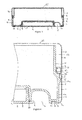
- FIG. 3 A cross-sectional view of the container is illustrated in Figure 3 , which shows the base 2 having a bottom or central wall 7 in which the central recess 4 extending towards the main storage space of the container 1 is formed.
- the central wall 7 of the base 2 further comprises a generally annular groove 8 for receiving a peripheral lip 9 of the cover 5, an outer annular recess 10 configured to hold a folded edge 11 of the metal outer sheath 6 and an outer annular lip 7a.
- an indentation 12 Located in the path of the annular groove 8, between the central recess 4 and the outer annular recess 10, is an indentation 12 which is formed to enable a user to insert a finger to facilitate removal of the cover 5.
- an upwardly extending side wall 13 formed from first and second integral portions 13a, 13b, the second portion 13b extending from the upper end of the first portion 13a and being disposed radially inwardly of the first portion 13a.
- the first and second portions are separated by a shoulder 13c.
- On the outer surface of the first portion 13a a circumferential protrusion 15 is formed and a bead 16 is formed on the outer surface of the second portion 13b.
- the protrusion 15 is formed with an upper horizontal surface 17 parallel to the central wall 7 of the base 2 and has a ramped lower surface 17a extending in a direction towards its horizontal surface 17.
- the cover 5 which closes the disposal compartment is configured to lie flush with the central wall 7. It comprises a circular bottom wall 19 provided with the peripheral lip 9 which is received in the annular groove 8 of the base 2 as previously described.
- a side wall 20 extends upwardly from the bottom wall 19 for a distance equal to the depth of the central recess 4 of the base 2 and is received therein when the cover 5 is attached to the container 1.
- the lid 3 comprises a top wall 25 having a peripheral side wall 26.
- An edge 27 of the side wall is coiled inwardly so as to form a flange 28 that engages with the bead 16 of the base 2 such that the lid 3 is releasably attachable to said base 2.
- the end of the peripheral side wall 26 sits on the shoulder between the first and second portions 13a, 13b of the base 2.
- the container 1 according to the present invention is further provided with the metal outer sheath 6 having an annular shape.
- Figure 4 shows an enlarged region of Figure 3 which illustrates the metal outer sheath 6 extending across part of the central wall 7 and the first portion 13a of the side wall 13 of the base 2 which is not inwardly displaced.
- the upper 30 and lower edges 11 of the metal outer sheath 6 are folded or doubled-back so as to create upper and lower folded end portions 11a, 30a that provide mechanical coupling with the base 2.
- the folded end portion 11a of the lower edge 11 is disposed in the annular recess 10 of the central wall 7 of the base 2 so that the metal outer sheath 6 extends across the outer annular lip 7a and lies flush with the central wall 7.
- the lower folded end portion 11a fits neatly in the annular recess 10 and is restricted from moving in a direction parallel to the central wall 7 of the base 2.
- the upper edge 30 abuts the horizontal surface 17 of the protrusion 15 of the side wall 13 of the base 2 such that the metal outer sheath 6 is prevented from moving downwards.
- the thickness of the upper folded end portion 30a also enables the metal outer sheath 6 to form a flush outer surface with the lid 3.
- the combination of the restricted mobility of the upper and lower folded edges 30, 11 of the metal outer sheath 6 secures the sheath 6 onto the base 2. Furthermore, the resilience of the metal enables the sheath 6 to be clipped on and off such that it may be removable or interchangeable.
- the base 2 When the metal outer sheath 6 is to be attached to the base, the base 2 is placed within the sheath so that the upper folded portion 30a contacts the ramped underside surface 17a of the protrusion 15. The metal outer sheath 6 and base 2 are then pressed together so that the metal outer sheath 6 resiliently deforms as it rides up the ramp. When the top of the ramp is reached, the folded edge 30 snaps over the protrusion 15 to hold the metal outer sheath 6 in position. At the same time, the other lower folded portion 11a seats in the annular recess 10. It will be appreciated that the side wall of the metal outer sheath 6 may deform and/or the upper folded portion 30a to enable it to pass over the protrusion 15 and snap into place.
- a disposal compartment may be formed in the plastic base 2 whilst the benefits of a metal container are also realised.
- the base 2 and cover 5 can be formed by injection moulding, which enables the container 1 to be easily formed with a disposal compartment without the typical drawbacks of metal including points of weakness at corners and edges.
- the metal outer sheath 6 attached to the base 2 provides additional strength to the container 1, as well as a surface for printing a brand and/or promotional material. In contrast to conventional plastic containers, this enables the surface of the metal outer sheath 6 to be printed prior to being formed into the annular shape allowing for the entire surface of the metal outer sheath to be printed if so desired.
- the base 2 is formed from plastic and the lid 3, cover 5 and the outer sheath 6 are made of metal so as to give the container an overall metallic appearance.
- the base, lid, cover and sheath can be formed from any material and in any combination of materials.
- the base and the lid can be made of plastic and the outer sheath from metal, or the outer sheath can be made of cardboard which provides a surface to enable print to be readily applied thereto, rather than providing additional stability.
- the whole container can be formed from plastic such that a plastic outer sheath provides additional stability to the container and allows for easy exchange of promotional material by interchanging the sheath.
- rubber can be used for the outer sheath such that it protects the base and offers a surface for printing promotional material.
- the disposal compartment can be formed in the lid instead of the base.
- the lid is then configured similarly to the central wall of the base as previously described, such that the metal outer sheath extends across part of the top wall and the peripheral side walls of the lid.
- a disposal compartment could be formed in both the lid and the base, in which case both the lid and the base would be provided with its own outer sheath.
- the container may not be provided with a disposal compartment, in which case the central wall of the base of the container will be visible through the outer sheath if the sheath extends only partly across the central wall, although the sheath may extend entirely across and completely cover the central wall.
- the outer sheath would still offer advantages over conventional containers in terms of enhanced rigidity and so as to provide, for example, a surface for printing prior to the sheath being formed into shape.
- the container has been described as having a circular cross-section it is not limited to this configuration and may be of other shapes.
- the container including the base, lid and metal outer sheath, may be oblong with rounded corners, oval or rectangular.
- the outer sheath may only extend partly around the circumference of the base, but still provide the aforementioned advantages.
- the container according to the present invention is configured to hold any type of tobacco products including smokeless products such as snus and snuff as well as loose tobacco for handrolled cigarettes or for pipes.
Abstract
Description
- The present invention relates to a container for storing tobacco products.
- Current packaging for tobacco products, in particular snus and snuff but also loose tobacco, generally comprises a container formed from a base and a lid. These containers are typically made from one type of material, such as metal or plastic, each of which have different advantages in terms of the manufacturing process and robustness of the container. For example, a metal container exhibits a greater robustness, strength and rigidity than a plastic container and allows print to be applied across the material surface before being formed into its final product shape. However, the manufacturing process of metal containers may create points of weakness at corners and edges, whereas plastic containers can be easily manufactured to a high level of detail by injection moulding.
- It is desirable to provide a container with advantages that would normally only be found with containers formed from different materials.
- It is also desirable to provide a container with a separate disposal compartment in either the lid or the base which is closable with a cover so that a user can temporarily store used snus for later disposal. Although it may be preferable to form the container from a particular material, that material may have certain inherent limitations making it difficult to provide the container with a disposal compartment.
- It is known from
W02008/135864 to provide a container for smokeless tobacco products having a metal base, a metal lid and a plastic ring received within and mechanically connected to the base that protrudes above the side wall of the base and which makes a friction fit with the lid. However, the configuration of the container does not allow for either the base or the lid to be provided with, for example, a disposal compartment. - The present invention seeks to provide a container for holding snus which overcomes or substantially alleviates the problems mentioned above and which combines different materials such that a container can be tailored to specific applications in terms of use, manufacturing advantages and cost effectiveness.
- According to the present invention, there is provided a container comprising two portions separable from each other to gain access to the contents of the container, each portion having a central wall with a peripheral side wall, at least one of said portions having an outer sheath attachable thereto that extends over the side wall and across a portion of the central wall.
- In a preferred embodiment, the outer sheath extends across only a periphery of the central wall adjacent to said peripheral side wall. If the container is circular, this provides the sheath with a circular opening through which the central wall of the base of the container is visible.
- Preferably, the portion to which the outer sheath is attachable comprises a recess in a region of the central wall not covered by said outer sheath so as to form a disposal compartment.
- Conveniently, the central wall of the portion to which the outer sheath is attached is formed with a groove in the region not covered by the outer sheath to receive a lip of a cover, said cover being releasably attachable to the central wall to close the disposal compartment.
- An indentation may be formed in the central wall of the portion of the container to which the outer sheath is attached to facilitate removal of said cover.
- In one embodiment, the outer sheath has a lower folded edge that locates against the central wall.
- Conveniently, the central wall includes an outer recess and the lower folded edge locates in said recess.
- Preferably, the peripheral side wall of the portion of the container to which the outer sheath is attachable is formed with a protrusion to locate the outer sheath on said portion.
- Conveniently, the outer sheath is slideable onto said portion, said protrusion having a ramped lower surface configured such that the outer sheath rides up said ramped surface and snaps over the protrusion to attach the outer sheath to said portion.
- In one embodiment, the outer sheath has an upper folded edge that slides up the ramped lower surface and snaps over the protrusion.
- The upper folded edge may be configured such that it resiliently deforms as the outer sheath slides up the ramped lower surface to enable the outer sheath to pass over the protrusion.
- The side wall of the portion to which an outer sheath is attachable may comprise a first portion and a second portion displaced radially inwardly from the first portion, said first and second portions being separated by a shoulder.
- In one embodiment, a bead is formed on said second portion that engages with a flange formed on the side wall of the other portion to maintain the container in a closed state.
- Preferably, the portion to which an outer sheath is attachable comprises a base and the other portion comprises a lid.
- In an alternative embodiment, the portion to which an outer sheath is attachable comprises a lid and the other portion comprises a base.
- The outer sheath may be removable from said portion.
- Preferably, the central wall is circular with cylindrical side walls and the outer sheath is annular.
- In one embodiment, the portion having an outer sheath is formed from plastic and said outer sheath is formed from metal.
- Embodiments of the present invention will now be described, by way of example only, and with reference to the following drawings, in which:
-
Figure 1 shows a perspective top view of a container according to the present invention; -
Figure 2 shows a perspective bottom view of the container ofFigure 1 ; -
Figure 3 shows a cross-sectional view of the container ofFigures 1 and 2 ; and -
Figure 4 shows an enhanced region of the cross-sectional view of the container ofFigure 3 . - Referring now to the drawings there is shown in
Figures 1 to 3 a container 1 comprising abase 2 and alid 3 which define a main storage space for holding snus. Thebase 2 further comprises a central recess 4 defining a space or disposal compartment for receiving consumed snus, which is closed by acover 5 as seen inFigure 2 and3 . At least thebase 2 is formed from a plastic material. Thebase 2 is also configured to receive a metalouter sheath 6 as will become apparent from the following description. - A cross-sectional view of the container is illustrated in
Figure 3 , which shows thebase 2 having a bottom or central wall 7 in which the central recess 4 extending towards the main storage space of the container 1 is formed. The central wall 7 of thebase 2 further comprises a generally annular groove 8 for receiving a peripheral lip 9 of thecover 5, an outerannular recess 10 configured to hold a foldededge 11 of the metalouter sheath 6 and an outerannular lip 7a. Located in the path of the annular groove 8, between the central recess 4 and the outerannular recess 10, is anindentation 12 which is formed to enable a user to insert a finger to facilitate removal of thecover 5. At the periphery of the central wall 7 of thebase 2 is an upwardly extendingside wall 13 formed from first and secondintegral portions 13a, 13b, the second portion 13b extending from the upper end of thefirst portion 13a and being disposed radially inwardly of thefirst portion 13a. The first and second portions are separated by a shoulder 13c. On the outer surface of thefirst portion 13a acircumferential protrusion 15 is formed and abead 16 is formed on the outer surface of the second portion 13b. Theprotrusion 15 is formed with an upperhorizontal surface 17 parallel to the central wall 7 of thebase 2 and has a rampedlower surface 17a extending in a direction towards itshorizontal surface 17. - The
cover 5 which closes the disposal compartment is configured to lie flush with the central wall 7. It comprises acircular bottom wall 19 provided with the peripheral lip 9 which is received in the annular groove 8 of thebase 2 as previously described. Aside wall 20 extends upwardly from thebottom wall 19 for a distance equal to the depth of the central recess 4 of thebase 2 and is received therein when thecover 5 is attached to the container 1. - The
lid 3 comprises atop wall 25 having aperipheral side wall 26. Anedge 27 of the side wall is coiled inwardly so as to form aflange 28 that engages with thebead 16 of thebase 2 such that thelid 3 is releasably attachable to saidbase 2. When thelid 3 is in position on thebase 2, the end of theperipheral side wall 26 sits on the shoulder between the first andsecond portions 13a, 13b of thebase 2. - The container 1 according to the present invention is further provided with the metal
outer sheath 6 having an annular shape.Figure 4 shows an enlarged region ofFigure 3 which illustrates the metalouter sheath 6 extending across part of the central wall 7 and thefirst portion 13a of theside wall 13 of thebase 2 which is not inwardly displaced. The upper 30 andlower edges 11 of the metalouter sheath 6 are folded or doubled-back so as to create upper and lower foldedend portions 11a, 30a that provide mechanical coupling with thebase 2. Moreover, the folded end portion 11a of thelower edge 11 is disposed in theannular recess 10 of the central wall 7 of thebase 2 so that the metalouter sheath 6 extends across the outerannular lip 7a and lies flush with the central wall 7. The lower folded end portion 11a fits neatly in theannular recess 10 and is restricted from moving in a direction parallel to the central wall 7 of thebase 2. The upper edge 30 abuts thehorizontal surface 17 of theprotrusion 15 of theside wall 13 of thebase 2 such that the metalouter sheath 6 is prevented from moving downwards. The thickness of the upper foldedend portion 30a also enables the metalouter sheath 6 to form a flush outer surface with thelid 3. The combination of the restricted mobility of the upper and lower foldededges 30, 11 of the metalouter sheath 6 secures thesheath 6 onto thebase 2. Furthermore, the resilience of the metal enables thesheath 6 to be clipped on and off such that it may be removable or interchangeable. - When the metal
outer sheath 6 is to be attached to the base, thebase 2 is placed within the sheath so that the upper foldedportion 30a contacts the rampedunderside surface 17a of theprotrusion 15. The metalouter sheath 6 andbase 2 are then pressed together so that the metalouter sheath 6 resiliently deforms as it rides up the ramp. When the top of the ramp is reached, the folded edge 30 snaps over theprotrusion 15 to hold the metalouter sheath 6 in position. At the same time, the other lower folded portion 11a seats in theannular recess 10. It will be appreciated that the side wall of the metalouter sheath 6 may deform and/or the upper foldedportion 30a to enable it to pass over theprotrusion 15 and snap into place. - As the metal
outer sheath 6 covers theentire side wall 13 of thebase 2 and extends around the lower edge of thebase 2, leaving an annular opening through which the central wall 7 of theplastic base 2 is accessible, a disposal compartment may be formed in theplastic base 2 whilst the benefits of a metal container are also realised. - The
base 2 andcover 5 can be formed by injection moulding, which enables the container 1 to be easily formed with a disposal compartment without the typical drawbacks of metal including points of weakness at corners and edges. The metalouter sheath 6 attached to thebase 2 provides additional strength to the container 1, as well as a surface for printing a brand and/or promotional material. In contrast to conventional plastic containers, this enables the surface of the metalouter sheath 6 to be printed prior to being formed into the annular shape allowing for the entire surface of the metal outer sheath to be printed if so desired. - In the illustrated embodiment, the
base 2 is formed from plastic and thelid 3,cover 5 and theouter sheath 6 are made of metal so as to give the container an overall metallic appearance. However, it should be appreciated that the base, lid, cover and sheath can be formed from any material and in any combination of materials. For example, the base and the lid can be made of plastic and the outer sheath from metal, or the outer sheath can be made of cardboard which provides a surface to enable print to be readily applied thereto, rather than providing additional stability. Alternatively, the whole container can be formed from plastic such that a plastic outer sheath provides additional stability to the container and allows for easy exchange of promotional material by interchanging the sheath. Furthermore, rubber can be used for the outer sheath such that it protects the base and offers a surface for printing promotional material. - It is also envisaged that the disposal compartment can be formed in the lid instead of the base. The lid is then configured similarly to the central wall of the base as previously described, such that the metal outer sheath extends across part of the top wall and the peripheral side walls of the lid. In another embodiment, a disposal compartment could be formed in both the lid and the base, in which case both the lid and the base would be provided with its own outer sheath.
- It is also envisaged that the container may not be provided with a disposal compartment, in which case the central wall of the base of the container will be visible through the outer sheath if the sheath extends only partly across the central wall, although the sheath may extend entirely across and completely cover the central wall. In this embodiment, the outer sheath would still offer advantages over conventional containers in terms of enhanced rigidity and so as to provide, for example, a surface for printing prior to the sheath being formed into shape.
- It will be appreciated that although the container has been described as having a circular cross-section it is not limited to this configuration and may be of other shapes. For example, the container, including the base, lid and metal outer sheath, may be oblong with rounded corners, oval or rectangular. Furthermore, it will also be appreciated that the outer sheath may only extend partly around the circumference of the base, but still provide the aforementioned advantages.
- It should also be realised that the container according to the present invention is configured to hold any type of tobacco products including smokeless products such as snus and snuff as well as loose tobacco for handrolled cigarettes or for pipes.
- Although embodiments of the invention have been shown and described, it will be appreciated by those persons skilled in the art that the foregoing description should be regarded as a description of preferred embodiments only and that other embodiments that fall within the scope of the appended claims are considered to form part of this disclosure.
Claims (18)
- A container comprising two portions separable from each other to gain access to the contents of the container, each portion having a central wall with a peripheral side wall, at least one of said portions having an outer sheath attachable thereto such that it extends over the side wall and across a portion of the central wall.
- A container according to claim 1, wherein the outer sheath extends across only a periphery of the central wall adjacent to said peripheral side wall.
- A container according to claim 1 or 2, wherein the portion to which the outer sheath is attachable comprises a recess in a region of the central wall not covered by said outer sheath so as to form a disposal compartment.
- A container according to claim 3, wherein the central wall of the portion to which the outer sheath is attached is formed with a groove in the region not covered by the outer sheath to receive a lip of a cover, said cover being releasably attachable to the central wall to close the disposal compartment.
- A container according to claim 4, wherein an indentation is formed in the central wall of the portion of the container to which the outer sheath is attached to facilitate removal of said cover.
- A container according to any of claims 1 to 5, wherein the outer sheath has a lower folded edge that locates against the central wall.
- A container according to claim 6, wherein the central wall includes an outer recess and the lower folded edge locates in said recess.
- A container according to any preceding claim, wherein the peripheral side wall of the portion of the container to which the outer sheath is attachable is formed with a protrusion to locate the outer sheath on said portion.
- A container according to claim 8, wherein the outer sheath is slideable onto said portion, said protrusion having a ramped lower surface configured such that the outer sheath rides up said ramped surface and snaps over the protrusion to attach the outer sheath to said portion.
- A container according to claim 9, wherein the outer sheath has an upper folded edge that slides up the ramped lower surface and snaps over the protrusion.
- A container according to claim 10, wherein the upper folded edge is configured such that it resiliently deforms as the outer sheath slides up the ramped lower surface to enable the outer sheath to pass over the protrusion.
- A container according to any preceding claim, wherein the side wall of the portion to which an outer sheath is attachable comprises a first portion and a second portion displaced radially inwardly from the first portion, said first and second portions being separated by a shoulder.
- A container according to claim 12, wherein a bead is formed on said second portion that engages with a flange formed on the side wall of the other portion to maintain the container in a closed state.
- A container according to any preceding claim, wherein the portion to which an outer sheath is attachable comprises a base and the other portion comprises a lid.
- A container according to claims 1 to 13, wherein the portion to which an outer sheath is attachable comprises a lid and the other portion comprises a base.
- A container according to any preceding claim, wherein the outer sheath is removable from said portion.
- A container according to any preceding claim wherein the central wall is circular with cylindrical side walls and the outer sheath is annular.
- A container according to any preceding claim, wherein the portion having an outer sheath is formed from plastic and said outer sheath is formed from metal.
Applications Claiming Priority (1)
| Application Number | Priority Date | Filing Date | Title |
|---|---|---|---|
| GBGB0905522.9A GB0905522D0 (en) | 2009-03-31 | 2009-03-31 | Container |
Publications (2)
| Publication Number | Publication Date |
|---|---|
| EP2236433A1 true EP2236433A1 (en) | 2010-10-06 |
| EP2236433B1 EP2236433B1 (en) | 2012-05-09 |
Family
ID=40672021
Family Applications (1)
| Application Number | Title | Priority Date | Filing Date |
|---|---|---|---|
| EP10157026A Not-in-force EP2236433B1 (en) | 2009-03-31 | 2010-03-19 | Container |
Country Status (6)
| Country | Link |
|---|---|
| EP (1) | EP2236433B1 (en) |
| AT (1) | ATE556950T1 (en) |
| CA (1) | CA2697595A1 (en) |
| DK (1) | DK2236433T3 (en) |
| GB (1) | GB0905522D0 (en) |
| ZA (1) | ZA201002187B (en) |
Cited By (7)
| Publication number | Priority date | Publication date | Assignee | Title |
|---|---|---|---|---|
| US20110290682A1 (en) * | 2008-11-28 | 2011-12-01 | Paul Gibson | Container |
| WO2013187782A1 (en) * | 2012-06-15 | 2013-12-19 | Rml Engineering Limited | Tamper evident container |
| WO2014143788A1 (en) * | 2013-03-15 | 2014-09-18 | Crown Packaging Technology, Inc. | Tobacco container with plastic insert |
| JP2016521970A (en) * | 2013-04-18 | 2016-07-28 | ブリティッシュ アメリカン タバコ (インヴェストメンツ) リミテッドBritish American Tobacco (Investments) Limited | container |
| US10173825B1 (en) | 2017-04-07 | 2019-01-08 | Paul Anthony Ercole | Powder container and dispenser |
| US11076640B2 (en) | 2016-08-23 | 2021-08-03 | Winnington Ab | Product container comprising transparent member |
| WO2022263038A1 (en) * | 2021-06-14 | 2022-12-22 | Sävjo Plastic Ab | A snus container, a method of manufacturing a snus container and a mould |
Citations (3)
| Publication number | Priority date | Publication date | Assignee | Title |
|---|---|---|---|---|
| GB2152468A (en) | 1983-12-06 | 1985-08-07 | Oreal | An external casing for a container such as a perfume bottle or atomiser |
| EP1415928A1 (en) * | 2002-10-29 | 2004-05-06 | Qualipac | Bottle for fluid |
| WO2005016036A1 (en) * | 2003-08-18 | 2005-02-24 | Gallaher Snus Ab | Snuff-box lid |
-
2009
- 2009-03-31 GB GBGB0905522.9A patent/GB0905522D0/en not_active Ceased
-
2010
- 2010-03-19 AT AT10157026T patent/ATE556950T1/en active
- 2010-03-19 EP EP10157026A patent/EP2236433B1/en not_active Not-in-force
- 2010-03-19 DK DK10157026.5T patent/DK2236433T3/en active
- 2010-03-23 CA CA2697595A patent/CA2697595A1/en not_active Abandoned
- 2010-03-26 ZA ZA2010/02187A patent/ZA201002187B/en unknown
Patent Citations (3)
| Publication number | Priority date | Publication date | Assignee | Title |
|---|---|---|---|---|
| GB2152468A (en) | 1983-12-06 | 1985-08-07 | Oreal | An external casing for a container such as a perfume bottle or atomiser |
| EP1415928A1 (en) * | 2002-10-29 | 2004-05-06 | Qualipac | Bottle for fluid |
| WO2005016036A1 (en) * | 2003-08-18 | 2005-02-24 | Gallaher Snus Ab | Snuff-box lid |
Cited By (11)
| Publication number | Priority date | Publication date | Assignee | Title |
|---|---|---|---|---|
| US20110290682A1 (en) * | 2008-11-28 | 2011-12-01 | Paul Gibson | Container |
| US8701881B2 (en) * | 2008-11-28 | 2014-04-22 | British American Tobacco (Investments) Limited | Container |
| WO2013187782A1 (en) * | 2012-06-15 | 2013-12-19 | Rml Engineering Limited | Tamper evident container |
| WO2014143788A1 (en) * | 2013-03-15 | 2014-09-18 | Crown Packaging Technology, Inc. | Tobacco container with plastic insert |
| US9265287B2 (en) | 2013-03-15 | 2016-02-23 | Crown Packaging Technology, Inc. | Tobacco container with plastic insert |
| JP2016521970A (en) * | 2013-04-18 | 2016-07-28 | ブリティッシュ アメリカン タバコ (インヴェストメンツ) リミテッドBritish American Tobacco (Investments) Limited | container |
| JP2018134092A (en) * | 2013-04-18 | 2018-08-30 | ブリティッシュ アメリカン タバコ (インヴェストメンツ) リミテッドBritish American Tobacco (Investments) Limited | container |
| JP2021090432A (en) * | 2013-04-18 | 2021-06-17 | ブリティッシュ アメリカン タバコ (インヴェストメンツ) リミテッドBritish American Tobacco (Investments) Limited | container |
| US11076640B2 (en) | 2016-08-23 | 2021-08-03 | Winnington Ab | Product container comprising transparent member |
| US10173825B1 (en) | 2017-04-07 | 2019-01-08 | Paul Anthony Ercole | Powder container and dispenser |
| WO2022263038A1 (en) * | 2021-06-14 | 2022-12-22 | Sävjo Plastic Ab | A snus container, a method of manufacturing a snus container and a mould |
Also Published As
| Publication number | Publication date |
|---|---|
| ATE556950T1 (en) | 2012-05-15 |
| CA2697595A1 (en) | 2010-09-30 |
| GB0905522D0 (en) | 2009-05-13 |
| DK2236433T3 (en) | 2012-06-18 |
| EP2236433B1 (en) | 2012-05-09 |
| ZA201002187B (en) | 2013-09-25 |
Similar Documents
| Publication | Publication Date | Title |
|---|---|---|
| EP2236433B1 (en) | Container | |
| EP2358610B1 (en) | Container | |
| EP2361198B1 (en) | Container for snus | |
| US20170267417A1 (en) | Lid for tobacco can | |
| CA2684761C (en) | Tobacco container with insert | |
| EP2935041B1 (en) | Measuring scoop and support for a container | |
| EP2349853B1 (en) | Container | |
| US20130160265A1 (en) | Container/lid assembly | |
| US7398893B2 (en) | Cup and lid combination | |
| MX2007002120A (en) | Non-cylindrical container and lid. | |
| EP2370324B1 (en) | Container with hinge lid | |
| EP2429322B1 (en) | Container | |
| RU2769208C2 (en) | Aerosol-generating article receptacle | |
| JP5103303B2 (en) | Sealed container | |
| CA2535941A1 (en) | Cover assembly for a food container | |
| JP2008024338A (en) | Packaging container composed of container body having tab and lid | |
| CA2888075A1 (en) | Tamper-evident tab thermoformed packaging |
Legal Events
| Date | Code | Title | Description |
|---|---|---|---|
| PUAI | Public reference made under article 153(3) epc to a published international application that has entered the european phase |
Free format text: ORIGINAL CODE: 0009012 |
|
| AK | Designated contracting states |
Kind code of ref document: A1 Designated state(s): AT BE BG CH CY CZ DE DK EE ES FI FR GB GR HR HU IE IS IT LI LT LU LV MC MK MT NL NO PL PT RO SE SI SK SM TR |
|
| AX | Request for extension of the european patent |
Extension state: AL BA ME RS |
|
| 17P | Request for examination filed |
Effective date: 20101027 |
|
| 17Q | First examination report despatched |
Effective date: 20110609 |
|
| RIC1 | Information provided on ipc code assigned before grant |
Ipc: B65D 25/34 20060101ALI20110830BHEP Ipc: A24F 23/00 20060101ALI20110830BHEP Ipc: B65D 43/02 20060101AFI20110830BHEP Ipc: B65D 51/28 20060101ALI20110830BHEP |
|
| GRAP | Despatch of communication of intention to grant a patent |
Free format text: ORIGINAL CODE: EPIDOSNIGR1 |
|
| RIN1 | Information on inventor provided before grant (corrected) |
Inventor name: MCKENZIE, AARON Inventor name: GIBSON, PAUL |
|
| GRAS | Grant fee paid |
Free format text: ORIGINAL CODE: EPIDOSNIGR3 |
|
| GRAA | (expected) grant |
Free format text: ORIGINAL CODE: 0009210 |
|
| AK | Designated contracting states |
Kind code of ref document: B1 Designated state(s): AT BE BG CH CY CZ DE DK EE ES FI FR GB GR HR HU IE IS IT LI LT LU LV MC MK MT NL NO PL PT RO SE SI SK SM TR |
|
| REG | Reference to a national code |
Ref country code: GB Ref legal event code: FG4D |
|
| REG | Reference to a national code |
Ref country code: AT Ref legal event code: REF Ref document number: 556950 Country of ref document: AT Kind code of ref document: T Effective date: 20120515 Ref country code: CH Ref legal event code: EP |
|
| REG | Reference to a national code |
Ref country code: IE Ref legal event code: FG4D |
|
| REG | Reference to a national code |
Ref country code: DK Ref legal event code: T3 |
|
| REG | Reference to a national code |
Ref country code: DE Ref legal event code: R096 Ref document number: 602010001349 Country of ref document: DE Effective date: 20120719 |
|
| REG | Reference to a national code |
Ref country code: SE Ref legal event code: TRGR |
|
| REG | Reference to a national code |
Ref country code: NL Ref legal event code: VDEP Effective date: 20120509 |
|
| REG | Reference to a national code |
Ref country code: NO Ref legal event code: T2 Effective date: 20120509 |
|
| REG | Reference to a national code |
Ref country code: LT Ref legal event code: MG4D Effective date: 20120509 |
|
| PG25 | Lapsed in a contracting state [announced via postgrant information from national office to epo] |
Ref country code: CY Free format text: LAPSE BECAUSE OF FAILURE TO SUBMIT A TRANSLATION OF THE DESCRIPTION OR TO PAY THE FEE WITHIN THE PRESCRIBED TIME-LIMIT Effective date: 20120509 Ref country code: PL Free format text: LAPSE BECAUSE OF FAILURE TO SUBMIT A TRANSLATION OF THE DESCRIPTION OR TO PAY THE FEE WITHIN THE PRESCRIBED TIME-LIMIT Effective date: 20120509 Ref country code: LT Free format text: LAPSE BECAUSE OF FAILURE TO SUBMIT A TRANSLATION OF THE DESCRIPTION OR TO PAY THE FEE WITHIN THE PRESCRIBED TIME-LIMIT Effective date: 20120509 Ref country code: IS Free format text: LAPSE BECAUSE OF FAILURE TO SUBMIT A TRANSLATION OF THE DESCRIPTION OR TO PAY THE FEE WITHIN THE PRESCRIBED TIME-LIMIT Effective date: 20120909 Ref country code: FI Free format text: LAPSE BECAUSE OF FAILURE TO SUBMIT A TRANSLATION OF THE DESCRIPTION OR TO PAY THE FEE WITHIN THE PRESCRIBED TIME-LIMIT Effective date: 20120509 |
|
| REG | Reference to a national code |
Ref country code: AT Ref legal event code: MK05 Ref document number: 556950 Country of ref document: AT Kind code of ref document: T Effective date: 20120509 |
|
| PG25 | Lapsed in a contracting state [announced via postgrant information from national office to epo] |
Ref country code: GR Free format text: LAPSE BECAUSE OF FAILURE TO SUBMIT A TRANSLATION OF THE DESCRIPTION OR TO PAY THE FEE WITHIN THE PRESCRIBED TIME-LIMIT Effective date: 20120810 Ref country code: SI Free format text: LAPSE BECAUSE OF FAILURE TO SUBMIT A TRANSLATION OF THE DESCRIPTION OR TO PAY THE FEE WITHIN THE PRESCRIBED TIME-LIMIT Effective date: 20120509 Ref country code: PT Free format text: LAPSE BECAUSE OF FAILURE TO SUBMIT A TRANSLATION OF THE DESCRIPTION OR TO PAY THE FEE WITHIN THE PRESCRIBED TIME-LIMIT Effective date: 20120910 Ref country code: LV Free format text: LAPSE BECAUSE OF FAILURE TO SUBMIT A TRANSLATION OF THE DESCRIPTION OR TO PAY THE FEE WITHIN THE PRESCRIBED TIME-LIMIT Effective date: 20120509 Ref country code: HR Free format text: LAPSE BECAUSE OF FAILURE TO SUBMIT A TRANSLATION OF THE DESCRIPTION OR TO PAY THE FEE WITHIN THE PRESCRIBED TIME-LIMIT Effective date: 20120509 |
|
| PG25 | Lapsed in a contracting state [announced via postgrant information from national office to epo] |
Ref country code: BE Free format text: LAPSE BECAUSE OF FAILURE TO SUBMIT A TRANSLATION OF THE DESCRIPTION OR TO PAY THE FEE WITHIN THE PRESCRIBED TIME-LIMIT Effective date: 20120509 |
|
| PG25 | Lapsed in a contracting state [announced via postgrant information from national office to epo] |
Ref country code: SK Free format text: LAPSE BECAUSE OF FAILURE TO SUBMIT A TRANSLATION OF THE DESCRIPTION OR TO PAY THE FEE WITHIN THE PRESCRIBED TIME-LIMIT Effective date: 20120509 Ref country code: NL Free format text: LAPSE BECAUSE OF FAILURE TO SUBMIT A TRANSLATION OF THE DESCRIPTION OR TO PAY THE FEE WITHIN THE PRESCRIBED TIME-LIMIT Effective date: 20120509 Ref country code: AT Free format text: LAPSE BECAUSE OF FAILURE TO SUBMIT A TRANSLATION OF THE DESCRIPTION OR TO PAY THE FEE WITHIN THE PRESCRIBED TIME-LIMIT Effective date: 20120509 Ref country code: EE Free format text: LAPSE BECAUSE OF FAILURE TO SUBMIT A TRANSLATION OF THE DESCRIPTION OR TO PAY THE FEE WITHIN THE PRESCRIBED TIME-LIMIT Effective date: 20120509 Ref country code: CZ Free format text: LAPSE BECAUSE OF FAILURE TO SUBMIT A TRANSLATION OF THE DESCRIPTION OR TO PAY THE FEE WITHIN THE PRESCRIBED TIME-LIMIT Effective date: 20120509 Ref country code: RO Free format text: LAPSE BECAUSE OF FAILURE TO SUBMIT A TRANSLATION OF THE DESCRIPTION OR TO PAY THE FEE WITHIN THE PRESCRIBED TIME-LIMIT Effective date: 20120509 |
|
| PG25 | Lapsed in a contracting state [announced via postgrant information from national office to epo] |
Ref country code: IT Free format text: LAPSE BECAUSE OF FAILURE TO SUBMIT A TRANSLATION OF THE DESCRIPTION OR TO PAY THE FEE WITHIN THE PRESCRIBED TIME-LIMIT Effective date: 20120509 |
|
| PLBE | No opposition filed within time limit |
Free format text: ORIGINAL CODE: 0009261 |
|
| STAA | Information on the status of an ep patent application or granted ep patent |
Free format text: STATUS: NO OPPOSITION FILED WITHIN TIME LIMIT |
|
| 26N | No opposition filed |
Effective date: 20130212 |
|
| PG25 | Lapsed in a contracting state [announced via postgrant information from national office to epo] |
Ref country code: ES Free format text: LAPSE BECAUSE OF FAILURE TO SUBMIT A TRANSLATION OF THE DESCRIPTION OR TO PAY THE FEE WITHIN THE PRESCRIBED TIME-LIMIT Effective date: 20120820 |
|
| REG | Reference to a national code |
Ref country code: DE Ref legal event code: R097 Ref document number: 602010001349 Country of ref document: DE Effective date: 20130212 |
|
| PG25 | Lapsed in a contracting state [announced via postgrant information from national office to epo] |
Ref country code: BG Free format text: LAPSE BECAUSE OF FAILURE TO SUBMIT A TRANSLATION OF THE DESCRIPTION OR TO PAY THE FEE WITHIN THE PRESCRIBED TIME-LIMIT Effective date: 20120809 |
|
| PG25 | Lapsed in a contracting state [announced via postgrant information from national office to epo] |
Ref country code: MC Free format text: LAPSE BECAUSE OF NON-PAYMENT OF DUE FEES Effective date: 20130331 |
|
| REG | Reference to a national code |
Ref country code: FR Ref legal event code: ST Effective date: 20131129 |
|
| REG | Reference to a national code |
Ref country code: IE Ref legal event code: MM4A |
|
| PG25 | Lapsed in a contracting state [announced via postgrant information from national office to epo] |
Ref country code: IE Free format text: LAPSE BECAUSE OF NON-PAYMENT OF DUE FEES Effective date: 20130319 Ref country code: FR Free format text: LAPSE BECAUSE OF NON-PAYMENT OF DUE FEES Effective date: 20130402 |
|
| PGFP | Annual fee paid to national office [announced via postgrant information from national office to epo] |
Ref country code: DK Payment date: 20140319 Year of fee payment: 5 Ref country code: DE Payment date: 20140328 Year of fee payment: 5 |
|
| PG25 | Lapsed in a contracting state [announced via postgrant information from national office to epo] |
Ref country code: MT Free format text: LAPSE BECAUSE OF FAILURE TO SUBMIT A TRANSLATION OF THE DESCRIPTION OR TO PAY THE FEE WITHIN THE PRESCRIBED TIME-LIMIT Effective date: 20120509 |
|
| REG | Reference to a national code |
Ref country code: CH Ref legal event code: PL |
|
| GBPC | Gb: european patent ceased through non-payment of renewal fee |
Effective date: 20140319 |
|
| PG25 | Lapsed in a contracting state [announced via postgrant information from national office to epo] |
Ref country code: CH Free format text: LAPSE BECAUSE OF NON-PAYMENT OF DUE FEES Effective date: 20140331 Ref country code: GB Free format text: LAPSE BECAUSE OF NON-PAYMENT OF DUE FEES Effective date: 20140319 Ref country code: LI Free format text: LAPSE BECAUSE OF NON-PAYMENT OF DUE FEES Effective date: 20140331 |
|
| PG25 | Lapsed in a contracting state [announced via postgrant information from national office to epo] |
Ref country code: SM Free format text: LAPSE BECAUSE OF FAILURE TO SUBMIT A TRANSLATION OF THE DESCRIPTION OR TO PAY THE FEE WITHIN THE PRESCRIBED TIME-LIMIT Effective date: 20120509 |
|
| PG25 | Lapsed in a contracting state [announced via postgrant information from national office to epo] |
Ref country code: TR Free format text: LAPSE BECAUSE OF FAILURE TO SUBMIT A TRANSLATION OF THE DESCRIPTION OR TO PAY THE FEE WITHIN THE PRESCRIBED TIME-LIMIT Effective date: 20120509 |
|
| PG25 | Lapsed in a contracting state [announced via postgrant information from national office to epo] |
Ref country code: MK Free format text: LAPSE BECAUSE OF FAILURE TO SUBMIT A TRANSLATION OF THE DESCRIPTION OR TO PAY THE FEE WITHIN THE PRESCRIBED TIME-LIMIT Effective date: 20120509 Ref country code: HU Free format text: LAPSE BECAUSE OF FAILURE TO SUBMIT A TRANSLATION OF THE DESCRIPTION OR TO PAY THE FEE WITHIN THE PRESCRIBED TIME-LIMIT; INVALID AB INITIO Effective date: 20100319 Ref country code: LU Free format text: LAPSE BECAUSE OF NON-PAYMENT OF DUE FEES Effective date: 20130319 |
|
| REG | Reference to a national code |
Ref country code: DE Ref legal event code: R119 Ref document number: 602010001349 Country of ref document: DE |
|
| REG | Reference to a national code |
Ref country code: DK Ref legal event code: EBP Effective date: 20150331 |
|
| PG25 | Lapsed in a contracting state [announced via postgrant information from national office to epo] |
Ref country code: DE Free format text: LAPSE BECAUSE OF NON-PAYMENT OF DUE FEES Effective date: 20151001 |
|
| PG25 | Lapsed in a contracting state [announced via postgrant information from national office to epo] |
Ref country code: DK Free format text: LAPSE BECAUSE OF NON-PAYMENT OF DUE FEES Effective date: 20150331 |
|
| PGFP | Annual fee paid to national office [announced via postgrant information from national office to epo] |
Ref country code: NO Payment date: 20200326 Year of fee payment: 11 Ref country code: SE Payment date: 20200323 Year of fee payment: 11 |
|
| REG | Reference to a national code |
Ref country code: NO Ref legal event code: MMEP |
|
| PG25 | Lapsed in a contracting state [announced via postgrant information from national office to epo] |
Ref country code: NO Free format text: LAPSE BECAUSE OF NON-PAYMENT OF DUE FEES Effective date: 20210331 Ref country code: SE Free format text: LAPSE BECAUSE OF NON-PAYMENT OF DUE FEES Effective date: 20210320 |
|
| P01 | Opt-out of the competence of the unified patent court (upc) registered |
Effective date: 20230504 |