EP2236414B1 - Tragschrauber - Google Patents
Tragschrauber Download PDFInfo
- Publication number
- EP2236414B1 EP2236414B1 EP10002481.9A EP10002481A EP2236414B1 EP 2236414 B1 EP2236414 B1 EP 2236414B1 EP 10002481 A EP10002481 A EP 10002481A EP 2236414 B1 EP2236414 B1 EP 2236414B1
- Authority
- EP
- European Patent Office
- Prior art keywords
- rotor
- damping
- damping device
- support structure
- fact
- Prior art date
- Legal status (The legal status is an assumption and is not a legal conclusion. Google has not performed a legal analysis and makes no representation as to the accuracy of the status listed.)
- Not-in-force
Links
Images


Classifications
-
- B—PERFORMING OPERATIONS; TRANSPORTING
- B64—AIRCRAFT; AVIATION; COSMONAUTICS
- B64C—AEROPLANES; HELICOPTERS
- B64C27/00—Rotorcraft; Rotors peculiar thereto
- B64C27/02—Gyroplanes
- B64C27/028—Other constructional elements; Rotor balancing
-
- B—PERFORMING OPERATIONS; TRANSPORTING
- B64—AIRCRAFT; AVIATION; COSMONAUTICS
- B64C—AEROPLANES; HELICOPTERS
- B64C27/00—Rotorcraft; Rotors peculiar thereto
- B64C27/001—Vibration damping devices
Definitions
- the invention relates to a gyroplane with a Nutzlastability in the form of a seat, a rotor and a rotor connecting the payload with the supporting structure.
- Such gyrocopters are used for example as an air sports device.
- a disadvantage of known gyroplanes is that especially longer flights in the pilot can lead to fatigue.
- the invention has for its object to provide a gyroplane that can be flown particularly fatigue-free.
- the invention solves the problem by a gyroplane according to claim 1.
- An advantage of the invention is that the provision of the damping device suppresses vibrations coming from the rotor, which leads to a fatigue-poor flying. It has been found that vibrations from the rotor significantly contribute to the fatigue of the pilot.
- the gyroplane according to the invention can be flown particularly gentle on the joints.
- the intervertebral discs of the pilot are relieved compared to known gyroscopes, since they are less heavily loaded by vibrations.
- the payload intake is understood in particular to mean a pilot's seat for a pilot.
- the payload receptacle may include one, two or three pilot seats.
- the invention is also suitable for model size gyroplane.
- the payload can be, for example, a holder for a camera or another sensor.
- the invention is particularly well suited for gyroplanes which are designed for passenger transport.
- a support structure is understood in particular the totality of all elements that connect the rotor with the payload recording so that the load of the payload is absorbed. It may be, for example, a linkage, a single support tube, a system of support tube and linkage, or the like.
- the gyroplane preferably comprises a rotor head which is not part of the support structure and is arranged between the support structure, which may also be referred to as a fuselage, and the rotor.
- the rotor head comprises those components which serve to actuate the rotor.
- the Damping device of the hull Preferably, the Damping device of the hull.
- the support structure comprises a damping device for damping vibrations emanating from the rotor
- the support structure has a first section with a first rigidity, a second section with a second rigidity and a third section with a third rigidity wherein the second portion is disposed between the first and third portions and has a rigidity smaller than that of the first portion and that of the third portion.
- the rigidity of the second portion in particular less than half the rigidity of the first portion and the third portion.
- the second section is also designed such that a relative movement of the first section and the third section is actively and / or passively damped.
- the support structure has a first portion with a first rigidity
- the first portion has the first stiffness with respect to a vibration in a first plane, ie the resistance which the support structure opposes to deformation in this plane
- the power flow from the rotor to the payload receiver is then followed by a second section with a second, smaller rigidity and a third section with a third rigidity.
- These stiffnesses also refer to a deflection in the same plane.
- the damping device for vibrations emanating from the rotor is understood in particular to mean any device which is designed such that at cruising speed, that is to say at the highest permanently possible speed, the vibrations emanating from the rotor are reduced by more than 80% in at least one vibration plane. This means that the amplitude of the vibration at the payload is only 0.2 times as large as without the damping device.
- a damping device is to be understood as an apparatus which reduces a vibration emanating from the rotor by at least partially converting an inherent energy of the vibration into heat.
- the gyrocopter has a center of gravity during operation, the damping device being disposed at a height between a center of gravity height of the center of mass and a rotor height of the rotor.
- the damping device is arranged adjacent to the rotor.
- the center of gravity refers to the gyrocopter with payload, so for example with pilot.
- the damping device is designed such that it damps vibration of the rotor about a transverse axis of the gyroscope. Such vibration leads to an up and down vibration at the pilot's seat, which is particularly undesirable. It can be provided that the damping device for vibrations around the longitudinal axis has substantially no damping effect. Such vibrations lead to a torsional vibration of the pilot's seat to a center of gravity of the pilot, which is perceived as a low stress. In addition, the rigidity with respect to a deformation in the plane perpendicular to the longitudinal axis leads to small relative movements of the rotor to the support structure.
- the damping device comprises at least one active damping element.
- An active damping element is to be understood in particular as meaning an actuator which can exert forces on two parts of the joint via an energy supply, which are thus selected are that emanating from the rotor vibrations reach the payload only weakened.
- the active damping element may be, for example, a piezoactuator or a magnetostrictive actuator.
- the active damping element may also be an actively adjustable damping element, in which the damping effect, for example electrically by applying a voltage or a current, can be adjusted.
- the damping device comprises at least one passive damping element.
- a component which converts an elastic deformation into a high proportion of heat. It may, for example, be a rubber-elastic element.
- a fluid-containing damper can be used, for example a hydraulic damper or a pneumatic damper. In such fluid dampers, movement between two suspension points of the fluid damper causes a fluid to be moved from one chamber of the fluid damper to another while flowing through a restriction so that the fluid loses energy as it flows through.
- the fluid may be a liquid or a gas.
- the damping device has an adjustable spring constant.
- the damping device has an elastic element that can be prestressed.
- a damping element have a non-linear dependence of the restoring force of the deflection. This is the case, for example, with rubber-elastic damping elements or McKibben's muscles.
- the damping device is designed so that a first natural frequency of the support structure is at least 14 hertz. It has been shown that such a Sufficient safety can be achieved in the operation of the gyrocopter.
- the damping device is designed so that the natural frequency of the support structure for a vibration in a plane perpendicular to the longitudinal axis of the gyroscope is at least 14 hertz. It is possible that the damping device is designed such that the natural frequency is below 14 hertz, for example for a vibration perpendicular to the transverse axis.
- the support element to which the bolt is attached the support element to which the sleeve is attached, at least partially surrounds.
- a vibration in the longitudinal direction of the support elements is particularly effectively damped. Vibrations of the two support elements transverse to each other, however, are transmitted via the direct contact of the two support elements. Thus, a high stability in the transverse direction is obtained.
- the gyroplane has a hull and a rotor head tiltable relative to the hull and a hydraulic control device for tilting the rotor head relative to the hull.
- a gyroplane can also have a damping device, but this is not necessary.
- Gyroplanes are known in which the rotor head is connected by means of control rods with a joystick. If the joystick is moved, this movement is transmitted by means of the control rods to the rotor head and thereby tilted. Depending on whether the rotor head is tilted in flight about a pitch axis or a roll axis, the gyrocopter accelerates forward or to the side.
- a disadvantage of known gyroplanes is that it is not possible to decouple the rotor head from the hull so that an entry of vibrations of the rotor head is reduced to the fuselage without starting to vibrate due to the decoupling of the joystick.
- An advantage of this gyroplane is that a vibration of the rotor head is transmitted relative to the hull of the gyroplane via the hydraulic control device.
- the hydraulic control device has a higher damping than a mechanical connection, so that the control stick is particularly quiet. This increases the comfort of flying. Furthermore, the reduced vibration leads to less fatigue in the pilot and thus to greater safety.
- a hydraulic control device can be easily realized with a reduction. This in turn has the advantage that the Gyroplane less sensitive to small movements of the joystick responded.
- the hydraulic control device can be designed so that hydraulic lines are attached to aerodynamically favorable location, for example in the lee of the fuselage. This lowers the aerodynamic drag of the gyrocopter and thus its consumption.
- the rotor head that unit of the gyro, which connects the rotor articulated with the rigid hull.
- the rotor head is that component to which the rotor is fastened and by means of which the rotor can be pivoted relative to the hull.
- the hydraulic control device is understood to be any control device in which a movement of the control stick is transmitted to the rotor head in at least one direction by means of a hydraulic fluid. It is possible, but not necessary, for the movements of the joystick to be transmitted both in the longitudinal direction and in the transverse direction via the hydraulic fluids. Thus, it is quite conceivable that a movement of the joystick in the transverse direction is transmitted via a hydraulic fluid, whereas a movement in the longitudinal direction is mechanically transmitted. Movement of the joystick in the longitudinal direction refers to a movement away from the pilot or towards him, which corresponds to a movement in the longitudinal direction of the gyrocopter.
- the control device has a pressure holder.
- a pressure holder is understood to mean a device which is designed such that a hydraulic pressure, below which the hydraulic fluid is located, is maintained above a minimum hydraulic pressure. This prevents a possibly existing gas bubble in the hydraulic fluid from expanding when a component filled with hydraulic fluid expands thermally. Such a gas bubble would adversely affect the responsiveness of the control device and lead to game play. By the pressure holder a high and always good response of the control device is ensured.
- the first pressure holder has a first pressure gas chamber filled with pressurized gas under gas pressure, a first hydraulic fluid chamber filled with hydraulic fluid and a diaphragm which separates the first pressure gas chamber from the first hydraulic fluid chamber such that the gas pressure is transmitted to the hydraulic fluid.
- a pressure holder is particularly easy to manufacture, operate safely and maintain well.
- the control device includes a first hydraulic line connecting a first end of the control cylinder to a first end of the actuator cylinder, a second hydraulic line connecting a second end of the control cylinder to a second end of the actuator cylinder, and a connection valve for connecting and disconnecting the first hydraulic line and second hydraulic line.
- a connection valve for connecting and disconnecting the first hydraulic line and second hydraulic line.
- the control device is designed so that a pressure fluctuation in the actuator cylinder with 18 Hertz leads to a pressure fluctuation in the control cylinder whose amplitude is smaller by at least 70%.
- a sinusoidal oscillation of the rotor head relative to the 18 Hertz body leads to a pressure fluctuation in the actuator cylinder which is likewise sinusoidal and has a certain amplitude.
- the pressure amplitude applied in the control cylinder (which is connected to the joystick) is then at most 0.3 times the amplitude in the actuator cylinder. There are even significantly higher attenuation possible, for example, to less than 10%.
- a control cylinder cross section of the control cylinder is at most as large as an actuator cylinder cross section of the actuator cylinder. This leads to a reduction, so that the gyrocopter is less sensitive to a movement of the joystick.
- the actuator cylinder is connected to the control cylinder and the rotor head, that a movement of the control stick in the transverse direction leads to a tilting of the rotor head about a roll axis of the gyrocopter. Due to their function, the control cylinder can then be referred to as a roll axis control cylinder and the actuator cylinder as a roll axis actuator cylinder. Both are together with the associated hydraulic lines part of a roll axis control device, which in turn is part of the hydraulic control device.
- the actuator cylinder is connected to the control cylinder and the rotor head such that movement of the control stick in the transverse direction leads to a tilting of the rotor head about a pitch axis of the support worm. Due to their function, the control cylinder can then be referred to as the pitch axis control cylinder and the actuator cylinder as the pitch axis actuator cylinder. Both are together with the associated hydraulic lines part of a pitch axis control device, which in turn is part of the hydraulic control device.
- a fully hydraulic control device is obtained when the control device comprises (a) a roll axis control device comprising a roll axis actuator cylinder connected to the rotor head and a roll axis control cylinder connected to the control stick such that movement of the roll axis actuator Joystick in the transverse direction to tilt the rotor head about a roll axis of the gyroscope, and (b) comprises a pitch axis control device having a pitch axis actuator cylinder connected to the rotor head and a pitch axis control cylinder connected to the joystick so as to longitudinally move the joystick Tilting of the rotor head about a pitch axis of the gyrocopter leads, has.
- the rotor head is trimmed so that when at least one of the hydraulic lines is pressure-free, the gyrocopter is stabilized in a stable attitude.
- the rotor assumes such a position relative to the fuselage that the autogyro can be landed by reducing engine power of an engine.
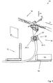
- FIG. 1 shows a gyroplane according to the invention 10 with a payload receptacle 12 in the form of a pilot seat, a rotor 14 and a support structure 16 which connects the payload receptacle 12 with the rotor 14.
- a payload receptacle 12 in the form of a pilot seat
- a rotor 14 and a support structure 16 which connects the payload receptacle 12 with the rotor 14.
- All components are summarized, which are in the flight operation of the gyrocopter 10th rotate.
- the gyrocopter 10 is driven by a motor 18, which cooperates with a not shown propeller and is mounted on a motor mount 19.
- the support structure 16 has a damping device 20, which in turn comprises a rotary joint in the form of a ball joint 22.
- the damping device also has a first damping element 24.1 and a second damping element 24.2 in the form of piezoactuators, which are arranged in Gegensan Aunt. Two other damping elements, which are also mounted in antagonist arrangement, are not shown.
- the damping elements 24 act both as actuators and as sensors which detect a torque acting on the rotary joint 22 and apply a counter-torque, so that an oscillation of the rotor 14 penetrates only damped to payload absorption.
- the gyrocopter 10 In flight, the rotor 14 performs a tumbling motion relative to the support structure 16, which is described in the coordinate system of the gyrocopter.
- the gyrocopter 10 has a vertical axis H, a longitudinal axis L and a transverse axis Q which are perpendicular to each other and relate to the position of the gyrocopter in cruising flight.
- the damping device 20 is in accordance with the embodiment FIG. 1 designed to dampen the transmission of pitching motion of the rotor to the seat 12.
- a pitching movement is understood to mean that the rotor 14 oscillates about the transverse axis Q. This corresponds to a movement of the support structure 16 in a plane E N , which is perpendicular to the transverse axis Q.
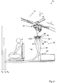
- FIG. 2 shows a further embodiment of a trolley according to the invention 10, in which the damping device 20 comprises a plurality of piezoelectric actuators 24, of which the piezoelectric actuators 24.1, 24.2 are shown.
- the piezoelectric actuators 24 are connected to a drive unit 25, by means of which they can be acted upon by an electrical voltage, so that they lengthen adjustable or shorten.
- the piezo actuators are arranged between a first support plate 26 and a second support plate 28.
- the second support plate 28 is rigidly connected to a rotor head 32, whereas the first support plate 26 is rigidly connected to a support arm 34 to which the payload receptacle 12 is attached in the form of the pilot's seat.
- the damping device 20 may detect position sensors for detecting a position of the two support plates 26 and 28 relative to each other. Position data detected by the position sensors are detected by the drive unit, whereupon the drive unit applies voltage to the piezo actuators 24 in such a way that the oscillation of the pilot seat 12, that is to say its cyclic acceleration, is reduced.
- a plurality of springs 30.1, 30.2, ... can be arranged between the first support plate 26 and the second support plate 28.
- the damping device comprises damping elements in the form of rubber-elastic elements. It can be provided that the damping elements are adjustable in their rigidity. This can be realized, for example, in that the damping elements can be prestressed via a pretensioning device, so that the damping elements can be set harder by increasing a pretensioning force.
- FIG. 3 shows an alternative embodiment in which the damping device 20 includes a pivot that is pivotable about only one axis of rotation, namely the transverse axis. This has the advantage that the rigidity of the support structure 16 with the damping device 20 is weakened by this only insignificantly.
- the damping device 20 is designed such that an amplitude A of the acceleration a (t) (t denotes the time) decreases by at least 50%, which reduces the load of the pilot.
- the damping device 20 is designed such that a natural frequency f L with respect to a plane perpendicular to the longitudinal axis L and a natural frequency f Q with respect to the plane E N perpendicular to the transverse axis Q are greater than 14 Hertz.
- FIG. 4 shows a particularly advantageous embodiment of a trolley according to the invention, in which the payload receptacle 12 is attached to a cantilevered pulpit 36.
- the pulpit 36 is attached to a fuselage-side support member 38.
- the hull-side support member 38 is connected to a rotor-side support member 40 to which the rotor head 32 is attached.
- the hull-side support element 38 and the rotor-side support element 40 are connected to one another in a damping device 20.
- FIG. 5a shows a detailed view of the damping device 20.
- the damping device 20 comprises a rubber-elastic element 42.1, which is formed as a hollow cylinder.
- the rubber-elastic element is arranged in a sleeve 44.1 which is fastened to the fuselage-side support element 38.
- FIG. 5b shows a rotated by 90 ° about the longitudinal axis view.
- the rubber-elastic element 42.1 is penetrated by a bolt 46.1, which is attached to the rotor-side support member 40.
- the damping device 20 also comprises at least one second rubber-elastic element 42.2, which is arranged in a second sleeve 44.2 and a second Bolt 46.2 is penetrated.
- the second bolt 46.2 is also connected to the rotor-side support member 40, for example, welded or screwed.
- the hull-side support element 38, the rotor-side support element 40 and the damping device are part of the support structure 16 which has a support structure longitudinal axis L T.
- the hull-side support element 38 and the rotor-side support element 48 engage with one another, so that an oscillation in the direction of the support structure longitudinal axis L T is effectively damped by the damping device 20.
- vibrations perpendicular to the support structure longitudinal axis L T are significantly less damped, so that a rigidity in these transverse directions is increased. In this way, unpleasant vibrations are damped particularly effectively for the pilot, whereas the rigidity required for the stability of the gyroplane is maintained in the transverse direction.
- FIG. 5c shows a perspective glass body view of the damping device (20).
- the FIG. 5d shows a plan view in a glass body view of the damping device according to FIG. 5c ,
- FIG. 6 shows a gyro according to the invention 10 according to a second embodiment, the damping device is not shown.
- the gyroplane has a longitudinal axis L and a transverse axis Q and includes a rotor 112 and a propeller 114 which is part of a fuselage 116.
- the hull 116 is connected to the rotor 112 via a rotor head 118.
- FIG. 7 shows the rotor head 118, which includes a roll axis 120 and a pitch axis 122.
- the rotor head 118 is tiltable relative to the hull 116 by means of a control device 124.
- the control device 124 includes a joystick 126, a roll axis actuator cylinder 128, and a pitch axis actuator cylinder 130.
- the roll axis actuator cylinder 128 is connected to a roll axis control cylinder 136 via a first hydraulic line 132 and a second hydraulic line 134.
- the roll axis actuator cylinder 128 is, as in FIG. 7 is indicated schematically connected to the joystick 126 so that a movement of the joystick 126 in the transverse direction, which is indicated by a plane pointing upwards from the plane of the arrow P1, causes the hydraulic fluid 138 in the first hydraulic line 132 as indicated by an arrow P2 indicated flows and in the second hydraulic line 134 as indicated by an arrow P3 flows.
- a piston 140 of the roll axis actuator cylinder 128 is then in FIG. 7 pressed down so that the rotor head 118 tilts around the roll axis 120.
- the roll axis actuator cylinder is attached to a first end 142 to a nozzle 144 which is disposed below the pitch axis 122. As a result, pitching of the rotor head 118 does not result in rolling of the rotor head 118.
- a lower end of the pitch axis actuator cylinder 130 is connected to a first end of a pitch axis control cylinder 148 via a third hydraulic line 146.
- a second end of the pitch axis control cylinder 148 communicates via a fourth hydraulic line 150 in communication with an upper end of the pitch axis actuator cylinder 130. If the joystick 126 is moved longitudinally as indicated by an arrow P4, this movement will move via a rod 152 to a position shown in FIG Transfer piston of the pitch axis control cylinder 148.
- hydraulic fluid 154 is moved in the hydraulic lines 146, 150 and the rotor head 118 reduces its pitch angle. That means that in FIG. 7 the rotor 112 pivots to the right about the pitch axis 122.
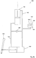
- FIG. 8a shows a schematic view of a roll axis control device 158 that is part of the control device 124.
- the roll axis control device 158 comprises, in addition to the roll axis actuator cylinder 128, the roll axis control cylinder 136 and the hydraulic lines 132, 134, a pressure holder 160.
- the pressure holder 160 has a diaphragm 162 which separates a pressure gas chamber 164 from the hydraulic fluid 138.
- the compressed gas chamber 164 is filled with a pressurized gas, such as nitrogen.
- the gas pressure may be, for example, above 130 bar.
- the first hydraulic line 132 and the second hydraulic line 134 can be connected to one another via a connecting valve 166 and can be separated from one another. If the connecting valve 166 is opened, the control stick 126 can be moved without this leading to a movement of the piston 140 of the roll axis actuator cylinder 130.
- FIG. 8b 10 shows a pitch axis control device 168 with the pitch axis control cylinder 148, the pitch axis actuator cylinder 130 and the hydraulic lines 146, 150.
- the remaining components have the same designations as the corresponding components of the roll axis control device 158 (FIG. FIG. 8a ) with a dash. It can be provided that both control systems are connected to each other via a not shown connecting valve, so that a pressure holder 160 is sufficient.
Landscapes
- Engineering & Computer Science (AREA)
- Mechanical Engineering (AREA)
- Aviation & Aerospace Engineering (AREA)
- Vibration Prevention Devices (AREA)
Description
- Die Erfindung betrifft einen Tragschrauber mit einer Nutzlastaufnahme in Form eines Sitzes, einem Rotor und einer den Rotor mit der Nutzlastaufnahme verbindenden Tragstruktur.
- Derartige Tragschrauber werden beispielsweise als Luftsportgerät verwendet. Nachteilig an bekannten Tragschraubern ist, dass insbesondere längere Flüge bei den Piloten zu Ermüdungserscheinungen führen können.
- Der Erfindung liegt die Aufgabe zugrunde, einen Tragschrauber anzugeben, der besonders ermüdungsfrei geflogen werden kann.
- Aus der
US 4,819,182 und derUS 2008/0279685 A1 sind Systeme zum aktiven Einwirken auf Stellelemente bekannt, mittels derer die Vibrationen in einem Hubschrauber vermindert werden können. Derartige Systeme sind in einem Tragschrauber prinzipbedingt oder wegen des hohen technischen Aufwands nicht einsetzbar. - Aus der
US 6,231,013 B1 ist bekannt, die Kontur eines Rotorflügels beim Betrieb zu ändern, um so Schwingungen zu reduzieren. - Aus der
GB 2 043 574 A - Aus der
US 4,912,999 ist ebenfalls ein Rotorkopf für einen Helikopter bekannt, der mehrere, gegeneinander durch Dämpfer abgetrennte Achsen aufweist. Auch dieses System ist aufwändig konstruiert. - Aus der
DE 10 2004 058 301 A1 ist ein aktiver Dämpfer für einen Hubschrauber bekannt, bei dem die Getriebe-Rotor-Einheit die primäre Vibrationsquelle darstellt. Ein derartiges System ist wegen seiner Komplexität für Tragschrauber in der Regel ungeeignet. - Aus der
GB 2 105 668 A - Die Erfindung löst das Problem durch einen Tragschrauber gemäß Anspruch 1.
- Vorteilhaft an der Erfindung ist, dass das Vorsehen der Dämpfvorrichtung vom Rotor kommende Schwingungen unterdrückt, was zu einem ermüdungsärmeren Fliegen führt. Es hat sich nämlich herausgestellt, dass vom Rotor kommende Vibrationen maßgeblich zur Ermüdung des Piloten beitragen.
- Vorteilhaft ist zudem, dass der erfindungsgemäße Tragschrauber besonders gelenkschonend geflogen werden kann. Insbesondere die Bandscheiben des Piloten werden gegenüber bekannten Tragschraubern entlastet, da sie weniger stark durch Vibrationen belastet werden.
- Es ist ein weiterer Vorteil, dass das Dämpfen der Vibrationen die komplette Kanzel betreffen kann. Anders als wenn beispielsweise nur die Nutzlastaufnahme des Tragschraubers in Form eines Pilotensitzes gedämpft wird, entsteht keine Relativbewegung zwischen dem Steuerknüppel des Tragschraubers und dem Pilotensitz.
- Der Erfindung liegt die Erkenntnis zugrunde, dass es möglich ist, die Steifigkeit der Tragstruktur zwischen Nutzlastaufnahme und Rotor zu vermindern, ohne die Flugstabilität des Tragschraubers zu beeinflussen. Das ist insofern überraschend, als dass eine verminderte Steifigkeit der Tragstruktur zu einer größeren Bewegung des Rotors führt. Dies wiederum bewirkt Änderungen am aerodynamischen Verhalten des Rotors, weshalb bislang eine besonders hohe Steifigkeit der Tragstruktur angestrebt wird.
- Im Rahmen der vorliegenden Beschreibung wird unter der Nutzlastaufnahme insbesondere ein Pilotensitz für einen Piloten verstanden. Wenn es sich bei dem Tragschrauber um ein Luftsportgerät handelt, so kann die Nutzlastaufnahme einen, zwei oder drei Pilotensitze umfassen. Grundsätzlich ist die Erfindung auch für Tragschrauber im Modellformat geeignet. In diesem Fall kann die Nutzlastaufnahme beispielsweise eine Halterung für eine Kamera oder einen anderen Sensor sein. Besonders gut geeignet ist die Erfindung aber für Tragschrauber, die zum Personentransport ausgebildet sind.
- Unter einer Tragstruktur wird insbesondere die Gesamtheit aller Elemente verstanden, die den Rotor mit der Nutzlastaufnahme so verbinden, dass die Last der Nutzlastaufnahme aufgenommen wird. Es kann sich dabei beispielsweise um ein Gestänge, ein einzelnes Tragrohr, ein System aus Tragrohr und Gestänge, oder Ähnliches handeln.
- Der Tragschrauber umfasst bevorzugt einen Rotorkopf, der nicht Teil der Tragstruktur ist und zwischen der Tragstruktur, die auch als Rumpf bezeichnet werden kann, und dem Rotor angeordnet ist. Der Rotorkopf umfasst diejenigen Komponenten, die zum Betätigen des Rotors dienen. Vorzugsweise ist die Dämpfvorrichtung des Rumpfes.
- Unter dem Merkmal, dass die Tragstruktur eine Dämpfvorrichtung zum Dämpfen von vom Rotor ausgehenden Schwingungen aufweist, ist insbesondere zu verstehen, dass die Tragstruktur einen ersten Abschnitt mit einer ersten Steifigkeit, einen zweiten Abschnitt mit einer zweiten Steifigkeit und einen dritten Abschnitt mit einer dritten Steifigkeit aufweist, wobei der zweite Abschnitt zwischen dem ersten und dem dritten Abschnitt angeordnet ist und eine Steifigkeit aufweist, die kleiner ist als die des ersten Abschnitts und die des dritten Abschnitts. Dabei ist die Steifigkeit des zweiten Abschnitts, insbesondere kleiner als die Hälfte der Steifigkeit des ersten Abschnitts und des dritten Abschnitts. Der zweite Abschnitt ist zudem so ausgebildet, dass eine Relativbewegung von erstem Abschnitt und drittem Abschnitt aktiv und/oder passiv gedämpft wird.
- Unter dem Merkmal, dass die Tragstruktur einen ersten Abschnitt mit einer ersten Steifigkeit besitzt, wird dann insbesondere verstanden, dass der erste Abschnitt bezüglich einer Schwingung in einer ersten Ebene die erste Steifigkeit hat, also der Widerstand, den die Tragstruktur einer Verformung in dieser Ebene entgegensetzt. Im Kraftfluss vom Rotor zur Nutzlastaufnahme folgen dann ein zweiter Abschnitt mit einer zweiten, kleineren Steifigkeit und ein dritter Abschnitt mit einer dritten Steifigkeit. Diese Steifigkeiten beziehen sich ebenfalls auf eine Auslenkung in der gleichen Ebene.
- Unter der Dämpfvorrichtung für vom Rotor ausgehenden Schwingungen wird insbesondere jede Vorrichtung verstanden, die so ausgelegt ist, dass bei Reisegeschwindigkeit, das heißt bei der höchsten dauerhaft möglichen Geschwindigkeit, die vom Rotor ausgehenden Schwingungen in zumindest einer Schwingungsebene um mehr als 80 % gemindert werden. Das bedeutet, dass die Amplitude der Schwingung an der Nutzlastaufnahme nur höchstens 0,2-fach so groß ist wie ohne die Dämpfvorrichtung.
- Unter einer Dämpfvorrichtung ist eine Vorrichtung zu verstehen, die eine vom Rotor ausgehende Schwingung dadurch vermindert, dass der Schwingung eine innewohnende Energie zumindest teilweise in Wärme umgewandelt wird.
- Gemäß einer bevorzugten Ausführungsform hat der Tragschrauber beim Betrieb einen Massenschwerpunkt, wobei die Dämpfvorrichtung auf einer Höhe zwischen einer Massenschwerpunkt-Höhe des Massenschwerpunkts und einer Rotorhöhe des Rotors angeordnet ist. In anderen Worten ist die Dämpfvorrichtung benachbart zum Rotor angeordnet. Das führt dazu, dass vom Rotor ausgehende Schwingungen besonders effektiv gemindert werden können. Der Massenschwerpunkt bezieht sich auf den Tragschrauber mit Nutzlast, also beispielsweise mit Pilot.
- Günstig ist es, wenn die Dämpfvorrichtung so ausgebildet ist, dass sie eine Schwingung des Rotors um eine Querachse des Tragschraubers dämpft. Eine derartige Schwingung führt zu einer Auf- und Abschwingung am Pilotensitz, was besonders unerwünscht ist. Es kann vorgesehen sein, dass die Dämpfvorrichtung für Schwingungen um die Längsachse im Wesentlichen keine Dämpfwirkung hat. Derartige Schwingungen führen zu einer Drehschwingung des Pilotensitzes um einen Körperschwerpunkt des Piloten, was als wenig belastend empfunden wird. Zudem führt die Steifigkeit bezüglich einer Deformation in der Ebene senkrecht zur Längsachse zu geringen Relativbewegungen von Rotor zur Tragstruktur.
- Gemäß einer bevorzugten Ausführungsform umfasst die Dämpfvorrichtung ein Gelenk, insbesondere ein Drehgelenk. Hierunter ist insbesondere ein Kugelgelenk, ein Kreuzgelenk oder ein Kadergelenk zu verstehen. Möglich ist aber auch ein Gelenk, das nur einen Schwenkfreiheitsgrad hat. In diesem Fall ist die Schwenkachse vorzugsweise die Querachse des Tragschraubers.
- Bevorzugt umfasst die Dämpfvorrichtung zumindest ein aktives Dämpfelement. Unter einem aktiven Dämpfelement ist insbesondere ein Aktor zu verstehen, der über eine Energiezuführung Kräfte auf zwei Teile des Gelenks ausüben kann, die so gewählt sind, dass vom Rotor ausgehende Schwingungen die Nutzlastaufnahme nur abgeschwächt erreichen. Bei dem aktiven Dämpfelement kann es sich beispielsweise um einen Piezoaktor oder einen magnetostriktiven Aktor handeln. Das aktive Dämpfelement kann zudem ein aktiv einstellbares Dämpfelement sein, bei dem die Dämpfwirkung, beispielsweise elektrisch durch Anlegen einer Spannung oder eines Stroms, eingestellt werden kann.
- Alternativ oder additiv umfasst die Dämpfvorrichtung zumindest ein passives Dämpfelement. Hierunter ist insbesondere zu verstehen, dass ein Bauteil vorhanden ist, das eine elastische Verformung zu einem hohen Anteil in Wärme umsetzt. Es kann sich beispielsweise um ein gummielastisches Element handeln. Alternativ oder additiv ist ein fluidhaltiger Dämpfer einsetzbar, beispielsweise ein Hydraulik- oder ein Pneumatikdämpfer. Bei derartigen Fluiddämpfern führt eine Bewegung zwischen zwei Aufhängepunkten des Fluiddämpfers dazu, dass ein Fluid von einer Kammer des Fluiddämpfers in eine andere bewegt wird und dabei durch eine Verengung strömt, so dass das Fluid beim Durchströmen Energie verliert. Das Fluid kann eine Flüssigkeit oder ein Gas sein.
- Bevorzugt ist das Dämpfelement in seiner Dämpfung einstellbar. Wenn es sich um ein aktives Dämpfelement handelt, kann die Dämpfung des Dämpfelements direkt eingestellt werden.
- Gemäß einer bevorzugten Ausführungsform weist die Dämpfvorrichtung eine einstellbare Federkonstante auf. Beispielsweise besitzt die Dämpfvorrichtung ein elastisches Element, das vorspannbar ist. Hierzu kann beispielsweise ein Dämpfelement eine nicht lineare Abhängigkeit der Rückstellkraft von der Auslenkung aufweisen. Das ist beispielsweise bei gummielastischen Dämpfelementen oder McKibben-Muskeln der Fall.
- Vorzugsweise ist die Dämpfvorrichtung so ausgebildet, dass eine erste Eigenfrequenz der Tragstruktur mindestens 14 Hertz beträgt. Es hat sich gezeigt, dass so eine hinreichend hohe Sicherheit beim Betrieb des Tragschraubers erreicht werden kann. Insbesondere ist die Dämpfvorrichtung so ausgebildet, dass die Eigenfrequenz der Tragstruktur für eine Schwingung in einer Ebene senkrecht zur Längsachse des Tragschraubers mindestens 14 Hertz beträgt. Es ist möglich, dass die Dämpfvorrichtung so ausgebildet, dass die Eigenfrequenz beispielsweise für eine Schwingung senkrecht zur Querachse unter 14 Hertz liegt.
- Bevorzugt ist die Dämpfvorrichtung zum Dämpfen von vom Rotor ausgehenden Schwingungen ausgebildet, die eine Bewegung der Nutzlastaufnahme mit einer vertikalen Bewegungskomponente bewirken. Hierunter zählen Schwingungen um die Querachse. Die Drehbewegung des Rotors führt zu einer Vielzahl von sich überlagernden Kräften und Drehmomenten. Besonders störend sind solche Kräfte bzw. Drehmomente, die zu einer Auf- und Ab-Bewegung der Nutzlastaufnahme führen. Dies ist nämlich für den Piloten besonders belastend. Wenn die Tragstruktur einen gebogenen Verlauf hat, so ist die Dämpfvorrichtung bevorzugt zum Dämpfen von Bewegungen des Rotors um eine Nickachse ausgebildet.
- Gemäß einer bevorzugten Ausführungsform besitzt die Tragstruktur ein rotorseitiges Tragelement und ein rumpfseitiges Tragelement und die Dämpfvorrichtung weist ein gummielastisches Element und einen das gummielastische Element durchgreifenden Bolzen auf, wobei ein Kraftfluss von dem rotorseitigen Tragelement in das rumpfseitige Tragelement durch den Bolzen und das gummielastische Element verläuft. Beispielsweise ist das gummielastische Element hohlzylinderförmig und ist in einer Hülse aufgenommen, die an dem Tragelement befestigt ist, das mit dem Bolzen fest verbunden ist. Im Betrieb verläuft der Kraftfluss vom Tragelement über den Bolzen, das gummielastische Element und die Hülse in das andere Tragelement. Dieser Aufbau ist besonders einfach und zudem sehr sicher. Versagt nämlich das gummielastische Element, so verläuft der Kraftfluss vom Bolzen direkt in die Hülse, die Stabilität des Tragschraubers ist aber gewahrt.
- Besonders günstig ist es, wenn das Tragelement, an dem der Bolzen befestigt ist, das Tragelement, an dem die Hülse befestigt ist, zumindest abschnittsweise umgreift. So wird eine Schwingung in Längsrichtung der Tragelemente besonders wirksam gedämpft. Schwingungen der beiden Tragelemente quer zueinander hingegen werden über den direkten Kontakt der beiden Tragelemente übertragen. So wird eine hohe Stabilität in Querrichtung erhalten.
- Gemäß einer bevorzugten Ausführungsform hat der Tragschrauber einen Rumpf und einen relativ zum Rumpf kippbaren Rotorkopf sowie eine hydraulische Steuervorrichtung zum Kippen des Rotorkopfs relativ zum Rumpf. Ein derartiger Tragschrauber kann auch eine Dämpfvorrichtung aufweisen, das ist aber nicht notwendig.
- Bekannt sind Tragschrauber, bei denen der Rotorkopf mittels Steuerstangen mit einem Steuerknüppel verbunden ist. Wird der Steuerknüppel bewegt, so wird diese Bewegung mittels der Steuerstangen auf den Rotorkopf übertragen und dadurch gekippt. Je nach dem, ob der Rotorkopf im Flug um eine Nickachse oder eine Rollachse gekippt wird, beschleunigt der Tragschrauber nach vorne oder zur Seite. Nachteilig an bekannten Tragschraubern ist, dass es nicht möglich ist, den Rotorkopf so vom Rumpf zu entkoppeln, dass ein Eintrag von Schwingungen des Rotorkopfs auf den Rumpf vermindert wird, ohne dass aufgrund der Entkopplung der Steuerknüppel zu vibrieren anfängt.
- Vorteilhaft an diesem Tragschrauber ist, dass eine Schwingung des Rotorkopfs relativ zum Rumpf des Tragschraubers über die hydraulische Steuervorrichtung übertragen wird. Die hydraulische Steuervorrichtung hat eine höhere Dämpfung als eine mechanische Verbindung, so dass der Steuerknüppel besonders ruhig ist. Das erhöht den Komfort beim Fliegen. Des Weiteren führt die verringerte Vibration zu weniger Ermüdung beim Piloten und damit zu mehr Sicherheit.
- Vorteilhaft ist zudem, dass eine hydraulische Steuervorrichtung einfach mit einer Untersetzung realisiert werden kann. Das wiederum hat den Vorteil, dass der Tragschrauber weniger empfindlich auf kleine Bewegungen des Steuerknüppels reagiert.
- Vorteilhaft ist zudem, dass die hydraulische Steuervorrichtung so ausgebildet sein kann, dass Hydraulikleitungen an aerodynamisch günstiger Stelle angebracht sind, beispielsweise im Windschatten des Rumpfs. Das senkt den Luftwiderstand des Tragschraubers und damit dessen Verbrauch.
- Es wird unter dem Rotorkopf diejenige Einheit des Tragschraubers verstanden, die den Rotor mit dem starren Rumpf gelenkig verbindet. In anderen Worten ist der Rotorkopf dasjenige Bauteil, an dem der Rotor befestigt ist und mittels dem der Rotor relativ zum Rumpf verschwenkbar ist.
- Unter der hydraulischen Steuervorrichtung wird insbesondere jede Steuervorrichtung verstanden, bei der eine Bewegung des Steuerknüppels in zumindest einer Richtung mittels einer Hydraulikflüssigkeit auf den Rotorkopf übertragen wird. Es ist dabei möglich, nicht aber notwendig, dass die Bewegungen des Steuerknüppels sowohl in Längsrichtung als auch in Querrichtung über die Hydraulikflüssigkeiten übertragen werden. So ist durchaus denkbar, dass eine Bewegung des Steuerknüppels in Querrichtung über eine Hydraulikflüssigkeit übertragen wird, wohingegen eine Bewegung in Längsrichtung mechanisch übertragen wird. Eine Bewegung des Steuerknüppels in Längsrichtung bezeichnet dabei eine Bewegung vom Piloten weg oder auf ihn zu, was einer Bewegung in Längsrichtung des Tragschraubers entpricht.
- Gemäß einer bevorzugten Ausführungsform besitzt die Steuervorrichtung einen Steuerknüppel, einen Steuerzylinder, der mit dem Steuerknüppel verbunden ist, und einen Aktorzylinder, der mit dem Rotorkopf verbunden ist, wobei der Aktorzylinder so mit dem Steuerzylinder verbunden ist, dass eine Bewegung des Steuerknüppels zu einem Kippen des Rotorkopfs relativ zum Rumpf führt.
- Es ist möglich, mehr als einen Steuerzylinder vorzusehen. Beispielsweise sind zwei Steuerzylinder und zwei Aktorzylinder jeweils in Gegenspieleranordnung ange- ordnet. Wird der Steuerknüppel in eine Richtung bewegt, so werden die Kolben der beiden Steuerzylinder in entgegengesetzte Richtungen bewegt. Daraus folgend werden auch die Kolben der beiden Aktorzylinder in entgegengesetzte Richtungen bewegt. Weil die Kolben der Aktorzylinder an entgegengesetzten Stellen am Rotorkopf angreifen, kippen sie ihn in die gleiche Richtung. Die jeweiligen Hydrauliksysteme aus Steuer- und Aktorzylinder sowie zugehörigen Hydraulikleitungen sind voneinander unabhängig, so dass eine Redundanz erzielt wird. Aus Gewichtsgründen ist es jedoch günstig, wenn nur ein Aktorzylinder und ein Steuerzylinder zum Kippen des Rotorkopfs um eine vorgegebene Achse vorgesehen sind. Vorteilhaft ist, wie weiter unten beschrieben wird, wenn zumindest zwei Teil-Steuervorrichfungen, nämlich eine Rollachsen-Steuervorrichtung und eine Nickachsen-Steuervorrichtung, mit jeweiligem Aktor- und Steuerzylinder vorhanden sind, die auf unterschiedliche Achsen des Tragschraubers wirken, nämlich auf eine Rollachse und eine Nickachse.
- Bevorzugt weist die Steuervorrichtung einen Druckhalter auf. Unter einem Druckhalter wird eine Vorrichtung verstanden, die so ausgebildet ist, dass ein Hydraulikdruck, unter dem die Hydraulikflüssigkeit steht, oberhalb eines Mindest-Hydraulikdrucks gehalten wird. Hierdurch wird verhindert, dass sich eine etwaig vorhandene Gasblase in der Hydraulikflüssigkeit ausdehnt, wenn sich eine mit Hydraulikflüssigkeit gefüllte Komponente thermisch ausdehnt. Eine derartige Gasblase würde das Ansprechverhalten der Steuervorrichtung negativ beeinflussen und zu Spiel führen. Durch den Druckhalter wird ein stets hohes gutes Ansprechverhalten der Steuervorrichtung gewährleistet.
- Besonders vorteilhaft ist, wenn der erste Druckhalter eine mit unter Gasdruck stehendem Druckgas gefüllte erste Druckgaskammer, eine mit Hydraulikflüssigkeit gefüllte erste Hydraulikfluidkammer und eine Membran aufweist, die die erste Druckgaskammer von der ersten Hydraulikfluidkammer so trennt, dass der Gasdruck auf die Hydraulikflüssigkeit übertragen wird. Ein derartiger Druckhalter lässt sich besonders einfach herstellen, sicher betreiben und gut warten.
- Bevorzugt weist die Steuervorrichtung eine erste Hydraulikleitung, die ein erstes Ende des Steuerzylinders mit einem ersten Ende des Aktorzylinders verbindet, eine zweite Hydraulikleitung, die ein zweites Ende des Steuerzylinders mit einem zweiten Ende des Aktorzylinders verbindet, und ein Verbindungsventil zum Verbinden und Trennen von erster Hydraulikleitung und zweiter Hydraulikleitung auf. Hierdurch ist der Steuerknüppel justierbar. Zum Justieren des Steuerknüppels wird zunächst der Rotorkopf in seine Neutrallage gebracht, dass heißt in die Lage, die sich bei einer Fluggeschwindigkeit von 120 kmlh relativ zur umgebenden Luft selbsttätig einstellt. Danach wird bei geöffnetem Verbindungsventil der Steuerknüppel in die Lage gebracht, die der Steuerknüppel bei Neutrallage des Rotorkopfs einnehmen soll. Anschließend wird das Verbindungsventil geschlossen. So ist es möglich, individuelle Einstellungen des Steuerknüppels vorzunehmen.
- Vorzugsweise ist das Verbindungsventil gegen unbeabsichtigtes Verbinden geschützt. Beispielsweise rastet das Verbindungsventil in der Stellung ein, in der die beiden Hydraulikleitungen voneinander getrennt sind. So wird verhindert, dass das Verbindungsventil im Flug die beiden Hydraulikleitungen verbindet, wodurch steuern unmöglich würde.
- Gemäß einer bevorzugten Ausführungsform ist die Steuervorrichtung so ausgebildet, dass eine Druckschwankung im Aktorzylinder mit 18 Hertz zu einer Druckschwankung im Steuerzylinder führt, deren Amplitude um mindestens 70% kleiner ist. Das heißt, dass beispielsweise eine sinusförmige Schwingung des Rotorkopfs relativ zum Rumpf mit 18 Hertz zu einer Druckschwankung im Aktorzylinder führt, die ebenfalls sinusförmig ist und eine bestimmte Amplitude hat. Die Druckamplitude, die im Steuerzylinder (der mit dem Steuerknüppel verbunden ist) anliegt, beträgt dann höchstens das 0,3-fache der Amplitude im Aktorzylinder. Es sind sogar deutlich höhere Dämpfungen möglich, beispielsweise auf unter 10%.
- Das wird besonders einfach dadurch erreicht, dass ein erster Hydraulikleitungs-Querschnitt der ersten Hydraulikleitung und/oder ein zweiter Hydraulikleitungs-Querschnitt der zweiten Hydraulikleitung so klein gewählt, dass die genannte Dämpfung erreicht wird.
- Gemäß einer bevorzugten Ausführungsform ist ein Steuerzylinderquerschnitt des Steuerzylinders höchstens so groß wie ein Aktorzylinderquerschnitt des Aktorzylinders. Das führt zu einer Untersetzung, so dass der Tragschrauber weniger empfindlich auf eine Bewegung des Steuerknüppels reagiert.
- Bevorzugt ist der Aktorzylinder so mit dem Steuerzylinder und dem Rotorkopf verbunden ist, dass eine Bewegung des Steuerknüppels in Querrichtung zu einem Kippen des Rotorkopfs um eine Rollachse des Tragschraubers führt. Aufgrund ihrer Funktion können dann der Steuerzylinder als Rollachsen-Steuerzylinder und der Aktorzylinder als Rollachsen-Aktorzylinder bezeichnet werden. Beide sind zusammen mit den zugehörigen Hydraulikleitungen Teil einer Rollachsen-Steuervorrichtung, die ihrerseits Teil der hydraulischen Steuervorrichtung ist.
- Alternativ ist der Aktorzylinder so mit dem Steuerzylinder und dem Rotorkopf verbunden ist, dass eine Bewegung des Steuerknüppels in Querrichtung zu einem Kippen des Rotorkopfs um eine Nickachse des Tragschraubers führt. Aufgrund ihrer Funktion können dann der Steuerzylinder als Nickachsen-Steuerzylinder und der Aktorzylinder als Nickachsen-Aktorzylinder bezeichnet werden. Beide sind zusammen mit den zugehörigen Hydraulikleitungen Teil einer Nickachsen-Steuervorrichtung, die ihrerseits Teil der hydraulischen Steuervorrichtung ist.
- Eine vollständig hydraulische Steuervorrichtung wird erhalten, wenn die Steuervorrichtung (a) eine Rollachsen-Steuervorrichtung umfasst, die einen Rollachsen-Aktorzylinder, der mit dem Rotorkopf verbunden ist, und einen Rollachsen-Steuerzylinder, der mit dem Steuerknüppel so verbunden ist, dass eine Bewegung des Steuerknüppels in Querrichtung zu einem Kippen des Rotorkopfs um eine Rollachse des Tragschraubers führt, aufweist und (b) Nickachsen-Steuervorrichtung umfasst, die einen Nickachsen-Aktorzylinder, der mit dem Rotorkopf verbunden ist, und einen Nickachsen-Steuerzylinder, der mit dem Steuerknüppel so verbunden ist, dass eine Bewegung des Steuerknüppels in Längsrichtung zu einem Kippen des Rotorkopfs um eine Nickachse des Tragschraubers führt, aufweist.
- Besonders vorteilhaft ist es, wenn der Rotorkopf so getrimmt ist, dass dann, wenn zumindest eine der Hydraulikleitungen druckfrei ist, der Tragschrauber in einer stabilen Fluglage stabilisiert ist. Das bedeutet in anderen Worten, dass dann, wenn eine oder alle Hydraulikleitungen aufgrund beispielsweise eines Unfalls nicht mehr in der Lage sind, einen Druck vom jeweiligen Steuerzylinder auf den jeweiligen Aktorzylinder zu übertragen, der Rotor relativ zum Rumpf eine solche Lage einnimmt, dass der Tragschrauber durch reduzieren einer Motorleistung eines Motors gelandet werden kann.
- Im Folgenden wird die Erfindung anhand exemplarischer Ausführungsbeispiele und mit Bezug auf die beigefügten Zeichnungen näher erläutert. Dabei zeigt
- Figur 1
- eine schematische Ansicht einer ersten Ausführungsform der Erfindung,
- Figur 2
- eine schematische Ansicht einer zweiten Ausführungsform der Erfindung,
- Figur 3
- eine Ansicht einer dritten Ausführungsform der Erfindung und
- Figur 4
- eine schematische Ansicht einer zweiten Ausführungsform eines erfindungsgemäßen Tragschraubers. Die
- Figuren 5a, 5b,5c und 5d
- zeigen Detailansichten der Dämpfvorrichtung des Tragschraubers nach
Figur 4 . - Figur 6
- zeigt eine Seitenansicht eines Tragschraubers gemäß einer zweiten Ausführungsform der Erfindung,
- Figur 7
- einen Rotorkopf eines erfindungsgemäßen Tragschraubers gemäß einer zweiten Ausführungsform und
- Figur 8a
- eine schematische Ansicht einer Rollachsen-Steuervorrichtung der hydraulischen Steuervorrichtung des Tragschraubers gemäß
Figur 2 . - Figur 8b
- zeigt eine Nickachsen-Steuervorrichtung der hydraulischen Steuervorrichtung des Tragschraubers gemäß
Figur 2 . -
Figur 1 zeigt einen erfindungsgemäßen Tragschrauber 10 mit einer Nutzlastaufnahme 12 in Form eines Pilotensitzes, einem Rotor 14 und einer Tragstruktur 16, die die Nutzlastaufnahme 12 mit dem Rotor 14 verbindet. Unter dem Rotor 14 werden alle Komponenten zusammengefasst, die sich beim Flugbetrieb des Tragschraubers 10 drehen. Der Tragschrauber 10 wird von einem Motor 18 angetrieben, der mit einem nicht eingezeichneten Propeller zusammenwirkt und auf einer Motoraufnahme 19 montiert ist. - Die Tragstruktur 16 besitzt eine Dämpfvorrichtung 20, die ihrerseits ein Drehgelenk in Form eines Kugelgelenks 22 umfasst. Die Dämpfvorrichtung besitzt zudem ein erstes Dämpfelement 24.1 und ein zweites Dämpfelement 24.2 in Form von Piezoaktoren, die in Gegenspieleranordnung angeordnet sind. Zwei weitere Dämpfelemente, die ebenfalls in Gegenspieleranordnung angebracht sind, sind nicht eingezeichnet. Die Dämpfelemente 24 wirken sowohl als Aktoren als auch als Sensoren, die ein auf das Drehgelenk 22 wirkendes Drehmoment erfassen und ein GegenDrehmoment aufbringen, so dass eine Schwingung des Rotors 14 nur gedämpft zur Nutzlastaufnahme durchdringt.
- Im Flug führt der Rotor 14 relativ zur Tragstruktur 16 eine Taumelbewegung aus, die im Koordinatensystem des Tragschraubers beschrieben wird. Der Tragschrauber 10 hat eine Hochachse H, eine Längsachse L und eine Querachse Q aufweist, die jeweils senkrecht aufeinander stehen und sich auf die Position des Tragschraubers im Reiseflug beziehen.
- Die Dämpfvorrichtung 20 ist bei der Ausführungsform gemäß
Figur 1 dazu ausgelegt, um die Übertragung einer Nickbewegung des Rotors auf den Sitz 12 zu dämpfen. Unter einer Nickbewegung ist zu verstehen, dass der Rotor 14 um die Querachse Q schwingt. Das entspricht einer Bewegung der Tragstruktur 16 in einer Ebene EN, die senkrecht zur Querachse Q verläuft. - Es ist möglich, weitere Dämpfelemente vorzusehen, so dass auch eine Übertragung einer Schwingung des Rotors 14 um die Längsachse L auf die Tragstruktur 16 gedämpft wird. So wird eine Rollbewegung der Tragstruktur 16 gedämpft.
-
Figur 2 zeigt eine weitere Ausführungsform eines erfindungsgemäßen Tragschraubers 10, bei dem die Dämpfvorrichtung 20 mehrere Piezoaktoren 24 umfasst, von denen die Piezoaktoren 24.1, 24.2 eingezeichnet sind. Die Piezoaktoren 24 sind mit einer Ansteuereinheit 25 verbunden, mittels der sie mit einer elektrischen Spannung beaufschlagt werden können, so dass sie sich einstellbar längen oder verkürzen. - Die Piezoaktoren sind zwischen einer ersten Tragplatte 26 und einer zweiten Tragplatte 28 angeordnet. Die zweite Tragplatte 28 ist starr mit einem Rotorkopf 32 verbunden, wohingegen die erste Tragplatte 26 starr mit einem Tragarm 34 verbunden ist, an dem auch die Nutzlastaufnahme 12 in Form des Pilotensitzes befestigt ist.
- Die Dämpfvorrichtung 20 kann Positionssensoren zum Erfassen einer Lage der beiden Tragplatten 26 und 28 relativ zueinander erfassen. Von den Positionssensoren erfasste Lagedaten werden von der Ansteuereinheit erfasst, woraufhin die Ansteuereinheit die Piezoaktoren 24 so mit Spannung beaufschlagt, dass die Schwingung des Pilotensitzes 12, also dessen zyklische Beschleunigung, vermindert wird. Zwischen der ersten Tragplatte 26 und der zweiten Tragplatte 28 können zudem mehrere Federn 30.1, 30.2, ... angeordnet sein.
- Gemäß einer alternativen Ausführungsform umfasst die Dämpfvorrichtung Dämpfelemente in Form von gummielastischen Elementen. Es kann vorgesehen sein, dass die Dämpfelemente in ihrer Steifigkeit einstellbar sind. Das kann beispielsweise dadurch realisiert sein, dass die Dämpfelemente über eine Vorspannvorrichtung vorspannbar sind, so dass durch Erhöhen einer Vorspannkraft die Dämpfelement härter eingestellt werden können.
-
Figur 3 zeigt eine alternative Ausführungsform, bei der die Dämpfvorrichtung 20 ein Drehgelenk umfasst, dass nur um eine Drehachse, nämlich die Querachse, schwenkbar ist. Das hat den Vorteil, dass die Steifigkeit der Tragstruktur 16 mit der Dämpfvorrichtung 20 durch diese nur unwesentlich geschwächt wird. - Weil der Rotor 14 im Flug eine Nickbewegung um die Querachse Q macht, bewegt sich der Pilotensitz 12 mit einer vertikalen Bewegungskomponente, das heißt mit einer periodischen Beschleunigung a auf und ab. Die Dämpfvorrichtung 20 ist so ausgebildet, dass eine Amplitude A der Beschleunigung a(t) (t bezeichnet die Zeit) um mindestens 50% abnimmt, was die Belastung des Piloten verringert.
- Die Dämpfvorrichtung 20 ist so ausgebildet, dass eine Eigenfrequenz fL bezüglich einer Ebene senkrecht zur Längsachse L und eine Eigenfrequenz fQ bezüglich der Ebene EN senkrecht zur Querachse Q größer sind als 14 Hertz.
-
Figur 4 zeigt eine besonders vorteilhafte Ausführungsform eines erfindungsgemäßen Tragschraubers, bei dem die Nutzlastaufnahme 12 an einer frei tragenden Kanzel 36 befestigt ist. Die Kanzel 36 ist an einem rumpfseitigen Tragelement 38 befestigt. Das rumpfseitige Tragelement 38 ist mit einem rotorseitigen Tragelement 40 verbunden, an dem der Rotorkopf 32 angebracht ist. - Das rumpfseitige Tragelement 38 und das rotorseitige Tragelement 40 sind in einer Dämpfvorrichtung 20 miteinander verbunden.
-
Figur 5a zeigt eine Detailansicht der Dämpfvorrichtung 20. Die Dämpfvorrichtung 20 umfasst ein gummielastisches Element 42.1, das hohlzylinderförmig ausgebildet ist. Das gummielastische Element ist in einer Hülse 44.1 angeordnet, die an dem rumpfseitigen Tragelement 38 befestigt ist. -
Figur 5b zeigt eine um 90° um die Längsachse gedrehte Ansicht. - Das gummielastische Element 42.1 wird von einem Bolzen 46.1 durchgriffen, der am rotorseitigen Tragelement 40 angebracht ist.
- Die Dämpfvorrichtung 20 umfasst zudem zumindest ein zweites gummielastisches Element 42.2, das in einer zweiten Hülse 44.2 angeordnet ist und von einem zweiten Bolzen 46.2 durchgriffen ist. Der zweite Bolzen 46.2 ist auch mit dem rotorseitigen Tragelement 40 verbunden, beispielsweise verschweißt oder verschraubt.
- Das rumpfseitige Tragelement 38, das rotorseitige Tragelement 40 und die Dämpfvorrichtung sind Teil der Tragstruktur 16, die eine Tragstruktur-Längsachse LT hat. Das rumpfseitige Tragelement 38 und das rotorseitige Tragelement 48 greifen ineinander, so dass eine Schwingung in Richtung der Tragstruktur-Längsachse LT durch die Dämpfvorrichtung 20 effektiv gedämpft wird. Hingegen werden Schwingungen senkrecht zur Tragstruktur-Längsachse LT deutlich weniger gedämpft, so dass eine Steifigkeit in diesen Querrichtungen erhöht ist. Auf diese Weise werden für den Piloten unangenehme Schwingungen besonders effektiv gedämpft, wohingegen die für die Stabilität des Tragschraubers notwendige Steifigkeit in Querrichtung erhalten bleibt.
-
Figur 5c zeigt eine perspektivische Glaskörper-Ansicht der Dämpfvorrichtung (20). DieFigur 5d zeigt eine Draufsicht in einer Glaskörper-Ansicht der Dämpfungsvorrichtung gemäßFigur 5c . -
Figur 6 zeigt einen erfindungsgemäßen Tragschrauber 10 gemäß einer zweiten Ausführungsform, dessen Dämpfvorrichtung nicht eingezeichnet ist. Der Tragschrauber hat eine Längsachse L und eine Querachse Q und umfasst einen Rotor 112 und einen Propeller 114, der Teil eines Rumpfes 116 ist. Der Rumpf 116 ist über einen Rotorkopf 118 mit dem Rotor 112 verbunden. -
Figur 7 zeigt den Rotorkopf 118, der eine Rollachse 120 und eine Nickachse 122 umfasst. Der Rotorkopf 118 ist relativ zum Rumpf 116 mittels einer Steuervorrichtung 124 kippbar. Die Steuervorrichtung 124 umfasst einen Steuerknüppel 126, einen Rollachsen-Aktorzylinder 128 und einen Nickachsen-Aktorzylinder 130. Der Rollachsen-Aktorzylinder 128 ist über eine erste Hydraulikleitung 132 und eine zweite Hydraulikleitung 134 mit einem Rollachsen-Steuerzylinder 136 verbunden. - Der Rollachsen-Aktorzylinder 128 ist, wie in
Figur 7 schematisch angedeutet ist, mit dem Steuerknüppel 126 so verbunden, dass eine Bewegung des Steuerknüppels 126 in Querrichtung, die durch einen aus der Zeichnungsebene nach oben weisenden Pfeil P1 angedeutet ist, dazu führt, das Hydraulikflüssigkeit 138 in der ersten Hydraulikleitung 132 wie durch einen Pfeil P2 angedeutet fließt und in der zweiten Hydraulikleitung 134 wie durch einen Pfeil P3 angedeutet fließt. Ein Kolben 140 des Rollachsen-Aktorzylinders 128 wird daraufhin inFigur 7 nach unten gedrückt, so dass der Rotorkopf 118 um die Rollachse 120 kippt. Der Rollachsen-Aktorzylinder ist dazu mit einem ersten Ende 142 an einem Stutzen 144 befestigt, der unterhalb der Nickachse 122 angeordnet ist. Dadurch führt ein Nicken des Rotorkopfs 118 nicht zu einem Rollen des Rotorkopfs 118. - Über eine dritte Hydraulikleitung 146 ist ein unteres Ende des Nickachsen-Aktorzylinders 130 mit einem ersten Ende eines Nickachsen-Steuerzylinders 148 verbunden. Ein zweites Ende des Nickachsen-Steuerzylinders 148 steht über eine vierte Hydraulikleitung 150 in Verbindung mit einem oberen Ende des Nickachsen-Aktorzylinders 130. Wird der Steuerknüppel 126 in Längsrichtung wie durch einen Pfeil P4 angedeutet bewegt, so wird diese Bewegung über eine Stange 152 auf einen Kolben des Nickachsen-Steuerzylinders 148 übertragen. Dadurch wird Hydraulikflüssigkeit 154 in den Hydraulikleitungen 146, 150 bewegt und der Rotorkopf 118 verringert seinen Nickwinkel. Das heißt, dass sich in
Figur 7 der Rotor 112 nach rechts um die Nickachse 122 verschwenkt. - Der Nickachsen-Aktorzylinder 130 ist oberhalb der Rollachse 120 an einem Stutzen 156 montiert. Wenn der Rotorkopf daher um seine Rollachse 120 schwenkt, so ändert sich der Nickwinkel im Wesentlichen nicht.
-
Figur 8a zeigt eine schematische Ansicht einer Rollachsen-Steuervorrichtung 158, das Teil der Steuervorrichtung 124 ist. Die Rollachsen-Steuervorrichtung 158 umfasst neben dem Rollachsen-Aktorzylinder 128, dem Rollachsen-Steuerzylinder 136 sowie den Hydraulikleitungen 132, 134 einen Druckhalter 160. Der Druckhalter 160 besitzt eine Membran 162, die eine Druckgaskammer 164 von der Hydraulikflüssigkeit 138 trennt. Die Druckgaskammer 164 ist mit einem unter Druck stehenden Gas, beispielsweise Stickstoff, gefüllt. Der Gasdruck kann beispielsweise oberhalb von 130 bar liegen. - Die erste Hydraulikleitung 132 und die zweite Hydraulikleitung 134 sind über ein Verbindungsventil 166 miteinander verbindbar und voneinander trennbar. Ist das Verbindungsventil 166 geöffnet, so kann der Steuerknüppel 126 bewegt werden, ohne dass das zu einer Bewegung des Kolbens 140 des Rollachsen-Aktorzylinders 130 führt.
-
Figur 8b zeigt eine Nickachsen-Steuervorrichtung 168 mit dem Nickachsen-Steuerzylinder 148, dem Nickachsen-Aktorzylinder 130 und den Hydraulikleitungen 146, 150. Die übrigen Komponenten tragen die gleichen Bezeichnungen wie die korrespondierenden Komponenten der Rollachsen-Steuervorrichtung 158 (Figur 8a ) mit einem Strich. Es kann vorgesehen sein, dass beide Steuersysteme über ein nicht eingezeichnetes Verbindungsventil miteinander verbunden sind, so dass ein Druckhalter 160 ausreichend ist.Bezugszeichenliste 10 Tragschrauber 126 Steuerknüppel 12 Nutzlastaufnahme 128 Rollachsen-Aktorzylinder 14 Rotor 16 Tragstruktur 130 Nickachsen-Aktorzylinder 18 Motor 132 erste Hydraulikleitung 134 zweite Hydraulikleitung 20 Dämpfvorrichtung 136 Rollachsen-Steuerzylinder 22 Drehgelenk 138 Hydraulikflüssigkeit 24 Dämpfelement 26 Tragplatte 140 Kolben 28 Tragplatte 142 erstes Ende 144 Stutzen 30 Feder 146 dritte Hydraulikleitung 32 Rotorkopf 148 Nickachsen-Steuerzylinder 34 Tragarm 36 Kanzel 150 vierte Hydraulikleitung 38 rumpfseitiges Tragelement 152 Stange 154 Hydraulikflüssigkeit 40 rotorseitiges Tragelement 156 Stutzen 42 gummielastisches Element 158 Rollachsen-Steuervorrichtung 44 Hülse 46 Bolzen 160 Druckhalter 162 Membran 112 Rotor 164 Druckgaskammer 114 Propeller 166 Verbindungsteil 116 Rumpf 168 Nickachsen-Steuervorrichtung 118 Rotorkopf H Hochachse 120 Rollachse L Längsachse 122 Nickachse LT Tragstruktur-Längsachse 124 Steuervorrichtung Q Querachse
Claims (8)
- Tragschrauber mit(a) einer Nutzlastaufnahme in Form eines Sitzes (12),(b) einem Rotor (14) und(c) einer den Rotor (14) mit der Nutzlastaufnahme (12) verbindenden Tragstruktur (16), wobei(d) die Tragstruktur (16) eine Dämpfvorrichtung (20) zum Dämpfen von vom Rotor (14) ausgehenden Schwingungen aufweist, dadurch gekennzeichnet, dass(e) die Dämpfvorrichtung (20) ausgelegt ist, um eine Übertragung einer Nickbewegung des Rotors auf den Sitz (12) zu dämpfen.
- Tragschrauber nach Anspruch 1, dadurch gekennzeichnet, dass- der Tragschrauber (10) beim Betrieb einen Massenschwerpunkt (M) hat und- die Dämpfvorrichtung (20) auf einer Höhe zwischen einer Massenschwerpunkt-Höhe (hM) des Massenschwerpunkts (M) und einer Rotor-Höhe (MR) des Rotors (14) angeordnet ist.
- Tragschrauber nach einem der vorstehenden Ansprüche, dadurch gekennzeichnet, dass die Dämpfvorrichtung (20) zumindest ein aktives Dämpfelement (24) umfasst.
- Tragschrauber nach Anspruch 3, dadurch gekennzeichnet, dass das zumindest eine Dämpfelement (24) eine einstellbare Dämpfung hat.
- Tragschrauber nach einem der Ansprüche 3 bis 4, dadurch gekennzeichnet, die Dämpfvorrichtung (20) so ausgebildet ist, dass eine erste Eigenfrequenz (f) der Tragstruktur (16) bezüglich einer Schwingung in einer Ebene senkrecht zur Längsachse (L) mindestens 14 Hertz beträgt.
- Tragschrauber nach einem der Ansprüche 3 bis 5, dadurch gekennzeichnet, dass die Dämpfvorrichtung (20) so ausgebildet ist, dass eine erste Eigenfrequenz der Tragstruktur (16) bezüglich einer Schwingung in einer Ebene senkrecht zur Querachse (Q) mindestens 14 Hertz beträgt.
- Tragschrauber nach einem der vorstehenden Ansprüche, dadurch gekennzeichnet, dass die Dämpfvorrichtung (20) zum Dämpfen von vom Rotor (14) ausgehenden Schwingungen ausgebildet ist, die eine Bewegung der Nutzlastaufnahme (12) mit einer vertikalen Bewegungskomponente bewirken.
- Tragschrauber nach einem der vorstehenden Ansprüche, dadurch gekennzeichnet, dass- wobei die Tragstruktur (16) ein rotorseitiges Tragelement (40) und ein rumpfseitiges Tragelement (38) besitzt und- die Dämpfvorrichtung (20)ein gummielastisches Element (42) undeinen das gummielastische Element (42) durchgreifenden Bolzen (46) aufweist,- wobei ein Kraftfluss von dem rotorseitigen Tragelement (40) in das rumpfseitige Tragelement (38) durch den Bolzen (46) und das gummielastische Element (42) verläuft.
Applications Claiming Priority (1)
| Application Number | Priority Date | Filing Date | Title |
|---|---|---|---|
| DE200910015806 DE102009015806B4 (de) | 2009-04-01 | 2009-04-01 | Tragschrauber |
Publications (3)
| Publication Number | Publication Date |
|---|---|
| EP2236414A2 EP2236414A2 (de) | 2010-10-06 |
| EP2236414A3 EP2236414A3 (de) | 2013-08-21 |
| EP2236414B1 true EP2236414B1 (de) | 2017-04-26 |
Family
ID=42229380
Family Applications (1)
| Application Number | Title | Priority Date | Filing Date |
|---|---|---|---|
| EP10002481.9A Not-in-force EP2236414B1 (de) | 2009-04-01 | 2010-03-10 | Tragschrauber |
Country Status (3)
| Country | Link |
|---|---|
| EP (1) | EP2236414B1 (de) |
| AU (1) | AU2010201262B2 (de) |
| DE (1) | DE102009015806B4 (de) |
Families Citing this family (4)
| Publication number | Priority date | Publication date | Assignee | Title |
|---|---|---|---|---|
| DE102014011441B4 (de) * | 2014-08-07 | 2020-03-19 | Autogyro Ag | Tragschrauber |
| US9682786B2 (en) | 2015-05-06 | 2017-06-20 | Goodrich Corporation | Isolation systems for image data gathering devices |
| DE102016206551B4 (de) * | 2016-04-19 | 2018-03-22 | Andreas Knoop | Fluggerät |
| RU204358U1 (ru) * | 2020-12-23 | 2021-05-21 | Общество с ограниченной ответственностью "ПОЛИГРАФ СВ" | Летательный аппарат - автожир |
Citations (1)
| Publication number | Priority date | Publication date | Assignee | Title |
|---|---|---|---|---|
| GB2105668A (en) * | 1981-09-01 | 1983-03-30 | Kenneth Horatio Wallis | Autogyros |
Family Cites Families (12)
| Publication number | Priority date | Publication date | Assignee | Title |
|---|---|---|---|---|
| US3233679A (en) * | 1962-11-24 | 1966-02-08 | Rotorcraft S A Proprietary Ltd | Rotating wing aircraft |
| GB2043574B (en) * | 1979-03-01 | 1982-12-22 | Textron Inc | Pylon mounting system for reducing helicopter vibration |
| US4568043A (en) * | 1983-10-21 | 1986-02-04 | Schmittle Hugh J | Ultra-light aircraft with freely rotating rigid wing |
| US4819182A (en) * | 1985-06-21 | 1989-04-04 | Westland Plc | Method and apparatus for reducing vibration of a helicopter fuselage |
| US4824326A (en) * | 1985-12-04 | 1989-04-25 | Property Associates Limited | Autogyro |
| FR2591189B1 (fr) * | 1985-12-05 | 1988-05-27 | Rabouyt Denis | Dispositif d'assistance au pilotage d'aeronefs a voilure tournante. |
| US4912999A (en) * | 1987-09-30 | 1990-04-03 | The Boeing Company | System for pivotably supporting and transmitting power through a helicopter transmission and rotor |
| US6231013B1 (en) * | 1999-06-16 | 2001-05-15 | Daimlerchrysler Ag | Airfoil member with a piezoelectrically actuated servo-flap |
| US7137591B2 (en) * | 2003-02-19 | 2006-11-21 | Cartercopters, L.L.C. | Tilting mast in a rotorcraft |
| US7900869B2 (en) * | 2004-05-06 | 2011-03-08 | Zf Friedrichshafen Ag | Helicopter rotor control system with individual blade control |
| US7490792B1 (en) * | 2004-11-16 | 2009-02-17 | Cartercopters, L.L.C. | Aircraft with rotor vibration isolation |
| DE102004058301B4 (de) * | 2004-12-02 | 2008-10-30 | Eurocopter Deutschland Gmbh | Drehflügelflugzeug mit aktivem Vibrations-Isolationssystem |
-
2009
- 2009-04-01 DE DE200910015806 patent/DE102009015806B4/de not_active Expired - Fee Related
-
2010
- 2010-03-10 EP EP10002481.9A patent/EP2236414B1/de not_active Not-in-force
- 2010-03-30 AU AU2010201262A patent/AU2010201262B2/en not_active Ceased
Patent Citations (1)
| Publication number | Priority date | Publication date | Assignee | Title |
|---|---|---|---|---|
| GB2105668A (en) * | 1981-09-01 | 1983-03-30 | Kenneth Horatio Wallis | Autogyros |
Also Published As
| Publication number | Publication date |
|---|---|
| DE102009015806A1 (de) | 2010-10-14 |
| AU2010201262B2 (en) | 2014-12-18 |
| DE102009015806B4 (de) | 2013-04-04 |
| AU2010201262A1 (en) | 2010-10-21 |
| EP2236414A2 (de) | 2010-10-06 |
| EP2236414A3 (de) | 2013-08-21 |
Similar Documents
| Publication | Publication Date | Title |
|---|---|---|
| DE69107653T2 (de) | Helicopterrotor mit elastischen Blättern und verbesserten Vibrationsdämpfern zwischen Antriebswelle und dem elastischen Zwischenglied. | |
| US20130248650A1 (en) | Helicopter skid type landing gear | |
| EP2291309A1 (de) | Aufhängungseinrichtung mit aktivem wattgestänge | |
| DE69216679T2 (de) | Elastisches Verbindungsglied für Aufhängungssystem mit aktiver Regelung | |
| DE2755557A1 (de) | Hubschrauberrotor | |
| WO2015066397A1 (en) | Dynamic pitch adjustment devices, systems, and methods | |
| DE1773526B2 (de) | Befestigungsvorrichtung mit Schwingungsdämpfung | |
| EP2492193A2 (de) | Rotorblattkopplungsvorrichtung und Rotorkopf | |
| DE102009015806B4 (de) | Tragschrauber | |
| DE10304336B4 (de) | Verfahren zur Dämpfung von Heckausleger-Schwingungen von Drehflügelflugzeugen und Drehflügelflugzeug mit einer Heckausleger-Schwingungsdämpfungsvorrichtung | |
| EP2990333A1 (de) | Rotorblattkopplungsvorrichtung eines rotorkopfs für einen drehflügler | |
| EP1031459B1 (de) | Sitz für ein Fahrzeug | |
| WO2013174517A1 (de) | Flugzeugsitz mit einem sitzunterbau | |
| EP1613534B1 (de) | Rotor sowie drehflügelflugzeug mit einem derartigen rotor | |
| DE69221307T2 (de) | Vorrichtung fur die automatische Stabilisierung der Gierbewegung eines Hubschraubers | |
| EP3177526B1 (de) | Tragschrauber | |
| DE602004008548T2 (de) | Elastomer-Lager-Anlage | |
| DE3624219A1 (de) | Vorrichtung zum daempfen der blattschwenkbewegung in einem hubschrauberrotorsystem | |
| DE102009012801B4 (de) | Anisotrope Betätigung einer Helikopterrotorblattspitze | |
| WO2004089746A1 (de) | Gelenkloser rotor sowie drehflügelflugzeug mit einem solchen rotor | |
| DE102013111114B4 (de) | Rotorsteuervorrichtung mit Taumelscheibeninnenringmitnehmer | |
| DE102009015804A1 (de) | Tragschrauber | |
| DE907502C (de) | Flugzeug mit beweglich angelenkten Fluegeln | |
| CH710026A1 (de) | Rotorblattkopplungsvorrichtung und Rotorkopf für einen Drehflügler. | |
| DE19500613A1 (de) | Punktlagerungsvorrichtung |
Legal Events
| Date | Code | Title | Description |
|---|---|---|---|
| PUAI | Public reference made under article 153(3) epc to a published international application that has entered the european phase |
Free format text: ORIGINAL CODE: 0009012 |
|
| AK | Designated contracting states |
Kind code of ref document: A2 Designated state(s): AT BE BG CH CY CZ DE DK EE ES FI FR GB GR HR HU IE IS IT LI LT LU LV MC MK MT NL NO PL PT RO SE SI SK SM TR |
|
| AX | Request for extension of the european patent |
Extension state: AL BA ME RS |
|
| RIC1 | Information provided on ipc code assigned before grant |
Ipc: B64C 27/02 20060101ALI20130326BHEP Ipc: B64C 27/00 20060101AFI20130326BHEP |
|
| REG | Reference to a national code |
Ref country code: DE Ref legal event code: R079 Ref document number: 502010013510 Country of ref document: DE Free format text: PREVIOUS MAIN CLASS: B64C0027020000 Ipc: B64C0027000000 |
|
| PUAL | Search report despatched |
Free format text: ORIGINAL CODE: 0009013 |
|
| 17P | Request for examination filed |
Effective date: 20130704 |
|
| AK | Designated contracting states |
Kind code of ref document: A3 Designated state(s): AT BE BG CH CY CZ DE DK EE ES FI FR GB GR HR HU IE IS IT LI LT LU LV MC MK MT NL NO PL PT RO SE SI SK SM TR |
|
| AX | Request for extension of the european patent |
Extension state: AL BA ME RS |
|
| RIC1 | Information provided on ipc code assigned before grant |
Ipc: B64C 27/00 20060101AFI20130715BHEP Ipc: B64C 27/02 20060101ALI20130715BHEP |
|
| RAP1 | Party data changed (applicant data changed or rights of an application transferred) |
Owner name: AUTOGYRO AG |
|
| RIN1 | Information on inventor provided before grant (corrected) |
Inventor name: AUTOGYRO AG |
|
| RBV | Designated contracting states (corrected) |
Designated state(s): AT BE BG CH CY CZ DE DK EE ES FI FR GB GR HR HU IE IS IT LI LT LU LV MC MK MT NL NO PL PT RO SE SI SK SM TR |
|
| 17Q | First examination report despatched |
Effective date: 20151223 |
|
| GRAP | Despatch of communication of intention to grant a patent |
Free format text: ORIGINAL CODE: EPIDOSNIGR1 |
|
| RIN1 | Information on inventor provided before grant (corrected) |
Inventor name: BIRKNER, OTMAR |
|
| INTG | Intention to grant announced |
Effective date: 20160928 |
|
| STAA | Information on the status of an ep patent application or granted ep patent |
Free format text: STATUS: GRANT OF PATENT IS INTENDED |
|
| GRAS | Grant fee paid |
Free format text: ORIGINAL CODE: EPIDOSNIGR3 |
|
| RAP1 | Party data changed (applicant data changed or rights of an application transferred) |
Owner name: AUTOGYRO AG |
|
| GRAA | (expected) grant |
Free format text: ORIGINAL CODE: 0009210 |
|
| STAA | Information on the status of an ep patent application or granted ep patent |
Free format text: STATUS: THE PATENT HAS BEEN GRANTED |
|
| AK | Designated contracting states |
Kind code of ref document: B1 Designated state(s): AT BE BG CH CY CZ DE DK EE ES FI FR GB GR HR HU IE IS IT LI LT LU LV MC MK MT NL NO PL PT RO SE SI SK SM TR |
|
| REG | Reference to a national code |
Ref country code: GB Ref legal event code: FG4D Free format text: NOT ENGLISH |
|
| REG | Reference to a national code |
Ref country code: CH Ref legal event code: EP |
|
| REG | Reference to a national code |
Ref country code: AT Ref legal event code: REF Ref document number: 887633 Country of ref document: AT Kind code of ref document: T Effective date: 20170515 |
|
| REG | Reference to a national code |
Ref country code: IE Ref legal event code: FG4D Free format text: LANGUAGE OF EP DOCUMENT: GERMAN |
|
| REG | Reference to a national code |
Ref country code: DE Ref legal event code: R096 Ref document number: 502010013510 Country of ref document: DE |
|
| REG | Reference to a national code |
Ref country code: SE Ref legal event code: TRGR |
|
| REG | Reference to a national code |
Ref country code: NL Ref legal event code: MP Effective date: 20170426 |
|
| REG | Reference to a national code |
Ref country code: LT Ref legal event code: MG4D |
|
| PG25 | Lapsed in a contracting state [announced via postgrant information from national office to epo] |
Ref country code: NL Free format text: LAPSE BECAUSE OF FAILURE TO SUBMIT A TRANSLATION OF THE DESCRIPTION OR TO PAY THE FEE WITHIN THE PRESCRIBED TIME-LIMIT Effective date: 20170426 |
|
| PG25 | Lapsed in a contracting state [announced via postgrant information from national office to epo] |
Ref country code: NO Free format text: LAPSE BECAUSE OF FAILURE TO SUBMIT A TRANSLATION OF THE DESCRIPTION OR TO PAY THE FEE WITHIN THE PRESCRIBED TIME-LIMIT Effective date: 20170726 Ref country code: ES Free format text: LAPSE BECAUSE OF FAILURE TO SUBMIT A TRANSLATION OF THE DESCRIPTION OR TO PAY THE FEE WITHIN THE PRESCRIBED TIME-LIMIT Effective date: 20170426 Ref country code: HR Free format text: LAPSE BECAUSE OF FAILURE TO SUBMIT A TRANSLATION OF THE DESCRIPTION OR TO PAY THE FEE WITHIN THE PRESCRIBED TIME-LIMIT Effective date: 20170426 Ref country code: LT Free format text: LAPSE BECAUSE OF FAILURE TO SUBMIT A TRANSLATION OF THE DESCRIPTION OR TO PAY THE FEE WITHIN THE PRESCRIBED TIME-LIMIT Effective date: 20170426 Ref country code: GR Free format text: LAPSE BECAUSE OF FAILURE TO SUBMIT A TRANSLATION OF THE DESCRIPTION OR TO PAY THE FEE WITHIN THE PRESCRIBED TIME-LIMIT Effective date: 20170727 Ref country code: FI Free format text: LAPSE BECAUSE OF FAILURE TO SUBMIT A TRANSLATION OF THE DESCRIPTION OR TO PAY THE FEE WITHIN THE PRESCRIBED TIME-LIMIT Effective date: 20170426 |
|
| PG25 | Lapsed in a contracting state [announced via postgrant information from national office to epo] |
Ref country code: IS Free format text: LAPSE BECAUSE OF FAILURE TO SUBMIT A TRANSLATION OF THE DESCRIPTION OR TO PAY THE FEE WITHIN THE PRESCRIBED TIME-LIMIT Effective date: 20170826 Ref country code: PL Free format text: LAPSE BECAUSE OF FAILURE TO SUBMIT A TRANSLATION OF THE DESCRIPTION OR TO PAY THE FEE WITHIN THE PRESCRIBED TIME-LIMIT Effective date: 20170426 Ref country code: BG Free format text: LAPSE BECAUSE OF FAILURE TO SUBMIT A TRANSLATION OF THE DESCRIPTION OR TO PAY THE FEE WITHIN THE PRESCRIBED TIME-LIMIT Effective date: 20170726 Ref country code: LV Free format text: LAPSE BECAUSE OF FAILURE TO SUBMIT A TRANSLATION OF THE DESCRIPTION OR TO PAY THE FEE WITHIN THE PRESCRIBED TIME-LIMIT Effective date: 20170426 |
|
| REG | Reference to a national code |
Ref country code: DE Ref legal event code: R097 Ref document number: 502010013510 Country of ref document: DE |
|
| PG25 | Lapsed in a contracting state [announced via postgrant information from national office to epo] |
Ref country code: DK Free format text: LAPSE BECAUSE OF FAILURE TO SUBMIT A TRANSLATION OF THE DESCRIPTION OR TO PAY THE FEE WITHIN THE PRESCRIBED TIME-LIMIT Effective date: 20170426 Ref country code: RO Free format text: LAPSE BECAUSE OF FAILURE TO SUBMIT A TRANSLATION OF THE DESCRIPTION OR TO PAY THE FEE WITHIN THE PRESCRIBED TIME-LIMIT Effective date: 20170426 Ref country code: CZ Free format text: LAPSE BECAUSE OF FAILURE TO SUBMIT A TRANSLATION OF THE DESCRIPTION OR TO PAY THE FEE WITHIN THE PRESCRIBED TIME-LIMIT Effective date: 20170426 Ref country code: SK Free format text: LAPSE BECAUSE OF FAILURE TO SUBMIT A TRANSLATION OF THE DESCRIPTION OR TO PAY THE FEE WITHIN THE PRESCRIBED TIME-LIMIT Effective date: 20170426 Ref country code: EE Free format text: LAPSE BECAUSE OF FAILURE TO SUBMIT A TRANSLATION OF THE DESCRIPTION OR TO PAY THE FEE WITHIN THE PRESCRIBED TIME-LIMIT Effective date: 20170426 |
|
| PG25 | Lapsed in a contracting state [announced via postgrant information from national office to epo] |
Ref country code: SM Free format text: LAPSE BECAUSE OF FAILURE TO SUBMIT A TRANSLATION OF THE DESCRIPTION OR TO PAY THE FEE WITHIN THE PRESCRIBED TIME-LIMIT Effective date: 20170426 Ref country code: IT Free format text: LAPSE BECAUSE OF FAILURE TO SUBMIT A TRANSLATION OF THE DESCRIPTION OR TO PAY THE FEE WITHIN THE PRESCRIBED TIME-LIMIT Effective date: 20170426 |
|
| PLBE | No opposition filed within time limit |
Free format text: ORIGINAL CODE: 0009261 |
|
| STAA | Information on the status of an ep patent application or granted ep patent |
Free format text: STATUS: NO OPPOSITION FILED WITHIN TIME LIMIT |
|
| 26N | No opposition filed |
Effective date: 20180129 |
|
| REG | Reference to a national code |
Ref country code: FR Ref legal event code: PLFP Year of fee payment: 9 |
|
| PG25 | Lapsed in a contracting state [announced via postgrant information from national office to epo] |
Ref country code: SI Free format text: LAPSE BECAUSE OF FAILURE TO SUBMIT A TRANSLATION OF THE DESCRIPTION OR TO PAY THE FEE WITHIN THE PRESCRIBED TIME-LIMIT Effective date: 20170426 |
|
| PGFP | Annual fee paid to national office [announced via postgrant information from national office to epo] |
Ref country code: AT Payment date: 20180424 Year of fee payment: 14 |
|
| PG25 | Lapsed in a contracting state [announced via postgrant information from national office to epo] |
Ref country code: MT Free format text: LAPSE BECAUSE OF FAILURE TO SUBMIT A TRANSLATION OF THE DESCRIPTION OR TO PAY THE FEE WITHIN THE PRESCRIBED TIME-LIMIT Effective date: 20170426 |
|
| PGFP | Annual fee paid to national office [announced via postgrant information from national office to epo] |
Ref country code: SE Payment date: 20180424 Year of fee payment: 9 |
|
| PG25 | Lapsed in a contracting state [announced via postgrant information from national office to epo] |
Ref country code: MC Free format text: LAPSE BECAUSE OF FAILURE TO SUBMIT A TRANSLATION OF THE DESCRIPTION OR TO PAY THE FEE WITHIN THE PRESCRIBED TIME-LIMIT Effective date: 20170426 |
|
| REG | Reference to a national code |
Ref country code: BE Ref legal event code: MM Effective date: 20180331 |
|
| REG | Reference to a national code |
Ref country code: IE Ref legal event code: MM4A |
|
| PG25 | Lapsed in a contracting state [announced via postgrant information from national office to epo] |
Ref country code: LU Free format text: LAPSE BECAUSE OF NON-PAYMENT OF DUE FEES Effective date: 20180310 |
|
| PG25 | Lapsed in a contracting state [announced via postgrant information from national office to epo] |
Ref country code: IE Free format text: LAPSE BECAUSE OF NON-PAYMENT OF DUE FEES Effective date: 20180310 |
|
| PG25 | Lapsed in a contracting state [announced via postgrant information from national office to epo] |
Ref country code: BE Free format text: LAPSE BECAUSE OF NON-PAYMENT OF DUE FEES Effective date: 20180331 |
|
| REG | Reference to a national code |
Ref country code: SE Ref legal event code: EUG |
|
| PG25 | Lapsed in a contracting state [announced via postgrant information from national office to epo] |
Ref country code: SE Free format text: LAPSE BECAUSE OF NON-PAYMENT OF DUE FEES Effective date: 20190311 |
|
| REG | Reference to a national code |
Ref country code: AT Ref legal event code: MM01 Ref document number: 887633 Country of ref document: AT Kind code of ref document: T Effective date: 20190310 |
|
| PG25 | Lapsed in a contracting state [announced via postgrant information from national office to epo] |
Ref country code: AT Free format text: LAPSE BECAUSE OF NON-PAYMENT OF DUE FEES Effective date: 20190310 |
|
| PG25 | Lapsed in a contracting state [announced via postgrant information from national office to epo] |
Ref country code: TR Free format text: LAPSE BECAUSE OF FAILURE TO SUBMIT A TRANSLATION OF THE DESCRIPTION OR TO PAY THE FEE WITHIN THE PRESCRIBED TIME-LIMIT Effective date: 20170426 |
|
| PG25 | Lapsed in a contracting state [announced via postgrant information from national office to epo] |
Ref country code: HU Free format text: LAPSE BECAUSE OF FAILURE TO SUBMIT A TRANSLATION OF THE DESCRIPTION OR TO PAY THE FEE WITHIN THE PRESCRIBED TIME-LIMIT; INVALID AB INITIO Effective date: 20100310 Ref country code: PT Free format text: LAPSE BECAUSE OF FAILURE TO SUBMIT A TRANSLATION OF THE DESCRIPTION OR TO PAY THE FEE WITHIN THE PRESCRIBED TIME-LIMIT Effective date: 20170426 |
|
| PG25 | Lapsed in a contracting state [announced via postgrant information from national office to epo] |
Ref country code: MK Free format text: LAPSE BECAUSE OF NON-PAYMENT OF DUE FEES Effective date: 20170426 Ref country code: CY Free format text: LAPSE BECAUSE OF FAILURE TO SUBMIT A TRANSLATION OF THE DESCRIPTION OR TO PAY THE FEE WITHIN THE PRESCRIBED TIME-LIMIT Effective date: 20170426 |
|
| PGFP | Annual fee paid to national office [announced via postgrant information from national office to epo] |
Ref country code: CH Payment date: 20200827 Year of fee payment: 11 |
|
| PGFP | Annual fee paid to national office [announced via postgrant information from national office to epo] |
Ref country code: FR Payment date: 20210322 Year of fee payment: 12 |
|
| PGFP | Annual fee paid to national office [announced via postgrant information from national office to epo] |
Ref country code: GB Payment date: 20210324 Year of fee payment: 12 |
|
| PGFP | Annual fee paid to national office [announced via postgrant information from national office to epo] |
Ref country code: DE Payment date: 20210331 Year of fee payment: 12 |
|
| REG | Reference to a national code |
Ref country code: CH Ref legal event code: PL |
|
| PG25 | Lapsed in a contracting state [announced via postgrant information from national office to epo] |
Ref country code: CH Free format text: LAPSE BECAUSE OF NON-PAYMENT OF DUE FEES Effective date: 20210331 Ref country code: LI Free format text: LAPSE BECAUSE OF NON-PAYMENT OF DUE FEES Effective date: 20210331 |
|
| REG | Reference to a national code |
Ref country code: DE Ref legal event code: R119 Ref document number: 502010013510 Country of ref document: DE |
|
| GBPC | Gb: european patent ceased through non-payment of renewal fee |
Effective date: 20220310 |
|
| PG25 | Lapsed in a contracting state [announced via postgrant information from national office to epo] |
Ref country code: GB Free format text: LAPSE BECAUSE OF NON-PAYMENT OF DUE FEES Effective date: 20220310 Ref country code: FR Free format text: LAPSE BECAUSE OF NON-PAYMENT OF DUE FEES Effective date: 20220331 Ref country code: DE Free format text: LAPSE BECAUSE OF NON-PAYMENT OF DUE FEES Effective date: 20221001 |