EP2233855A1 - Method for installing a heat exchanging device in a building - Google Patents
Method for installing a heat exchanging device in a building Download PDFInfo
- Publication number
- EP2233855A1 EP2233855A1 EP09156484A EP09156484A EP2233855A1 EP 2233855 A1 EP2233855 A1 EP 2233855A1 EP 09156484 A EP09156484 A EP 09156484A EP 09156484 A EP09156484 A EP 09156484A EP 2233855 A1 EP2233855 A1 EP 2233855A1
- Authority
- EP
- European Patent Office
- Prior art keywords
- building
- heat exchange
- roof
- heat
- exchange module
- Prior art date
- Legal status (The legal status is an assumption and is not a legal conclusion. Google has not performed a legal analysis and makes no representation as to the accuracy of the status listed.)
- Withdrawn
Links
- 238000000034 method Methods 0.000 title claims abstract description 10
- 239000003507 refrigerant Substances 0.000 claims description 3
- 238000009434 installation Methods 0.000 description 5
- 238000010438 heat treatment Methods 0.000 description 3
- 238000001816 cooling Methods 0.000 description 2
- 238000010276 construction Methods 0.000 description 1
- 238000012423 maintenance Methods 0.000 description 1
- XLYOFNOQVPJJNP-UHFFFAOYSA-N water Substances O XLYOFNOQVPJJNP-UHFFFAOYSA-N 0.000 description 1
Images
Classifications
-
- F—MECHANICAL ENGINEERING; LIGHTING; HEATING; WEAPONS; BLASTING
- F24—HEATING; RANGES; VENTILATING
- F24F—AIR-CONDITIONING; AIR-HUMIDIFICATION; VENTILATION; USE OF AIR CURRENTS FOR SCREENING
- F24F13/00—Details common to, or for air-conditioning, air-humidification, ventilation or use of air currents for screening
- F24F13/30—Arrangement or mounting of heat-exchangers
Definitions
- the present invention concerns a method for installing a heat exchanging device in a building like e.g. a house, the device comprising a heat exchange module which is arranged for exchanging heat with the open air outside the building. Moreover, the invention refers to a heat exchanging device which is arranged for performing this method.
- One aspect of the present invention is to provide a heating/cooling device which can easily be combined with another (e.g. already existing) system e.g. in (dwelling) houses etc. without occupying substantial room.
- Another aspect is to provide a device which can be installed, maintained and repaired without the need for much room and which device can easily be built in and out.
- Yet another aspect of the invention is to provide a device and system having exterior parts (protuding outside the roof) which comply with the desired and/or prescribed aesthetics of the exterior of the house.
- Still another aspect is to provide a device which is capable to provide substantial energy savings when the heat exchanging device has the constitution of a so-called "heat pump” which is very efficient in particular in periods in which the difference between the outside and inside temperature is moderate.
- heat pumps which have one heat exchanger exposed to outside air (viz. to extract heat from the outside air and transfer it to the in-house (CH) heating system or vice versa)-a novel configuration has been designed, which is supposed to enable and promote the application of heat pumps as an additional heat source for e.g. domestic use, i.e. in houses and buildings having restricted room to install an additional (heat pump) installation.
- CH in-house
- the roof of the relevant house thus is provided with an opening which is covered by a housing which has the functions of:
- the housing may be installed from the inside of the house towards the outside or from the outside (i.e. the outer roof side); the installation of the housing is more or less similar to the installation of a roof window or a dormer window.
- the heat exchanging device or (when not integrated as one unit) at least the heat exchange module can be installed from the inside of the house (e.g. the loft) towards the outside, e.g. by sliding the device or module through the roof opening (covered by the housing) outside and then fixing it to e.g. the roof of roof opening.
- a (auxiliary) frame which -in short- may be fastened to the roof (opening) and which is used then to guide the heat exchanging device or the heat exchange module in its motion through the roof opening during installation or de-installation (e.g. for repair or maintenance).
- the heat exchanging device either comprises -or is arranged to cooperate with- a frame which is arranged to be fixed to the roof, the roof opening, the housing or any other part of the building, where the device -or at least its heat exchange module- is arranged to be moved from the inside of the building towards the outside through the roof opening, using the frame for guidance and the device, moreover, comprises means for detachably fixing the heat exchange device or at least its heat exchange module, to the frame, the roof, the roof opening, the housing or any other part of the building.
- the heat exchanging device may be a heat pump based system comprising said heat exchange module arranged for exchanging heat with the open air outside the building, as well as a second heat exchange module, interconnected with the first heat exchange module via a high/low pressure refrigerant circuit and arranged for exchanging heat to or from a further climate control system arranged for the distribution and/or generation of heat and/or cold inside the building of house.
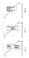
- the figures show a heat exchanging device 1 for use in a temperature or climate control system in a building like e.g. a house 2.
- the temperature or climate control system is constituted by a conventional CH system 3 (including its pipes & tubes, radiators etc. which are not show explicitly here), to which the heat exchanging device 1 -a heat pump which, when used for heating the house 1, is capable to extract heat from the outside air- is attached to cooperate with.
- the device 1 comprises a (first) heat exchange module 4 arranged for exchanging heat with the open air 5 outside the building, i.e. extracting heat from the open air 5 when the house needs to be heated (in summer the same system may be used for cooling the house via the CH water or air circuit as well).
- the device 1 is arranged to cooperate with a housing 6, having air accession openings 7, which housing extends, via an opening 8 in a roof 9 of the building, outside the roof 9, while covering the roof opening 8.
- the device 1, or at least its heat exchange module 4 comprises means for moving it ( figure 1b ) from the inside of the building ( figure 1a ) towards the outside through the roof opening ( figure 1c ), causing that the heat exchange module 4 mainly extends outside the building and is capable to exchange heat directly (i.e. without any use of substantial air channels etc. which are needed in prior art indoor systems) with the open air 5 outside the building via the housing's air accession openings 7.
- the device 1 moreover, comprises means for detachably fixing the heat exchange device or at least its heat exchange module, to the roof, the roof opening, the housing or any other part of thebuilding, which may be formed -as in the embodiment shown in the figures 1a-c by a frame - constituted by sections 11 fixed to the device 1 and a section 12 which is to be fixed to the roof, the roof opening, the housing or any other part of the building.
- -frame section 12 may be made of one part or mounted from several frame section parts 12 which are assembled before fixing it to the roof (opening). Both frame sections 11 and 12 are fit to slide to each another. In this way the device 1 -or at least its heat exchange module 4- can easily be moved from the inside of the building towards the outside via the roof opening, using the frame structure 11-12 for a smooth guidance.
- the device 1 After the device 1 has been lifted completely (see figure 1c ) the device 1 is detachably fixed by means of the support bar 13 which is fixed to the frame section 12 using some bolds 14.
- the heat exchanging device may be a heat pump based system comprising said heat exchange module arranged for exchanging heat with the open air outside the building, as well as a second heat exchange module, interconnected with the first heat exchange module via a high/low pressure refrigerant circuit and arranged for exchanging heat to or from a further climate control system arranged for the distribution and/or generation of heat and/or cold inside the building of house.
Landscapes
- Engineering & Computer Science (AREA)
- Chemical & Material Sciences (AREA)
- Combustion & Propulsion (AREA)
- Mechanical Engineering (AREA)
- General Engineering & Computer Science (AREA)
- Building Environments (AREA)
Abstract
Description
- The present invention concerns a method for installing a heat exchanging device in a building like e.g. a house, the device comprising a heat exchange module which is arranged for exchanging heat with the open air outside the building. Moreover, the invention refers to a heat exchanging device which is arranged for performing this method.
- One aspect of the present invention is to provide a heating/cooling device which can easily be combined with another (e.g. already existing) system e.g. in (dwelling) houses etc. without occupying substantial room.
- Another aspect is to provide a device which can be installed, maintained and repaired without the need for much room and which device can easily be built in and out.
- Yet another aspect of the invention is to provide a device and system having exterior parts (protuding outside the roof) which comply with the desired and/or prescribed aesthetics of the exterior of the house.
- Still another aspect is to provide a device which is capable to provide substantial energy savings when the heat exchanging device has the constitution of a so-called "heat pump" which is very efficient in particular in periods in which the difference between the outside and inside temperature is moderate.
- In order to stimulate the use of such heat pumps (see also http://en.wikipedia.org/wiki/Heat_pump) -meant here are heat pumps which have one heat exchanger exposed to outside air (viz. to extract heat from the outside air and transfer it to the in-house (CH) heating system or vice versa)-a novel configuration has been designed, which is supposed to enable and promote the application of heat pumps as an additional heat source for e.g. domestic use, i.e. in houses and buildings having restricted room to install an additional (heat pump) installation.
- To that end the method according to the invention comprising the following steps:
- providing an opening in a roof of the building;
- providing a housing having one or more air accession openings, the housing extending outside the roof and covering the roof opening;
- moving the heat exchange device or at least its heat exchange module, from the inside of the building towards the outside through the roof opening, causing that the heat exchange module mainly extends outside the building and is capable to exchange heat with the open air outside the building via the housing's air accession openings;
- fixing the heat exchange device or at least its heat exchange module to the roof, the roof opening, the housing or any other part of the building.
- The roof of the relevant house thus is provided with an opening which is covered by a housing which has the functions of:
- protecting the roof opening against rain, wind etc. (the housing thus needs to be proper connected to the surrounding roofing);
- housing the heat exchange module;
- providing aesthetic camouflage of the heat exchange module protruding through the roof (and thus well visible);
- providing -where needed- protection of the exchange module and/or guiding the outside air to (or from) the exchange module).
- The housing may be installed from the inside of the house towards the outside or from the outside (i.e. the outer roof side); the installation of the housing is more or less similar to the installation of a roof window or a dormer window.
- After the housing has been installed and mounted, the heat exchanging device or (when not integrated as one unit) at least the heat exchange module (i.e. the outside air exchange module) can be installed from the inside of the house (e.g. the loft) towards the outside, e.g. by sliding the device or module through the roof opening (covered by the housing) outside and then fixing it to e.g. the roof of roof opening.
- It is, however, preferred, to use a guiding of sliding frame construction, as outlined here:
- providing a frame and fixing it to the roof, the roof opening, the housing or any other part of the building;
- moving the heat exchange device or at least its heat exchange module, from the inside of the building towards the outside through the roof opening, using the frame for guidance;
- fixing the heat exchange device or at least its heat exchange module, to the frame, the roof, the roof opening, the housing or any other part of the building.
- According to this preferred option the use of a (auxiliary) frame is proposed which -in short- may be fastened to the roof (opening) and which is used then to guide the heat exchanging device or the heat exchange module in its motion through the roof opening during installation or de-installation (e.g. for repair or maintenance).
- According to the invention, it is preferred that the heat exchanging device comprises a heat exchange module which is arranged for exchanging heat with the open air outside the building; besides, the preferred device furthermore comprises -or is arranged to cooperate with- a housing, having one or more air accession openings, the housing extending, via an opening in a roof of the building, outside the roof and covering the roof opening; the preferred device, or at least its heat exchange module, furthermore, comprises means for moving it from the inside of the building towards the outside through the roof opening, causing that the heat exchange module mainly extends outside the building and is capable to exchange heat with the open air outside the building via the housing's air accession openings; and the device, moreover, comprises means for detachably fixing the heat exchange device or at least its heat exchange module, to the roof, the roof opening, the housing or any other part of the building.
- It is preferred that the heat exchanging device either comprises -or is arranged to cooperate with- a frame which is arranged to be fixed to the roof, the roof opening, the housing or any other part of the building, where the device -or at least its heat exchange module- is arranged to be moved from the inside of the building towards the outside through the roof opening, using the frame for guidance and the device, moreover, comprises means for detachably fixing the heat exchange device or at least its heat exchange module, to the frame, the roof, the roof opening, the housing or any other part of the building.
- As mentioned earlier, the heat exchanging device may be a heat pump based system comprising said heat exchange module arranged for exchanging heat with the open air outside the building, as well as a second heat exchange module, interconnected with the first heat exchange module via a high/low pressure refrigerant circuit and arranged for exchanging heat to or from a further climate control system arranged for the distribution and/or generation of heat and/or cold inside the building of house.
- The invention will be elucidated now referencing to some figures which will illustrate the present invention, including an exemplary embodiment of the device according tot the invention.
- Figures 1a-c
- illustrate the method according to the invention, performed with an exemplary embodiment of the heat exchange device according to the invention;
- The figures show a heat exchanging device 1 for use in a temperature or climate control system in a building like e.g. a
house 2. In the shown embodiment the temperature or climate control system is constituted by a conventional CH system 3 (including its pipes & tubes, radiators etc. which are not show explicitly here), to which the heat exchanging device 1 -a heat pump which, when used for heating the house 1, is capable to extract heat from the outside air- is attached to cooperate with. The device 1 comprises a (first)heat exchange module 4 arranged for exchanging heat with theopen air 5 outside the building, i.e. extracting heat from theopen air 5 when the house needs to be heated (in summer the same system may be used for cooling the house via the CH water or air circuit as well). - The device 1 is arranged to cooperate with a housing 6, having
air accession openings 7, which housing extends, via an opening 8 in aroof 9 of the building, outside theroof 9, while covering the roof opening 8. The device 1, or at least itsheat exchange module 4, comprises means for moving it (figure 1b ) from the inside of the building (figure 1a ) towards the outside through the roof opening (figure 1c ), causing that theheat exchange module 4 mainly extends outside the building and is capable to exchange heat directly (i.e. without any use of substantial air channels etc. which are needed in prior art indoor systems) with theopen air 5 outside the building via the housing'sair accession openings 7. - The device 1, moreover, comprises means for detachably fixing the heat exchange device or at least its heat exchange module, to the roof, the roof opening, the housing or any other part of thebuilding, which may be formed -as in the embodiment shown in the
figures 1a-c by a frame - constituted bysections 11 fixed to the device 1 and asection 12 which is to be fixed to the roof, the roof opening, the housing or any other part of the building. After theframe section 12 has been fixed to the roof (opening) -frame section 12 may be made of one part or mounted from severalframe section parts 12 which are assembled before fixing it to the roof (opening). Bothframe sections - After the device 1 has been lifted completely (see
figure 1c ) the device 1 is detachably fixed by means of thesupport bar 13 which is fixed to theframe section 12 using somebolds 14. - As mentioned earlier, the heat exchanging device may be a heat pump based system comprising said heat exchange module arranged for exchanging heat with the open air outside the building, as well as a second heat exchange module, interconnected with the first heat exchange module via a high/low pressure refrigerant circuit and arranged for exchanging heat to or from a further climate control system arranged for the distribution and/or generation of heat and/or cold inside the building of house.
Claims (5)
- Method for installing a heat exchanging device in a building like e.g. a house, the device comprising a heat exchange module which is arranged for exchanging heat with the open air outside the building, the method comprising the following steps:- providing an opening in a roof of the building;- providing a housing having one or more air accession openings, the housing extending outside the roof and covering the roof opening;- moving the heat exchange device or at least its heat exchange module, from the inside of the building towards the outside through the roof opening, causing that the heat exchange module mainly extends outside the building and is capable to exchange heat with the open air outside the building via the housing's air accession openings;- fixing the heat exchange device or at least its heat exchange module to the roof, the roof opening, the housing or any other part of the building.
- Method according to claim 1, comprising the steps of:- providing a frame and fixing it to the roof, the roof opening, the housing or any other part of the building;- moving the heat exchange device or at least its heat exchange module, from the inside of the building towards the outside through the roof opening, using the frame for guidance;- fixing the heat exchange device or at least its heat exchange module, to the frame, the roof, the roof opening, the housing or any other part of the building.
- Heat exchanging device for use in a temperature control system in a building like e.g. a house;- the device comprising a heat exchange module which is arranged for exchanging heat with the open air outside the building;- the device either comprising or being arranged to cooperate with a housing, having one or more air accession openings, the housing extending, via an opening in a roof of the building, outside the roof and covering the roof opening;- the device or at least its heat exchange module, comprising means for moving it from the inside of the building towards the outside through the roof opening, causing that the heat exchange module mainly extends outside the building and is capable to exchange heat with the open air outside the building via the housing's air accession openings;- the device, moreover, comprising means for detachably fixing the heat exchange device or at least its heat exchange module, to the roof, the roof opening, the housing or any other part of the building.
- Device according to claim 3,- either comprising or arranged to cooperate with a frame which is arranged to be fixed to the roof, the roof opening, the housing or any other part of the building;- the device or at least its heat exchange module being arranged to be moved from the inside of the building towards the outside through the roof opening, using the frame for guidance;- the device, moreover, comprising means for detachably fixing the heat exchange device or at least its heat exchange module, to the frame, the roof, the roof opening, the housing or any other part of the building.
- Device according to claim 3, being a heat pump based system comprising said heat exchange module arranged for exchanging heat with the open air outside the building, as well as a second heat exchange module, interconnected with the first heat exchange module via a high/low pressure refrigerant circuit and arranged for exchanging heat to or from a further climate control system arranged for the distribution and/or generation of heat and/or cold inside the building of house.
Priority Applications (1)
| Application Number | Priority Date | Filing Date | Title |
|---|---|---|---|
| EP09156484A EP2233855A1 (en) | 2009-03-27 | 2009-03-27 | Method for installing a heat exchanging device in a building |
Applications Claiming Priority (1)
| Application Number | Priority Date | Filing Date | Title |
|---|---|---|---|
| EP09156484A EP2233855A1 (en) | 2009-03-27 | 2009-03-27 | Method for installing a heat exchanging device in a building |
Publications (1)
| Publication Number | Publication Date |
|---|---|
| EP2233855A1 true EP2233855A1 (en) | 2010-09-29 |
Family
ID=41091795
Family Applications (1)
| Application Number | Title | Priority Date | Filing Date |
|---|---|---|---|
| EP09156484A Withdrawn EP2233855A1 (en) | 2009-03-27 | 2009-03-27 | Method for installing a heat exchanging device in a building |
Country Status (1)
| Country | Link |
|---|---|
| EP (1) | EP2233855A1 (en) |
Citations (10)
| Publication number | Priority date | Publication date | Assignee | Title |
|---|---|---|---|---|
| US3270738A (en) * | 1963-02-04 | 1966-09-06 | Rodney A Nielsen | Recessed roof-mounted heater |
| US4203302A (en) * | 1978-07-14 | 1980-05-20 | The Laitram Corporation | Floor mounted air conditioner |
| DE3217137A1 (en) * | 1982-05-07 | 1983-11-10 | Ziehl-Abegg GmbH & Co KG, 7119 Künzelsau | Roof ventilator |
| JPS61213445A (en) * | 1985-03-18 | 1986-09-22 | Misawa Homes Co Ltd | Housing utilizing solar heat |
| DE3640347A1 (en) * | 1986-11-26 | 1988-06-09 | Johann Schoenhammer | Countercurrent heat exchanger |
| US4936101A (en) * | 1989-04-24 | 1990-06-26 | Carrier Corporation | Fan arrangement for thru-the-wall unit |
| WO1991008425A1 (en) * | 1989-12-06 | 1991-06-13 | Turbovent A/S | Heat recovering ventilator |
| JPH04121538A (en) * | 1990-09-10 | 1992-04-22 | Misawa Homes Co Ltd | Outdoor unit installation structure in air conditioner |
| JPH06101873A (en) * | 1992-09-17 | 1994-04-12 | Sekisui Chem Co Ltd | Building with air conditioner |
| EP1184627A1 (en) * | 2000-08-31 | 2002-03-06 | Gastec N.V. | Gas feed-through comprising an indoor heat exchange associated with a heat pump |
-
2009
- 2009-03-27 EP EP09156484A patent/EP2233855A1/en not_active Withdrawn
Patent Citations (10)
| Publication number | Priority date | Publication date | Assignee | Title |
|---|---|---|---|---|
| US3270738A (en) * | 1963-02-04 | 1966-09-06 | Rodney A Nielsen | Recessed roof-mounted heater |
| US4203302A (en) * | 1978-07-14 | 1980-05-20 | The Laitram Corporation | Floor mounted air conditioner |
| DE3217137A1 (en) * | 1982-05-07 | 1983-11-10 | Ziehl-Abegg GmbH & Co KG, 7119 Künzelsau | Roof ventilator |
| JPS61213445A (en) * | 1985-03-18 | 1986-09-22 | Misawa Homes Co Ltd | Housing utilizing solar heat |
| DE3640347A1 (en) * | 1986-11-26 | 1988-06-09 | Johann Schoenhammer | Countercurrent heat exchanger |
| US4936101A (en) * | 1989-04-24 | 1990-06-26 | Carrier Corporation | Fan arrangement for thru-the-wall unit |
| WO1991008425A1 (en) * | 1989-12-06 | 1991-06-13 | Turbovent A/S | Heat recovering ventilator |
| JPH04121538A (en) * | 1990-09-10 | 1992-04-22 | Misawa Homes Co Ltd | Outdoor unit installation structure in air conditioner |
| JPH06101873A (en) * | 1992-09-17 | 1994-04-12 | Sekisui Chem Co Ltd | Building with air conditioner |
| EP1184627A1 (en) * | 2000-08-31 | 2002-03-06 | Gastec N.V. | Gas feed-through comprising an indoor heat exchange associated with a heat pump |
Similar Documents
| Publication | Publication Date | Title |
|---|---|---|
| EP3379164B1 (en) | Mechanical ventilation heat recovery apparatus | |
| WO2008025849A2 (en) | A solar air system with a heat pump | |
| JPWO2008152786A1 (en) | Residential water heater | |
| JP2009235677A (en) | Thermal environment improving system | |
| JP2009516153A (en) | Heat pump system | |
| JP3878636B2 (en) | Solar system house ventilation method | |
| DK2722463T3 (en) | Design module | |
| CN204531058U (en) | A kind of green building environment protection multifunctional body of wall | |
| JP2006097425A (en) | Solar system house ventilation method | |
| JP3848652B2 (en) | Solar system house | |
| JP5051558B1 (en) | Smart eco air conditioning system | |
| KR101102860B1 (en) | Energy Saving Envelope System | |
| CN213362660U (en) | Go into trinity integrated air conditioner structure of wall formula | |
| EP4191185A1 (en) | Air conditioner unit and air conditioner | |
| JP2014015711A (en) | Radiant heat heating and cooling system of building utilizing in-wall-body vent layer | |
| EP2503261A1 (en) | Solar collector with heat sink | |
| KR20190026399A (en) | Cooling and heating system of complex heat source and control method thereof | |
| JP2005241073A (en) | Passive solar system house | |
| CN201237317Y (en) | Temperature regulation apparatus of communication base station | |
| KR102669777B1 (en) | Passive House modular homes and their making method | |
| JP5563325B2 (en) | Building solar collector | |
| CN104296429A (en) | Capillary air conditioning terminal | |
| SG187872A1 (en) | A building facade system | |
| KR100756378B1 (en) | Balcony Heat Exchanger Using Solar Heat | |
| JP2006125774A (en) | Duct and air conditioning system and building |
Legal Events
| Date | Code | Title | Description |
|---|---|---|---|
| PUAI | Public reference made under article 153(3) epc to a published international application that has entered the european phase |
Free format text: ORIGINAL CODE: 0009012 |
|
| AK | Designated contracting states |
Kind code of ref document: A1 Designated state(s): AT BE BG CH CY CZ DE DK EE ES FI FR GB GR HR HU IE IS IT LI LT LU LV MC MK MT NL NO PL PT RO SE SI SK TR |
|
| AX | Request for extension of the european patent |
Extension state: AL BA RS |
|
| AKY | No designation fees paid | ||
| REG | Reference to a national code |
Ref country code: DE Ref legal event code: R108 Effective date: 20110503 |
|
| STAA | Information on the status of an ep patent application or granted ep patent |
Free format text: STATUS: THE APPLICATION IS DEEMED TO BE WITHDRAWN |
|
| 18D | Application deemed to be withdrawn |
Effective date: 20110330 |