EP2233832A1 - Anordnung zur Lichtabgabe mit Leuchtelementen - Google Patents
Anordnung zur Lichtabgabe mit Leuchtelementen Download PDFInfo
- Publication number
- EP2233832A1 EP2233832A1 EP10157307A EP10157307A EP2233832A1 EP 2233832 A1 EP2233832 A1 EP 2233832A1 EP 10157307 A EP10157307 A EP 10157307A EP 10157307 A EP10157307 A EP 10157307A EP 2233832 A1 EP2233832 A1 EP 2233832A1
- Authority
- EP
- European Patent Office
- Prior art keywords
- heat sink
- emitting light
- arrangement
- cooling
- cooling body
- Prior art date
- Legal status (The legal status is an assumption and is not a legal conclusion. Google has not performed a legal analysis and makes no representation as to the accuracy of the status listed.)
- Granted
Links
- 238000001816 cooling Methods 0.000 claims abstract description 61
- 230000015572 biosynthetic process Effects 0.000 claims description 9
- 238000013461 design Methods 0.000 claims description 3
- 238000013016 damping Methods 0.000 claims description 2
- 238000011161 development Methods 0.000 claims description 2
- 239000004636 vulcanized rubber Substances 0.000 claims description 2
- 241000446313 Lamella Species 0.000 abstract description 9
- 229920001296 polysiloxane Polymers 0.000 abstract description 2
- 239000003570 air Substances 0.000 description 12
- 239000007787 solid Substances 0.000 description 11
- 239000002826 coolant Substances 0.000 description 5
- 230000005284 excitation Effects 0.000 description 5
- 238000012546 transfer Methods 0.000 description 5
- 229910052751 metal Inorganic materials 0.000 description 4
- 239000002184 metal Substances 0.000 description 4
- 238000003801 milling Methods 0.000 description 4
- 229920003023 plastic Polymers 0.000 description 4
- 239000012080 ambient air Substances 0.000 description 3
- 230000008901 benefit Effects 0.000 description 3
- 230000008878 coupling Effects 0.000 description 3
- 238000010168 coupling process Methods 0.000 description 3
- 238000005859 coupling reaction Methods 0.000 description 3
- 230000007423 decrease Effects 0.000 description 3
- 239000004033 plastic Substances 0.000 description 3
- 230000005855 radiation Effects 0.000 description 3
- 238000013459 approach Methods 0.000 description 2
- 230000004888 barrier function Effects 0.000 description 2
- 230000005540 biological transmission Effects 0.000 description 2
- 238000009826 distribution Methods 0.000 description 2
- 230000000694 effects Effects 0.000 description 2
- 230000017525 heat dissipation Effects 0.000 description 2
- 239000011159 matrix material Substances 0.000 description 2
- 238000000034 method Methods 0.000 description 2
- 230000010355 oscillation Effects 0.000 description 2
- 238000007493 shaping process Methods 0.000 description 2
- 239000011343 solid material Substances 0.000 description 2
- 230000003595 spectral effect Effects 0.000 description 2
- 241000127225 Enceliopsis nudicaulis Species 0.000 description 1
- 206010063493 Premature ageing Diseases 0.000 description 1
- 208000032038 Premature aging Diseases 0.000 description 1
- 241000220317 Rosa Species 0.000 description 1
- 241000219793 Trifolium Species 0.000 description 1
- 230000006978 adaptation Effects 0.000 description 1
- 230000032683 aging Effects 0.000 description 1
- 229910052782 aluminium Inorganic materials 0.000 description 1
- XAGFODPZIPBFFR-UHFFFAOYSA-N aluminium Chemical compound [Al] XAGFODPZIPBFFR-UHFFFAOYSA-N 0.000 description 1
- 230000015556 catabolic process Effects 0.000 description 1
- 230000008859 change Effects 0.000 description 1
- 239000004020 conductor Substances 0.000 description 1
- 238000005520 cutting process Methods 0.000 description 1
- 230000001934 delay Effects 0.000 description 1
- 230000001419 dependent effect Effects 0.000 description 1
- 230000018109 developmental process Effects 0.000 description 1
- 238000010410 dusting Methods 0.000 description 1
- 239000013013 elastic material Substances 0.000 description 1
- 230000004907 flux Effects 0.000 description 1
- 239000011521 glass Substances 0.000 description 1
- 238000009413 insulation Methods 0.000 description 1
- 239000007788 liquid Substances 0.000 description 1
- 238000012423 maintenance Methods 0.000 description 1
- 238000004519 manufacturing process Methods 0.000 description 1
- 239000000203 mixture Substances 0.000 description 1
- 230000004048 modification Effects 0.000 description 1
- 238000012986 modification Methods 0.000 description 1
- 239000003921 oil Substances 0.000 description 1
- 230000003534 oscillatory effect Effects 0.000 description 1
- 230000008569 process Effects 0.000 description 1
- 230000009467 reduction Effects 0.000 description 1
- 230000000284 resting effect Effects 0.000 description 1
- 239000004065 semiconductor Substances 0.000 description 1
- 238000001228 spectrum Methods 0.000 description 1
- 238000003860 storage Methods 0.000 description 1
- 230000003319 supportive effect Effects 0.000 description 1
- 230000002195 synergetic effect Effects 0.000 description 1
- 210000002105 tongue Anatomy 0.000 description 1
- 238000012549 training Methods 0.000 description 1
- 208000008918 voyeurism Diseases 0.000 description 1
- XLYOFNOQVPJJNP-UHFFFAOYSA-N water Substances O XLYOFNOQVPJJNP-UHFFFAOYSA-N 0.000 description 1
- 238000004804 winding Methods 0.000 description 1
Images

Classifications
-
- F—MECHANICAL ENGINEERING; LIGHTING; HEATING; WEAPONS; BLASTING
- F21—LIGHTING
- F21V—FUNCTIONAL FEATURES OR DETAILS OF LIGHTING DEVICES OR SYSTEMS THEREOF; STRUCTURAL COMBINATIONS OF LIGHTING DEVICES WITH OTHER ARTICLES, NOT OTHERWISE PROVIDED FOR
- F21V29/00—Protecting lighting devices from thermal damage; Cooling or heating arrangements specially adapted for lighting devices or systems
- F21V29/50—Cooling arrangements
- F21V29/60—Cooling arrangements characterised by the use of a forced flow of gas, e.g. air
- F21V29/63—Cooling arrangements characterised by the use of a forced flow of gas, e.g. air using electrically-powered vibrating means; using ionic wind
-
- F—MECHANICAL ENGINEERING; LIGHTING; HEATING; WEAPONS; BLASTING
- F21—LIGHTING
- F21V—FUNCTIONAL FEATURES OR DETAILS OF LIGHTING DEVICES OR SYSTEMS THEREOF; STRUCTURAL COMBINATIONS OF LIGHTING DEVICES WITH OTHER ARTICLES, NOT OTHERWISE PROVIDED FOR
- F21V29/00—Protecting lighting devices from thermal damage; Cooling or heating arrangements specially adapted for lighting devices or systems
- F21V29/50—Cooling arrangements
- F21V29/70—Cooling arrangements characterised by passive heat-dissipating elements, e.g. heat-sinks
- F21V29/74—Cooling arrangements characterised by passive heat-dissipating elements, e.g. heat-sinks with fins or blades
- F21V29/77—Cooling arrangements characterised by passive heat-dissipating elements, e.g. heat-sinks with fins or blades with essentially identical diverging planar fins or blades, e.g. with fan-like or star-like cross-section
-
- F—MECHANICAL ENGINEERING; LIGHTING; HEATING; WEAPONS; BLASTING
- F21—LIGHTING
- F21V—FUNCTIONAL FEATURES OR DETAILS OF LIGHTING DEVICES OR SYSTEMS THEREOF; STRUCTURAL COMBINATIONS OF LIGHTING DEVICES WITH OTHER ARTICLES, NOT OTHERWISE PROVIDED FOR
- F21V29/00—Protecting lighting devices from thermal damage; Cooling or heating arrangements specially adapted for lighting devices or systems
- F21V29/50—Cooling arrangements
- F21V29/70—Cooling arrangements characterised by passive heat-dissipating elements, e.g. heat-sinks
- F21V29/74—Cooling arrangements characterised by passive heat-dissipating elements, e.g. heat-sinks with fins or blades
-
- F—MECHANICAL ENGINEERING; LIGHTING; HEATING; WEAPONS; BLASTING
- F21—LIGHTING
- F21V—FUNCTIONAL FEATURES OR DETAILS OF LIGHTING DEVICES OR SYSTEMS THEREOF; STRUCTURAL COMBINATIONS OF LIGHTING DEVICES WITH OTHER ARTICLES, NOT OTHERWISE PROVIDED FOR
- F21V29/00—Protecting lighting devices from thermal damage; Cooling or heating arrangements specially adapted for lighting devices or systems
- F21V29/50—Cooling arrangements
- F21V29/70—Cooling arrangements characterised by passive heat-dissipating elements, e.g. heat-sinks
-
- F—MECHANICAL ENGINEERING; LIGHTING; HEATING; WEAPONS; BLASTING
- F21—LIGHTING
- F21Y—INDEXING SCHEME ASSOCIATED WITH SUBCLASSES F21K, F21L, F21S and F21V, RELATING TO THE FORM OR THE KIND OF THE LIGHT SOURCES OR OF THE COLOUR OF THE LIGHT EMITTED
- F21Y2115/00—Light-generating elements of semiconductor light sources
- F21Y2115/10—Light-emitting diodes [LED]
Definitions
- the present invention relates to an arrangement for emitting light with luminous elements, in particular LEDs, and a thermally coupled to the luminous elements heat sink.
- thermal resistance between barrier layers of the individual LEDs, for example, combined as an LED unit, and ambient air can be significantly reduced by a heat sink, which further corresponds to a cooling medium.
- the LED unit for example a carrier or a printed circuit board with an LED arrangement, is mounted on a cooling plate or on a heat sink and thermally connected, so that the thermal resistance between the barrier layer and the surrounding air decreases.
- the heat sink like a transmission element, part of a transmission path, quickly dissipates the heat loss generated by heat conduction from the heat-generating component as a source to a sink, and then releases the heat loss to the environment through exchange processes such as heat radiation and convection.
- the behavior of the heat sink or the heat transfer from a heat source to the surrounding cooling medium depends primarily on the temperature difference, the effective surface and the flow velocity of the cooling medium.
- monolithically integrated semiconductor circuits for example block or hybrid amplifiers, as far as comparable to an LED unit, are thermally coupled to a solid heat sink for heat dissipation.
- the US 6,863,421 shows a lamp housing for an image projector lamp, in the small space an air flow is generated with a fan. Inside the chamber, in which the burner of the lamp is located, a plurality of ribs on the inside of the chamber is arranged. The fins are used for shaping the flow and improving the air mixture with the ambient air, which is blown into the interior of the lamp via a fan. To counteract a significant noise, the flow rate should be low.
- the present invention has for its object to provide a heat sink with improved properties for improved heat transfer, so that LED lights can be made low with a large radiant power.
- an arrangement for emitting light is provided with luminous elements, in particular LEDs, and a thermally coupled to the luminous elements heat sink, characterized in that the heat sink is designed such that it completely or at least a part or a portion of its surface vibrates ,
- the heat sink may consist of a solid part, which is at rest, or firmly connected to a housing part such as the lamp housing or a support structure, and a part, such as. Louvers or cooling ends leaking from a solid base that vibrate.
- the image may be taken from vibrating or fan-out tongues that release heat output to the environment and generate their own flow or turbulence.
- the heat sink is improved in the heat conduction and its transport properties. Thermal resistance and heat capacity of the moving heat sink are much lower than compared to a normal heat sink of the same type in which there are laminar flows.
- According to the first aspect of the invention is remarkably dissipated by the LED unit, possibly very high power dissipation dissipates much faster, or, as would be a heat sink, which would actually be orders of magnitude larger and more massive than the one used to very high To cope with heat loads.
- the above arrangement for emitting light is characterized in that the cooling body is cylindrical and has radially encircling cooling fins.
- the aforementioned cooling fins can also be milling a solid cylinder, for example, an array of parallel milling. Further, the millings may run longitudinally or transversely of an elongated cylinder to yield a pattern or raster.
- the protruding ends may be square or round.
- the arrangement for emitting light according to the first or the second aspect is characterized in that the shape or the design of the heat sink promotes the emergence of a turbulent air flow.
- a change in the properties of the heat sink can be provided by a profiling.
- the profile may be rough, corrugated or wavy, scaled or roof-plate patterned, have bumps or irregularities in the course.
- the arrangement for emitting light according to the first to third aspects is characterized in that the heat sink has cooling slats, corrugations, millings, polished or rough prisms.
- the arrangement for emitting light according to the first to fourth aspect is characterized in that the heat sink is mechanically coupled to at least one drive element or a vibration generator such as a piezoelectric element, a voice or plunger coil.
- the mechanical coupling can be done for example by screwing the vibration generator to the heat sink.
- a drive is used.
- a small electric motor can be used as a vibration motor.
- the arrangement for emitting light according to the fifth aspect is characterized in that a time-varying voltage is applied to the vibration generator.
- a time-varying voltage may be understood as a waveform of a signal having an amplitude and a frequency and a start or reference phase.
- the light emitting device is characterized in that the heat sink comprises two oscillators.
- the vibration generators are arranged at different locations of the heat sink.
- the vibration generators are driven with different voltage curves. Over at least a portion of the heat sink can form interference that promotes a turbulent flow, a vortex or a vortex formation.
- the light emitting device is characterized in that the lighting elements are mounted on the heat sink.
- the heat sink and the light elements or a support for the light-emitting elements are connected via a conductive or insulating, vibration-elastic or vibration damping medium, such as a layer of vulcanized rubber.
- a conductive or insulating, vibration-elastic or vibration damping medium such as a layer of vulcanized rubber.
- an LED emitter for use for emitting light with a heat sink thermally coupled to luminous elements.
- the LED radiator is characterized in that it vibrates completely or at least part or a portion of its surface.
- the LED emitter for use in light emission according to the above aspect is provided, and is characterized in that the heat sink according to any one of the second to fifth aspects is performed.
- the LED radiator according to the ninth or tenth aspect is characterized in that the heat sink having at least one drive element or a vibration generator according to the sixth and the seventh aspect.
- the LED radiator according to one of the ninth to eleventh aspects is characterized in that the lighting elements are mounted on the heat sink.
- the heat sink and the lighting elements or a support for the lighting elements are connected via at least one intermediate layer according to the eighth aspect.
- a conductive layer, a film or a layer arrangement of plastics may be provided, wherein at least one conductive plastic is contained.
- Conductivity in the above refers to electric current and / or thermal heat conductivity.
- the aforementioned layer can also form a thermocouple, which in addition to the function for the heat transfer and for measuring an electrical or thermal resistance can be used.
- the thermocouple may be in the above case, a sensor and / or a part of a control loop in the sense of the aforementioned aspects.
- the LED radiator according to one of the ninth to twelfth aspects is characterized in that at least one heat sink coupled to at least one luminous element is present.
- a plurality of small heat sinks according to one of the above aspects can be combined in an arrangement of spaced apart individual systems, for example a matrix.
- the LED radiator according to the thirteenth aspect is characterized in that the at least one heat sink completely or at least a part or a portion of the surface of a heat sink vibrates in alternation.
- vibration as mentioned above, it is meant, in general, vibrations and waves containing mechanical vibrations and waves, besides dynamically changing characteristics of a physical quantity, such as a spring force.
- oscillating rod with one-sided storage is called.
- Vibrating may include a portion or parts of an electromagnetic spectrum over a low frequency, for example, in the range of 0 to 100 hertz, a frequency in the audio range of 20 hertz to 20 kilohertz, KHz, or a frequency in the range of 20 to 100 KHz.
- the orientation and direction of the vibration may be longitudinal, transverse or circular depending on the excitation of the heat sink according to any one of the fifth to seventh aspects related to driving the heat sink.
- a reflector is provided, which is characterized in that the reflector has a shape that favors the heat sink when creating a turbulent or vortex-shaped air flow.
- the heat sink it is provided either as the heat sink circumferentially ribbed metal block, preferably made of extruded aluminum, as solid metal mold, as circumferentially corrugated metal plate, as a solid core with pressed-in, introduced via a press fit, or soldered slats or milled from solid material to manufacture.
- the heat sink can also be designed as a stamped, shaped or folded laminated core, or as attachable cooling star, cooling ring and cooling vanes.
- a screened pattern may be present as a screened array having a depth (length of the cooling fins or cubes viewed from the base).
- a rasterized pattern is for example a diamond-shaped milled into a solid blank training on cooling fins orderauuten.
- the heat sink should preferably consist of good heat-conducting material and preferably have a dark and very large surface area.
- the heat sink should be mounted vertically in order to exploit the chimney effect in the air circulation can.
- the LED unit is to be mounted, for example, in the middle, and should then radiate from the center point-like outward in the direction of the circumference. Furthermore, resting air of the environment should be present without additional heat radiation.
- a vibration drive is to be mounted, for example, a piezoelectric element which vibrates or the heat sink.
- the heat sink moves.
- the individual fins, or cooling ends perform oscillatory movements.
- the movement of a lamella or a wall can take place either around its clamping or connection to the solid base, for example swinging back and forth, but also slightly distorted to be twisted or twisted about an axis along the clamping.
- the arrangement itself can also vibrate.
- the type of vibration (waveform) and the spatial formation on the surface of the lamella or on the heat sink, for example, a running along waves over a grid arrangement, should be determined by the geometry and shape of the lamella.
- the drive can certain Vibration patterns are also selectively excited.
- the drive in the case of an electric piezoelectric element or an electromagnetic coil, or a vibration motor, by a corresponding waveform (voltage, current, reference phase angle, waveform, wave (transverse, longitudinal), spectral components) via a feed, preferably a cable or a coaxial line, which causes a corresponding vibration behavior in conjunction with the geometry of the slats.
- the LED arrangement for emitting light with luminous elements is and will remain maintenance-free for a long time, protected against premature aging and sudden breakdown.
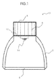
- Fig. 1 an LED array 10 according to the first embodiment is shown from the front side.
- the luminaire housing 2 is shown by two concave inwardly curved side parts in sections and with a view into the interior of the LED assembly 10 cut free.
- the aforementioned side parts can therefore be radially encircling and form a half shell or hemisphere.
- the side parts In the case of an elongated LED light you can Fig. 1 , alternatively interpreted, even beyond the drawing plane imagine linearly extended, so that the side parts then represent a right and a left part of an elongated profile.
- a light exit element 4 is provided.
- the light exit element can be a transparent or slightly metal-coated glass plate in conjunction with a grid or a raster reflector.
- the light exit element can be detachably connected to the luminaire housing 2.
- the heat sink 6 connects.
- the connection of the heat sink to the lamp housing can be elastically by an (outside the drawing standing) intermediate layer of an elastic material, which also seals.
- the heat sink 6 has here, purely by way of example, a regular structure of cooling fins 8.
- the LED unit 12 is suitably mechanically, thermally, possibly also electrically connected to the heat sink.
- an LED 14 is shown on the LED unit, it being understood that the LED unit 12 also has a larger area of the heat sink 6 and can lead multiple LEDs in a matrix arrangement.
- the cooling fins 8 serve to cool the LED unit 12, that is to say for the dissipation of the loss heat incurred during the light generation.
- the heat loss is passed from the inside of the LED unit on the heat sink and at the ends, for example, shown as vertical lines in the heat sink 6, transported to the outside and discharged into the exterior.
- the heat sink 6 can be set in vibration by a drive (lying outside the drawing). In operation, the formation of a laminar boundary or insulating layer remains. Rather, turbulences, eddies and a higher air velocity occur due to the vibration of the heat sink surface or at the ends of the heat sink. The mixing of the ambient air is improved. The heat dissipation becomes noticeably more effective.
- the dusting of the heat sink fins is also prevented, overtemperatures with retroactive effect on the LED element are avoided.
- the driven lamellae move and are sufficiently ventilated or swirled around.
- Fig. 1a shows the LED arrangement Fig. 1 in an oblique view, wherein a radially encircling shape of the lamp housing 2 was based on the LED arrangement.
- symmetrically distributed over the circumference sections may be formed as a kind of side window 3 of a transparent plastic, if a light exit to the side is desired.
- the one or more side windows can like the light exit element 4 in Fig. 1 It may be desirable to provide a roughened surface for a diffuser for uniform light distribution.
- an egg, elliptical or parabolic design of the lamp housing can be selected.
- the cooling fins 8 of the heat sink 6 are in Fig. 1a elongated parallel spaced and have a certain thickness.
- the thickness can preferably be chosen so that the blade is capable of vibration.
- the protruding surface may be rough, corrugated or shingled or roof-plate-shaped, it may have a height or depth profile or unevenness along the lamella.
- the aforesaid allows to reduce laminar flows at the fin and to promote formation of turbulence.
- the drive of the heat sink can also be supported. Conversely, the above can be taken into account in the type of driving of the drive in terms of amplitude, frequency and waveform.
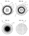
- Fig. 2a is a view from above of the heat sink 20 a shown.
- the heat sink 20a can be out as a heat sink 6 Fig. 1 Insert with the luminaire housing 2.
- a circulating cooling ring 22 was used, which can also be designed as a so-called. Heatpipe.
- the vertical lines in Fig. 1 correspond to the outwardly facing rounded corners of the cooling ring.
- the cooling ring can be milled or cast from solid material.
- the cooling ring is arranged on a bottom plate 24 and a solid base plate.
- the outer border 23 can serve as a borderline for the dimension of the base plate.
- lamellae may also be connected to a ring-shaped circumferential tube as ring radiator which is in connection with a bottom plate 24 of the heat sink 20a, with a coolant circulating.
- a ring-shaped circumferential tube as ring radiator which is in connection with a bottom plate 24 of the heat sink 20a, with a coolant circulating.
- a coolant circulating In the bottom plate then inside extending recesses or cooling coils are provided.
- Fig. 2a In the middle of Fig. 2a is, purely by way of example as a heat source, in turn, the LED unit 12 and the LED 14 located.
- the cooling ring corresponds to Fig. 2a a revolving closed shaft or spiraling.
- the cooling ring in the present case designed with 20 regular and rounded turns or periods of the course of the wall, can also have a different number of walls or a different wavelength.
- the waveform of the circuit can be changed. For example, instead of the curves 26, rectangular or trapezoidal walls or lamella walls may also be possible.
- individual walls may be missing or surfaces may be flat, ie. there are missing sections in the rotating shaft.
- a rotating spring can be used as a cooling ring.
- the spring can run around the circumference several times, as in the case of winding a coil, and can be helically tapered upwards or formed as a coiled helix.
- the principle of the heat pipe can be combined with a flat coil.
- a tube is wound in a coil shape from inside to outside. Inside the flat coil circulates coolant, which is thermally conductive, electrically conductive, or insulating or magnetic. At the flat coil is an AC voltage. Since it can be achieved by suitable control that flat coils are colder inside than outside, anyway, a temperature difference form the center from the center to form the circumference, you can apply the principle of the counterflow cooler advantageous by bringing the output of the cooling coils of the massive heat sink to the center of the base and connects to the entrance of the coil-shaped tube.
- a closed wheel curve running over the circumference of a geometry as a so-called ordinary cycloid, similar to the two-way-rectified variant of the aforementioned closed shaft as so-called stretched cycloids.
- the scope of the geometry may be a conic, like a circle, but also a polygon. If a circumferential thin tube is provided, this can be coiled as so-called. Entwined cycloids.
- a heat sink 20b is shown in which the star-shaped starting from a center (originally star-shaped) profile was rotated in the plane of the drawing.
- a kind of right rotation is formed at tangentially outwardly extending heat sink ends 28 as the outer ends of the cooling fins 8b.
- At the heat sink ends 28 may have a cylindrical or polygonal bulge, Umkragung or orbiting with a radius 28a to avoid sharp edges.
- the radius 28a is shown in the drawing at two adjacent peaks representative of the other ends. The continuation is indicated by three points "", as far as all peaks receive a radius 28a;
- the slats can also be shortened or compressed.
- the radius 28a at the fin end, the thermal coupling can be optimized to the outside space at the top of the cooling fin and improve the radiation behavior and the large-signal characteristics of the heat sink.
- the mechanical vibration behavior can be optimized.
- the heat sink 20b is thermally connected to a (not shown) bottom plate 30 cohesively, positively or releasably connected. Inside the heat sink, a circular recess is provided, which preferably has holes, for example, for attachment to the LED unit 12 with LED 14 and to carry out the supply cable and control lines.
- Fig. 2c shows a further massive heat sink 20c in plan view with a star-shaped or sun-ray-like profile as so-called.
- Sun-shape heat sink or sunray heat sink here means that a solid cylindrical core is present in the center with a circular circumference here. From the origin or middle spring a variety of so-called. Sun rays or sunshine roads.
- both the number of beams mentioned above, the circumference of the solid core, and the ratio between the beam length and core circumference can be chosen for the largest possible surface for the heat exchange. It goes without saying that one or more beams can be dispensed with on one side, for example for the supply of a supply line for the LED element, if this is preferred for constructional reasons.
- the LED element (not shown) can be thermally connected to the bottom of the heat sink.
- Fig. 1 indicated as an example was chosen so that the ends of the heat sink all the same length protrude from a center.
- a triangular cross-section was chosen, which tapers to the outside. The above is missing, however, when a cylinder blank, only perpendicular to the circumference in the direction of the center along and / or transversely milled or rasterized.
- the surfaces in the direction of rotation may also have a corrugated profile or a surface structure.
- the above profile allows the following advantage: If the heat sink is excited at a plurality of substantially similar ends 28c in the vicinity of the natural or resonant frequency, which also naturally only a small amount of energy must be expended, the drive can be designed accordingly simple, arises from the multiple resonances, time delays and reflections of the vibrating ends among each other a kind of Hall with a noise component.
- the above-mentioned noise component is again advantageous for improving the cooling properties.
- the formation of turbulence is enhanced by the oscillating or rushing heat sink fins. The result is a synergistic effect.
- the improved turbulence of the cooling air improves the cooling of the LED element.
- the form or beam shape of the ends 28c can be used to influence the type of noise, reverberation times and the spectral density distribution of the resonances or the clinking of the heat sink, so as to favor a uniform noise of the heat sink.
- a simple control circuit with a voltage-controlled oscillator can serve, which can oscillate in the range of the expected resonance frequencies.
- As supplied from a sensor control voltage is the amplitude of the vibration of the heat sink.
- the circuit increases the control voltage slowly, ie. the oscillator frequency increases.
- the increase in the oscillator frequency continues until the control voltage drops again.
- the amplitude of the natural oscillation decreases after exceeding the resonance point again.
- the resonance range of the heat sink can be passed.
- the proximity of the resonant frequency is thus reached when the control voltage tends to its maximum, so the changes are always larger and almost a balance between control voltage and oscillator frequency would set.
- the optimum excitation frequency is preferably chosen slightly in addition to the resonant frequency of the heat sink, alternatively in the case of a harmonic.
- housing resonances of the LED array should be considered. For small excitation amplitudes, it is also possible to tune to the resonant fundamental frequency of the heat sink.
- the heat sink sufficiently vibrates, so that the formation of laminar flows is omitted, but still no significant noise emanates from the LED array.
- Fig. 2c and Fig. 2b can be combined.
- Fig. 2c set and running upward is a rotation about a common center axis of the slats before on the basis of Fig. 2b , but contrary to both drawings the same number of radii are used.
- the heat sink actually corresponds to a massive stationary fan wheel which has oscillating ends.
- the air flowing past the heatsink itself generates eddies and possibly even a little cold.
- the heat sink is set in vibration, for example, if tuned to resonances, so that the ends have noticeable or a visible oscillation amplitude, then the use of a fan as an additional component can be omitted as well as the problem of air mixing.
- the heat sink generates its own flow. It can be provided larger cooling capacities.
- Fig. 2d shows a further massive heat sink 20d with wavy circumferential profile as a modification of Fig. 2a .
- the cooling fins are compared to Fig. 2b run very short and bring rather minimal surface enlargement, but at maximum bulkiness of the heat sink.
- the above should show in comparison to the preceding figures, the possibilities of variation essential, the function determining parameter of the heat sink, in particular heat capacity, thermal resistance and flow velocity at the surfaces.
- the outer border serves as an orientation aid for the circumference of the base plate.
- roll curves may be mentioned as geometry shapes for a heat sink, in which circles of different diameters roll onto or into one another, in particular a rose curve, a clover leaf or a toothed wheel.
- the LED element (unillustrated) at the bottom (or below the plane of the drawing according to FIG Fig. 1 ) are thermally connected to the heat sink. It is understood that instead of the star-shaped or toothed configurations, polygons can also be used.
- the shape allows the example of Fig. 2a a maximum rate of airflow circulation so that the maximum heat can be dissipated from the LED unit.
- the above is achieved without additional energy, so that the cooling efficiency is very high.
- the present invention thus provides a simple, elegant and effective way to promote a well-tempered area of an LED array, in particular a luminaire with individual LED luminous elements of an LED luminaire.
- the cooling by the vibrating heat sink with assistive shaping is active and allows the benefits and superiority that an LED array according to the present invention offers in terms of economy, lifetime, freedom from maintenance, and reliability to be exploited and to benefit the user.
- the cooling by the vibration heat sink is also so good of the cooling efficiency by utilizing selectively by the drive, supportive or by the heat sink vorsentbaren turbulence that LED units can be operated even at high ambient temperatures and maximum power at optimum temperatures.
Landscapes
- Engineering & Computer Science (AREA)
- General Engineering & Computer Science (AREA)
- Arrangement Of Elements, Cooling, Sealing, Or The Like Of Lighting Devices (AREA)
Abstract
Description
- Die vorliegende Erfindung betrifft eine Anordnung zur Lichtabgabe mit Leuchtelementen, insbesondere LEDs, und einem thermisch mit den Leuchtelementen gekoppelten Kühlkörper.
- Die Arbeitsweise einer LED-Leuchte, bei der relativ hohe Lichtströme erzielt werden sollen, bedingt, dass eine erhebliche Menge an Wärme effektiv abzuführen ist.
- Der Wärmewiderstand zwischen Sperrschichten der einzelnen LEDs, beispielsweise als LED-Einheit zusammengefasst, und umgebender Luft kann durch einen Kühlkörper, merklich vermindert werden, der weiters mit einem Kühlmedium korrespondiert.
- Prinzipiell wird die LED-Einheit, beispielsweise ein Träger oder eine Leiterplatte mit einer LED-Anordnung, auf ein Kühlblech bzw. an einen Kühlkörper befestigt und thermisch verbunden, so dass der Wärmewiderstand zwischen Sperrschicht und umgebender Luft sinkt.
- Um den Wärmeübergang zwischen LED-Einheit und Kühlkörper zu begünstigen, ist es üblich, die Kontaktfläche plan bzw. eben herzustellen.
- Funktionell soll der Kühlkörper wie ein Übertragungselement ein Teil einer Übertragungsstrecke die erzeugte Verlustwärme durch Wärmeleitung vom wärmeerzeugenden Bauelement als einer Quelle rasch zu einer Senke weg- bzw. ableiten, bzw., die Verlustwärme dann durch Austauschprozesse wie Wärmestrahlung und Konvektion an die Umgebung abgeben.
- Das Verhalten des Kühlkörpers bzw. der Wärmeübergang von einer Wärmequelle zum umgebenden Kühlmedium, bevorzugt Luft (ggf. auch Wasser oder andere Flüssigkeiten wie Öle) ist in erster Linie von der Temperaturdifferenz, der wirksamen Oberfläche und der Strömungsgeschwindigkeit des Kühlmediums abhängig.
- Nach dem Stande der Technik werden monolithisch integrierte Halbleiterschaltungen, beispielsweise Block- bzw. Hybridverstärker, soweit vergleichbar mit einer LED-Einheit, thermisch mit einem massiven Kühlkörper zur Wärmeableitung gekoppelt.
- Insofern scheint bei vorgenanntem Ansatz zwar eine etwas bessere thermische Ankopplung bzw. Impedanzanpassung an den Außenraum zur Wärmeabfuhr möglich. Aber trotzdem stellt man im praktischen Betrieb fest, dass bei herkömmlichen Ansätzen ein gewisses Zurückbleiben der tatsächlichen Kühlleistung hinter der erforderlichen Kühlleistung eintritt. Entsprechende Überdimensionierung des Kühlkörpers ist erforderlich. Weiter bestehen Gradienten im Wärmeübergang, bzw. liegt eine Art stationäre Isolationsschicht vor, so dass die Verlustwärme nur zu einem Teil und auch lokal unterschiedlich abgeführt wird.
- Die
US 6,863,421 zeigt ein Lampengehäuse für eine Bildprojektorlampe, in der auf kleinem Raum eine Luftströmung mit einem Lüfter erzeugt wird. Im Inneren der Kammer, in sich der Brenner der Lampe befindet, ist eine Mehrzahl an Rippen an der Innenseite der Kammer angeordnet. Die Rippen dienen zur Strömungsformung und Verbesserung der Luftmischung mit der Umgebungsluft, die über einen Lüfter ins Innere der Lampe eingeblasen wird. Um einer erheblicher Geräuschentwicklung entgegen zu wirken, sollte die Strömungsgeschwindigkeit niedrig sein. - Es wäre daher wünschenswert, den Kühlkörper so zu verbessern, dass eine Wärmeabgabe unter Meidung der obengenannten Nachteile möglich ist.
- Der vorliegenden Erfindung liegt die Aufgabe zugrunde, einen Kühlkörper mit verbesserten Eigenschaften für verbesserten Wärmetransport zu schaffen, so dass LED-Leuchten mit einer großen Strahlungsleistung günstig hergestellt werden können.
- Die Aufgabe wird durch eine Anordnung zur Lichtabgabe mit Leuchtelementen gemäß dem Anspruch 1 und durch eine Kühleinrichtung zur Verwendung in einer Anordnung zur Lichtabgabe mit Leuchtelementen gemäß dem Anspruch 9 gelöst. Vorteilhafte Weiterbildungen sind Gegenstand der abhängigen Ansprüche.
- Demgemäß wird nach einem ersten Aspekt ist eine Anordnung zur Lichtabgabe mit Leuchtelementen vorgesehen, insbesondere LEDs, und einem thermisch mit den Leuchtelementen gekoppelten Kühlkörper, dadurch gekennzeichnet, dass der Kühlkörper derart ausgestaltet ist, dass dieser vollständig oder mindestens ein Teil oder ein Abschnitt seiner Oberfläche vibriert. Der Kühlkörper kann aus einem massiven Teil bestehen, der in Ruhe ist, bzw. fest mit einem Gehäuseteil wie dem Leuchtengehäuse oder einer Tragkonstruktion verbunden, und einem Teil, wie zB. Lamellen oder von einer massiven Basis auslaufende Kühlenden, die vibrieren. Bei Vorstehenden kann das Bild von schwingenden oder fächernden Zungen herangezogen werden, die Wärmeleistung an die Umgebung abgeben und ihre eigene Strömung oder Verwirbelung erzeugen. Indem die Kühlkörperenden des Kühlkörpers schwingen, wird ein bewegter bzw. dynamischer Kühlkörper geschaffen. Weiter gelingt es, eine bewegte oder turbulente Strömung an den Wandungen bzw. Kühlflächen zu erzeugen. Vorstehendes erhöht die Leistungsfähigkeit der Kühleinrichtung erheblich. Der Kühlkörper wird in der Wärmeleitung bzw. seinen Transporteigenschaften verbessert. Wärmewiderstand und Wärmekapazität des bewegten Kühlkörpers sind wesentlich geringer als im Vergleich zu einem normalen Kühlkörper gleicher Bauart, bei dem laminare Strömungen vorliegen. Nach dem ersten Aspekt der Erfindung wird bemerkenswerterweise die von der LED-Einheit erzeugte, unter Umständen sehr hohe Verlustleistung viel schneller abgeführt, bzw., als läge ein Kühlkörper vor, der eigentlich um Größenordnungen größer und massiver sein müßte als der eingesetzte, um sehr hohe Wärmebelastungen zu bewältigen.
- Nach einem zweiten Aspekt ist die vorstehende Anordnung zur Lichtabgabe dadurch gekennzeichnet, dass der Kühlkörper zylinderförmig ist und radial umlaufende Kühlrippen aufweist. Vorgenannte Kühlrippen können aber auch Fräsungen einen massiven Zylinder sein, beispielsweise eine Anordnung paralleler Fräsungen. Weiter können die Fräsungen in Längs- oder Querrichtung eines länglichen Zylinders verlaufen, und ein Muster oder ein Raster ergeben. Die abstehenden Enden können quadratisch oder rund ausgebildet sein.
- Nach einem dritten Aspekt ist die Anordnung zur Lichtabgabe gemäß dem ersten oder dem zweiten Aspekt dadurch gekennzeichnet, dass die Form oder die Ausgestaltung des Kühlkörpers das Entstehen einer turbulenten Luftströmung begünstigt. Vorstehend kann eine Veränderung der Eigenschaften des Kühlkörpers durch eine Profilierung vorgesehen sein. Das Profil kann rauh, geriffelt oder wellig, schuppen- oder dachplattenförmig bemustert sein, Unebenheiten oder Unregelmäßigkeiten im Verlauf aufweisen.
- Nach einem vierten Aspekt ist die Anordnung zur Lichtabgabe gemäß dem ersten bis dritten Aspekt dadurch gekennzeichnet, dass der Kühlkörper Kühllammellen, Riffelungen, Fräsungen, polierte oder raue Prismen aufweist.
- Nach einem fünften Aspekt ist die Anordnung zur Lichtabgabe gemäß dem ersten bis vierten Aspekt dadurch gekennzeichnet, dass der Kühlkörper mit mindestens einem Antriebselement oder einem Schwingungserzeuger wie einem Piezoelement, einer Sprach- oder Tauchspule mechanisch gekoppelt ist. Die Mechanische Kopplung kann beispielsweise durch ein Anschrauben des Schwingungserzeugers an den Kühlkörper erfolgen. Zur Vibration wird ein Antrieb eingesetzt. Auch kann ein kleiner Elektromotor als Vibrationsmotor eingesetzt werden.
- Nach einem sechsten Aspekt ist an der Anordnung zur Lichtabgabe gemäß dem fünften Aspekt dadurch gekennzeichnet, dass an dem Schwingungserzeuger eine zeitlich veränderliche Spannung anliegt. Unter einer zeitlich veränderten Spannung kann eine Wellenform eines Signals verstanden werden, die eine Amplitude und eine Frequenz und eine Start- oder Bezugsphase aufweist.
- Nach einem siebten Aspekt ist die Anordnung zur Lichtabgabe gemäß einen der vorhergehenden Aspekte dadurch gekennzeichnet, dass der Kühlkörper zwei Schwingungserzeuger aufweist. Die Schwingungserzeuger sind an verschiedenen Orten des Kühlkörpers angeordnet. Die Schwingungserzeuger werden mit unterschiedlichen Spannungsverläufen angesteuert. Über mindestens einem Teil des Kühlkörpers lassen Interferenzen ausbilden, die eine turbulente Strömung, eine Strudel- oder eine Wirbelbildung begünstigen.
- Nach einem achten Aspekt ist die Anordnung zur Lichtabgabe gemäß einen der vorhergehenden Aspekte dadurch gekennzeichnet, dass die Leuchtelemente auf dem Kühlkörper montiert sind. Der Kühlkörper und die Leuchtelemente bzw. ein Träger für die Leuchtelemente sind über ein leitfähiges oder isolierendes, schwingungselastisches oder schwingungsdämpfendes Medium, wie einer Schicht aus vulkanisiertem Kautschuk verbunden. Neben einem Kautschuk oder Gummi können auch elastische und hitzebeständige und alterungsresistente Kunststoffe anderer Art, daneben Silikone verwendet werden.
- Nach einem neunten Aspekt ist ein LED-Strahler für die Verwendung zur Lichtabgabe mit einem thermisch mit Leuchtelementen gekoppelten Kühlkörper vorgesehen. Der LED-Strahler ist dadurch gekennzeichnet, dass dieser vollständig oder mindestens ein Teil oder ein Abschnitt seiner Oberfläche vibriert.
- Nach einem zehnten Aspekt liegt der LED-Strahler für die Verwendung zur Lichtabgabe nach vorstehendem Aspekt vor und ist dadurch gekennzeichnet, dass der Kühlkörper nach einem der zweiten bis fünften Aspekte ausgeführt ist.
- Nach einem elften Aspekt ist der LED-Strahler nach dem neunten oder zehnten Aspekt dadurch gekennzeichnet, dass der Kühlkörper mit mindestens einem Antriebselement oder einem Schwingungserzeuger gemäß dem sechsten und dem siebenten Aspekt aufweist.
- Nach einem zwölften Aspekt ist der LED-Strahler nach einem der neunten bis elften Aspekte dadurch gekennzeichnet, dass die Leuchtelemente auf dem Kühlkörper montiert sind. Der Kühlkörper und die Leuchtelemente bzw. ein Träger für die Leuchtelemente sind über mindestens eine Zwischenschicht nach dem achten Aspekt verbunden. Bei vorgenannter Zwischenschicht kann eine leitfähige Schicht, eine Folie oder eine Schichtenanordnung aus Kunststoffen vorgesehen sein, wobei mindestens ein leitfähiger Kunststoff enthalten ist. Leitfähigkeit bezieht sich bei vorgenanntem auf elektrische Strom- und/oder thermische Wärme-Leitfähigkeit. Vorgenannte Schicht kann auch ein Thermoelement bilden, das neben der Funktion für den Wärmedurchgang auch zur Messung eines elektrischen oder Wärmewiderstandes herangezogen werden kann. Das Thermoelement kann im vorstehenden Falle ein Sensor und/oder ein Teil eines Regelkreises im Sinne der vorgenannten Aspekte sein.
- Nach einem dreizehnten Aspekt ist der LED-Strahler nach einem der neunten bis zwölften Aspekte dadurch gekennzeichnet, dass mindestens ein thermisch mit mindestens einem Leuchtelement gekoppelter Kühlkörper vorliegt. In einer LED-Anordnung zur Lichtabgabe mit Leuchtelementen können eine Mehrzahl an kleinen Kühlkörpern nach einem der vorstehenden Aspekte in einer Anordnung beabstandeter Einzelsysteme, beispielsweise einer Matrix zusammengefasst werden.
- Nach einem vierzehnten Aspekt ist der LED-Strahler nach dem dreizehnten Aspekt dadurch gekennzeichnet, dass der mindestens eine Kühlkörper vollständig oder mindestens ein Teil oder ein Abschnitt der Oberfläche eines Kühlkörpers in Abwechslung vibriert.
- Unter vorgenanntem Vibrieren ist sind allgemein Schwingungen und Wellen gemeint, die mechanische Schwingungen und Wellen enthalten, daneben dynamisch veränderliche Verläufe einer physikalischen Größe, wie eine Federkraft. Als Beispiel sei schwingender Stab mit einseitiger Lagerung genannt. Das Vibrieren kann über eine niedrige Frequenz beispielsweise im Bereich von 0 bis 100 Hertz, eine Frequenz im Audiobereich von 20 Hertz bis 20 Kilohertz, KHz, oder eine Frequenz im Bereich von 20 bis 100 KHz auch einen Teil oder Teile eines elektromagnetischen Spektrums umfassen. Die Orientierung und Richtung der Vibration kann in Längsrichtung, in Querrichtung oder im Kreise erfolgen, je nach Anregung des Kühlkörpers gemäß einem der fünften bis siebten Aspekte, die sich mit dem Antrieb des Kühlkörpers befassen.
- Nach einem fünfzehnten Aspekt ist bei dem LED-Strahler nach einem der neunten bis vierzehnten Aspekte ein Reflektor vorgesehen, der dadurch gekennzeichnet ist, dass der Reflektor eine Formgebung aufweist, die den Kühlkörper beim Entstehen einer turbulenten oder wirbelförmigen Luftströmung begünstigt.
- Bei der LED-Anordnung der vorliegenden Erfindung ist es nach den Ausführungsformen für den Kühlkörper vorgesehen, den Kühlkörper entweder als umlaufend gerippten Metallblock, bevorzugt aus Aluminium-Strangguss, als massive Metallform, als umlaufend gewellte Metallplatte, als massiver Kern mit eingepressten, über eine Presspassung eingeführten, oder eingelöteten Lamellen oder aus Vollmaterial gefräst zu fertigen. Daneben kann der Kühlkörper auch als gestanztes, geformtes oder gefaltetes Blechpaket, oder als aufsteckbarer Kühlstern, Kühlkranz und Kühlfahnen ausgeführt sein. Weiter kann bei Draufsicht auf den Kühlkörper ein gerastertes Muster als gerasterte Anordnung mit einer Tiefe (Länge der Kühlrippen bzw. -quader von der Basis aus betrachtet) vorliegen. Ein gerastertes Muster ist beispielsweise eine rautenförmig in einen massiven Rohling eingefräste Ausbildung an Kühlrippen bzw. Kühlrauten.
- Um den Wärmewiderstand möglichst gering zu halten, soll der Kühlkörper bevorzugt aus gut wärmeleitendem Material bestehen und vorzugsweise eine dunkle und möglichst große Oberfläche besitzen. Weiter soll der Kühlkörper vertikal montiert werden, um den Kamineffekt bei der Luftzirkulation ausnutzen zu können.
- Ausgehend von einer massiven Bodenplatte, soll die LED-Einheit beispielsweise in der Mitte montiert werden, und soll dann also von der Mitte punktförmig nach außen in Richtung des Umfangs abstrahlen. Weiter soll ruhende Luft der Umgebung ohne zusätzliche Wärmeeinstrahlung vorliegen.
- An dem Boden oder am Umfang des Kühlkörpers soll ein Vibrationsantrieb angebracht sein, beispielsweise ein Piezoelement, der bzw. das den Kühlkörper vibriert. Der Kühlkörper bewegt sich. Die einzelnen Lamellen, bzw. Kühlenden führen Schwingungsbewegungen aus. Die Bewegung einer Lamelle bzw. einer Wandung kann sowohl um ihre Einspannung bzw. Verbindung zur massiven Basis erfolgen, beispielsweise hin-und-her schwingend, aber auch leicht verzerrt, um eine Achse entlang der Einspannung verdreht bzw. tordiert sein. Im Fall einer umlaufenden Kühlschlange kann auch die Anordnung selbst vibrieren.
- Die Art der Schwingung (Wellenform) und die räumliche Ausbildung auf der Oberfläche der Lamelle bzw. auf dem Kühlkörper, beispielsweise ein Entlanglaufen von Wellen über eine gerasterte Anordnung, soll dabei durch die Geometrie und Formverlauf der Lamelle bestimmt werden. Durch den Antrieb können bestimmte Schwingungsmuster auch selektiv angeregt werden. Der Antrieb, im Falle eines elektrischen Piezoelementes oder einer elektromagnetischen Spule, bzw. ein Vibrationsmotor, erfolgt durch einen entsprechenden Signalverlauf (Spannung, Strom, Bezugsphasenwinkel, Wellenform, Wellenart (transversal, longitudinal), spektrale Komponenten) über eine Zuführung, bevorzugt ein Kabel oder ein Koaxialleitung, die ein entsprechendes Schwingungsverhalten in Verbindung mit der Geometrie der Lamellen bewirkt.
- Durch die Vibration des Kühlkörpers wird die Ausbildung einer laminaren Grenzschicht bzw. verhindert. Es entstehen turbulente Strömungen. Die Kühlleistung wird erhöht. Die Größe des Kühlkörpers kann verringert werden. Eine Verringerung der Kühlung über den Betriebszeitraum entfällt.
- Im Zwischenergebnis ist und bleibt die LED-Anordnung zur Lichtabgabe mit Leuchtelementen damit auch über lange Zeit wartungsfrei, vor vorzeitiger Alterung und plötzlichem Betriebsausfall bewahrt.
- Nachfolgend soll die Erfindung anhand der beiliegenden Zeichnung näher erläutert werden. Es zeigen:
- Fig. 1
- eine Seitenansicht der LED-Anordnung mit einem Lamellen- Kühlkörper gemäß einem ersten Ausführungsbeispiel der vorliegenden Erfindung;
- Fig. 1a
- eine Schrägansicht der LED-Anordnung gemäß dem ersten Ausführungsbeispiel der vorliegenden Erfindung mit länglichen Lamellen;
- Fig. 2a
- eine Draufsicht einer Ausgestaltung eines Kühlkörpers mit einem radial umlaufenden Kühlkranz und einer integriertem LED-Einheit gemäß einem zweiten Ausführungsbeispiel der vorliegenden Erfindung;
- Fig. 2b
- eine Draufsicht einer Ausgestaltung eines Kühlkörpers mit radial strahlförmig auslaufenden Spitzen mit Innen-Ausnehmung und einer integriertem LED-Einheit gemäß einem dritten Ausführungsbeispiel der vorliegenden Erfindung;
- Fig. 2c
- eine Draufsicht einer Ausgestaltung eines Kühlkörpers mit einem radial strahlförmig auslaufenden massiven Kühlkörper gemäß einem vierten Ausführungsbeispiel der vorliegenden Erfindung; und
- Fig. 2d
- eine Draufsicht einer Ausgestaltung eines Kühlkörpers mit einem massiven Kühlkörper mit umlaufend gewelltem Profil gemäß einem fünften Ausführungsbeispiel der vorliegenden Erfindung.
- In
Fig. 1 ist eine LED-Anordnung 10 entsprechend der ersten Ausführungsform von der Seite frontal dargestellt. Zunächst ist das Leuchtengehäuse 2 ist durch zwei konkav nach innen gewölbte Seitenteile ausschnittsweise gezeigt und mit Blick ins Innere der LED-Anordnung 10 freigeschnitten. Vorliegend können vorgenannte Seitenteile also radial umlaufend sein und eine Halbschale bzw. Hemisphäre bilden. Im Fall einer länglichen LED-Leuchte kann man sichFig. 1 , alternativ interpretiert, auch hinter die Zeichnungsebene linear verlängert vorstellen, so dass die Seitenteile dann eine rechter und ein linker Teil eines länglichen Profils darstellen. - Weiter ist, angeschlossen an das Leuchtengehäuse 2 und zum Abschluß der LED-Anordnung gegenüber den Außenraum, ist ein Lichtaustrittelement 4 vorgesehen. In an sich bekannter Weise kann das Lichtaustrittselement im einfachsten Fall eine transparente oder leicht metallbedampfte Glassplatte in Verbindung mit einem Gitter oder einem Rasterreflektor sein. Das Lichtaustrittselement kann lösbar mit dem Leuchtengehäuse 2 verbunden sein.
- An dem Leuchtengehäuse 2 schließt sich oben der Kühlkörper 6 an. Die Verbindung des Kühlkörpers zum Leuchtengehäuse kann elastisch durch eine (außerhalb der Zeichnung stehende) Zwischenschicht aus einem elastischen Material, das auch dichtet, vorliegen.
- Der Kühlkörper 6 weist hier, rein beispielhaft ausgeführt, eine regelmäßige Struktur von Kühllamellen 8 auf.
- Die LED-Einheit 12 ist geeignet mechanisch, thermisch, ggf. auch elektrisch mit dem Kühlkörper elastisch verbunden. An der LED-Einheit ist beispielsweise eine LED 14 gezeigt, wobei es sich versteht, dass die LED-Einheit 12 auch einen größeren Bereich des Kühlkörpers 6 einnehmen kann und mehrere LEDs in einer Matrix-Anordnung führen kann.
- Im Betrieb dienen die Kühllamellen 8 zur Kühlung der LED-Einheit 12, also für die Abfuhr der bei der Lichterzeugung angefallene Verlustwärme. Die Verlustwärme wird dabei von innen aus der LED-Einheit über den Kühlkörper geleitet und an den Enden, beispielshalber als vertikale Linen im Kühlkörper 6 gezeigt, nach außen transportiert und in den Außenraum abgegeben.
- Der Kühlkörper 6 kann durch einen (außerhalb der Zeichnung liegenden) Antrieb in Schwingungen versetzt werden. Im Betrieb bleibt die Ausbildung einer laminaren Grenz- bzw. Isolierschicht aus. Vielmehr treten durch die Vibration der Kühlkörperoberfläche oder an den Enden des Kühlkörpers Turbolenzen, Wirbel und eine höhere Luftgeschwindigkeit auf. Die Vermischung der Umgebungsluft wird verbessert. Die Wärmeabfuhr wird also merklich wirkungsvoller.
- Zudem wird auch dem Verstauben der Kühlkörperlamellen vorgebeugt, Übertemperaturen mit Rückwirkung auf das LED-Element werden vermieden. Die angetriebenen Lamellen bewegen sich und werden ausreichend belüftet bzw. umwirbelt.
-
Fig. 1a zeigt die LED-Anordnung ausFig. 1 in Schrägansicht, wobei eine radial umlaufende Form des Leuchtengehäuses 2 bei der LED-Anordnung zugrunde gelegt wurde. - Zum Beispiel können aber auch symmetrisch über den Umfang verteilte Abschnitte als eine Art Seitenfenster 3 aus einem transparenten Kunststoff gebildet sein, falls ein Lichtaustritt zur Seite erwünscht ist. Das oder die Seitenfenster können wie das Lichtaustrittselement 4 in
Fig. 1 ausgeführt sein, wobei es sich anbietet, eine geraute Oberfläche für einen Diffusor für eine gleichmäßige Lichtverteilung vorzusehen. - Im Übrigen kann für eine optisch ansprechende und handliche Form, beispielsweise, neben einem ein Kugelradius, eine Ei-, Ellipsen- oder Parabelförmige Ausgestaltung des Leuchtengehäuses gewählt werden.
- Die Kühllamellen 8 des Kühlkörpers 6 sind in
Fig. 1a länglich parallel beabstandet dargestellt und haben eine bestimmte Dicke. Die Dicke kann dabei bevorzugt so gewählt werden, dass die Lamelle schwingfähig ist.
Nebenstehend ist ein Teil einer Einzellamelle 8a gezeigt, um durch eine Rasterung anzudeuten, dass die Oberfläche der Lamelle ein Profil 7 aufweisen kann. - Vorstehende Oberfläche kann insbesondere, rauh, geriffelt oder schuppen- oder dachplattenförmig ausgebildet sein, sie kann ein Höhen- oder Tiefenprofil bzw. Unebenheiten entlang der Lamelle aufweisen.
- Vorgenanntes erlaubt, laminare Strömungen an der Lamelle zu vermindern und Ausbildung von Turbulenzen zu fördern. Auch der Antrieb des Kühlkörpers kann unterstützt werden. Umgekehrt kann vorstehendes bei der Art der Ansteuerung des Antriebes im Hinblick auf Amplitude, Frequenz und Wellenform, mitberücksichtigt werden.
- In
Fig. 2a ist eine Sicht von oben auf den Kühlkörper 20a gezeigt. Der Kühlkörper 20a läßt sich als Kühlkörper 6 ausFig. 1 mit dem Leuchtengehäuse 2 einsetzen. - Vorliegend wurde ein umlaufender Kühlkranz 22 eingesetzt, der auch als sog. Heatpipe ausgeführt sein kann. Die vertikalen Linien in
Fig. 1 entsprechen den nach außen zeigenden gerundeten Ecken des Kühlkranzes. - Der Kühlkranz kann aus massivem Material gefräst oder gegossen sein. Der Kühlkranz ist auf einer Bodenplatte 24 bzw. einer massiven Grundplatte angeordnet. Die äußere Umrandung 23 kann als Grenzlinie für die Abmessung der Grundplatte dienen.
- Allerdings können, insbesondere im Fall der Heatpipe, auch Lamellen mit einem ringförmig umlaufenden Rohr als Ringradiator verbunden sein, dass in Verbindung mit einer Bodenplatte 24 des Kühlkörpers 20a steht, wobei ein Kühlmittel zirkuliert. In der Bodenplatte sind dann innen verlaufenden Ausnehmungen bzw. Kühlschlangen vorgesehen.
- In der Mitte von
Fig. 2a ist, rein exemplarisch als Wärmequelle, wiederum die LED-Einheit 12 und die LED 14 eingezeichnet. - Der Kühlkranz entspricht nach
Fig. 2a einer umlaufenden geschlossenen Welle oder Wendelung. Der Kühlkranz, vorliegend mit 20 regelmäßigen und gerundeten Windungen bzw. Perioden des Wandungsverlaufs ausgeführt, kann auch eine andere Anzahl an Wandungen bzw. eine andere Wellenlänge aufweisen. Die Wellenform des Umlaufs kann verändert sein. Beispielsweise können statt den Rundungen 26 auch rechteck- oder trapezförmige Wandungen bzw. Lamellenwandungen möglich sein. - Daneben können einzelne Wandungen fehlen bzw. Flächen plan sein, dh. es fehlen Abschnitte in der umlaufenden Welle.
- Daneben kann eine umlaufende Feder als Kühlkranz zum Einsatz kommen. Weiter kann die Feder mehrfach wie bei dem Wickeln einer Spule um den Umfang laufen und nach oben schraubenförmig verjüngt oder als gewendelte Wendel ausgebildet sein.
- Weiters kann das Prinzip der Heatpipe mit eine Flachspule kombiniert werden. Ein Rohr wird dabei spulenförmig von innen nach außen gewickelt. Im Inneren der Flachspule zirkuliert Kühlflüssigkeit, die wärmeleitend, elektrisch leitend, oder isolierend oder magnetisch ist. An der Flachspule liegt eine Wechselspannung. Da sich durch geeignete Ansteuerung erreichen läßt, dass Flachspulen innen kälter sind als außen, jedenfalls sich ein Temperaturunterschied vom Mittelpunkt zum Umfangs ausbilden läst, kann man das Prinzip des Gegenstromkühlers vorteilhaft anwenden, indem man den Ausgang der Kühlschlangen des massiven Kühlkörpers zur Mitte der Basis heranführt und mit dem Eingang des spulenförmigen Rohres verbindet.
- Schließlich kann auch eine über den Umfang einer Geometrie laufende geschlossene Radkurve als sog. gewöhnliche Zykloide, ähnlich der zweiweg-gleichgerichteten Variante der vorgenannten geschlossenen Welle als sog. gestreckte Zykloide, verwendet werden. Der Umfang der Geometrie kann ein Kegelschnitt, wie vor ein Kreis, aber auch ein Polygon sein. Falls ein umlaufendes dünnes Rohr vorgesehen ist, kann dies gewendelt werden als sog. verschlungene Zykloide.
- In der
Fig. 2b ist ein Kühlkörper 20b gezeigt, bei dem das sternförmig von einem Zentrum ausgehende (ursprünglich sternförmige) Profil in der Zeichnungsebene verdreht wurde. Eine Art Rechtsrotation ist bei tangential nach außen laufenden Kühlkörperenden 28 als den äußeren Enden der Kühllamellen 8b ausgebildet. An den Kühlkörperenden 28 kann eine zylinder- oder polygonförmige Umwölbung, Umkragung oder Umrundung mit einem Radius 28a vorliegen um scharfe Kanten zu meiden. Der Radius 28a ist in der Zeichnung an zwei benachbarten Spitzen stellvertretend für die anderen Enden gezeigt. Die Fortsetzung ist durch drei Punkte " ... " angedeutet, soweit alle Spitzen einen Radius 28a erhalten; die Lamellen können auch gekürzt bzw. gestaucht sein. Durch den Radius 28a am Lamellenende lassen sich die thermische Ankopplung an den Außenraum an der Spitze der Kühllamelle optimieren und das Abstrahlverhalten bzw. die Großsignaleigenschaften des Kühlkörpers verbessern. Daneben kann auch das mechanische Schwingverhalten optimiert werden. - Der Kühlkörper 20b ist thermisch mit einer (nicht gezeigten) Bodenplatte 30 stoffschlüssig, formschlüssig oder lösbar verbunden. Im Inneren des Kühlkörpers ist eine kreisförmige Ausnehmung vorgesehen, die bevorzugt Bohrungen aufweist, beispielsweise zur Befestigung für die LED-Einheit 12 mit LED 14 und zur Durchführung der Versorgungskabel und Steuerleitungen.
- Die hier rein exemplarisch spitz ausgeführten Ecken, können, wie in
Fig. 2a ausgeführt, wiederum durch Radien abgerundet werden. -
Fig. 2c zeigt einen weiteren massiven Kühlkörper 20c in Draufsicht mit einem sternförmigen oder sonnenstrahlenartigen Profil als sog. Sonnenform-Kühlkörper oder Sonnenstrahlkühlkörper. Sonnenform bedeutet hierbei, dass ein massiver zylindrischer Kern im Mittelpunkt mit einem hier kreisförmig ausgeführten Umfang vorliegt. Aus dem Ursprung bzw. Mitte entspringen eine Vielzahl an sog. Sonnenstrahlen oder Sonnenstraßen. - Sowohl die Anzahl an vorgenannter Strahlen, der Umfang des massiven Kerns, als auch das Verhältnis zwischen Strahlenlänge und Kernumfang können für eine möglichst große Oberfläche für den Wärmeaustausch gewählt werden. Es versteht sich dass einzelne oder mehrere Strahlen an einer Seite entfallen können, beispielsweise für die Zuführung einer Versorgungsleitung für das LED-Element, falls dies aus bautechnischen Gründen bevorzugt wird. Das LED-Element (ungezeigt) kann unten an den Kühlkörper thermisch angeschlossen werden.
- Wie bei
Fig. 2b besonders deutlich und beiFig. 1 angedeutet, wurde als Beispiel so gewählt, dass die Enden des Kühlkörpers alle gleich lang von einem Zentrum abstehen. Vorliegend wurde ein dreieckförmiger Querschnitt gewählt, der sich nach außen verjüngt. An Vorgenanntem fehlt es aber, wenn ein Zylinder Rohling, lediglich senkrecht zum Umfang in Richtung des Mittelpunktes längs und/oder quer eingefräst bzw. gerastert wird. In beiden vorgenannten Fällen können die Flächen in Rotationsrichtung (Schneidflächen) auch ein gewelltes Profil oder eine Oberflächenstruktur aufweisen. - Vorstehendes Profil ermöglicht folgenden Vorteil: Wird der Kühlkörper bei einer Vielzahl von im wesentlichen gleichartiger Enden 28c in der Nähe der Eigen- bzw. Resonanzfrequenz angeregt, wofür zudem naturgemäß nur eine geringe Energie aufgewendet werden muß, der Antrieb kann also entsprechend einfach ausgestaltet werden, entsteht aus den vielfachen Resonanzen, Zeitverzögerungen und Reflexionen der schwingenden Enden untereinander eine Art Hall mit einem Rauschanteil.
- Vorliegend ist der vorstehende Rauschanteil wiederum vorteilhaft für die Verbesserung der Kühleigenschaften. Die Ausbildung von Turbulenzen wird die schwingenden bzw. rauschenden Kühlkörperlamellen verbessert. Im Ergebnis besteht ein synergetischer Effekt. Die verbesserte Verwirbelung der kühlenden Luft verbessert die Kühlung des LED-Elementes. Über die Form bzw. Strahlenform der Enden 28c kann auf die Art des Rauschens, Nachhallzeiten und die spektrale Dichteverteilung der Resonanzen bzw. das Klirren des Kühlkörpers Einfluss genommen werden, um so ein gleichmäßiges Rauschen des Kühlkörpers zu begünstigen.
- Um zur Anregung in der Nähe der Resonanz zu gelangen, kann eine einfache Regelschaltung mit einem spannungsgesteuerten Oszillator dienen, der in dem Bereich der zu erwartenden Resonanzfrequenzen schwingen kann. Als von einem Sensor gelieferte Regelspannung dient die Amplitude der Schwingung des Kühlkörpers.
- Solange die Amplitude außerhalb ihres Maximums oder eines Sollwertes liegt, erhöht die Schaltung die Regelspannung langsam, dh. die Oszillatorfrequenz erhöht sich. Der Anstieg der Oszillatorfrequenz dauert an, bis die Regelspannung wieder abfällt. Die Amplitude der Eigenschwingung nimmt nach Überschreiten des Resonanzpunktes wieder ab. Nach vorstehendem Verfahren läßt sich der Resonanzbereich des Kühlkörpers durchfahren. Die Nähe der Resonanzfrequenz ist also dann erreicht, wenn die Regelspannung gegen ihr Maximum tendiert, also die Änderungen immer größer werden und sich fast ein Gleichgewicht zwischen Regelspannung und Oszillatorfrequenz einstellen würde. Die optimale Anregungsfrequenz wird bevorzugt aus Sicherheitsgründen etwas neben der Resonanzfrequenz des Kühlkörpers gewählt, alternativ bei einer Harmonischen. Auch sollten Gehäuseresonanzen der LED-Anordnung berücksichtigt werden. Bei kleinen Anregungsamplituden kann auch auf die Resonanzgrundfrequenz des Kühlkörpers abgestimmt werden.
- Durch eine geeignete Wahl von Anregungsfrequenz und -amplitude ist bevorzugt, dass der Kühlkörper ausreichend vibriert, so dass die Ausbildung von laminaren Strömungen unterbleibt, aber noch keine merkliche Geräuschentwicklung von der LED-Anordnung ausgeht.
-
Fig. 2c und Fig. 2b können kombiniert werden. Am Boden ist die Profilierung nachFig. 2c angesetzt und nach oben verlaufend liegt eine Verdrehung um eine gemeinsame Mittelachse der Lamellen vor auf der Basis vonFig. 2b , wobei allerdings entgegen beiden Zeichnungen gleiche Strahlenanzahlen zugrunde gelegt werden. - Werden nun die Profile von
Fig. 2c in vorgenannter gegeneinander um einen bestimmten Winkel verdreht, können die einzelnen Lamellen 8b ausFig. 2b anstelle des senkrechten Verlaufes in die Zeichnungsebene hinein schief oder geneigt, dh. vertikal zur Zeichnungsebene verdreht, angeordnet sein. Daneben kann (ungezeigt) eine konische oder kugelförmige Anordnung des Kühlkörpers vorgesehen werden, bei der Außendurchmesser nach oben abnimmt. Bei Vorgenanntem ist der Bodendurchmesser anhand des Profils ausFig. 2c geringer als der Durchmesser des Profils ausFig. 2b . - Nach Vorgenanntem entspricht der Kühlkörper im Ergebnis eigentlich einem massiven stehenden Lüfterrad, dass schwingfähige Enden aufweist. Die am Kühlkörper vorbeiströmende Luft erzeugt selbst Wirbel und ggf. auch etwas Kälte. Es ist also auch durch die Formgebung des Kühlkörpers zumindest ansatzweise möglich, laminare Strömungen an den Oberflächen der Lamellen zu meiden, bzw. die Ausbildung von Turbulenzen zu fördern oder vorherzubestimmen. Wird nun der Kühlkörper in Schwingungen versetzt, beispielsweise, wenn auf Resonanzen abgestimmt wird, so dass die Enden merklich bzw. eine sichtbare Schwingungsamplitude aufweisen, dann kann der Einsatz eines Lüfters als zusätzliches Bauteil entfallen wie auch das Problem der Luftmischung. Der Kühlkörper erzeugt seine eigene Strömung. Es können größere Kühlleistungen bereitgestellt werden.
-
Fig. 2d zeigt einen weiteren massiven Kühlkörper 20d mit wellenförmig umlaufendem Profil als Abwandlung vonFig. 2a . Die Kühllamellen sind im Vergleich zuFig. 2b sehr kurz ausgeführt und bringen eher minimale Oberflächenvergrößerung, allerdings bei maximaler Massivheit des Kühlkörpers. Vorstehendes soll im Vergleich zu den vorangegangenen Figuren die Variationsmöglichkeiten wesentlicher, die Funktion bestimmende, Parameter des Kühlkörpers zeigen, insbesondere Wärmekapazität, Wärmewiderstand und Strömungsgeschwindigkeit an den Oberflächen. - Die äußere Umrandung, gestrichelt gezeichnet, dient als Orientierungshilfe für Umfang der Grundplatte.
- Weiterführend seien als Geometrieformen für einen Kühlkörper noch weitere Rollkurven (Zykloiden, Epizykloiden, Hypocyloiden) erwähnt, bei der sich Kreise mit unterschiedlichen Durchmessern aufeinander oder ineinander abwälzen, besonders eine Rosenkurve, ein mehrblättriges Kleeblatt oder ein Zahnrad.
- Wiederum kann das LED-Element (ungezeigt) unten (bzw. unterhalb der Zeichnungsebene gemäß
Fig. 1 ) mit dem Kühlkörper thermisch verbunden werden. Es versteht sich, dass statt der sternförmigen oder zahnigen Ausgestaltungen auch Polygone zur Anwendungen kommen können. - Weiterhin ermöglicht die Formgebung am Beispiel der
Fig. 2a eine maximale Geschwindigkeit der Luftströmungszirkulation, so dass die maximale Wärme von der LED-Einheit abgeführt werden kann. Zudem wird Vorgenanntes ohne zusätzliche Energie erreicht, so dass der Kühlwirkungsgrad sehr hoch ist. - Mit der vorliegenden Erfindung wird somit eine einfache, elegante und wirkungsvolle Möglichkeit geschaffen, einen wohltemperierten Bereich einer LED-Anordnung, insbesondere einer Leuchte mit einzelnen LED-Leuchtelementen einer LED-Leuchte zu fördern.
- Die Kühlung durch den vibrierenden Kühlkörpers bei unterstützender Formgebung ist aktiv und ermöglicht, dass die sämtliche Vorteile und die Überlegenheit, die eine erfindungsgemäße LED-Anordnung hinsichtlich Wirtschaftlichkeit, Lebensdauer, Wartungsfreiheit und Zuverlässigkeit bietet, ausgenutzt werden können und dem Anwender zugute kommen.
- Darüber hinaus ist die Kühlung durch den Vibrationskühlkörper auch von der Kühleffizienz unter Ausnutzung von durch den Antrieb selektiv, unterstützend bzw. durch den Kühlkörper ausbildbaren Turbulenzen so gut, dass LED-Einheiten selbst bei hohen Umgebungstemperaturen und maximalen Leistungen bei optimalen Temperaturen betrieben werden können.
Claims (15)
- Anordnung zur Lichtabgabe (10) mit Leuchtelementen (12; 14) , insbesondere LEDs, und einem thermisch mit den Leuchtelementen gekoppelten Kühlkörper (6),
dadurch gekennzeichnet,
dass der Kühlkörper (6) derart ausgestaltet ist, dass dieser vollständig oder mindestens ein Teil oder ein Abschnitt seiner Oberfläche (8) vibriert. - Anordnung zur Lichtabgabe (10) gemäß Anspruch 1,
dadurch gekennzeichnet,
dass der Kühlkörper (6) zylinderförmig ist und radial umlaufende Kühlrippen (22) aufweist. - Anordnung zur Lichtabgabe (10) gemäß Anspruch 1 oder 2,
dadurch gekennzeichnet,
dass die Form und/oder die Ausgestaltung des Kühlkörpers (6) das Entstehen einer turbulenten Luftströmung begünstigt. - Anordnung zur Lichtabgabe gemäß einem der Ansprüche 1 bis 3,
dadurch gekennzeichnet,
dass der Kühlkörper (6) Kühllammellen (8), Riffelungen, Fräsungen, polierte oder raue Prismen aufweist. - Anordnung zur Lichtabgabe (10) gemäß einem der Ansprüche 1 bis 4,
dadurch gekennzeichnet,
dass der Kühlkörper (6) mit mindestens einem Antriebselement oder einem Schwingungserzeuger wie einem Piezoelement, einer Sprach- oder Tauchspule mechanisch gekoppelt ist. - Anordnung zur Lichtabgabe (10) gemäß Anspruch 5,
dadurch gekennzeichnet,
dass an dem Schwingungserzeuger eine zeitlich veränderliche Spannung anliegt. - Anordnung zur Lichtabgabe (10) gemäß einem der vorhergehenden Ansprüche,
dadurch gekennzeichnet,
dass der Kühlkörper (6) zwei Schwingungserzeuger aufweist, die an verschiedenen Orten des Kühlkörper (6) angeordnet sind und mit verschiedenen Spannungsverläufen angesteuert werden, derart, dass sich über mindestens einem Teil des Kühlkörpers (8) Interferenzen ausbilden, die eine turbulente Strömung, eine Strudel- oder eine Wirbelbildung begünstigen. - Anordnung zur Lichtabgabe (10) gemäß einen der vorhergehenden Ansprüche,
dadurch gekennzeichnet,
dass die Leuchtelemente (12, 14) auf dem Kühlkörper (6) montiert sind, wobei der Kühlkörper (6) und die Leuchtelemente bzw. ein Träger für die Leuchtelemente (12, 14) über ein leitfähiges oder isolierendes, schwingungselastisches oder schwingungsdämpfendes Medium, wie einer Schicht aus vulkanisiertem Kautschuk verbunden sind. - LED-Strahler (10) für die Verwendung zur Lichtabgabe mit einem thermisch mit Leuchtelementen (12, 14) gekoppelten Kühlkörper (6),
dadurch gekennzeichnet,
dass dieser vollständig oder mindestens ein Teil oder ein Abschnitt seiner Oberfläche (8) vibriert. - LED-Strahler (10) für die Verwendung zur Lichtabgabe nach Anspruch 9,
dadurch gekennzeichnet,
dass der Kühlkörper (6) nach einem der Ansprüche 2 bis 5 ausgeführt ist. - LED-Strahler (10) nach Anspruch 9 oder 10,
dadurch gekennzeichnet,
dass der Kühlkörper (6) mit mindestens einem Antriebselement oder einem Schwingungserzeuger gemäß Anspruch 6 und 7 aufweist. - LED-Strahler (10) nach einem der Ansprüche 9 bis 11,
dadurch gekennzeichnet,
dass die Leuchtelemente auf dem Kühlkörper (6) montiert sind, wobei der Kühlkörper und die Leuchtelemente bzw. ein Träger für die Leuchtelemente (14) über mindestens eine Zwischenschicht nach Anspruch 8 verbunden sind. - LED-Strahler (10) nach einem der Ansprüche 9 bis 12,
dadurch gekennzeichnet,
dass mindestens ein thermisch mit mindestens einem Leuchtelement (12) gekoppelter Kühlkörper (6) vorliegt. - LED-Strahler (10) nach Anspruch 13,
dadurch gekennzeichnet,
dass der mindestens eine Kühlkörper vollständig oder mindestens ein Teil oder ein Abschnitt der Oberfläche eines Kühlkörpers (6) in Abwechslung vibriert. - LED-Strahler (10) nach einem der Ansprüche 9 bis 14, bei dem ein Reflektor vorgesehen ist,
dadurch gekennzeichnet,
dass der Reflektor eine Formgebung aufweist, die den Kühlkörper (6) beim Entstehen einer turbulenten oder wirbelförmigen Luftströmung begünstigt.
Applications Claiming Priority (1)
| Application Number | Priority Date | Filing Date | Title |
|---|---|---|---|
| DE102009014486A DE102009014486A1 (de) | 2009-03-23 | 2009-03-23 | Anordnung zur Lichtabgabe mit Leuchtelementen |
Publications (2)
| Publication Number | Publication Date |
|---|---|
| EP2233832A1 true EP2233832A1 (de) | 2010-09-29 |
| EP2233832B1 EP2233832B1 (de) | 2014-12-24 |
Family
ID=42227806
Family Applications (1)
| Application Number | Title | Priority Date | Filing Date |
|---|---|---|---|
| EP10157307.9A Not-in-force EP2233832B1 (de) | 2009-03-23 | 2010-03-23 | Anordnung zur Lichtabgabe mit Leuchtelementen |
Country Status (2)
| Country | Link |
|---|---|
| EP (1) | EP2233832B1 (de) |
| DE (1) | DE102009014486A1 (de) |
Cited By (8)
| Publication number | Priority date | Publication date | Assignee | Title |
|---|---|---|---|---|
| WO2012052326A1 (de) * | 2010-10-19 | 2012-04-26 | Osram Ag | Leuchtvorrichtung und verfahren zum kühlen einer halbleiterlichtquelle |
| EP2530377A1 (de) | 2011-05-31 | 2012-12-05 | Regent Beleuchtungskörper AG | Kühlsystem für eine Leuchte |
| WO2013167364A1 (de) * | 2012-05-07 | 2013-11-14 | Siemens Aktiengesellschaft | System und verfahren zur wärmeableitung |
| WO2014092881A1 (en) * | 2012-12-11 | 2014-06-19 | GE Lighting Solutions, LLC | Active cooling device |
| US9500355B2 (en) | 2012-05-04 | 2016-11-22 | GE Lighting Solutions, LLC | Lamp with light emitting elements surrounding active cooling device |
| US9587820B2 (en) | 2012-05-04 | 2017-03-07 | GE Lighting Solutions, LLC | Active cooling device |
| US9951938B2 (en) | 2009-10-02 | 2018-04-24 | GE Lighting Solutions, LLC | LED lamp |
| US10340424B2 (en) | 2002-08-30 | 2019-07-02 | GE Lighting Solutions, LLC | Light emitting diode component |
Families Citing this family (4)
| Publication number | Priority date | Publication date | Assignee | Title |
|---|---|---|---|---|
| DE102010039828B4 (de) * | 2010-08-26 | 2014-10-30 | Osram Gmbh | Leuchtvorrichtung mit aktiver Kühlvorrichtung |
| DE102011078853B4 (de) * | 2011-07-08 | 2014-01-23 | Osram Gmbh | Erzeugung eines Luftstroms mittels Schwingungen |
| DE102013108651A1 (de) * | 2013-08-09 | 2015-02-12 | Osram Opto Semiconductors Gmbh | Leuchte und Verfahren zum Betreiben einer Leuchte |
| DE102018220756B4 (de) * | 2018-11-30 | 2026-02-05 | Fraunhofer-Gesellschaft zur Förderung der angewandten Forschung e.V. | Bauteil mit einer Wärmequelle und mit einer Kühleinrichtung |
Citations (5)
| Publication number | Priority date | Publication date | Assignee | Title |
|---|---|---|---|---|
| US6863421B2 (en) | 2001-06-11 | 2005-03-08 | Infocus Corporation | Lamphouse |
| US20050201098A1 (en) * | 2004-03-10 | 2005-09-15 | Dipenti Timothy A. | Interior lamp |
| US20070139938A1 (en) * | 2003-03-31 | 2007-06-21 | Lumination, Llc | Led light with active cooling |
| EP1975505A1 (de) * | 2007-03-26 | 2008-10-01 | Koninklijke Philips Electronics N.V. | Beleuchtungsvorrichtung |
| DE102007037862A1 (de) | 2007-08-10 | 2008-10-30 | Siemens Ag | Entwärmung mittels einer Membranpumpe |
Family Cites Families (1)
| Publication number | Priority date | Publication date | Assignee | Title |
|---|---|---|---|---|
| DE202007003679U1 (de) * | 2007-03-09 | 2007-05-16 | Hong Kuan Technology Co., Ltd., Sinjhuang City | Leuchtdiodenlampe |
-
2009
- 2009-03-23 DE DE102009014486A patent/DE102009014486A1/de not_active Withdrawn
-
2010
- 2010-03-23 EP EP10157307.9A patent/EP2233832B1/de not_active Not-in-force
Patent Citations (5)
| Publication number | Priority date | Publication date | Assignee | Title |
|---|---|---|---|---|
| US6863421B2 (en) | 2001-06-11 | 2005-03-08 | Infocus Corporation | Lamphouse |
| US20070139938A1 (en) * | 2003-03-31 | 2007-06-21 | Lumination, Llc | Led light with active cooling |
| US20050201098A1 (en) * | 2004-03-10 | 2005-09-15 | Dipenti Timothy A. | Interior lamp |
| EP1975505A1 (de) * | 2007-03-26 | 2008-10-01 | Koninklijke Philips Electronics N.V. | Beleuchtungsvorrichtung |
| DE102007037862A1 (de) | 2007-08-10 | 2008-10-30 | Siemens Ag | Entwärmung mittels einer Membranpumpe |
Cited By (10)
| Publication number | Priority date | Publication date | Assignee | Title |
|---|---|---|---|---|
| US10340424B2 (en) | 2002-08-30 | 2019-07-02 | GE Lighting Solutions, LLC | Light emitting diode component |
| US9951938B2 (en) | 2009-10-02 | 2018-04-24 | GE Lighting Solutions, LLC | LED lamp |
| WO2012052326A1 (de) * | 2010-10-19 | 2012-04-26 | Osram Ag | Leuchtvorrichtung und verfahren zum kühlen einer halbleiterlichtquelle |
| EP2530377A1 (de) | 2011-05-31 | 2012-12-05 | Regent Beleuchtungskörper AG | Kühlsystem für eine Leuchte |
| US9500355B2 (en) | 2012-05-04 | 2016-11-22 | GE Lighting Solutions, LLC | Lamp with light emitting elements surrounding active cooling device |
| US9587820B2 (en) | 2012-05-04 | 2017-03-07 | GE Lighting Solutions, LLC | Active cooling device |
| US9841175B2 (en) | 2012-05-04 | 2017-12-12 | GE Lighting Solutions, LLC | Optics system for solid state lighting apparatus |
| US10139095B2 (en) | 2012-05-04 | 2018-11-27 | GE Lighting Solutions, LLC | Reflector and lamp comprised thereof |
| WO2013167364A1 (de) * | 2012-05-07 | 2013-11-14 | Siemens Aktiengesellschaft | System und verfahren zur wärmeableitung |
| WO2014092881A1 (en) * | 2012-12-11 | 2014-06-19 | GE Lighting Solutions, LLC | Active cooling device |
Also Published As
| Publication number | Publication date |
|---|---|
| DE102009014486A1 (de) | 2010-09-30 |
| EP2233832B1 (de) | 2014-12-24 |
Similar Documents
| Publication | Publication Date | Title |
|---|---|---|
| EP2233832B1 (de) | Anordnung zur Lichtabgabe mit Leuchtelementen | |
| WO2008125301A2 (de) | Thermoelektrische temperiervorrichtung | |
| DE102007037862A1 (de) | Entwärmung mittels einer Membranpumpe | |
| WO2011054508A1 (de) | Led-leuchtmittel | |
| EP2404110A1 (de) | Beleuchtungsvorrichtung mit mindestens einem kühlkörper | |
| DE102007038909A1 (de) | Wärmeleitrohr und Anordnung mit Wärmeleitrohr | |
| WO2022023159A1 (de) | Reluktanzmotorvorrichtung, reluktanzmotor mit der reluktanzmotorvorrichtung und verfahren zu einem kühlen einer statoreinheit des reluktanzmotors | |
| EP2518398B1 (de) | Anordnung zur veränderbaren Lichtabgabe | |
| EP4097759A1 (de) | Wärmeableitungsvorrichtung | |
| WO2015003699A2 (de) | Elektrische maschine | |
| DE102010063926A1 (de) | LED-Lampe mit piezoelektrischem Kühlelement | |
| DE102018127928A1 (de) | Wärmetransporteinheit | |
| DE102010039828B4 (de) | Leuchtvorrichtung mit aktiver Kühlvorrichtung | |
| EP2847464A1 (de) | Vorrichtung und anordnung zum erzeugen eines luftstroms | |
| DE102012012853A1 (de) | Lampe mit einem zentralen Gewinde und seitlich zur Längsachse des Gewindes strahlendem Licht, dessen Richtung um diese Achse verstellbar ist. | |
| DE102010002107A1 (de) | Entladungslampeneinheit | |
| WO2006087053A1 (de) | Ultraschall-stabschwinger zur erzeugung von ultraschall in flüssigkeiten | |
| DE102011053357B4 (de) | Fahrzeugscheinwerfer | |
| WO2013167364A1 (de) | System und verfahren zur wärmeableitung | |
| EP1104079A2 (de) | Elektromotor für insbesondere eine Kreiselpumpe | |
| CH704544A1 (de) | Leuchteinrichtung mit Wärmeverteiler. | |
| DE102017109840B4 (de) | LED-Retrofit-Lampe und Kühlkörper für eine LED-Retrofit-Lampe | |
| WO2012055402A1 (de) | Cpu-kühler | |
| EP3010320B1 (de) | Vorrichtung zur Kühlung einer elektronischen Steuereinheit und Steuergerät für ein Kraftfahrzeug | |
| EP2530377B1 (de) | Kühlsystem für eine Leuchte |
Legal Events
| Date | Code | Title | Description |
|---|---|---|---|
| PUAI | Public reference made under article 153(3) epc to a published international application that has entered the european phase |
Free format text: ORIGINAL CODE: 0009012 |
|
| AK | Designated contracting states |
Kind code of ref document: A1 Designated state(s): AT BE BG CH CY CZ DE DK EE ES FI FR GB GR HR HU IE IS IT LI LT LU LV MC MK MT NL NO PL PT RO SE SI SK SM TR |
|
| AX | Request for extension of the european patent |
Extension state: AL BA ME RS |
|
| 17P | Request for examination filed |
Effective date: 20110301 |
|
| 17Q | First examination report despatched |
Effective date: 20121127 |
|
| GRAP | Despatch of communication of intention to grant a patent |
Free format text: ORIGINAL CODE: EPIDOSNIGR1 |
|
| RIC1 | Information provided on ipc code assigned before grant |
Ipc: F21Y 101/02 20060101ALN20140710BHEP Ipc: F21V 29/02 20060101AFI20140710BHEP |
|
| INTG | Intention to grant announced |
Effective date: 20140812 |
|
| GRAS | Grant fee paid |
Free format text: ORIGINAL CODE: EPIDOSNIGR3 |
|
| GRAA | (expected) grant |
Free format text: ORIGINAL CODE: 0009210 |
|
| AK | Designated contracting states |
Kind code of ref document: B1 Designated state(s): AT BE BG CH CY CZ DE DK EE ES FI FR GB GR HR HU IE IS IT LI LT LU LV MC MK MT NL NO PL PT RO SE SI SK SM TR |
|
| REG | Reference to a national code |
Ref country code: GB Ref legal event code: FG4D Free format text: NOT ENGLISH |
|
| REG | Reference to a national code |
Ref country code: CH Ref legal event code: NV Representative=s name: FIAMMENGHI-FIAMMENGHI, CH Ref country code: CH Ref legal event code: EP |
|
| REG | Reference to a national code |
Ref country code: DE Ref legal event code: R079 Ref document number: 502010008549 Country of ref document: DE Free format text: PREVIOUS MAIN CLASS: F21V0029020000 Ipc: F21V0029000000 |
|
| REG | Reference to a national code |
Ref country code: IE Ref legal event code: FG4D Free format text: LANGUAGE OF EP DOCUMENT: GERMAN |
|
| REG | Reference to a national code |
Ref country code: AT Ref legal event code: REF Ref document number: 703356 Country of ref document: AT Kind code of ref document: T Effective date: 20150115 |
|
| REG | Reference to a national code |
Ref country code: DE Ref legal event code: R079 Ref document number: 502010008549 Country of ref document: DE Free format text: PREVIOUS MAIN CLASS: F21V0029020000 Ipc: F21V0029000000 Effective date: 20150108 Ref country code: DE Ref legal event code: R096 Ref document number: 502010008549 Country of ref document: DE Effective date: 20150219 |
|
| REG | Reference to a national code |
Ref country code: NL Ref legal event code: VDEP Effective date: 20141224 |
|
| PG25 | Lapsed in a contracting state [announced via postgrant information from national office to epo] |
Ref country code: FI Free format text: LAPSE BECAUSE OF FAILURE TO SUBMIT A TRANSLATION OF THE DESCRIPTION OR TO PAY THE FEE WITHIN THE PRESCRIBED TIME-LIMIT Effective date: 20141224 Ref country code: NO Free format text: LAPSE BECAUSE OF FAILURE TO SUBMIT A TRANSLATION OF THE DESCRIPTION OR TO PAY THE FEE WITHIN THE PRESCRIBED TIME-LIMIT Effective date: 20150324 Ref country code: LT Free format text: LAPSE BECAUSE OF FAILURE TO SUBMIT A TRANSLATION OF THE DESCRIPTION OR TO PAY THE FEE WITHIN THE PRESCRIBED TIME-LIMIT Effective date: 20141224 |
|
| REG | Reference to a national code |
Ref country code: LT Ref legal event code: MG4D |
|
| PG25 | Lapsed in a contracting state [announced via postgrant information from national office to epo] |
Ref country code: LV Free format text: LAPSE BECAUSE OF FAILURE TO SUBMIT A TRANSLATION OF THE DESCRIPTION OR TO PAY THE FEE WITHIN THE PRESCRIBED TIME-LIMIT Effective date: 20141224 Ref country code: GR Free format text: LAPSE BECAUSE OF FAILURE TO SUBMIT A TRANSLATION OF THE DESCRIPTION OR TO PAY THE FEE WITHIN THE PRESCRIBED TIME-LIMIT Effective date: 20150325 Ref country code: HR Free format text: LAPSE BECAUSE OF FAILURE TO SUBMIT A TRANSLATION OF THE DESCRIPTION OR TO PAY THE FEE WITHIN THE PRESCRIBED TIME-LIMIT Effective date: 20141224 Ref country code: SE Free format text: LAPSE BECAUSE OF FAILURE TO SUBMIT A TRANSLATION OF THE DESCRIPTION OR TO PAY THE FEE WITHIN THE PRESCRIBED TIME-LIMIT Effective date: 20141224 |
|
| PG25 | Lapsed in a contracting state [announced via postgrant information from national office to epo] |
Ref country code: NL Free format text: LAPSE BECAUSE OF FAILURE TO SUBMIT A TRANSLATION OF THE DESCRIPTION OR TO PAY THE FEE WITHIN THE PRESCRIBED TIME-LIMIT Effective date: 20141224 |
|
| PG25 | Lapsed in a contracting state [announced via postgrant information from national office to epo] |
Ref country code: SK Free format text: LAPSE BECAUSE OF FAILURE TO SUBMIT A TRANSLATION OF THE DESCRIPTION OR TO PAY THE FEE WITHIN THE PRESCRIBED TIME-LIMIT Effective date: 20141224 Ref country code: RO Free format text: LAPSE BECAUSE OF FAILURE TO SUBMIT A TRANSLATION OF THE DESCRIPTION OR TO PAY THE FEE WITHIN THE PRESCRIBED TIME-LIMIT Effective date: 20141224 Ref country code: CZ Free format text: LAPSE BECAUSE OF FAILURE TO SUBMIT A TRANSLATION OF THE DESCRIPTION OR TO PAY THE FEE WITHIN THE PRESCRIBED TIME-LIMIT Effective date: 20141224 Ref country code: EE Free format text: LAPSE BECAUSE OF FAILURE TO SUBMIT A TRANSLATION OF THE DESCRIPTION OR TO PAY THE FEE WITHIN THE PRESCRIBED TIME-LIMIT Effective date: 20141224 Ref country code: ES Free format text: LAPSE BECAUSE OF FAILURE TO SUBMIT A TRANSLATION OF THE DESCRIPTION OR TO PAY THE FEE WITHIN THE PRESCRIBED TIME-LIMIT Effective date: 20141224 |
|
| PG25 | Lapsed in a contracting state [announced via postgrant information from national office to epo] |
Ref country code: PL Free format text: LAPSE BECAUSE OF FAILURE TO SUBMIT A TRANSLATION OF THE DESCRIPTION OR TO PAY THE FEE WITHIN THE PRESCRIBED TIME-LIMIT Effective date: 20141224 Ref country code: IS Free format text: LAPSE BECAUSE OF FAILURE TO SUBMIT A TRANSLATION OF THE DESCRIPTION OR TO PAY THE FEE WITHIN THE PRESCRIBED TIME-LIMIT Effective date: 20150424 |
|
| REG | Reference to a national code |
Ref country code: DE Ref legal event code: R097 Ref document number: 502010008549 Country of ref document: DE |
|
| PG25 | Lapsed in a contracting state [announced via postgrant information from national office to epo] |
Ref country code: MC Free format text: LAPSE BECAUSE OF FAILURE TO SUBMIT A TRANSLATION OF THE DESCRIPTION OR TO PAY THE FEE WITHIN THE PRESCRIBED TIME-LIMIT Effective date: 20141224 Ref country code: LU Free format text: LAPSE BECAUSE OF FAILURE TO SUBMIT A TRANSLATION OF THE DESCRIPTION OR TO PAY THE FEE WITHIN THE PRESCRIBED TIME-LIMIT Effective date: 20150323 Ref country code: DK Free format text: LAPSE BECAUSE OF FAILURE TO SUBMIT A TRANSLATION OF THE DESCRIPTION OR TO PAY THE FEE WITHIN THE PRESCRIBED TIME-LIMIT Effective date: 20141224 |
|
| PLBE | No opposition filed within time limit |
Free format text: ORIGINAL CODE: 0009261 |
|
| STAA | Information on the status of an ep patent application or granted ep patent |
Free format text: STATUS: NO OPPOSITION FILED WITHIN TIME LIMIT |
|
| 26N | No opposition filed |
Effective date: 20150925 |
|
| PG25 | Lapsed in a contracting state [announced via postgrant information from national office to epo] |
Ref country code: IT Free format text: LAPSE BECAUSE OF FAILURE TO SUBMIT A TRANSLATION OF THE DESCRIPTION OR TO PAY THE FEE WITHIN THE PRESCRIBED TIME-LIMIT Effective date: 20141224 |
|
| REG | Reference to a national code |
Ref country code: IE Ref legal event code: MM4A |
|
| PG25 | Lapsed in a contracting state [announced via postgrant information from national office to epo] |
Ref country code: IE Free format text: LAPSE BECAUSE OF NON-PAYMENT OF DUE FEES Effective date: 20150323 |
|
| PG25 | Lapsed in a contracting state [announced via postgrant information from national office to epo] |
Ref country code: SI Free format text: LAPSE BECAUSE OF FAILURE TO SUBMIT A TRANSLATION OF THE DESCRIPTION OR TO PAY THE FEE WITHIN THE PRESCRIBED TIME-LIMIT Effective date: 20141224 |
|
| REG | Reference to a national code |
Ref country code: FR Ref legal event code: PLFP Year of fee payment: 7 |
|
| PGFP | Annual fee paid to national office [announced via postgrant information from national office to epo] |
Ref country code: CH Payment date: 20160324 Year of fee payment: 7 |
|
| PGFP | Annual fee paid to national office [announced via postgrant information from national office to epo] |
Ref country code: AT Payment date: 20160329 Year of fee payment: 7 |
|
| PG25 | Lapsed in a contracting state [announced via postgrant information from national office to epo] |
Ref country code: MT Free format text: LAPSE BECAUSE OF FAILURE TO SUBMIT A TRANSLATION OF THE DESCRIPTION OR TO PAY THE FEE WITHIN THE PRESCRIBED TIME-LIMIT Effective date: 20141224 |
|
| REG | Reference to a national code |
Ref country code: FR Ref legal event code: PLFP Year of fee payment: 8 |
|
| PG25 | Lapsed in a contracting state [announced via postgrant information from national office to epo] |
Ref country code: HU Free format text: LAPSE BECAUSE OF FAILURE TO SUBMIT A TRANSLATION OF THE DESCRIPTION OR TO PAY THE FEE WITHIN THE PRESCRIBED TIME-LIMIT; INVALID AB INITIO Effective date: 20100323 Ref country code: SM Free format text: LAPSE BECAUSE OF FAILURE TO SUBMIT A TRANSLATION OF THE DESCRIPTION OR TO PAY THE FEE WITHIN THE PRESCRIBED TIME-LIMIT Effective date: 20141224 Ref country code: BG Free format text: LAPSE BECAUSE OF FAILURE TO SUBMIT A TRANSLATION OF THE DESCRIPTION OR TO PAY THE FEE WITHIN THE PRESCRIBED TIME-LIMIT Effective date: 20141224 |
|
| PG25 | Lapsed in a contracting state [announced via postgrant information from national office to epo] |
Ref country code: CY Free format text: LAPSE BECAUSE OF FAILURE TO SUBMIT A TRANSLATION OF THE DESCRIPTION OR TO PAY THE FEE WITHIN THE PRESCRIBED TIME-LIMIT Effective date: 20141224 |
|
| PG25 | Lapsed in a contracting state [announced via postgrant information from national office to epo] |
Ref country code: PT Free format text: LAPSE BECAUSE OF FAILURE TO SUBMIT A TRANSLATION OF THE DESCRIPTION OR TO PAY THE FEE WITHIN THE PRESCRIBED TIME-LIMIT Effective date: 20150424 Ref country code: BE Free format text: LAPSE BECAUSE OF NON-PAYMENT OF DUE FEES Effective date: 20150331 |
|
| PG25 | Lapsed in a contracting state [announced via postgrant information from national office to epo] |
Ref country code: TR Free format text: LAPSE BECAUSE OF FAILURE TO SUBMIT A TRANSLATION OF THE DESCRIPTION OR TO PAY THE FEE WITHIN THE PRESCRIBED TIME-LIMIT Effective date: 20141224 |
|
| REG | Reference to a national code |
Ref country code: CH Ref legal event code: PL |
|
| REG | Reference to a national code |
Ref country code: AT Ref legal event code: MM01 Ref document number: 703356 Country of ref document: AT Kind code of ref document: T Effective date: 20170323 |
|
| PG25 | Lapsed in a contracting state [announced via postgrant information from national office to epo] |
Ref country code: AT Free format text: LAPSE BECAUSE OF NON-PAYMENT OF DUE FEES Effective date: 20170323 |
|
| PG25 | Lapsed in a contracting state [announced via postgrant information from national office to epo] |
Ref country code: CH Free format text: LAPSE BECAUSE OF NON-PAYMENT OF DUE FEES Effective date: 20170331 Ref country code: LI Free format text: LAPSE BECAUSE OF NON-PAYMENT OF DUE FEES Effective date: 20170331 |
|
| REG | Reference to a national code |
Ref country code: FR Ref legal event code: PLFP Year of fee payment: 9 |
|
| PG25 | Lapsed in a contracting state [announced via postgrant information from national office to epo] |
Ref country code: MK Free format text: LAPSE BECAUSE OF FAILURE TO SUBMIT A TRANSLATION OF THE DESCRIPTION OR TO PAY THE FEE WITHIN THE PRESCRIBED TIME-LIMIT Effective date: 20141224 |
|
| REG | Reference to a national code |
Ref country code: DE Ref legal event code: R084 Ref document number: 502010008549 Country of ref document: DE |
|
| RIC2 | Information provided on ipc code assigned after grant |
Ipc: F21V 29/02 20060101AFI20140710BHEP Ipc: F21Y 101/02 20000101ALN20140710BHEP |
|
| PGFP | Annual fee paid to national office [announced via postgrant information from national office to epo] |
Ref country code: FR Payment date: 20190328 Year of fee payment: 10 Ref country code: GB Payment date: 20190327 Year of fee payment: 10 |
|
| PG25 | Lapsed in a contracting state [announced via postgrant information from national office to epo] |
Ref country code: FR Free format text: LAPSE BECAUSE OF NON-PAYMENT OF DUE FEES Effective date: 20200331 |
|
| GBPC | Gb: european patent ceased through non-payment of renewal fee |
Effective date: 20200323 |
|
| PG25 | Lapsed in a contracting state [announced via postgrant information from national office to epo] |
Ref country code: GB Free format text: LAPSE BECAUSE OF NON-PAYMENT OF DUE FEES Effective date: 20200323 |
|
| PGFP | Annual fee paid to national office [announced via postgrant information from national office to epo] |
Ref country code: DE Payment date: 20220329 Year of fee payment: 13 |
|
| REG | Reference to a national code |
Ref country code: DE Ref legal event code: R119 Ref document number: 502010008549 Country of ref document: DE |
|
| PG25 | Lapsed in a contracting state [announced via postgrant information from national office to epo] |
Ref country code: DE Free format text: LAPSE BECAUSE OF NON-PAYMENT OF DUE FEES Effective date: 20231003 |