EP2233708B2 - Exhaust treatment device - Google Patents
Exhaust treatment device Download PDFInfo
- Publication number
- EP2233708B2 EP2233708B2 EP10152663.0A EP10152663A EP2233708B2 EP 2233708 B2 EP2233708 B2 EP 2233708B2 EP 10152663 A EP10152663 A EP 10152663A EP 2233708 B2 EP2233708 B2 EP 2233708B2
- Authority
- EP
- European Patent Office
- Prior art keywords
- housing
- exhaust gas
- inlet
- particle filter
- outlet
- Prior art date
- Legal status (The legal status is an assumption and is not a legal conclusion. Google has not performed a legal analysis and makes no representation as to the accuracy of the status listed.)
- Active
Links
Images


Classifications
-
- F—MECHANICAL ENGINEERING; LIGHTING; HEATING; WEAPONS; BLASTING
- F01—MACHINES OR ENGINES IN GENERAL; ENGINE PLANTS IN GENERAL; STEAM ENGINES
- F01N—GAS-FLOW SILENCERS OR EXHAUST APPARATUS FOR MACHINES OR ENGINES IN GENERAL; GAS-FLOW SILENCERS OR EXHAUST APPARATUS FOR INTERNAL-COMBUSTION ENGINES
- F01N3/00—Exhaust or silencing apparatus having means for purifying, rendering innocuous, or otherwise treating exhaust
- F01N3/02—Exhaust or silencing apparatus having means for purifying, rendering innocuous, or otherwise treating exhaust for cooling, or for removing solid constituents of, exhaust
- F01N3/021—Exhaust or silencing apparatus having means for purifying, rendering innocuous, or otherwise treating exhaust for cooling, or for removing solid constituents of, exhaust by means of filters
- F01N3/0211—Arrangements for mounting filtering elements in housing, e.g. with means for compensating thermal expansion or vibration
-
- F—MECHANICAL ENGINEERING; LIGHTING; HEATING; WEAPONS; BLASTING
- F01—MACHINES OR ENGINES IN GENERAL; ENGINE PLANTS IN GENERAL; STEAM ENGINES
- F01N—GAS-FLOW SILENCERS OR EXHAUST APPARATUS FOR MACHINES OR ENGINES IN GENERAL; GAS-FLOW SILENCERS OR EXHAUST APPARATUS FOR INTERNAL-COMBUSTION ENGINES
- F01N3/00—Exhaust or silencing apparatus having means for purifying, rendering innocuous, or otherwise treating exhaust
- F01N3/08—Exhaust or silencing apparatus having means for purifying, rendering innocuous, or otherwise treating exhaust for rendering innocuous
- F01N3/10—Exhaust or silencing apparatus having means for purifying, rendering innocuous, or otherwise treating exhaust for rendering innocuous by thermal or catalytic conversion of noxious components of exhaust
- F01N3/24—Exhaust or silencing apparatus having means for purifying, rendering innocuous, or otherwise treating exhaust for rendering innocuous by thermal or catalytic conversion of noxious components of exhaust characterised by constructional aspects of converting apparatus
- F01N3/28—Construction of catalytic reactors
- F01N3/2892—Exhaust flow directors or the like, e.g. upstream of catalytic device
-
- B—PERFORMING OPERATIONS; TRANSPORTING
- B01—PHYSICAL OR CHEMICAL PROCESSES OR APPARATUS IN GENERAL
- B01D—SEPARATION
- B01D46/00—Filters or filtering processes specially modified for separating dispersed particles from gases or vapours
- B01D46/0002—Casings; Housings; Frame constructions
- B01D46/0005—Mounting of filtering elements within casings, housings or frames
-
- F—MECHANICAL ENGINEERING; LIGHTING; HEATING; WEAPONS; BLASTING
- F01—MACHINES OR ENGINES IN GENERAL; ENGINE PLANTS IN GENERAL; STEAM ENGINES
- F01N—GAS-FLOW SILENCERS OR EXHAUST APPARATUS FOR MACHINES OR ENGINES IN GENERAL; GAS-FLOW SILENCERS OR EXHAUST APPARATUS FOR INTERNAL-COMBUSTION ENGINES
- F01N13/00—Exhaust or silencing apparatus characterised by constructional features
- F01N13/009—Exhaust or silencing apparatus characterised by constructional features having two or more separate purifying devices arranged in series
- F01N13/0097—Exhaust or silencing apparatus characterised by constructional features having two or more separate purifying devices arranged in series the purifying devices are arranged in a single housing
-
- F—MECHANICAL ENGINEERING; LIGHTING; HEATING; WEAPONS; BLASTING
- F01—MACHINES OR ENGINES IN GENERAL; ENGINE PLANTS IN GENERAL; STEAM ENGINES
- F01N—GAS-FLOW SILENCERS OR EXHAUST APPARATUS FOR MACHINES OR ENGINES IN GENERAL; GAS-FLOW SILENCERS OR EXHAUST APPARATUS FOR INTERNAL-COMBUSTION ENGINES
- F01N13/00—Exhaust or silencing apparatus characterised by constructional features
- F01N13/18—Construction facilitating manufacture, assembly, or disassembly
- F01N13/1838—Construction facilitating manufacture, assembly, or disassembly characterised by the type of connection between parts of exhaust or silencing apparatus, e.g. between housing and tubes, between tubes and baffles
-
- F—MECHANICAL ENGINEERING; LIGHTING; HEATING; WEAPONS; BLASTING
- F01—MACHINES OR ENGINES IN GENERAL; ENGINE PLANTS IN GENERAL; STEAM ENGINES
- F01N—GAS-FLOW SILENCERS OR EXHAUST APPARATUS FOR MACHINES OR ENGINES IN GENERAL; GAS-FLOW SILENCERS OR EXHAUST APPARATUS FOR INTERNAL-COMBUSTION ENGINES
- F01N3/00—Exhaust or silencing apparatus having means for purifying, rendering innocuous, or otherwise treating exhaust
- F01N3/08—Exhaust or silencing apparatus having means for purifying, rendering innocuous, or otherwise treating exhaust for rendering innocuous
- F01N3/10—Exhaust or silencing apparatus having means for purifying, rendering innocuous, or otherwise treating exhaust for rendering innocuous by thermal or catalytic conversion of noxious components of exhaust
- F01N3/18—Exhaust or silencing apparatus having means for purifying, rendering innocuous, or otherwise treating exhaust for rendering innocuous by thermal or catalytic conversion of noxious components of exhaust characterised by methods of operation; Control
- F01N3/20—Exhaust or silencing apparatus having means for purifying, rendering innocuous, or otherwise treating exhaust for rendering innocuous by thermal or catalytic conversion of noxious components of exhaust characterised by methods of operation; Control specially adapted for catalytic conversion
- F01N3/206—Adding periodically or continuously substances to exhaust gases for promoting purification, e.g. catalytic material in liquid form, NOx reducing agents
- F01N3/2066—Selective catalytic reduction [SCR]
-
- F—MECHANICAL ENGINEERING; LIGHTING; HEATING; WEAPONS; BLASTING
- F01—MACHINES OR ENGINES IN GENERAL; ENGINE PLANTS IN GENERAL; STEAM ENGINES
- F01N—GAS-FLOW SILENCERS OR EXHAUST APPARATUS FOR MACHINES OR ENGINES IN GENERAL; GAS-FLOW SILENCERS OR EXHAUST APPARATUS FOR INTERNAL-COMBUSTION ENGINES
- F01N3/00—Exhaust or silencing apparatus having means for purifying, rendering innocuous, or otherwise treating exhaust
- F01N3/08—Exhaust or silencing apparatus having means for purifying, rendering innocuous, or otherwise treating exhaust for rendering innocuous
- F01N3/10—Exhaust or silencing apparatus having means for purifying, rendering innocuous, or otherwise treating exhaust for rendering innocuous by thermal or catalytic conversion of noxious components of exhaust
- F01N3/24—Exhaust or silencing apparatus having means for purifying, rendering innocuous, or otherwise treating exhaust for rendering innocuous by thermal or catalytic conversion of noxious components of exhaust characterised by constructional aspects of converting apparatus
- F01N3/28—Construction of catalytic reactors
- F01N3/2882—Catalytic reactors combined or associated with other devices, e.g. exhaust silencers or other exhaust purification devices
-
- F—MECHANICAL ENGINEERING; LIGHTING; HEATING; WEAPONS; BLASTING
- F01—MACHINES OR ENGINES IN GENERAL; ENGINE PLANTS IN GENERAL; STEAM ENGINES
- F01N—GAS-FLOW SILENCERS OR EXHAUST APPARATUS FOR MACHINES OR ENGINES IN GENERAL; GAS-FLOW SILENCERS OR EXHAUST APPARATUS FOR INTERNAL-COMBUSTION ENGINES
- F01N1/00—Silencing apparatus characterised by method of silencing
- F01N1/08—Silencing apparatus characterised by method of silencing by reducing exhaust energy by throttling or whirling
- F01N1/084—Silencing apparatus characterised by method of silencing by reducing exhaust energy by throttling or whirling the exhaust gases flowing through the silencer two or more times longitudinally in opposite directions, e.g. using parallel or concentric tubes
-
- F—MECHANICAL ENGINEERING; LIGHTING; HEATING; WEAPONS; BLASTING
- F01—MACHINES OR ENGINES IN GENERAL; ENGINE PLANTS IN GENERAL; STEAM ENGINES
- F01N—GAS-FLOW SILENCERS OR EXHAUST APPARATUS FOR MACHINES OR ENGINES IN GENERAL; GAS-FLOW SILENCERS OR EXHAUST APPARATUS FOR INTERNAL-COMBUSTION ENGINES
- F01N2450/00—Methods or apparatus for fitting, inserting or repairing different elements
- F01N2450/30—Removable or rechangeable blocks or cartridges, e.g. for filters
-
- F—MECHANICAL ENGINEERING; LIGHTING; HEATING; WEAPONS; BLASTING
- F01—MACHINES OR ENGINES IN GENERAL; ENGINE PLANTS IN GENERAL; STEAM ENGINES
- F01N—GAS-FLOW SILENCERS OR EXHAUST APPARATUS FOR MACHINES OR ENGINES IN GENERAL; GAS-FLOW SILENCERS OR EXHAUST APPARATUS FOR INTERNAL-COMBUSTION ENGINES
- F01N2470/00—Structure or shape of exhaust gas passages, pipes or tubes
- F01N2470/22—Inlet and outlet tubes being positioned on the same side of the apparatus
-
- Y—GENERAL TAGGING OF NEW TECHNOLOGICAL DEVELOPMENTS; GENERAL TAGGING OF CROSS-SECTIONAL TECHNOLOGIES SPANNING OVER SEVERAL SECTIONS OF THE IPC; TECHNICAL SUBJECTS COVERED BY FORMER USPC CROSS-REFERENCE ART COLLECTIONS [XRACs] AND DIGESTS
- Y02—TECHNOLOGIES OR APPLICATIONS FOR MITIGATION OR ADAPTATION AGAINST CLIMATE CHANGE
- Y02A—TECHNOLOGIES FOR ADAPTATION TO CLIMATE CHANGE
- Y02A50/00—TECHNOLOGIES FOR ADAPTATION TO CLIMATE CHANGE in human health protection, e.g. against extreme weather
- Y02A50/20—Air quality improvement or preservation, e.g. vehicle emission control or emission reduction by using catalytic converters
-
- Y—GENERAL TAGGING OF NEW TECHNOLOGICAL DEVELOPMENTS; GENERAL TAGGING OF CROSS-SECTIONAL TECHNOLOGIES SPANNING OVER SEVERAL SECTIONS OF THE IPC; TECHNICAL SUBJECTS COVERED BY FORMER USPC CROSS-REFERENCE ART COLLECTIONS [XRACs] AND DIGESTS
- Y02—TECHNOLOGIES OR APPLICATIONS FOR MITIGATION OR ADAPTATION AGAINST CLIMATE CHANGE
- Y02T—CLIMATE CHANGE MITIGATION TECHNOLOGIES RELATED TO TRANSPORTATION
- Y02T10/00—Road transport of goods or passengers
- Y02T10/10—Internal combustion engine [ICE] based vehicles
- Y02T10/12—Improving ICE efficiencies
-
- Y—GENERAL TAGGING OF NEW TECHNOLOGICAL DEVELOPMENTS; GENERAL TAGGING OF CROSS-SECTIONAL TECHNOLOGIES SPANNING OVER SEVERAL SECTIONS OF THE IPC; TECHNICAL SUBJECTS COVERED BY FORMER USPC CROSS-REFERENCE ART COLLECTIONS [XRACs] AND DIGESTS
- Y10—TECHNICAL SUBJECTS COVERED BY FORMER USPC
- Y10T—TECHNICAL SUBJECTS COVERED BY FORMER US CLASSIFICATION
- Y10T29/00—Metal working
- Y10T29/49—Method of mechanical manufacture
- Y10T29/49718—Repairing
- Y10T29/49721—Repairing with disassembling
- Y10T29/4973—Replacing of defective part
Definitions
- the present invention relates to an exhaust gas treatment device for an exhaust system of an internal combustion engine, in particular a motor vehicle.
- Such an exhaust gas treatment device can contain at least one particle filter in order to filter out particles, in particular soot, carried in the exhaust gas.
- the filtered out particles are stored in a particle filter element of the particle filter.
- the storage capacity of the particle filter decreases, while at the same time its flow resistance increases. Accordingly, regenerations are carried out in which the particle load is burned off. Since non-burnable particles are also stored in the particle filter, the particle filter gradually becomes clogged despite regeneration, which reduces its storage capacity and increases its flow resistance. It may therefore be necessary to maintain or replace the particle filter over the intended running time of an internal combustion engine. It is undesirable to replace the entire exhaust gas treatment device.
- the exhaust gas treatment device in such a way that the particle filter or at least the respective particle filter element can be made accessible and replaced with as little effort as possible.
- a housing of the exhaust gas treatment device so that it can be opened.
- individual components of the housing can be releasably attached to one another.
- flange fastenings are conceivable, but they mean increased weight and a comparatively high manufacturing effort. Plug-in connections are virtually eliminated because after a long connection time they can no longer be removed or can only be removed with great difficulty. Clamp connections seem to be the best.
- an exhaust gas treatment device in which a cylindrical housing is provided, which is characterized by a laterally circumferential jacket and two axially end-side end bases.
- a cylindrical housing with a laterally circumferential, double-walled housing jacket is also known, at the axial ends of which an inlet funnel and an outlet funnel are attached.
- the tubular jacket contains a particle filter, the particle filter element of which is fixed in its own particle filter jacket by means of a bearing mat.
- the particle filter jacket has a circumferential collar at one end, which is integrated into a flange connection that connects the housing jacket to the outlet funnel.
- an exhaust gas treatment device in which a particle filter and an oxidation catalytic converter are arranged one behind the other.
- the particle filter comprises a particle filter element that is fixed in a particle filter jacket by means of a bearing mat.
- the oxidation catalyst arranged upstream of the particle filter comprises an oxidation catalyst element which is fixed in an oxidation catalyst jacket by means of a bearing mat.
- An exit end of the oxidation catalyst jacket and an inlet end of the particle filter jacket are attached to each other by means of a clamp connection.
- the particle filter jacket is attached at its outlet end by means of a further clamp connection to a connecting pipe which penetrates a bottom of the device and is connected to an external deflection chamber.
- the external diverter chamber carries an injector and is also connected to a mixing tube which also penetrates the soil and leads to an internal diverter chamber.
- the present invention deals with the problem of providing an improved embodiment for an exhaust gas treatment device of the type mentioned, which is characterized in particular by easy handling for changing the particle filter.
- the invention is based on the general idea of installing at least one receiving tube in the housing of the exhaust gas treatment device in such a way that it passes through an end base of the barrel-shaped housing in particular.
- a particle filter which in turn has a jacket in which at least one particle filter element is encased and positionally positioned by means of a bearing mat, can be inserted axially into the receiving tube without the housing itself having to be opened.
- the exhaust gas treatment device is equipped with a deflection housing which, in the assembled state, diverts the exhaust gas flow emerging from the particle filter or from the receiving pipe in a deflection chamber contained therein to an inlet of the housing, which also passes through the said end base of the housing.
- the exhaust gas can be led out of the actual housing of the exhaust gas treatment device through the external deflection housing, diverted and reintroduced. Further treatment of the exhaust gases can then optionally be carried out inside the housing of the exhaust gas treatment device.
- Said deflection housing is releasably attached to the housing by means of at least one fastening device, the respective fastening device releasably connecting at least one inlet of the deflection housing to an outlet end of the receiving tube.
- the proposed design creates sufficient accessibility to the particle filter for maintenance purposes without the housing itself having to be opened.
- the detachable attachment of such a thing The deflection housing is comparatively simple and inexpensive.
- an outlet-side end section of the particle filter which faces the deflection housing, can be designed so that it can be integrated into the fastening device, which is provided for releasably attaching the inlet of the deflection housing to the outlet end of the receiving tube, in such a way that an axial fixation of the particle filter on the receiving pipe or at the inlet of the deflection housing results.
- the fastening device which is used to fasten the deflection housing to the housing of the exhaust gas treatment device, fulfills a double function, since it simultaneously axially fixes the particle filter inserted into the receiving tube. This makes assembly and disassembly or changing of the particle filter easier, since no separate additional fastening device has to be operated, which could be provided for separately fixing the particle filter.
- an inlet-side end section of the particle filter which faces away from the deflection housing, can be axially displaceably supported radially on the receiving tube.
- the particle filter can carry out relative movements with respect to the receiving tube in the area of its inlet end section. This is particularly important with regard to thermal expansion effects.
- the axially displaceable support leads to a floating bearing of the particle filter in or on the receiving tube, while the axial fixation provided on the inlet-side end section of the particle filter essentially forms a fixed bearing between the particle filter and the receiving tube. This combination results in secure and stable support or fixation of the position of the particle filter in the receiving tube and is also largely free of thermal stresses.
- the receiving tube is formed by an outlet-side extension of a jacket of an oxidation catalytic converter, which is arranged upstream of the particle filter in the housing of the exhaust gas treatment device.
- Said jacket also accommodates at least one oxidation catalyst element.
- said jacket of the oxidation catalyst has a dual function, since on the one hand it accommodates the respective oxidation catalyst element, while on the other hand it forms the receiving tube for receiving the particle filter.
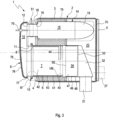
- An exhaust gas treatment device 1 which is intended for use in an exhaust system of an internal combustion engine, in particular a motor vehicle, can have a housing 2 which has a laterally circumferential jacket 3 and two end floors or end floors 4, 5, of which in Fig. 1 Only the one or first end floor 4 faces the viewer.
- the other or second end base 5 is arranged at the end of the housing 2 remote from the first end base 4.
- the exhaust gas treatment device 1 expediently equipped with at least one receiving tube 6.
- a receiving tube 6 is provided at the in the Fig. 1 and 3
- the respective receiving tube 6 penetrates the first end base 4 axially.
- the respective receiving tube 6 accommodates a particle filter 7.
- the respective particle filter 7 is inserted axially and from the outside, i.e. from a side facing away from the interior 23 of the housing 2, into an outlet end 8 of the receiving tube 6 which penetrates the first end base 4.
- the particle filter 7 is arranged coaxially with the receiving tube 6.
- a deflection housing 9 is also provided.
- the deflection housing 9 has at least one inlet 11 communicating with the deflection chamber 10 and at least one outlet 12 communicating with the deflection chamber 10.
- the deflection housing 9 is attached to the housing 2 of the exhaust gas treatment device 1, which can also be referred to below as the main housing 2.
- at least one fastening device 13 is used, which enables the respective inlet 11 of the deflection housing 9 to be releasably fastened to the respective outlet end 8 of the respective receiving tube 6.
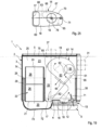
- the exhaust gas treatment device 1 shown here can also have a mixing housing 14 which is arranged in the main housing 2.
- the mixing housing 14 contains a mixing chamber 15 and has an inlet 16 which communicates with the mixing chamber 15 and an outlet 17 which also communicates with the mixing chamber 15. Both the inlet 16 and the outlet 17 pass through the first end base 4 of the main housing 2.
- the mixing chamber 14 can only be seen in physical contact with the main housing 2 in the area of an end face 18 facing the first base 4, while it is in Otherwise, it is spaced apart from the main housing 2, in particular from the jacket 3 and from the second end base 5.
- the dimensioning of the mixing housing 14 is expediently adapted to the dimensioning of the main housing 2 in such a way that a deflection region 19 which is remote from the inlet 16 in the mixing chamber 15 is further away from the first end floor 4 than from the second end floor 5.
- the mixing housing 14 extends from the first end floor 4 to the second end floor 5, but preferably without touching it. This gives the mixing chamber 15 a comparatively large length in the axial direction of the, in particular cylindrical or barrel-shaped, main housing 2.
- the outlet 17 of the mixing housing 14 opens into a deflection chamber 20, which can also be referred to below as a further deflection chamber 20.
- a deflection chamber 20 which can also be referred to below as a further deflection chamber 20.
- At least one inlet 21 of at least one SCR catalytic converter 22 also opens into this further deflection chamber 20.
- the respective inlet 21 of the SCR catalytic converter 22 also penetrates the first end base 4.
- the respective SCR catalytic converter 22 also extends inside 23 of the main housing 2.
- the exhaust gas treatment device 1 has two such SCR catalytic converters 22. It is clear that there can also be more or fewer SCR catalysts 22.
- the two SCR catalytic converters 22 are flowed through in parallel and open on the outlet side via a corresponding outlet 24 into the interior 23 or into a calming chamber 25 of the main housing 2, which is formed in the interior 23.
- the SCR catalytic converter 22 in the example has two SCR catalytic converter elements 26 which are arranged one behind the other, i.e. through which flow can flow in series.
- the main housing 2 has an outlet connection 27 in the usual way, which communicates with the calming chamber 25, for example.
- An intermediate floor 28 can also be arranged in the main housing 2, which separates the calming chamber 25 from an absorption chamber 29 in the interior 23, which in the example can be filled with a sound-absorbing material 30.
- the intermediate floor 28 is designed to be permeable to airborne sound. For example, it has a corresponding perforation.
- further sound attenuation measures can be provided in the exhaust gas treatment device 1.
- the main housing 2 is further equipped with an inlet port 31, which corresponds to Fig. 3 inside 23 is connected via a deflection shell 32 to an inlet 33 of an oxidation catalyst 34.
- the oxidation catalyst 34 is arranged upstream of the particle filter 7. If several particle filters 7 are accommodated in the main housing 2, a corresponding number of oxidation catalysts 34 are also provided, which are supplied with exhaust gas via a common inlet connection 31 or via separate inlet connections 31. It is also possible to provide a common oxidation catalyst 34 for several particle filters 7.
- the particle filter 7 has an outlet-side end section 35 facing the deflection housing 9, which is expediently configured so that it can be integrated into the fastening device 13. Said end section 35 is integrated into the fastening device 13 in such a way that an axial fixation of the particle filter 7 on the receiving tube 6 or at the inlet 11 of the deflection housing 9 and thus also an axial fixation of the particle filter 7 on the deflection housing 9 is formed. By loosening the fastening device 13, the axial fixation of the particle filter 7 is also removed, so that the particle filter 7 can be pulled axially out of the receiving tube 6 when the deflection housing 9 is removed. By installing the diverter housing 9 and by attaching the deflection housing 9 to the main housing 2, the respective particle filter 7 is also fixed in the intended relative position with the aid of the fastening device 13.
- the fastening device 13 is designed as a clamp connection.
- Fig. 7 a fastening device 13 designed as a screwed flange connection.
- the respective fastening device 13 comprises a first fastening flange 36 which is formed at the free end of the respective inlet 11.
- the fastening device 13 includes a second fastening flange 37, which is formed at the free outlet end 8 of the respective receiving tube 6.
- the outlet-side end section 35 of the particle filter 7 now has a collar 38 which projects outwards and is designed segmentally or preferably completely circumferentially.
- this collar 38 is arranged axially between the fastening flanges 36, 37 of the fastening device 13.
- the fastening device 13 is expediently configured in such a way that it enables axial tensioning of the collar 38 between the fastening flanges 36, 37.
- the respective fastening device 13 can be equipped with at least one seal 39 in order to improve the gas-tightness of the connection produced.
- one such seal 39 is provided, which rests axially directly on both fastening flanges 36, 37.
- the collar 38 rests directly on the fastening flanges 36, 37.
- the fastening flanges 36, 37 each being axially supported on the collar 38 via one of these seals 39 on sides facing away from one another.
- An embodiment in which the seals 39 are attached to the collar 38, for example by gluing or vulcanizing, is particularly useful. By changing the particle filter 7, the respective seal 39 can then be automatically replaced. In addition, assembly is simplified.
- the particle filter 7 In order to be able to replace the particle filter 7 easily, it is expediently equipped with a jacket 41 which is designed to be tubular and which accommodates at least one particle filter element 42.
- the particle filter element 42 is covered in the usual way by means of a bearing mat 43 and is thus positioned in the jacket 41.
- the aforementioned collar 38 is expediently formed integrally on this jacket 41 of the particle filter 7.
- FIG. 3 An inlet-side end section 40 of the particle filter 7, which is remote from the deflection housing 9, can be supported radially on the receiving tube 6 in such a way that said end section 40 is axially displaceable relative to the receiving tube 6.
- This axial displaceability of the inlet end section 40 can be realized in different ways.
- Fig. 8-13 Several alternative solutions are shown as examples.
- Fig. 8 An annular or ring segment-shaped bearing body 44 can be attached to the particle filter 7 or to its jacket 41, which can slide off the receiving tube 6.
- the bearing body 44 can be designed to be elastic and, for example, be formed by a completely circumferential or segmentally circumferential band or cushion made of wire mesh or bearing mat material.
- This elastic bearing body 44 can accordingly Fig. 9 be attached to the particle filter 7 or its jacket 41 and slide off the receiving tube 6. It is also possible, accordingly Fig. 12 to attach such an elastic bearing body 44 firmly to the receiving tube 6 so that the particle filter 7 or its jacket 41 can slide off it.
- a contour enabling storage is provided directly on the particle filter 7 or on its jacket 41 Fig. 10 or directly on the receiving tube 6 according to 11 and 13 shaped.
- Fig. 10 a cross-sectional expansion 45, which is formed directly on the jacket 41 of the particle filter 7 and which can be configured to be completely circumferential or segmentally circumferential.
- This cross-sectional expansion 45 can be seen to be supported directly on the receiving tube 6.
- a cross-sectional constriction 46 formed on the receiving tube 6 is provided, which is dimensioned such that direct radial contact with the particle filter 7 or with its jacket 41 occurs.
- This cross-sectional constriction 46 can also extend completely circumferentially or segmentally circumferentially in the circumferential direction.
- the in Fig. 11 shown linear support has an annular circumferential cross-sectional constriction 46
- the in Fig. 13 shown flat support indicates a point-wise or segment-wise circumferential cross-sectional constriction 46, which has several contact areas arranged at a distance in the circumferential direction.
- Fig. 3 shows a further special feature of the exhaust gas treatment device 1 presented here.
- the oxidation catalyst 34 comprises an oxidation catalyst element 47, which is arranged in a tubular jacket 48 and is positioned in the associated jacket 48 by means of a corresponding bearing mat 49.
- the jacket 48 of the oxidation catalyst 34 is axially extended on an outlet side 50 of the oxidation catalyst 34.
- This axial outlet-side extension of the jacket 48 of the oxidation catalytic converter 34 forms the receiving tube 6 in the embodiments shown here. This results in extreme simplification and weight savings when realizing the easy interchangeability of the particle filter 7.
- FIG. 3 are the outlet 12 of the deflection housing 9 and the inlet 16 of the mixing housing 14 connected to communicate with each other.
- a fastening device 51 should also be used for this connection, which makes it possible to releasably fasten the outlet 12 and the inlet 16 to one another.
- This further fastening device 51 can basically be the same type of fastening device 13 mentioned above. This is therefore preferably a clamp connection or a screwed flange connection.
- the Fig. 14-16 show different embodiments.
- the Fig. 14 and 15 each show a clamp connection, the respective clamp 52 being designed as a flat clamp 52, which only causes a radial compression of the pipe sections inserted coaxially into one another, namely on the one hand between the outlet 8 of the receiving tube 6 and the inlet 11 of the deflection housing 9 and on the other hand between the outlet 12 of the deflection housing 9 and the inlet 16 of the mixing housing 14.
- a configuration corresponding to this is preferred Fig. 15 , in which the respective clamp connection 13, 51 is designed as a V-clamp 53. Such a V-clamp 53 can be used accordingly Fig.
- 4-6 be equipped with a circumferential tension band 54 and with a V-profile 55, whereby axial compression of the fastening flanges 36, 37 can be achieved with the help of such a V-clamp 53, which can also be referred to as a V-band clamp.
- V-clamp 53 which can also be referred to as a V-band clamp.
- Tensioning devices 56 are indicated, which enable the respective clamp 53 to be tensioned in the usual way.
- Fig. 14 in the respective clamp 52 there is only one area 57, which is provided for arranging a suitable clamping device.
- FIG. 16 an embodiment in which the respective fastening device 13, 51 is designed as a screwed flange connection 58. Corresponding screws 59 are in Fig. 7 recognizable. From the Fig. 14-16 It can be seen that the fastening devices 13, 51 working with the V-clamps 53 are particularly compact in the axial direction. Fig. 3 indicates that the two fastening devices 13, 51 do not necessarily have to be configured identically.
- the fastening device 13 assigned to the particle filter 7 is designed as a V-clamp 53, while the fastening device 51 assigned to the mixing housing 14 is designed here as a flat clamp 52 as an example.
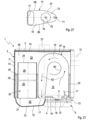
- At least one guide wall 60 can be arranged in the mixing housing 14.
- the embodiments of the Fig. 17 and 20-23 show only a single guide wall 60, while the embodiments of Fig. 18 and 19 additionally have a further guide wall 61.
- the respective guide wall 60, 61 forms a mixing section 62 within the mixing chamber 15, which is in the Fig. 17-23 is indicated by arrows.
- simple embodiments are also conceivable that do not require a guide wall 60, 61.
- an intermediate wall 63 is also arranged in the mixing housing 14, which can be seen in the associated side views of the Fig. 24 or 25 is easier to see.
- the respective intermediate wall 63 separates two levels from one another within the mixing chamber 15.
- the mixing section 62 extends through both levels.
- a section of the mixing section 62 which extends in the plane facing away from the viewer, is shown with broken arrows, while a section of the mixing section 62, which is located in the plane facing the viewer, is indicated with solid arrows. It can be seen that comparatively complex mixing sections 62 can be implemented.
- the exhaust gas flow is guided through the mixing housing 14 in such a way that at least a deflection of 180° is established between a flow direction at the inlet 16 and a flow direction at the outlet 17.
- a flow deflection of more than 180° is easily achieved.
- the exhaust gas flow is redirected three times by 180°, i.e. by around 540° in total.
- the intermediate wall 63 shown has at least one passage opening 64 through which the exhaust gas passes along the mixing section 62 from one level to the other level.
- the mixing housing 14 is expediently designed so that the inlet 16 communicates with one level, while the outlet 17 is communicatively connected to the other level.
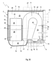
- the two guide walls 60, 61 are each equipped with a connecting opening 65 and 66, respectively.
- the guide walls 60, 61 are arranged within the mixing chamber 15 so that they divide the mixing section 62 into several sectors.
- the aforementioned connection openings 65, 66 now enable a communicating connection between successive sectors. As a result, the flow guidance can be improved and the mixing section 62 can be extended using simple means. It is clear that in a simple embodiment the mixing chamber 14 also works without a guide wall 60, 61 and without an intermediate wall 63.
- the mixing housing 14 is expediently designed to be gas-tight relative to the interior 23 of the main housing 2.
- the main housing 2 can be made from cheaper materials.
- leaks can be tolerated in the main housing 2, so that the main housing 2 can also be manufactured more cheaply.
- the mixing housing 14 has a housing body 67.
- the housing body 67 has the end face 18 already mentioned above, which faces the first end base 4 of the main housing 2.
- This end face 18 now has the inlet 16 and the outlet 17 of the mixing housing 14.
- the inlet 16 is designed as an inlet port which passes through an unspecified inlet opening of the first end base 4 of the main housing 2.
- said inlet opening can be provided with an outwardly projecting, ring-shaped collar.
- the outlet 17 can also be designed as an outlet connection, which passes through an unspecified outlet opening of the first end base 4 of the main housing 2.
- This outlet opening can also be provided with an outwardly projecting, ring-shaped collar.
- the connectors preferably extend parallel to one another.
- the housing body 67 can preferably be designed in a shell design and according to the illustrations Fig. 24-29 have an upper shell 68 and a lower shell 69. Furthermore, an end shell 70 forming the end face 18 can be provided as an additional component. Thanks to the proposed design, the mixing housing 14 can be manufactured particularly inexpensively and made gas-tight.
- the exhaust gas treatment device 1 shown here is in accordance with Fig. 17-23 and 24-29 are equipped with at least one metering device 71, with the help of which a liquid educt, namely preferably a reducing agent, can be introduced into the mixing chamber 15.
- a liquid educt namely preferably a reducing agent
- ammonia or urea or an aqueous urea solution can be mixed into the exhaust gas flow upstream of the SCR catalytic converter 22.
- the metering device 71 is expediently positioned so that the reducing agent is introduced virtually at the beginning of the mixing section 62.
- the metering device 71 is preferably positioned in such a way that it can introduce the reducing agent into the mixing chamber 15 in the area of the inlet 16 of the mixing housing 14.
- the metering device 71 is expediently attached to the first end plate 4, in such a way that it passes through this first end plate 4 and the mixing housing 14. In the example, the metering device 71 is positioned so that it penetrates the end face 18 or the end shell 70 of the housing body 68.
- Fig. 30 therefore shows examples of further positions that are suitable for arranging such a metering device.
- a deflection shell 72 can be attached to the first end base 4. Together with an area of the first end base 4 covered by the deflection shell 72, the deflection shell 72 delimits the further deflection chamber 20.
- This deflection shell 72 is dimensioned so that it covers the outlet 17 of the mixing housing 14 and the respective inlet 21 of the respective SCR catalytic converter 22.
- the deflection shell 72 is designed to be double-walled, which can be used to implement air gap insulation.
- a thermally insulating insulation material 73 can be introduced into the double wall of the deflection shell 72.
- the jacket 3 of the main housing 2 can be designed to be double-walled. This can be used to implement air gap insulation or to introduce a thermally insulating insulation material 74.
- the second end floor 5 can be designed to be double-walled for air gap insulation or for accommodating a thermally insulating insulation material 75.
- the deflection housing 9 comprises a cup-shaped shell body 76 and a lid or base 77, between which the deflection chamber 10 is delimited.
- the lid or base 77 has the respective inlet 11 and the respective outlet 12.
- the shell body 76 is in the example Fig. 3 designed to be double-walled and can accordingly form an air gap insulation or, as here, a receiving space for accommodating a thermally insulating insulation material 78.
- a metering device 79 or further metering device 79 can be provided, with the help of which a liquid educt, in particular a reducing agent, can also be introduced into the exhaust gas flow.
- This further metering device is arranged here on the deflection housing 9, in such a way that it can introduce the respective educt in the direction of the inlet 16 of the mixing housing 14.
- the metering device 79 is part of the scope of the deflection housing 9. In this configuration, the distance up to the inlet 16 or through the inlet 16 to the mixing chamber 15 or to the mixing section 62 is also added in order to extend this further.
Landscapes
- Engineering & Computer Science (AREA)
- Chemical & Material Sciences (AREA)
- Chemical Kinetics & Catalysis (AREA)
- Combustion & Propulsion (AREA)
- Mechanical Engineering (AREA)
- General Engineering & Computer Science (AREA)
- Health & Medical Sciences (AREA)
- Toxicology (AREA)
- Exhaust Gas After Treatment (AREA)
- Processes For Solid Components From Exhaust (AREA)
Description
Die vorliegende Erfindung betrifft eine Abgasbehandlungseinrichtung für eine Abgasanlage einer Brennkraftmaschine, insbesondere eines Kraftfahrzeugs.The present invention relates to an exhaust gas treatment device for an exhaust system of an internal combustion engine, in particular a motor vehicle.
Eine derartige Abgasbehandlungseinrichtung kann zumindest ein Partikelfilter enthalten, um im Abgas mitgeführte Partikel, insbesondere Ruß, herauszufiltern. Die herausgefilterten Partikel werden dabei in einem Partikelfilterelement des Partikelfilters eingelagert. Mit zunehmender Beladung sinkt die Speicherfähigkeit des Partikelfilters, während gleichzeitig sein Durchströmungswiderstand zunimmt. Dementsprechend werden Regenerationen durchgeführt, bei denen die Partikelbeladung abgebrannt wird. Da sich im Partikelfilter auch nicht abbrennbare Partikel einlagern, kommt es trotz Regenerationen allmählich zu einem Zusetzen des Partikelfilters, was dessen Speicherfähigkeit reduziert und dessen Durchströmungswiderstand erhöht. Über die vorgesehene Laufzeit einer Brennkraftmaschine kann es daher erforderlich sein, das Partikelfilter zu warten bzw. auszutauschen. Unerwünscht ist dabei, die komplette Abgasbehandlungseinrichtung auszutauschen. Vielmehr ist erwünscht, die Abgasbehandlungseinrichtung so auszugestalten, dass das Partikelfilter oder zumindest das jeweilige Partikelfilterelement mit möglichst geringem Aufwand zugänglich gemacht und ausgetauscht werden kann. Hierzu ist es üblich, ein Gehäuse der Abgasbehandlungseinrichtung so auszugestalten, dass es geöffnet werden kann. Zu diesem Zweck lassen sich zum Beispiel einzelne Bestandteile des Gehäuses lösbar aneinander befestigen. Denkbar sind beispielsweise Flanschbefestigungen, die jedoch ein erhöhtes Gewicht sowie einen vergleichsweise hohen Herstellungsaufwand bedeuten. Steckverbindungen scheiden quasi aus, da diese nach einer langen Verbindungszeit nicht mehr oder nur noch sehr schwer lösbar sind. Am besten scheinen sich Schellenverbindungen zu eignen.Such an exhaust gas treatment device can contain at least one particle filter in order to filter out particles, in particular soot, carried in the exhaust gas. The filtered out particles are stored in a particle filter element of the particle filter. As the load increases, the storage capacity of the particle filter decreases, while at the same time its flow resistance increases. Accordingly, regenerations are carried out in which the particle load is burned off. Since non-burnable particles are also stored in the particle filter, the particle filter gradually becomes clogged despite regeneration, which reduces its storage capacity and increases its flow resistance. It may therefore be necessary to maintain or replace the particle filter over the intended running time of an internal combustion engine. It is undesirable to replace the entire exhaust gas treatment device. Rather, it is desirable to design the exhaust gas treatment device in such a way that the particle filter or at least the respective particle filter element can be made accessible and replaced with as little effort as possible. For this purpose, it is common to design a housing of the exhaust gas treatment device so that it can be opened. For this purpose, for example, individual components of the housing can be releasably attached to one another. For example, flange fastenings are conceivable, but they mean increased weight and a comparatively high manufacturing effort. Plug-in connections are virtually eliminated because after a long connection time they can no longer be removed or can only be removed with great difficulty. Clamp connections seem to be the best.
Aus der
Aus der
Aus der
Die vorliegende Erfindung beschäftigt sich mit dem Problem, für eine Abgasbehandlungseinrichtung der eingangs genannten Art eine verbesserte Ausführungsform anzugeben, die sich insbesondere durch eine einfache Handhabung zum Wechseln des Partikelfilters auszeichnet.The present invention deals with the problem of providing an improved embodiment for an exhaust gas treatment device of the type mentioned, which is characterized in particular by easy handling for changing the particle filter.
Dieses Problem wird erfindungsgemäß durch den Gegenstand des unabhängigen Anspruchs gelöst. Vorteilhafte Ausführungsformen sind Gegenstand der abhängigen Ansprüche.This problem is solved according to the invention by the subject matter of the independent claim. Advantageous embodiments are the subject of the dependent claims.
Die Erfindung beruht auf dem allgemeinen Gedanken, in das Gehäuse der Abgasbehandlungseinrichtung zumindest ein Aufnahmerohr so einzubauen, dass es einen Endboden des insbesondere tonnenförmigen Gehäuses durchsetzt. In der Folge kann ein Partikelfilter, der seinerseits einen Mantel aufweist, in dem wenigstens ein Partikelfilterelement mittels einer Lagermatte umhüllt und lagepositioniert ist, axial in das Aufnahmerohr eingesetzt werden, ohne dass das Gehäuse selbst geöffnet werden muss. Zusätzlich wird die Abgasbehandlungseinrichtung mit einem Umlenkgehäuse ausgestattet, das im montierten Zustand die aus dem Partikelfilter bzw. aus dem Aufnahmerohr austretende Abgasströmung in einer darin enthaltenden Umlenkkammer zu einem Einlass des Gehäuses umlenkt, der ebenfalls den genannten Endboden des Gehäuses durchsetzt. Auf diese Weise kann das Abgas durch das externe Umlenkgehäuse aus dem eigentlichen Gehäuse der Abgasbehandlungseinrichtung ausgeführt, umgelenkt und wieder eingeführt werden. Im Inneren des Gehäuses der Abgasbehandlungseinrichtung kann sich dann optional eine weitere Behandlung der Abgase anschließen. Das genannte Umlenkgehäuse ist mittels wenigstens einer Befestigungseinrichtung lösbar an das Gehäuse angebaut, wobei die jeweilige Befestigungseinrichtung zumindest einen Einlass des Umlenkgehäuses mit einem Auslassende des Aufnahmerohrs lösbar verbindet.The invention is based on the general idea of installing at least one receiving tube in the housing of the exhaust gas treatment device in such a way that it passes through an end base of the barrel-shaped housing in particular. As a result, a particle filter, which in turn has a jacket in which at least one particle filter element is encased and positionally positioned by means of a bearing mat, can be inserted axially into the receiving tube without the housing itself having to be opened. In addition, the exhaust gas treatment device is equipped with a deflection housing which, in the assembled state, diverts the exhaust gas flow emerging from the particle filter or from the receiving pipe in a deflection chamber contained therein to an inlet of the housing, which also passes through the said end base of the housing. In this way, the exhaust gas can be led out of the actual housing of the exhaust gas treatment device through the external deflection housing, diverted and reintroduced. Further treatment of the exhaust gases can then optionally be carried out inside the housing of the exhaust gas treatment device. Said deflection housing is releasably attached to the housing by means of at least one fastening device, the respective fastening device releasably connecting at least one inlet of the deflection housing to an outlet end of the receiving tube.
Die vorgeschlagene Bauweise schafft eine ausreichende Zugänglichkeit zum Partikelfilter für Wartungszwecke, ohne dass hierzu das Gehäuse selbst geöffnet werden muss. Das lösbare Anbauen eines derartigen Umlenkgehäuses gestaltet sich vergleichsweise einfach und kostengünstig.The proposed design creates sufficient accessibility to the particle filter for maintenance purposes without the housing itself having to be opened. The detachable attachment of such a thing The deflection housing is comparatively simple and inexpensive.
Entsprechend einer vorteilhaften Ausführungsform kann ein auslassseitiger Endabschnitt des Partikelfilters, der dem Umlenkgehäuse zugewandt ist, so ausgestaltet sein, dass er in die Befestigungseinrichtung, die zum lösbaren Befestigen des Einlasses des Umlenkgehäuses am Auslassende des Aufnahmerohrs vorgesehen ist, so eingebunden werden kann, dass sich dadurch eine axiale Festlegung des Partikelfilters am Aufnahmerohr bzw. am Einlass des Umlenkgehäuses ergibt. Mit anderen Worten, die Befestigungseinrichtung, die zum Befestigen des Umlenkgehäuses am Gehäuse der Abgasbehandlungseinrichtung dient, erfüllt eine Doppelfunktion, da mit ihr gleichzeitig das in das Aufnahmerohr eingesetzte Partikelfilter axial fixiert wird. Hierdurch erleichtert sich die Montage und Demontage bzw. das Wechseln des Partikelfilters, da keine separate zusätzliche Befestigungseinrichtung betätigt werden muss, die zum separaten Fixieren des Partikelfilters vorgesehen sein könnte.According to an advantageous embodiment, an outlet-side end section of the particle filter, which faces the deflection housing, can be designed so that it can be integrated into the fastening device, which is provided for releasably attaching the inlet of the deflection housing to the outlet end of the receiving tube, in such a way that an axial fixation of the particle filter on the receiving pipe or at the inlet of the deflection housing results. In other words, the fastening device, which is used to fasten the deflection housing to the housing of the exhaust gas treatment device, fulfills a double function, since it simultaneously axially fixes the particle filter inserted into the receiving tube. This makes assembly and disassembly or changing of the particle filter easier, since no separate additional fastening device has to be operated, which could be provided for separately fixing the particle filter.
Entsprechend einer anderen vorteilhaften Ausführungsform kann ein einlassseitiger Endabschnitt des Partikelfilters, der vom Umlenkgehäuse abgewandt ist, axial verschiebbar am Aufnahmerohr radial abgestützt sein. Hierdurch kann das Partikelfilter im Bereich seines einlassseitigen Endabschnitts Relativbewegungen bezüglich des Aufnahmerohrs durchführen. Dies ist insbesondere im Hinblick auf thermische Dehnungseffekte von erhöhter Bedeutung. Im Bereich des einlassseitigen Endabschnitts führt die axial verschiebbare Abstützung zu einem Loslager des Partikelfilters im bzw. am Aufnahmerohr, während die am einlassseitigen Endabschnitt des Partikelfilters vorgesehene axiale Fixierung quasi ein Festlager zwischen Partikelfilter und Aufnahmerohr bildet. Diese Kombination ergibt eine sichere und stabile Abstützung bzw. Lagefixierung des Partikelfilters im Aufnahmerohr und ist außerdem weitgehend frei von thermischen Spannungen.According to another advantageous embodiment, an inlet-side end section of the particle filter, which faces away from the deflection housing, can be axially displaceably supported radially on the receiving tube. As a result, the particle filter can carry out relative movements with respect to the receiving tube in the area of its inlet end section. This is particularly important with regard to thermal expansion effects. In the area of the inlet-side end section, the axially displaceable support leads to a floating bearing of the particle filter in or on the receiving tube, while the axial fixation provided on the inlet-side end section of the particle filter essentially forms a fixed bearing between the particle filter and the receiving tube. This combination results in secure and stable support or fixation of the position of the particle filter in the receiving tube and is also largely free of thermal stresses.
Erfindungsgemäß ist außerdem vorgesehen, das Aufnahmerohr durch eine auslassseitige Verlängerung eines Mantels eines Oxidationskatalysators zu bilden, der stromauf des Partikelfilters im Gehäuse der Abgasbehandlungseinrichtung angeordnet ist. Besagter Mantel nimmt außerdem zumindest ein Oxidationskatalysatorelement auf. Somit erhält besagter Mantel des Oxidationskatalysators eine Doppelfunktion, da er einerseits das jeweilige Oxidationskatalysatorelement aufnimmt, während er andererseits das Aufnahmerohr zur Aufnahme des Partikelfilters bildet.According to the invention, it is also provided that the receiving tube is formed by an outlet-side extension of a jacket of an oxidation catalytic converter, which is arranged upstream of the particle filter in the housing of the exhaust gas treatment device. Said jacket also accommodates at least one oxidation catalyst element. Thus, said jacket of the oxidation catalyst has a dual function, since on the one hand it accommodates the respective oxidation catalyst element, while on the other hand it forms the receiving tube for receiving the particle filter.
Weitere wichtige Merkmale und Vorteile der Erfindung ergeben sich aus den Unteransprüchen, aus den Zeichnungen und aus der zugehörigen Figurenbeschreibung anhand der Zeichnungen.Further important features and advantages of the invention emerge from the subclaims, from the drawings and from the associated description of the figures based on the drawings.
Es versteht sich, dass die vorstehend genannten und die nachstehend noch zu erläuternden Merkmale nicht nur in der jeweils angegebenen Kombination, sondern auch in anderen Kombinationen oder in Alleinstellung verwendbar sind, ohne den Rahmen der vorliegenden Erfindung zu verlassen.It is understood that the features mentioned above and those to be explained below can be used not only in the combination specified in each case, but also in other combinations or alone, without departing from the scope of the present invention.
Bevorzugte Ausführungsbeispiele der Erfindung sind in den Zeichnungen dargestellt und werden in der nachfolgenden Beschreibung näher erläutert, wobei sich gleiche Bezugszeichen auf gleiche oder ähnliche oder funktional gleiche Bauteile beziehen.Preferred exemplary embodiments of the invention are shown in the drawings and are explained in more detail in the following description, with the same reference numbers referring to the same or similar or functionally the same components.
Es zeigen, jeweils schematisch
- Fig. 1
- eine axiale Ansicht einer Abgasbehandlungseinrichtung mit Umlenkgehäuse,
- Fig. 2
- eine axiale Ansicht eines Umlenkgehäuses einer anderen Ausführungsform,
- Fig. 3
- einen Längsschnitt der Abgasbehandlungseinrichtung entsprechend Schnittlinien III in
Fig. 1 , - Fig. 4-7
- vergrößerte Ansichten eines Details IV in
Fig. 3 , - Fig. 8-13
- vergrößerte Ansichten eines Details VIII aus
Fig. 3 , - Fig. 14-16
- Seitenansichten der Abgasbehandlungseinrichtung im Bereich des Umlenkgehäuses bei unterschiedlichen Ausführungsformen,
- Fig. 17
- einen Längsschnitt der Abgasbehandlungseinrichtung entsprechend Schnittlinien XVII in
Fig. 1 , - Fig. 18-23
- Schnittansichten wie in
Fig. 17 , jedoch bei unterschiedlichen Ausführungsformen eines Mischgehäuses, - Fig. 24-29
- axiale Ansichten des Mischgehäuses entsprechend den Ausführungsformen der
Fig. 18-23 , - Fig. 30
- eine weitere Schnittansicht wie in den
Fig. 17-23 zur Veranschaulichung verschiedener Einbaupositionen einer Zumesseinrichtung.
- Fig. 1
- an axial view of an exhaust gas treatment device with a deflection housing,
- Fig. 2
- an axial view of a deflection housing of another embodiment,
- Fig. 3
- a longitudinal section of the exhaust gas treatment device according to section lines III in
Fig. 1 , - Fig. 4-7
- enlarged views of a detail IV in
Fig. 3 , - Fig. 8-13
- enlarged views of a detail VIII
Fig. 3 , - Fig. 14-16
- Side views of the exhaust gas treatment device in the area of the deflection housing in different embodiments,
- Fig. 17
- a longitudinal section of the exhaust gas treatment device according to section lines XVII in
Fig. 1 , - Fig. 18-23
- Sectional views as in
Fig. 17 , but with different embodiments of a mixing housing, - Fig. 24-29
- Axial views of the mixing housing according to the embodiments of
Fig. 18-23 , - Fig. 30
- another sectional view like in the
Fig. 17-23 to illustrate different installation positions of a metering device.
Entsprechend
Entsprechend den
Im Beispiel ist außerdem ein Umlenkgehäuse 9 vorgesehen. Dieses enthält entsprechend
Zusätzlich oder alternativ kann die hier gezeigte Abgasbehandlungseinrichtung 1 außerdem ein Mischgehäuse 14 aufweisen, das im Hauptgehäuse 2 angeordnet ist. Das Mischgehäuse 14 enthält eine Mischkammer 15 und besitzt einen Einlass 16, der mit der Mischkammer 15 kommuniziert, sowie einen Auslass 17, der ebenfalls mit der Mischkammer 15 kommuniziert. Sowohl der Einlass 16 als auch der Auslass 17 durchsetzen den ersten Endboden 4 des Hauptgehäuses 2. Erkennbar ist bei den hier gezeigten Ausführungsformen die Mischkammer 14 nur im Bereich einer dem ersten Boden 4 zugewandten Stirnseite 18 in körperlichem Kontakt mit dem Hauptgehäuse 2, während es im Übrigen vom Hauptgehäuse 2, also insbesondere vom Mantel 3 und vom zweiten Endboden 5 beabstandet ist. Die Dimensionierung des Mischgehäuses 14 ist zweckmäßig so an die Dimensionierung des Hauptgehäuses 2 angepasst, dass ein in der Mischkammer 15 vom Einlass 16 entfernter Umlenkbereich 19 vom ersten Endboden 4 weiter entfernt ist als vom zweiten Endboden 5. Mit anderen Worten, das Mischgehäuse 14 erstreckt sich vom ersten Endboden 4 bis zum zweiten Endboden 5, jedoch vorzugsweise ohne diesen zu berühren. Hierdurch erhält die Mischkammer 15 eine vergleichsweise große Länge in axialer Richtung des, insbesondere zylindrischen oder tonnenförmigen, Hauptgehäuses 2.Additionally or alternatively, the exhaust
Der Auslass 17 des Mischgehäuses 14 mündet in eine Umlenkkammer 20 ein, die im Folgenden auch als weitere Umlenkkammer 20 bezeichnet werden kann. In diese weitere Umlenkkammer 20 mündet ferner zumindest ein Einlass 21 wenigstens eines SCR-Katalysators 22 ein. Der jeweilige Einlass 21 des SCR-Katalysators 22 durchdringt dabei ebenfalls den ersten Endboden 4. Der jeweilige SCR-Katalysator 22 erstreckt sich im Übrigen im Inneren 23 des Hauptgehäuses 2. Entsprechend
Das Hauptgehäuse 2 weist in üblicher Weise einen Auslassanschluss 27 auf, der zum Beispiel mit der Beruhigungskammer 25 kommuniziert. Im Hauptgehäuse 2 kann außerdem ein Zwischenboden 28 angeordnet sein, der im Inneren 23 die Beruhigungskammer 25 von einer Absorptionskammer 29 trennt, die im Beispiel mit einem schallabsorbierenden Material 30 gefüllt sein kann. Der Zwischenboden 28 ist für Luftschall durchlässig ausgestaltet. Beispielsweise besitzt er eine entsprechende Perforation. Darüber hinaus können weitere Schalldämpfungsmaßnahmen in der Abgasbehandlungseinrichtung 1 vorgesehen sein.The
Das Hauptgehäuse 2 ist ferner mit einem Einlassanschluss 31 ausgestattet, der entsprechend
Mit Bezug auf die
Bei den Ausführungsformen der
Die jeweilige Befestigungseinrichtung 13 kann mit wenigstens einer Dichtung 39 ausgestattet sein, um die Gasdichtigkeit der hergestellten Verbindung zu verbessern. Im Beispiel der
Um das Partikelfilter 7 vereinfacht auswechseln zu können, ist es zweckmäßig mit einem Mantel 41 ausgestattet, der rohrförmig konzipiert ist und der zumindest ein Partikelfilterelement 42 aufnimmt. Das Partikelfilterelement 42 ist dabei in üblicher Weise mittels einer Lagermatte 43 umhüllt und damit im Mantel 41 lagepositioniert. Zweckmäßig ist der zuvor genannte Bund 38 integral an diesem Mantel 41 des Partikelfilters 7 ausgeformt.In order to be able to replace the
Entsprechend
Entsprechend den
Bei den Ausführungsformen der
Entsprechend
Die
Schließlich zeigt
Entsprechend den
Bei den Ausführungsformen der
Auch die in
Die in den Ausführungsformen der
Zweckmäßig ist das Mischgehäuse 14 gegenüber dem Inneren 23 des Hauptgehäuses 2 gasdicht ausgestaltet. In der Folge kann das Hauptgehäuse 2 aus preiswerteren Materialien hergestellt werden. Ferner können beim Hauptgehäuse 2 Leckagen toleriert werden, so dass auch die Herstellung des Hauptgehäuses 2 preiswerter realisierbar ist.The mixing
Bei den hier gezeigten Ausführungsformen besitzt das Mischgehäuse 14 einen Gehäusekörper 67. Der Gehäusekörper 67 weist die weiter oben bereits erwähnte Stirnseite 18 auf, die dem ersten Endboden 4 des Hauptgehäuses 2 zugewandt ist. Diese Stirnseite 18 weist nun den Einlass 16 und den Auslass 17 des Mischgehäuses 14 auf. Entsprechend den hier gezeigten, bevorzugten Ausführungsformen ist der Einlass 16 als Einlassstutzen ausgestaltet, der eine nicht näher bezeichnete Einlassöffnung des ersten Endbodens 4 des Hauptgehäuses 2 durchsetzt. Exemplarisch kann besagte Einlassöffnung mit einem nach außen abstehenden, ringförmig umlaufenden Kragen versehen sein. Analog dazu kann auch der Auslass 17 als Auslassstutzen ausgestaltet sein, der eine nicht näher bezeichnete Auslassöffnung des ersten Endbodens 4 des Hauptgehäuses 2 durchsetzt. Auch diese Auslassöffnung kann mit einem nach außen abstehenden, ringförmig umlaufenden Kragen versehen sein. Die Stutzen erstrecken sich bevorzugt parallel zueinander.In the embodiments shown here the mixing
Der Gehäusekörper 67 kann vorzugsweise in Schalenbauweise konzipiert sein und gemäß den Darstellungen der
Die hier gezeigte Abgasbehandlungseinrichtung 1 ist entsprechend den
Grundsätzlich ist die Anordnung bzw. Positionierung der Zumesseinrichtung 71 bezüglich des Mischgehäuses 14 quasi beliebig wählbar.
Zur Realisierung der weiteren Umlenkkammer 20 kann am ersten Endboden 4 eine Umlenkschale 72 angebracht sein. Zusammen mit einem von der Umlenkschale 72 überdeckten Bereich des ersten Endbodens 4 begrenzt die Umlenkschale 72 die weitere Umlenkkammer 20. Entsprechend
Die Umlenkschale 72 ist im Beispiel doppelwandig konzipiert, was zur Realisierung einer Luftspaltisolierung genutzt werden kann. Ebenso kann in die Doppelwand der Umlenkschale 72 ein thermisch isolierendes Isolationsmaterial 73 eingebracht sein. Der Mantel 3 des Hauptgehäuses 2 kann doppelwandig konzipiert sein. Dies kann zur Realisierung einer Luftspaltisolierung oder zum Einbringen eines thermisch isolierenden Isolationsmaterials 74 genutzt werden. Der zweite Endboden 5 kann doppelwandig konzipiert sein für eine Luftspaltisolierung oder für die Aufnahme eines thermisch isolierenden Isolationsmaterials 75.In the example, the
Entsprechend
Entsprechend
Claims (13)
- An exhaust gas treatment system for an exhaust gas system of an internal combustion engine, in particular a motor vehicle,- comprising a housing (2) with a laterally circulating shell (3) and two end-side end bottoms (4, 5),- wherein at least one receiver pipe (6) is provided which penetrates through the one or first end bottom (4) and in the outlet end (8) of which a particle filter (7) is axially inserted from the outside,- wherein the particle filter (7) has a shell (41), in which at least one particle filter element (42) is encased by means of a mounting mat (43) and is positioned therein,- wherein a deflection housing (9) is provided that contains a deflection chamber (10) that has at least one inlet (11) in communication with the deflection chamber (10) and at least one outlet (12) in communication with the deflection chamber (10),- wherein at least one fixing device (13) for detachably fixing the respective inlet (11) to the respective outlet (8) of the receiver pipe (6) is provided,- wherein the receiver pipe (6) is formed by an outlet-side extension of a shell (48) of an oxidising catalytic convertor (34) that has at least one oxidising catalytic convertor element (47) provided in the shell (48).
- The exhaust gas treatment device as claimed in claim 1, characterized in that an outlet-side end section (35) of the particle filter (7), which faces the deflection housing (9), is integrated in the respective fixing device (13) for axially fixing the particle filter (7) to the respective receiver pipe (6) and/or to the respective inlet (12).
- The exhaust gas treatment device as claimed in any one of claims 1 to 2, characterized in that the respective fixing device (13) is designed as a clamp connection (52, 53) or as a screwed flange connection (58).
- The exhaust gas treatment device as claimed in any one of claims 1 to 3, characterized in that- the respective fixing device (13) has a first fixing flange (36) formed at the free end of the respective inlet (11) and a second fixing flange (37) formed at the free outlet end (8) of the respective receiver pipe (6),- the outlet-side end section (35) of the particle filter (7) has a collar (38) that protrudes outwards and extends around either in segments or completely, which is provided axially between the fixing flanges (36, 37).
- The exhaust gas treatment device as claimed in claim 4, characterized in that the collar (38) is formed on the shell (41) of the particle filter (7).
- The exhaust gas treatment system as claimed in claim 4 or 5, characterized in that- the collar (38) is axially clamped between the fixing flanges (36, 37),
and/or- the fixing flanges (36, 37) are axially supported on each other via a seal (39) or on the collar (38) via two seals (39). - The exhaust gas treatment system as claimed in any one of claims 1 to 6, characterized in that an inlet-side end section (40) of the particle filter (7) is radially supported in an axially displaceable manner on the receiver pipe (6).
- The exhaust gas treatment system as claimed in claim 7, characterized in that- the inlet-side end section (40) is supported on the receiver pipe (6) via a support body (44) that is fixed to the particle filter (7) or on the receiver pipe (6) and extends around either in segments or completely,
or- the inlet-side end section (40) has a cross-sectional widening (45) that extends around in segments or completely, which is directly supported on the receiver pipe (6), or in that the receiver pipe (6) has, in the region of the inlet-side end section (40), a cross-sectional narrowing (46) that extends around either in segments or completely, which is directly supported on the particle filter (7). - The exhaust gas treatment system as claimed in any one of claims 1 to 8,
characterized in that a mixing housing (14) is provided in the housing (2), which has a mixing chamber (15), an inlet (16) that penetrates through the first end bottom (4) and is in communication with the mixing chamber (15), and an outlet (17) that penetrates through the first end bottom (4) and is in communication with the mixing chamber (15), and the deflection section (19) removed from the first end bottom (4) is removed from the first end bottom (4) further than from the other or second end bottom (5). - The exhaust gas treatment system as claimed in claim 9, characterized in that at least one guiding wall (60, 61) is provided in the mixing housing (14), which forms in the mixing chamber (15) a mixing section (62) that extends from the inlet (16) via the deflection section (19) to the outlet (17).
- The exhaust gas treatment system as claimed in claim 10, characterized in that an intermediate wall (63) is provided in the mixing housing (14), which separates two planes from each other in the mixing chamber (15), in which the mixing section (62) extends.
- The exhaust gas treatment system as claimed in any one of claims 9 to 11,
characterized in that- an exhaust gas flow passed through the mixing housing (14) is deflected from the inlet (16) to the outlet (17) by more than 180° or by at least 540°,
and/or- the inlet (16) of the mixing housing (14) is detachably fixed to the outlet (12) of the deflection housing (9) using a same or a different fixing unit (51), and/or - a deflection tray (72) is fixed on the outside to the first end bottom (4), which tray delimits a further deflection chamber (20), into which the outlet (17) of the mixing housing (14) opens and into which at least one inlet (21) of at least one SCR catalytic convertor (22) opens, which penetrates through the first end bottom (4). - The exhaust gas treatment system as claimed in any one of claims 9 to 12,
characterized in that at least one dosing unit (71, 79) for introducing a reducing agent into the mixing chamber (15) is provided.
Applications Claiming Priority (1)
| Application Number | Priority Date | Filing Date | Title |
|---|---|---|---|
| DE200910014435 DE102009014435A1 (en) | 2009-03-26 | 2009-03-26 | Exhaust gas treatment device |
Publications (3)
| Publication Number | Publication Date |
|---|---|
| EP2233708A1 EP2233708A1 (en) | 2010-09-29 |
| EP2233708B1 EP2233708B1 (en) | 2016-07-27 |
| EP2233708B2 true EP2233708B2 (en) | 2023-10-18 |
Family
ID=42084019
Family Applications (1)
| Application Number | Title | Priority Date | Filing Date |
|---|---|---|---|
| EP10152663.0A Active EP2233708B2 (en) | 2009-03-26 | 2010-02-04 | Exhaust treatment device |
Country Status (3)
| Country | Link |
|---|---|
| US (3) | US8621853B2 (en) |
| EP (1) | EP2233708B2 (en) |
| DE (1) | DE102009014435A1 (en) |
Families Citing this family (28)
| Publication number | Priority date | Publication date | Assignee | Title |
|---|---|---|---|---|
| DE102010034743A1 (en) * | 2010-08-19 | 2012-02-23 | J. Eberspächer GmbH & Co. KG | Exhaust gas purification device, exhaust system, removal process |
| US8561395B2 (en) | 2011-03-03 | 2013-10-22 | Tenneco Automotive Operating Company Inc. | Poka-yoke mounting system for an exhaust treatment device |
| US9174818B1 (en) | 2011-11-29 | 2015-11-03 | Brunswick Corporation | Marine engines and exhaust systems for marine engines having a catalyst for treating exhaust |
| US9903251B1 (en) | 2011-11-29 | 2018-02-27 | Brunswick Corporation | Outboard motors and exhaust systems for outboard motors having an exhaust conduit supported inside the V-shape |
| DE102012207960B3 (en) | 2012-05-11 | 2013-08-08 | Eberspächer Exhaust Technology GmbH & Co. KG | particulate Filter |
| DE102012214285A1 (en) * | 2012-08-10 | 2014-02-13 | Friedrich Boysen Gmbh & Co. Kg | Device for guiding a gas flow |
| DE102013219640A1 (en) | 2013-09-27 | 2015-04-02 | Eberspächer Exhaust Technology GmbH & Co. KG | Exhaust gas treatment device |
| WO2015187162A1 (en) * | 2014-06-05 | 2015-12-10 | Faurecia Emissions Control Technologies, Usa, Llc | Insulated cover for mixer assembly |
| GB2586428B (en) * | 2014-10-22 | 2021-08-25 | Cummins Emission Solutions Inc | Diesel exhaust fluid mixing body using variable cross-section switchback arrangement |
| DE102015100552B3 (en) * | 2015-01-15 | 2016-06-16 | Eberspächer Exhaust Technology GmbH & Co. KG | Support ring for an exhaust system |
| CN105649723A (en) * | 2015-09-18 | 2016-06-08 | 湖北农谷环保科技有限公司 | Double-cylinder automobile noise reduction catalyst converter |
| SG11201808182UA (en) * | 2016-04-07 | 2018-10-30 | Entegris Inc | Gas filter |
| JP6682972B2 (en) * | 2016-04-14 | 2020-04-15 | いすゞ自動車株式会社 | Exhaust gas purification device for internal combustion engine |
| US9758228B1 (en) | 2016-07-01 | 2017-09-12 | Brunswick Corporation | Exhaust manifolds for outboard marine engines |
| JP6771099B2 (en) * | 2017-04-28 | 2020-10-21 | 東京濾器株式会社 | Exhaust purification device |
| WO2018198344A1 (en) * | 2017-04-28 | 2018-11-01 | 東京濾器株式会社 | Exhaust gas purification device |
| CN107780998B (en) * | 2017-10-18 | 2021-01-15 | 潍柴动力股份有限公司 | Universal integrated DOC-DPF-SCR post-treatment device |
| US10329978B1 (en) | 2018-02-13 | 2019-06-25 | Brunswick Corporation | High temperature exhaust systems for marine propulsion devices |
| US10287948B1 (en) | 2018-04-23 | 2019-05-14 | Faurecia Emissions Control Technologies, Usa, Llc | High efficiency mixer for vehicle exhaust system |
| US10316721B1 (en) | 2018-04-23 | 2019-06-11 | Faurecia Emissions Control Technologies, Usa, Llc | High efficiency mixer for vehicle exhaust system |
| US10787946B2 (en) | 2018-09-19 | 2020-09-29 | Faurecia Emissions Control Technologies, Usa, Llc | Heated dosing mixer |
| EP3757361A1 (en) | 2019-06-28 | 2020-12-30 | Dinex A/S | Filter device |
| EP3770396B1 (en) | 2019-07-25 | 2024-06-26 | RTA GmbH | Exhaust gas aftertreatment device for an exhaust system of a motor vehicle and motor vehicle comprising such an exhaust gas aftertreatment device |
| EP3792463B1 (en) * | 2019-09-16 | 2023-05-31 | Roth Technik Austria Gesellschaft Mit Beschränkter Haftung | Exhaust gas aftertreatment device with exhaust gas aftertreatment devices replaceable by releasing a non-destructively releasable connection |
| EP4063627B1 (en) | 2021-03-25 | 2024-12-11 | Volvo Truck Corporation | An exhaust aftertreatment arrangement for converting nox emissions |
| EP4063625B1 (en) * | 2021-03-25 | 2024-11-13 | Volvo Truck Corporation | An exhaust aftertreatment unit for cleaning exhaust gases |
| EP4112893B1 (en) * | 2021-07-01 | 2025-02-26 | Volvo Truck Corporation | An exhaust aftertreatment unit for cleaning exhaust gases |
| DE102023110142A1 (en) * | 2023-04-21 | 2024-10-24 | Purem GmbH | Modular exhaust gas treatment system |
Citations (5)
| Publication number | Priority date | Publication date | Assignee | Title |
|---|---|---|---|---|
| US20030159436A1 (en) † | 2002-02-27 | 2003-08-28 | Foster Michael Ralph | Diesel particulate filter ash removal |
| DE102005002289A1 (en) † | 2005-01-17 | 2006-07-27 | J. Eberspächer GmbH & Co. KG | Exhaust gas treatment system |
| EP1701011A1 (en) † | 2003-11-27 | 2006-09-13 | Hino Motors, Ltd. | Exhaust emission control device |
| DE102007006804A1 (en) † | 2007-02-12 | 2008-08-14 | Arvinmeritor Emissions Technologies Gmbh | Exhaust gas cleaning device, particularly for exhaust gas plant of internal combustion engine, has outer housing, which comprises two housing parts |
| WO2009019922A1 (en) † | 2007-08-06 | 2009-02-12 | Bosch Corporation | Exhaust purification apparatus |
Family Cites Families (78)
| Publication number | Priority date | Publication date | Assignee | Title |
|---|---|---|---|---|
| US1315904A (en) * | 1919-09-09 | Stovepipe | ||
| US3210102A (en) * | 1964-07-22 | 1965-10-05 | Joslin Alvin Earl | Pipe coupling having a deformed inner lock |
| US3724878A (en) * | 1971-03-24 | 1973-04-03 | J Ford | Flexible connector |
| DE2243251B2 (en) * | 1972-09-02 | 1976-01-02 | Paul Gillet Gmbh, 6732 Edenkoben | Device for cleaning exhaust gases from internal combustion engines |
| US3817714A (en) * | 1972-10-10 | 1974-06-18 | Corning Glass Works | Catalytic converter |
| JPS5375614U (en) * | 1976-11-29 | 1978-06-23 | ||
| JPS53141166A (en) * | 1977-05-16 | 1978-12-08 | Chuo Hatsujo Kk | Honey comb catalytic converter and assembly method therefor |
| US4239733A (en) * | 1979-04-16 | 1980-12-16 | General Motors Corporation | Catalytic converter having a monolith with support and seal means therefor |
| US4248833A (en) * | 1979-08-28 | 1981-02-03 | Chuo Hatsujo Kabushiki Kaisha | Exhaust gas purifier system for internal combustion engine |
| US4342373A (en) * | 1981-03-17 | 1982-08-03 | Tenneco Inc. | Muffler with three part welded joint |
| JPS6131131Y2 (en) | 1981-03-26 | 1986-09-10 | ||
| JPS5941621A (en) * | 1982-08-31 | 1984-03-07 | Toyota Motor Corp | Monolith catalytic converter |
| US4462812A (en) | 1982-12-08 | 1984-07-31 | General Motors Corporation | Ceramic monolith particulate trap including filter support |
| DE3608371A1 (en) | 1986-03-13 | 1987-09-17 | Fev Forsch Energietech Verbr | HOUSING FOR EXHAUST GAS TREATMENT SYSTEMS, ESPECIALLY FOR PARTICLE FILTER SYSTEMS |
| US4782661A (en) * | 1987-02-13 | 1988-11-08 | General Motors Corporation | Mat support/substrate subassembly and method of making a catalytic converter therewith |
| US5190732A (en) * | 1988-10-11 | 1993-03-02 | Emitec Gesellschaft Fur Emissionstechnologie Mbh | Catalyst with a double casing system |
| JP2580353Y2 (en) * | 1991-09-03 | 1998-09-10 | 臼井国際産業株式会社 | Automotive catalytic converter |
| DE4134466A1 (en) | 1991-10-18 | 1993-04-22 | Eberspaecher J | DOUBLE-WALLED AIR-INSULATED TUBE FOR EXHAUST SYSTEMS IN VEHICLES |
| US5293743A (en) * | 1992-05-21 | 1994-03-15 | Arvin Industries, Inc. | Low thermal capacitance exhaust processor |
| US5709415A (en) * | 1995-09-11 | 1998-01-20 | Xyzyx International Corporation | Quick connect disconnect coupling |
| US6923942B1 (en) * | 1997-05-09 | 2005-08-02 | 3M Innovative Properties Company | Compressible preform insulating liner |
| JP2957163B1 (en) * | 1998-05-28 | 1999-10-04 | 株式会社三五 | Exhaust system parts and manufacturing method |
| DE19834822A1 (en) | 1998-08-01 | 2000-02-03 | Stihl Maschf Andreas | Exhaust silencer with a catalytic converter |
| EP0992659B1 (en) * | 1998-10-05 | 2007-05-02 | Scambia Industrial Developments Aktiengesellschaft | Exhaust pipe element and method for producing an exhaust pipe element |
| US6162403A (en) * | 1998-11-02 | 2000-12-19 | General Motors Corporation | Spin formed vacuum bottle catalytic converter |
| FR2787137B1 (en) | 1998-12-14 | 2001-02-23 | Ecia Equip Composants Ind Auto | EXHAUST GAS DEPOLLUTION DEVICE |
| US6908595B1 (en) * | 1999-01-22 | 2005-06-21 | Benteler Automotive Corporation | Vacuum-insulated exhaust treatment devices, such as catalytic converters, with passive controls |
| DE60018794T2 (en) * | 1999-12-09 | 2006-03-30 | Eminox Ltd., Gainsborough | DEVICE FOR TREATING GASSTROM |
| DE50110583D1 (en) * | 2000-04-14 | 2006-09-14 | Eberspaecher J Gmbh & Co | Exhaust silencer in multi-chamber design |
| US6877780B2 (en) * | 2000-06-23 | 2005-04-12 | Breeze-Torca Products, Llc | Clamp for joining tubular bodies |
| DE10042542A1 (en) | 2000-08-30 | 2002-03-14 | Eberspaecher J Gmbh & Co | Exhaust gas cleaning system for motor vehicles, in particular diesel commercial vehicles |
| DE10046610C1 (en) * | 2000-09-20 | 2002-04-25 | Emitec Emissionstechnologie | Solid-lot storage of a catalyst carrier body |
| EP1366274A1 (en) | 2001-02-07 | 2003-12-03 | Paulo T. Lage | Exhaust processor with renewable particulate eliminator |
| FR2821117B1 (en) * | 2001-02-21 | 2004-04-23 | Faurecia Ind | CLEANABLE DEVICE FOR CLEANING EXHAUST GASES FROM AN ENGINE |
| DE10140228A1 (en) | 2001-08-16 | 2003-03-06 | Gillet Heinrich Gmbh | Reversible connector for internal combustion engine exhaust systems, has pipe connector for attachment to second housing, fitting over first housing, band clamped over butted connector/ring |
| DE10144613A1 (en) | 2001-09-11 | 2003-04-03 | Eberspaecher J Gmbh & Co | Exhaust gas purification arrangement of a motor vehicle exhaust system |
| US7028132B2 (en) * | 2001-09-29 | 2006-04-11 | Hewlett-Packard Development Company, L.P. | Distributed peer-to-peer communication for interconnect busses of a computer system |
| DE20200599U1 (en) | 2002-01-16 | 2002-06-20 | Heinrich Gillet GmbH & Co. KG, 67480 Edenkoben | Device for cleaning the exhaust gases from internal combustion engines |
| GB2387339B (en) * | 2002-04-13 | 2004-02-25 | Eminox Ltd | Gas treatment apparatus |
| DE10243644B4 (en) | 2002-09-19 | 2008-09-11 | Roth-Technik Austria Ges.M.B.H. | Detachable connection of profile components |
| US7332137B2 (en) * | 2003-03-24 | 2008-02-19 | Delphi Technologies, Inc. | End cone assembly, exhaust emission control device and method of making thereof |
| US7369019B2 (en) * | 2003-12-18 | 2008-05-06 | Altierre Corporation | RF backscatter transmission with zero DC power consumption |
| JP3715981B2 (en) | 2004-03-25 | 2005-11-16 | 日産ディーゼル工業株式会社 | Silencer with exhaust purification function |
| DE102004037480A1 (en) * | 2004-08-03 | 2006-03-02 | Zeuna-Stärker GmbH & Co KG | A vehicle exhaust gas purification device and method of manufacturing the same |
| WO2006029199A1 (en) | 2004-09-08 | 2006-03-16 | Donaldson Company, Inc. | Joint for an engine exhaust system component |
| WO2006029201A1 (en) * | 2004-09-08 | 2006-03-16 | Donaldson Company, Inc. | Construction for an engine exhaust system component |
| JP3715985B1 (en) * | 2004-10-29 | 2005-11-16 | 日産ディーゼル工業株式会社 | Liquid reducing agent injection nozzle structure |
| US20060157296A1 (en) * | 2004-11-09 | 2006-07-20 | Belisle John I | Engine exhaust system with water entrapment |
| DE202005001616U1 (en) | 2005-02-01 | 2005-05-25 | Roth-Technik Austria Ges.M.B.H. | Detachable connection of profile components with centering rings |
| DE102005019182B4 (en) | 2005-04-25 | 2019-05-16 | Faurecia Emissions Control Technologies, Germany Gmbh | Exhaust gas purification device and method for its production |
| DE102005025045A1 (en) * | 2005-05-30 | 2006-12-14 | J. Eberspächer GmbH & Co. KG | exhaust system |
| DE102005041733A1 (en) | 2005-09-02 | 2007-03-08 | Daimlerchrysler Ag | Exhaust gas after treatment device for e.g. diesel engine, has treatment section arranged between fluid injection unit and silencer in common housing and comprising baffle for exhaust gas mass flow with fluid, e.g. urea water solution |
| US7503956B2 (en) * | 2005-10-25 | 2009-03-17 | Caterpillar Inc. | Exhaust treatment device with adjustable retention collar |
| GB0525375D0 (en) * | 2005-12-14 | 2006-01-18 | 3M Innovative Properties Co | Mounting mat for a pollution control device |
| DE102006023854B4 (en) | 2006-05-19 | 2008-03-27 | J. Eberspächer GmbH & Co. KG | Exhaust after-treatment device for an internal combustion engine |
| US7650965B2 (en) * | 2006-06-09 | 2010-01-26 | Emcon Technologies Llc | Exhaust system |
| DE102006029337A1 (en) | 2006-06-23 | 2007-12-27 | Gat Katalysatoren Gmbh | Sound absorbing device for use in e.g. lorry, has diesel particulate filter detachably held in housing that is formed in opened and closed manner, where filter with opened housing is taken out from housing and into housing |
| US7611561B2 (en) * | 2006-07-20 | 2009-11-03 | Benteler Automotive Corporation | Diesel exhaust filter construction |
| DE202006012530U1 (en) * | 2006-08-16 | 2006-11-16 | Heinrich Gillet Gmbh | Sound attenuating system incorporates means in at least two releasably joined modules for treatment of exhaust gases of internal combustion engines of commercial vehicles |
| US7550024B2 (en) * | 2006-09-07 | 2009-06-23 | Cummins Filtration Ip, Inc. | Serviceable exhaust aftertreatment assembly and method |
| US7614215B2 (en) | 2006-09-18 | 2009-11-10 | Cummins Filtration Ip, Inc. | Exhaust treatment packaging apparatus, system, and method |
| FR2908831B1 (en) | 2006-11-22 | 2011-11-04 | Renault Sas | ARRANGEMENT FOR THE ASSEMBLY OF AN EXHAUST GAS DERIVATION DRIVE HAVING AN END-OF-END FRONTIER CONDUCTED BY A DELEGATION DEVICE |
| JP4972391B2 (en) * | 2006-12-13 | 2012-07-11 | 新光電気工業株式会社 | Package with shield case and method of manufacturing package with shield case |
| JP4928304B2 (en) | 2007-02-23 | 2012-05-09 | 日野自動車株式会社 | Exhaust purification device |
| JP4886547B2 (en) | 2007-02-23 | 2012-02-29 | 日野自動車株式会社 | Exhaust purification device |
| DE202007004230U1 (en) | 2007-03-22 | 2008-07-31 | Heinrich Gillet Gmbh | exhaust system |
| WO2008128370A1 (en) * | 2007-04-20 | 2008-10-30 | Tehag Ag | Device and method for connecting housing sections of soot particle filters |
| US7567817B2 (en) * | 2007-05-14 | 2009-07-28 | Geo2 Technologies, Inc. | Method and apparatus for an extruded ceramic biosoluble fiber substrate |
| JP5132187B2 (en) | 2007-05-18 | 2013-01-30 | Udトラックス株式会社 | Exhaust purification device |
| US8230678B2 (en) | 2007-06-21 | 2012-07-31 | Daimler Trucks North America Llc | Treatment of diesel engine exhaust |
| JP2009018480A (en) * | 2007-07-11 | 2009-01-29 | Seiko Epson Corp | Line printer |
| DE202007010435U1 (en) | 2007-07-26 | 2007-10-25 | Heinrich Gillet Gmbh | Exhaust system for commercial vehicles |
| DE102007062662A1 (en) * | 2007-12-24 | 2009-06-25 | J. Eberspächer GmbH & Co. KG | Sliding seat and exhaust treatment device |
| DE102007062663A1 (en) * | 2007-12-24 | 2009-06-25 | J. Eberspächer GmbH & Co. KG | Sliding seat and pipe arrangement and exhaust treatment device |
| JP5033736B2 (en) * | 2008-08-08 | 2012-09-26 | 株式会社小松製作所 | Exhaust gas purification device |
| JP5390281B2 (en) * | 2009-07-02 | 2014-01-15 | ヤンマー株式会社 | Exhaust gas purification device |
| US8609030B2 (en) * | 2011-03-04 | 2013-12-17 | Tenneco Automotive Operating Company Inc. | Exhaust aftertreatment device with integrated shell and baffle |
| US8776509B2 (en) * | 2011-03-09 | 2014-07-15 | Tenneco Automotive Operating Company Inc. | Tri-flow exhaust treatment device with reductant mixing tube |
-
2009
- 2009-03-26 DE DE200910014435 patent/DE102009014435A1/en active Pending
-
2010
- 2010-02-04 EP EP10152663.0A patent/EP2233708B2/en active Active
- 2010-03-25 US US12/731,432 patent/US8621853B2/en active Active
-
2013
- 2013-11-27 US US14/092,311 patent/US9003782B2/en active Active
-
2014
- 2014-10-23 US US14/521,784 patent/US10253670B2/en active Active
Patent Citations (5)
| Publication number | Priority date | Publication date | Assignee | Title |
|---|---|---|---|---|
| US20030159436A1 (en) † | 2002-02-27 | 2003-08-28 | Foster Michael Ralph | Diesel particulate filter ash removal |
| EP1701011A1 (en) † | 2003-11-27 | 2006-09-13 | Hino Motors, Ltd. | Exhaust emission control device |
| DE102005002289A1 (en) † | 2005-01-17 | 2006-07-27 | J. Eberspächer GmbH & Co. KG | Exhaust gas treatment system |
| DE102007006804A1 (en) † | 2007-02-12 | 2008-08-14 | Arvinmeritor Emissions Technologies Gmbh | Exhaust gas cleaning device, particularly for exhaust gas plant of internal combustion engine, has outer housing, which comprises two housing parts |
| WO2009019922A1 (en) † | 2007-08-06 | 2009-02-12 | Bosch Corporation | Exhaust purification apparatus |
Also Published As
| Publication number | Publication date |
|---|---|
| EP2233708A1 (en) | 2010-09-29 |
| US20100242450A1 (en) | 2010-09-30 |
| US20140086802A1 (en) | 2014-03-27 |
| US9003782B2 (en) | 2015-04-14 |
| US10253670B2 (en) | 2019-04-09 |
| US20150040525A1 (en) | 2015-02-12 |
| EP2233708B1 (en) | 2016-07-27 |
| DE102009014435A1 (en) | 2010-10-14 |
| US8621853B2 (en) | 2014-01-07 |
Similar Documents
| Publication | Publication Date | Title |
|---|---|---|
| EP2233708B2 (en) | Exhaust treatment device | |
| EP2233709B1 (en) | Exhaust treatment device | |
| DE102005002289B4 (en) | Exhaust gas treatment system | |
| DE10356000B4 (en) | Silencer with integrated catalytic converter | |
| EP2075425B1 (en) | Exhaust gas treatment device with pipe assembly and sliding seat | |
| DE102013210799B4 (en) | Exhaust system of an internal combustion engine | |
| EP2116699B1 (en) | Exhaust gas treatment device | |
| EP2075426B1 (en) | Sliding fit and exhaust gas treatment device | |
| DE112008002531B4 (en) | aftertreatment system | |
| DE102006024778B3 (en) | Static mixer for exhaust system of internal combustion engine, has flow conducting surfaces arranged at web materials so that surfaces are arranged with cells at their diverting side and extend in direction of flow in tube | |
| DE102012218565B4 (en) | Exhaust system with line element | |
| EP2853705B2 (en) | Exhaust gas treatment device | |
| EP3365540B1 (en) | Exhaust gas purification system and internal combustion engine with exhaust gas purification system | |
| DE102008046222B4 (en) | Exhaust aftertreatment system | |
| DE102012207960B3 (en) | particulate Filter | |
| DE102009024534A1 (en) | exhaust gas cleaning device | |
| EP4086439B1 (en) | Exhaust gas treatment module | |
| EP2461887B1 (en) | Filter device and use of a wound filter element | |
| EP3704360B1 (en) | Exhaust gas system for compact and efficient aftertreatment and sound damping of the exhaust gas | |
| DE102012205350A1 (en) | Device for cleaning the exhaust gas of an internal combustion engine | |
| DE102011085941B4 (en) | Mixing and / or evaporation device | |
| DE102006038204B4 (en) | Inlet funnel for an exhaust gas treatment device | |
| DE29512732U1 (en) | Silencer for the exhaust system of an internal combustion engine | |
| DE102013022009A1 (en) | Apparatus for aftertreatment of exhaust gases of an internal combustion engine | |
| EP4183986A1 (en) | Exhaust gas system |
Legal Events
| Date | Code | Title | Description |
|---|---|---|---|
| PUAI | Public reference made under article 153(3) epc to a published international application that has entered the european phase |
Free format text: ORIGINAL CODE: 0009012 |
|
| AK | Designated contracting states |
Kind code of ref document: A1 Designated state(s): AT BE BG CH CY CZ DE DK EE ES FI FR GB GR HR HU IE IS IT LI LT LU LV MC MK MT NL NO PL PT RO SE SI SK SM TR |
|
| AX | Request for extension of the european patent |
Extension state: AL BA RS |
|
| 17P | Request for examination filed |
Effective date: 20110329 |
|
| RAP1 | Party data changed (applicant data changed or rights of an application transferred) |
Owner name: EBERSPAECHER EXHAUST TECHNOLOGY GMBH & CO. KG |
|
| TPAC | Observations filed by third parties |
Free format text: ORIGINAL CODE: EPIDOSNTIPA |
|
| 17Q | First examination report despatched |
Effective date: 20141127 |
|
| TPAC | Observations filed by third parties |
Free format text: ORIGINAL CODE: EPIDOSNTIPA |
|
| GRAP | Despatch of communication of intention to grant a patent |
Free format text: ORIGINAL CODE: EPIDOSNIGR1 |
|
| RIC1 | Information provided on ipc code assigned before grant |
Ipc: F01N 13/02 20100101ALN20160223BHEP Ipc: F01N 3/28 20060101ALI20160223BHEP Ipc: B01D 46/00 20060101ALI20160223BHEP Ipc: F01N 13/18 20100101ALI20160223BHEP Ipc: F01N 3/021 20060101AFI20160223BHEP Ipc: F01N 13/00 20100101ALI20160223BHEP Ipc: F01N 3/08 20060101ALI20160223BHEP Ipc: F01N 3/20 20060101ALI20160223BHEP Ipc: F01N 1/08 20060101ALN20160223BHEP |
|
| INTG | Intention to grant announced |
Effective date: 20160322 |
|
| GRAS | Grant fee paid |
Free format text: ORIGINAL CODE: EPIDOSNIGR3 |
|
| GRAA | (expected) grant |
Free format text: ORIGINAL CODE: 0009210 |
|
| AK | Designated contracting states |
Kind code of ref document: B1 Designated state(s): AT BE BG CH CY CZ DE DK EE ES FI FR GB GR HR HU IE IS IT LI LT LU LV MC MK MT NL NO PL PT RO SE SI SK SM TR |
|
| REG | Reference to a national code |
Ref country code: GB Ref legal event code: FG4D Free format text: NOT ENGLISH |
|
| REG | Reference to a national code |
Ref country code: CH Ref legal event code: EP |
|
| REG | Reference to a national code |
Ref country code: AT Ref legal event code: REF Ref document number: 815993 Country of ref document: AT Kind code of ref document: T Effective date: 20160815 |
|
| REG | Reference to a national code |
Ref country code: IE Ref legal event code: FG4D Free format text: LANGUAGE OF EP DOCUMENT: GERMAN |
|
| REG | Reference to a national code |
Ref country code: DE Ref legal event code: R096 Ref document number: 502010012075 Country of ref document: DE |
|
| REG | Reference to a national code |
Ref country code: SE Ref legal event code: TRGR |
|
| REG | Reference to a national code |
Ref country code: LT Ref legal event code: MG4D |
|
| REG | Reference to a national code |
Ref country code: NL Ref legal event code: MP Effective date: 20160727 |
|
| PG25 | Lapsed in a contracting state [announced via postgrant information from national office to epo] |
Ref country code: IS Free format text: LAPSE BECAUSE OF FAILURE TO SUBMIT A TRANSLATION OF THE DESCRIPTION OR TO PAY THE FEE WITHIN THE PRESCRIBED TIME-LIMIT Effective date: 20161127 Ref country code: LT Free format text: LAPSE BECAUSE OF FAILURE TO SUBMIT A TRANSLATION OF THE DESCRIPTION OR TO PAY THE FEE WITHIN THE PRESCRIBED TIME-LIMIT Effective date: 20160727 Ref country code: HR Free format text: LAPSE BECAUSE OF FAILURE TO SUBMIT A TRANSLATION OF THE DESCRIPTION OR TO PAY THE FEE WITHIN THE PRESCRIBED TIME-LIMIT Effective date: 20160727 Ref country code: NO Free format text: LAPSE BECAUSE OF FAILURE TO SUBMIT A TRANSLATION OF THE DESCRIPTION OR TO PAY THE FEE WITHIN THE PRESCRIBED TIME-LIMIT Effective date: 20161027 Ref country code: NL Free format text: LAPSE BECAUSE OF FAILURE TO SUBMIT A TRANSLATION OF THE DESCRIPTION OR TO PAY THE FEE WITHIN THE PRESCRIBED TIME-LIMIT Effective date: 20160727 Ref country code: IT Free format text: LAPSE BECAUSE OF FAILURE TO SUBMIT A TRANSLATION OF THE DESCRIPTION OR TO PAY THE FEE WITHIN THE PRESCRIBED TIME-LIMIT Effective date: 20160727 Ref country code: FI Free format text: LAPSE BECAUSE OF FAILURE TO SUBMIT A TRANSLATION OF THE DESCRIPTION OR TO PAY THE FEE WITHIN THE PRESCRIBED TIME-LIMIT Effective date: 20160727 |
|
| REG | Reference to a national code |
Ref country code: FR Ref legal event code: PLFP Year of fee payment: 8 |
|
| PG25 | Lapsed in a contracting state [announced via postgrant information from national office to epo] |
Ref country code: PT Free format text: LAPSE BECAUSE OF FAILURE TO SUBMIT A TRANSLATION OF THE DESCRIPTION OR TO PAY THE FEE WITHIN THE PRESCRIBED TIME-LIMIT Effective date: 20161128 Ref country code: GR Free format text: LAPSE BECAUSE OF FAILURE TO SUBMIT A TRANSLATION OF THE DESCRIPTION OR TO PAY THE FEE WITHIN THE PRESCRIBED TIME-LIMIT Effective date: 20161028 Ref country code: PL Free format text: LAPSE BECAUSE OF FAILURE TO SUBMIT A TRANSLATION OF THE DESCRIPTION OR TO PAY THE FEE WITHIN THE PRESCRIBED TIME-LIMIT Effective date: 20160727 Ref country code: ES Free format text: LAPSE BECAUSE OF FAILURE TO SUBMIT A TRANSLATION OF THE DESCRIPTION OR TO PAY THE FEE WITHIN THE PRESCRIBED TIME-LIMIT Effective date: 20160727 Ref country code: LV Free format text: LAPSE BECAUSE OF FAILURE TO SUBMIT A TRANSLATION OF THE DESCRIPTION OR TO PAY THE FEE WITHIN THE PRESCRIBED TIME-LIMIT Effective date: 20160727 |
|
| REG | Reference to a national code |
Ref country code: DE Ref legal event code: R026 Ref document number: 502010012075 Country of ref document: DE |
|
| PG25 | Lapsed in a contracting state [announced via postgrant information from national office to epo] |
Ref country code: EE Free format text: LAPSE BECAUSE OF FAILURE TO SUBMIT A TRANSLATION OF THE DESCRIPTION OR TO PAY THE FEE WITHIN THE PRESCRIBED TIME-LIMIT Effective date: 20160727 Ref country code: RO Free format text: LAPSE BECAUSE OF FAILURE TO SUBMIT A TRANSLATION OF THE DESCRIPTION OR TO PAY THE FEE WITHIN THE PRESCRIBED TIME-LIMIT Effective date: 20160727 |
|
| PLBI | Opposition filed |
Free format text: ORIGINAL CODE: 0009260 |
|
| PLBI | Opposition filed |
Free format text: ORIGINAL CODE: 0009260 |
|
| 26 | Opposition filed |
Opponent name: MAN TRUCK & BUS AG Effective date: 20170420 |
|
| PG25 | Lapsed in a contracting state [announced via postgrant information from national office to epo] |
Ref country code: DK Free format text: LAPSE BECAUSE OF FAILURE TO SUBMIT A TRANSLATION OF THE DESCRIPTION OR TO PAY THE FEE WITHIN THE PRESCRIBED TIME-LIMIT Effective date: 20160727 Ref country code: SM Free format text: LAPSE BECAUSE OF FAILURE TO SUBMIT A TRANSLATION OF THE DESCRIPTION OR TO PAY THE FEE WITHIN THE PRESCRIBED TIME-LIMIT Effective date: 20160727 Ref country code: SK Free format text: LAPSE BECAUSE OF FAILURE TO SUBMIT A TRANSLATION OF THE DESCRIPTION OR TO PAY THE FEE WITHIN THE PRESCRIBED TIME-LIMIT Effective date: 20160727 Ref country code: BG Free format text: LAPSE BECAUSE OF FAILURE TO SUBMIT A TRANSLATION OF THE DESCRIPTION OR TO PAY THE FEE WITHIN THE PRESCRIBED TIME-LIMIT Effective date: 20161027 Ref country code: CZ Free format text: LAPSE BECAUSE OF FAILURE TO SUBMIT A TRANSLATION OF THE DESCRIPTION OR TO PAY THE FEE WITHIN THE PRESCRIBED TIME-LIMIT Effective date: 20160727 Ref country code: BE Free format text: LAPSE BECAUSE OF NON-PAYMENT OF DUE FEES Effective date: 20170228 |
|
| PLAX | Notice of opposition and request to file observation + time limit sent |
Free format text: ORIGINAL CODE: EPIDOSNOBS2 |
|
| 26 | Opposition filed |
Opponent name: ROTH-TECHNIK AUSTRIA GESELLSCHAFT M.B.H. Effective date: 20170426 Opponent name: FRIEDRICH BOYSEN GMBH & CO. KG Effective date: 20170427 |
|
| REG | Reference to a national code |
Ref country code: DE Ref legal event code: R082 Ref document number: 502010012075 Country of ref document: DE Representative=s name: RLTG RUTTENSPERGER LACHNIT TROSSIN GOMOLL PATE, DE Ref country code: DE Ref legal event code: R082 Ref document number: 502010012075 Country of ref document: DE Representative=s name: RUTTENSPERGER LACHNIT TROSSIN GOMOLL PATENT- U, DE Ref country code: DE Ref legal event code: R082 Ref document number: 502010012075 Country of ref document: DE Representative=s name: RUTTENSPERGER LACHNIT TROSSIN GOMOLL, PATENT- , DE |
|
| PG25 | Lapsed in a contracting state [announced via postgrant information from national office to epo] |
Ref country code: SI Free format text: LAPSE BECAUSE OF FAILURE TO SUBMIT A TRANSLATION OF THE DESCRIPTION OR TO PAY THE FEE WITHIN THE PRESCRIBED TIME-LIMIT Effective date: 20160727 |
|
| PG25 | Lapsed in a contracting state [announced via postgrant information from national office to epo] |
Ref country code: MC Free format text: LAPSE BECAUSE OF FAILURE TO SUBMIT A TRANSLATION OF THE DESCRIPTION OR TO PAY THE FEE WITHIN THE PRESCRIBED TIME-LIMIT Effective date: 20160727 |
|
| REG | Reference to a national code |
Ref country code: CH Ref legal event code: PL |
|
| PLBB | Reply of patent proprietor to notice(s) of opposition received |
Free format text: ORIGINAL CODE: EPIDOSNOBS3 |
|
| GBPC | Gb: european patent ceased through non-payment of renewal fee |
Effective date: 20170204 |
|
| PG25 | Lapsed in a contracting state [announced via postgrant information from national office to epo] |
Ref country code: CH Free format text: LAPSE BECAUSE OF NON-PAYMENT OF DUE FEES Effective date: 20170228 Ref country code: LI Free format text: LAPSE BECAUSE OF NON-PAYMENT OF DUE FEES Effective date: 20170228 |
|
| REG | Reference to a national code |
Ref country code: IE Ref legal event code: MM4A |
|
| PG25 | Lapsed in a contracting state [announced via postgrant information from national office to epo] |
Ref country code: LU Free format text: LAPSE BECAUSE OF NON-PAYMENT OF DUE FEES Effective date: 20170204 |
|
| REG | Reference to a national code |
Ref country code: BE Ref legal event code: MM Effective date: 20170228 |
|
| REG | Reference to a national code |
Ref country code: FR Ref legal event code: PLFP Year of fee payment: 9 |
|
| PG25 | Lapsed in a contracting state [announced via postgrant information from national office to epo] |
Ref country code: GB Free format text: LAPSE BECAUSE OF NON-PAYMENT OF DUE FEES Effective date: 20170204 Ref country code: IE Free format text: LAPSE BECAUSE OF NON-PAYMENT OF DUE FEES Effective date: 20170204 |
|
| REG | Reference to a national code |
Ref country code: AT Ref legal event code: MM01 Ref document number: 815993 Country of ref document: AT Kind code of ref document: T Effective date: 20170204 |
|
| PG25 | Lapsed in a contracting state [announced via postgrant information from national office to epo] |
Ref country code: AT Free format text: LAPSE BECAUSE OF NON-PAYMENT OF DUE FEES Effective date: 20170204 |
|
| REG | Reference to a national code |
Ref country code: DE Ref legal event code: R082 Ref document number: 502010012075 Country of ref document: DE Representative=s name: RUTTENSPERGER LACHNIT TROSSIN GOMOLL PATENT- U, DE Ref country code: DE Ref legal event code: R082 Ref document number: 502010012075 Country of ref document: DE Representative=s name: RUTTENSPERGER LACHNIT TROSSIN GOMOLL, PATENT- , DE |
|
| PG25 | Lapsed in a contracting state [announced via postgrant information from national office to epo] |
Ref country code: MT Free format text: LAPSE BECAUSE OF FAILURE TO SUBMIT A TRANSLATION OF THE DESCRIPTION OR TO PAY THE FEE WITHIN THE PRESCRIBED TIME-LIMIT Effective date: 20160727 |
|
| APAH | Appeal reference modified |
Free format text: ORIGINAL CODE: EPIDOSCREFNO |
|
| APBM | Appeal reference recorded |
Free format text: ORIGINAL CODE: EPIDOSNREFNO |
|
| APBP | Date of receipt of notice of appeal recorded |
Free format text: ORIGINAL CODE: EPIDOSNNOA2O |
|
| APBM | Appeal reference recorded |
Free format text: ORIGINAL CODE: EPIDOSNREFNO |
|
| APBP | Date of receipt of notice of appeal recorded |
Free format text: ORIGINAL CODE: EPIDOSNNOA2O |
|
| APBQ | Date of receipt of statement of grounds of appeal recorded |
Free format text: ORIGINAL CODE: EPIDOSNNOA3O |
|
| PG25 | Lapsed in a contracting state [announced via postgrant information from national office to epo] |
Ref country code: HU Free format text: LAPSE BECAUSE OF FAILURE TO SUBMIT A TRANSLATION OF THE DESCRIPTION OR TO PAY THE FEE WITHIN THE PRESCRIBED TIME-LIMIT; INVALID AB INITIO Effective date: 20100204 |
|
| PLAB | Opposition data, opponent's data or that of the opponent's representative modified |
Free format text: ORIGINAL CODE: 0009299OPPO |
|
| R26 | Opposition filed (corrected) |
Opponent name: MAN TRUCK & BUS SE Effective date: 20170420 |
|
| PG25 | Lapsed in a contracting state [announced via postgrant information from national office to epo] |
Ref country code: CY Free format text: LAPSE BECAUSE OF NON-PAYMENT OF DUE FEES Effective date: 20160727 |
|
| PG25 | Lapsed in a contracting state [announced via postgrant information from national office to epo] |
Ref country code: MK Free format text: LAPSE BECAUSE OF FAILURE TO SUBMIT A TRANSLATION OF THE DESCRIPTION OR TO PAY THE FEE WITHIN THE PRESCRIBED TIME-LIMIT Effective date: 20160727 |
|
| PG25 | Lapsed in a contracting state [announced via postgrant information from national office to epo] |
Ref country code: TR Free format text: LAPSE BECAUSE OF FAILURE TO SUBMIT A TRANSLATION OF THE DESCRIPTION OR TO PAY THE FEE WITHIN THE PRESCRIBED TIME-LIMIT Effective date: 20160727 |
|
| PLAB | Opposition data, opponent's data or that of the opponent's representative modified |
Free format text: ORIGINAL CODE: 0009299OPPO |
|
| R26 | Opposition filed (corrected) |
Opponent name: MAN TRUCK & BUS SE Effective date: 20170420 |
|
| REG | Reference to a national code |
Ref country code: DE Ref legal event code: R082 Ref document number: 502010012075 Country of ref document: DE Representative=s name: RUTTENSPERGER LACHNIT TROSSIN GOMOLL, PATENT- , DE Ref country code: DE Ref legal event code: R081 Ref document number: 502010012075 Country of ref document: DE Owner name: PUREM GMBH, DE Free format text: FORMER OWNER: EBERSPAECHER EXHAUST TECHNOLOGY GMBH & CO. KG, 66539 NEUNKIRCHEN, DE |
|
| RAP2 | Party data changed (patent owner data changed or rights of a patent transferred) |
Owner name: PUREM GMBH |
|
| APBU | Appeal procedure closed |
Free format text: ORIGINAL CODE: EPIDOSNNOA9O |
|
| P01 | Opt-out of the competence of the unified patent court (upc) registered |
Effective date: 20230502 |
|
| PUAH | Patent maintained in amended form |
Free format text: ORIGINAL CODE: 0009272 |
|
| STAA | Information on the status of an ep patent application or granted ep patent |
Free format text: STATUS: PATENT MAINTAINED AS AMENDED |
|
| 27A | Patent maintained in amended form |
Effective date: 20231018 |
|
| AK | Designated contracting states |
Kind code of ref document: B2 Designated state(s): AT BE BG CH CY CZ DE DK EE ES FI FR GB GR HR HU IE IS IT LI LT LU LV MC MK MT NL NO PL PT RO SE SI SK SM TR |
|
| REG | Reference to a national code |
Ref country code: DE Ref legal event code: R102 Ref document number: 502010012075 Country of ref document: DE |
|
| REG | Reference to a national code |
Ref country code: SE Ref legal event code: RPEO |
|
| PGFP | Annual fee paid to national office [announced via postgrant information from national office to epo] |
Ref country code: DE Payment date: 20250218 Year of fee payment: 16 |
|
| PGFP | Annual fee paid to national office [announced via postgrant information from national office to epo] |
Ref country code: SE Payment date: 20250219 Year of fee payment: 16 |
|
| PGFP | Annual fee paid to national office [announced via postgrant information from national office to epo] |
Ref country code: FR Payment date: 20250220 Year of fee payment: 16 |