DE102015100552B3 - Support ring for an exhaust system - Google Patents
Support ring for an exhaust system Download PDFInfo
- Publication number
- DE102015100552B3 DE102015100552B3 DE102015100552.2A DE102015100552A DE102015100552B3 DE 102015100552 B3 DE102015100552 B3 DE 102015100552B3 DE 102015100552 A DE102015100552 A DE 102015100552A DE 102015100552 B3 DE102015100552 B3 DE 102015100552B3
- Authority
- DE
- Germany
- Prior art keywords
- support
- support ring
- arrangement
- ring according
- leg
- Prior art date
- Legal status (The legal status is an assumption and is not a legal conclusion. Google has not performed a legal analysis and makes no representation as to the accuracy of the status listed.)
- Active
Links
Images


Classifications
-
- F—MECHANICAL ENGINEERING; LIGHTING; HEATING; WEAPONS; BLASTING
- F01—MACHINES OR ENGINES IN GENERAL; ENGINE PLANTS IN GENERAL; STEAM ENGINES
- F01N—GAS-FLOW SILENCERS OR EXHAUST APPARATUS FOR MACHINES OR ENGINES IN GENERAL; GAS-FLOW SILENCERS OR EXHAUST APPARATUS FOR INTERNAL-COMBUSTION ENGINES
- F01N13/00—Exhaust or silencing apparatus characterised by constructional features
- F01N13/18—Construction facilitating manufacture, assembly, or disassembly
- F01N13/1805—Fixing exhaust manifolds, exhaust pipes or pipe sections to each other, to engine or to vehicle body
-
- F—MECHANICAL ENGINEERING; LIGHTING; HEATING; WEAPONS; BLASTING
- F01—MACHINES OR ENGINES IN GENERAL; ENGINE PLANTS IN GENERAL; STEAM ENGINES
- F01N—GAS-FLOW SILENCERS OR EXHAUST APPARATUS FOR MACHINES OR ENGINES IN GENERAL; GAS-FLOW SILENCERS OR EXHAUST APPARATUS FOR INTERNAL-COMBUSTION ENGINES
- F01N3/00—Exhaust or silencing apparatus having means for purifying, rendering innocuous, or otherwise treating exhaust
- F01N3/08—Exhaust or silencing apparatus having means for purifying, rendering innocuous, or otherwise treating exhaust for rendering innocuous
- F01N3/10—Exhaust or silencing apparatus having means for purifying, rendering innocuous, or otherwise treating exhaust for rendering innocuous by thermal or catalytic conversion of noxious components of exhaust
- F01N3/24—Exhaust or silencing apparatus having means for purifying, rendering innocuous, or otherwise treating exhaust for rendering innocuous by thermal or catalytic conversion of noxious components of exhaust characterised by constructional aspects of converting apparatus
- F01N3/28—Construction of catalytic reactors
- F01N3/2839—Arrangements for mounting catalyst support in housing, e.g. with means for compensating thermal expansion or vibration
- F01N3/2842—Arrangements for mounting catalyst support in housing, e.g. with means for compensating thermal expansion or vibration specially adapted for monolithic supports, e.g. of honeycomb type
-
- F—MECHANICAL ENGINEERING; LIGHTING; HEATING; WEAPONS; BLASTING
- F01—MACHINES OR ENGINES IN GENERAL; ENGINE PLANTS IN GENERAL; STEAM ENGINES
- F01N—GAS-FLOW SILENCERS OR EXHAUST APPARATUS FOR MACHINES OR ENGINES IN GENERAL; GAS-FLOW SILENCERS OR EXHAUST APPARATUS FOR INTERNAL-COMBUSTION ENGINES
- F01N13/00—Exhaust or silencing apparatus characterised by constructional features
- F01N13/08—Other arrangements or adaptations of exhaust conduits
-
- F—MECHANICAL ENGINEERING; LIGHTING; HEATING; WEAPONS; BLASTING
- F01—MACHINES OR ENGINES IN GENERAL; ENGINE PLANTS IN GENERAL; STEAM ENGINES
- F01N—GAS-FLOW SILENCERS OR EXHAUST APPARATUS FOR MACHINES OR ENGINES IN GENERAL; GAS-FLOW SILENCERS OR EXHAUST APPARATUS FOR INTERNAL-COMBUSTION ENGINES
- F01N3/00—Exhaust or silencing apparatus having means for purifying, rendering innocuous, or otherwise treating exhaust
- F01N3/02—Exhaust or silencing apparatus having means for purifying, rendering innocuous, or otherwise treating exhaust for cooling, or for removing solid constituents of, exhaust
- F01N3/021—Exhaust or silencing apparatus having means for purifying, rendering innocuous, or otherwise treating exhaust for cooling, or for removing solid constituents of, exhaust by means of filters
- F01N3/0211—Arrangements for mounting filtering elements in housing, e.g. with means for compensating thermal expansion or vibration
-
- F—MECHANICAL ENGINEERING; LIGHTING; HEATING; WEAPONS; BLASTING
- F01—MACHINES OR ENGINES IN GENERAL; ENGINE PLANTS IN GENERAL; STEAM ENGINES
- F01N—GAS-FLOW SILENCERS OR EXHAUST APPARATUS FOR MACHINES OR ENGINES IN GENERAL; GAS-FLOW SILENCERS OR EXHAUST APPARATUS FOR INTERNAL-COMBUSTION ENGINES
- F01N3/00—Exhaust or silencing apparatus having means for purifying, rendering innocuous, or otherwise treating exhaust
- F01N3/08—Exhaust or silencing apparatus having means for purifying, rendering innocuous, or otherwise treating exhaust for rendering innocuous
- F01N3/10—Exhaust or silencing apparatus having means for purifying, rendering innocuous, or otherwise treating exhaust for rendering innocuous by thermal or catalytic conversion of noxious components of exhaust
- F01N3/18—Exhaust or silencing apparatus having means for purifying, rendering innocuous, or otherwise treating exhaust for rendering innocuous by thermal or catalytic conversion of noxious components of exhaust characterised by methods of operation; Control
- F01N3/20—Exhaust or silencing apparatus having means for purifying, rendering innocuous, or otherwise treating exhaust for rendering innocuous by thermal or catalytic conversion of noxious components of exhaust characterised by methods of operation; Control specially adapted for catalytic conversion
-
- F—MECHANICAL ENGINEERING; LIGHTING; HEATING; WEAPONS; BLASTING
- F01—MACHINES OR ENGINES IN GENERAL; ENGINE PLANTS IN GENERAL; STEAM ENGINES
- F01N—GAS-FLOW SILENCERS OR EXHAUST APPARATUS FOR MACHINES OR ENGINES IN GENERAL; GAS-FLOW SILENCERS OR EXHAUST APPARATUS FOR INTERNAL-COMBUSTION ENGINES
- F01N3/00—Exhaust or silencing apparatus having means for purifying, rendering innocuous, or otherwise treating exhaust
- F01N3/08—Exhaust or silencing apparatus having means for purifying, rendering innocuous, or otherwise treating exhaust for rendering innocuous
- F01N3/10—Exhaust or silencing apparatus having means for purifying, rendering innocuous, or otherwise treating exhaust for rendering innocuous by thermal or catalytic conversion of noxious components of exhaust
- F01N3/24—Exhaust or silencing apparatus having means for purifying, rendering innocuous, or otherwise treating exhaust for rendering innocuous by thermal or catalytic conversion of noxious components of exhaust characterised by constructional aspects of converting apparatus
- F01N3/28—Construction of catalytic reactors
- F01N3/2839—Arrangements for mounting catalyst support in housing, e.g. with means for compensating thermal expansion or vibration
- F01N3/2853—Arrangements for mounting catalyst support in housing, e.g. with means for compensating thermal expansion or vibration using mats or gaskets between catalyst body and housing
- F01N3/2867—Arrangements for mounting catalyst support in housing, e.g. with means for compensating thermal expansion or vibration using mats or gaskets between catalyst body and housing the mats or gaskets being placed at the front or end face of catalyst body
-
- F—MECHANICAL ENGINEERING; LIGHTING; HEATING; WEAPONS; BLASTING
- F16—ENGINEERING ELEMENTS AND UNITS; GENERAL MEASURES FOR PRODUCING AND MAINTAINING EFFECTIVE FUNCTIONING OF MACHINES OR INSTALLATIONS; THERMAL INSULATION IN GENERAL
- F16L—PIPES; JOINTS OR FITTINGS FOR PIPES; SUPPORTS FOR PIPES, CABLES OR PROTECTIVE TUBING; MEANS FOR THERMAL INSULATION IN GENERAL
- F16L3/00—Supports for pipes, cables or protective tubing, e.g. hangers, holders, clamps, cleats, clips, brackets
- F16L3/08—Supports for pipes, cables or protective tubing, e.g. hangers, holders, clamps, cleats, clips, brackets substantially surrounding the pipe, cable or protective tubing
- F16L3/10—Supports for pipes, cables or protective tubing, e.g. hangers, holders, clamps, cleats, clips, brackets substantially surrounding the pipe, cable or protective tubing divided, i.e. with two members engaging the pipe, cable or protective tubing
- F16L3/1058—Supports for pipes, cables or protective tubing, e.g. hangers, holders, clamps, cleats, clips, brackets substantially surrounding the pipe, cable or protective tubing divided, i.e. with two members engaging the pipe, cable or protective tubing one member being flexible or elastic
-
- F—MECHANICAL ENGINEERING; LIGHTING; HEATING; WEAPONS; BLASTING
- F01—MACHINES OR ENGINES IN GENERAL; ENGINE PLANTS IN GENERAL; STEAM ENGINES
- F01N—GAS-FLOW SILENCERS OR EXHAUST APPARATUS FOR MACHINES OR ENGINES IN GENERAL; GAS-FLOW SILENCERS OR EXHAUST APPARATUS FOR INTERNAL-COMBUSTION ENGINES
- F01N2350/00—Arrangements for fitting catalyst support or particle filter element in the housing
- F01N2350/02—Fitting ceramic monoliths in a metallic housing
- F01N2350/06—Fitting ceramic monoliths in a metallic housing with means preventing gas flow by-pass or leakage
-
- Y—GENERAL TAGGING OF NEW TECHNOLOGICAL DEVELOPMENTS; GENERAL TAGGING OF CROSS-SECTIONAL TECHNOLOGIES SPANNING OVER SEVERAL SECTIONS OF THE IPC; TECHNICAL SUBJECTS COVERED BY FORMER USPC CROSS-REFERENCE ART COLLECTIONS [XRACs] AND DIGESTS
- Y02—TECHNOLOGIES OR APPLICATIONS FOR MITIGATION OR ADAPTATION AGAINST CLIMATE CHANGE
- Y02A—TECHNOLOGIES FOR ADAPTATION TO CLIMATE CHANGE
- Y02A50/00—TECHNOLOGIES FOR ADAPTATION TO CLIMATE CHANGE in human health protection, e.g. against extreme weather
- Y02A50/20—Air quality improvement or preservation, e.g. vehicle emission control or emission reduction by using catalytic converters
-
- Y—GENERAL TAGGING OF NEW TECHNOLOGICAL DEVELOPMENTS; GENERAL TAGGING OF CROSS-SECTIONAL TECHNOLOGIES SPANNING OVER SEVERAL SECTIONS OF THE IPC; TECHNICAL SUBJECTS COVERED BY FORMER USPC CROSS-REFERENCE ART COLLECTIONS [XRACs] AND DIGESTS
- Y02—TECHNOLOGIES OR APPLICATIONS FOR MITIGATION OR ADAPTATION AGAINST CLIMATE CHANGE
- Y02T—CLIMATE CHANGE MITIGATION TECHNOLOGIES RELATED TO TRANSPORTATION
- Y02T10/00—Road transport of goods or passengers
- Y02T10/10—Internal combustion engine [ICE] based vehicles
- Y02T10/12—Improving ICE efficiencies
Landscapes
- Engineering & Computer Science (AREA)
- Chemical & Material Sciences (AREA)
- Chemical Kinetics & Catalysis (AREA)
- General Engineering & Computer Science (AREA)
- Mechanical Engineering (AREA)
- Combustion & Propulsion (AREA)
- Health & Medical Sciences (AREA)
- Toxicology (AREA)
- Exhaust Gas After Treatment (AREA)
Abstract
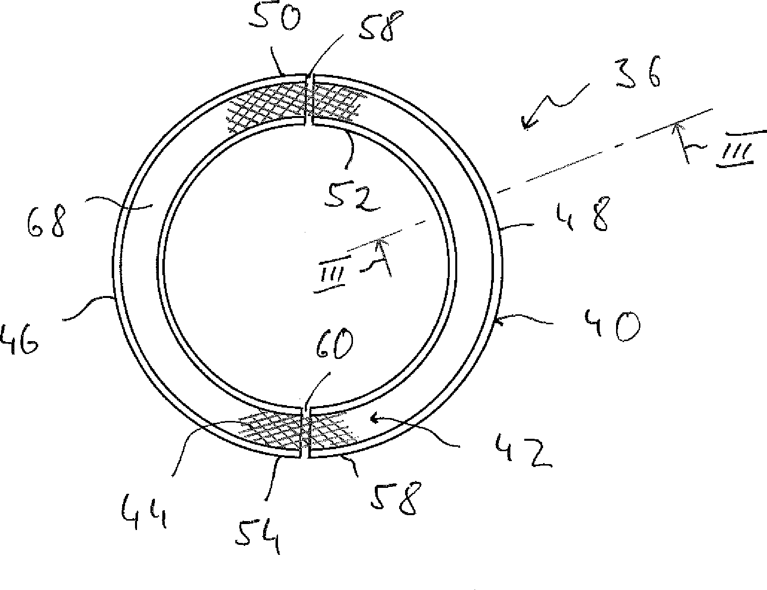
Ein Stützring (36) für ein Abgasführungssystem, insbesondere einer Brennkraftmaschine eines Fahrzeugs, umfasst einen Stützelementenkörper (40) mit einer Mehrzahl von Körpersegmenten (46, 48) und eine die Körpersegmente (46, 48) miteinander verbindende Stützanordnung (42). A support ring (36) for an exhaust delivery system, in particular an internal combustion engine of a vehicle, comprises a support element body (40) having a plurality of body segments (46, 48) and a support assembly (42) interconnecting the body segments (46, 48).
Description
Die vorliegende Erfindung betrifft einen Stützring, welcher beispielsweise in einem Abgasführungssystem einer Brennkraftmaschine eines Fahrzeugs eingesetzt werden kann, um eine Abstützwirkung für eine im Abgasführungssystem vorgesehene Abgasbehandlungsanordnung, beispielsweise Katalysatoranordnung, zu erzeugen. The present invention relates to a support ring, which can be used, for example, in an exhaust system of an internal combustion engine of a vehicle in order to produce a supporting effect for an exhaust gas treatment system provided in the exhaust treatment arrangement, such as catalyst arrangement.
In
In dem Abgasführungselement
In Zuordnung zu wenigstens einem der beiden in Richtung einer Längsachse A der Abgasführungsbaugruppe
Jeder Stützring
Aus der
Die
Es ist die Aufgabe der vorliegenden Erfindung, einen Stützring für ein Abgasführungssystem vorzusehen, welcher bei einfacher Herstellbarkeit eine zuverlässige Stützwirkung, beispielsweise für eine Abgasbehandlungsanordnung in einem Abgasführungssystem einer Brennkraftmaschine eines Fahrzeugs, erzeugen kann. It is the object of the present invention to provide a support ring for an exhaust system, which can produce a reliable support effect, for example, for an exhaust treatment system in an exhaust system of an internal combustion engine of a vehicle with ease of manufacture.
Erfindungsgemäß wird diese Aufgabe gelöst durch einen Stützring für ein Abgasführungssystem, insbesondere einer Brennkraftmaschine eines Fahrzeugs, umfassend einen Stützelementenkörper mit einer Mehrzahl von Körpersegmenten und eine die Körpersegmente miteinander verbindende Stützanordnung. According to the invention this object is achieved by a support ring for an exhaust system, in particular an internal combustion engine of a vehicle, comprising a support element body having a plurality of body segments and a body segments connecting the support assembly.
Da bei dem erfindungsgemäßen Stützring der Stützelementenkörper eine Mehrzahl von Körpersegmenten umfasst, also mit einer Mehrzahl von zusammen den Stützelementenkörper bereitstellenden Bauteilen aufgebaut ist, kann jedes dieser Körpersegmente in einfacher, gleichwohl jedoch präziser Art und Weise beispielsweise durch Umformen eines Blechrohlings generiert werden, so dass in seiner Gesamtheit der Stützelementenkörper beispielsweise mit kreisringartiger Struktur und einer Mehrzahl von in Umfangsrichtung aufeinander folgenden Körpersegmenten aufgebaut sein kann. Da keines der Körpersegmente sich über einen gesamten Umfangsbereich erstrecken muss, können diese auch bei der grundsätzlich gekrümmten Konfiguration mit hoher Fertigungspräzision bereitgestellt werden, so dass einerseits eine zuverlässige Stützwirkung nach radial außen erzeugt werden kann, um den Stützring in einem Abgasführungselement halten zu können, andererseits aber zuverlässig auch die Abstützwirkung für eine Abgasbehandlungsanordnung generiert werden kann. Since in the support ring according to the invention the support element body comprises a plurality of body segments, that is constructed with a plurality of together the support member body providing components, each of these body segments can be generated in a simple, yet precise manner, for example by reshaping a sheet metal blank, so that in its entirety of the support element body may be constructed, for example, with an annular structure and a plurality of circumferentially successive body segments. Since none of the body segments must extend over an entire peripheral area, they can be provided with high manufacturing precision even in the basically curved configuration, so that on the one hand a reliable support effect can be generated radially outward to hold the support ring in an exhaust guide element, on the other but reliably the support effect for an exhaust treatment arrangement can be generated.
Um den strukturellen Zusammenhalt des Stützrings in einfacher Weise bereitstellen zu können, wird vorgeschlagen, dass wenigstens zwei Körpersegmente in einander gegenüberliegenden Körpersegmentendbereichen aneinander angrenzen, und dass die Stützanordnung die Körpersegmente miteinander verbindet. Bei dem erfindungsgemäßen Stützring erfüllt die Stützanordnung also nicht nur die Funktionalität zum Abstützen beispielsweise einer Abgasbehandlungsanordnung, sondern sorgt auch dafür, dass die grundsätzlich voneinander getrennt aufgebauten Körpersegmente miteinander verbunden werden. In order to provide the structural integrity of the support ring in a simple manner For example, it is proposed that at least two body segments adjoin one another in opposing body segment end regions, and that the support assembly interconnects the body segments. In the support ring according to the invention, therefore, the support arrangement not only fulfills the functionality for supporting, for example, an exhaust gas treatment arrangement, but also ensures that the body segments, which are basically constructed separately from one another, are connected to one another.
Um das Auftreten von Zwängungen beim Eingliedern eines erfindungsgemäßen Stützrings in ein beispielsweise rohrartiges Abgasführungselement vermeiden zu können, wird vorgeschlagen, dass zwischen den Körpersegmentendbereichen ein Zwischenraum gebildet ist. In order to avoid the occurrence of constraints when incorporating a support ring according to the invention into a tube-like exhaust guide element, for example, it is proposed that a gap is formed between the Körpersegmentendbereichen.
Vorteilhafterweise ist wenigstens ein, vorzugsweise jedes Körpersegment mit einem U-Profil ausgebildet, wobei die Stützanordnung wenigstens teilweise in einem U-Profilinnenraum aufgenommen ist. Advantageously, at least one, preferably each body segment is formed with a U-profile, wherein the support assembly is at least partially received in a U-profile interior.
Um die Stützwechselwirkung des Stützelements beispielsweise mit einer Abgasbehandlungsanordnung bereitstellen zu können bzw. nicht zu beeinträchtigen, wird weiter vorgeschlagen, dass das U-Profil einen radial inneren U-Schenkel, einen radial äußeren U-Schenkel und einen die U-schenkel verbindenden Verbindungsbereich aufweist, und dass ein U-Schenkel, vorzugsweise der radial innere U-Schenkel, kürzer ist, als der andere U-Schenkel. Vorteilhafterweise erstreckt sich dabei dann die Stützanordnung in Richtung vom Verbindungsbereich weg wenigstens über den kürzeren U-Schenkel hinaus. In order to be able to provide or not to impair the support interaction of the support element, for example with an exhaust treatment arrangement, it is further proposed that the U-profile has a radially inner U-leg, a radially outer U-leg and a connection area connecting the U-thighs, and that one U-leg, preferably the radially inner U-leg, is shorter than the other U-leg. Advantageously, then extends the support assembly in the direction away from the connection area at least over the shorter U-leg out.
Zur Abstützwechselwirkung beispielsweise mit einer Abgasbehandlungsanordnung wird vorgeschlagen, dass die Stützanordnung flexibel ist. Vorteilhafterweise ist sie auch ringartig, vorzugsweise geschlossen ringartig ausgebildet, so dass über den gesamten Umfangsbereich einerseits die Stützwirkung erlangt werden kann, andererseits aber auch der Zusammenhalt der einzelnen Körpersegmente des Stützelementenkörpers erreicht wird. For support interaction, for example with an exhaust treatment arrangement, it is proposed that the support arrangement is flexible. Advantageously, it is also ring-like, preferably closed ring-like design, so that on the one hand, the support effect can be obtained over the entire peripheral region, but on the other hand, the cohesion of the individual body segments of the support body is achieved.
Um eine kostengünstige Herstellbarkeit zu gewährleisten, andererseits jedoch auch einen Aufbau zu erlangen, welcher für die vergleichsweise aggressive Umgebung in einem Abgasführungssystem geeignet ist, kann weiter vorgesehen sein, dass wenigstens ein Körpersegment, vorzugsweise jedes Körpersegment, als Blechumformteil ausgebildet ist. In order to ensure a cost-effective manufacturability, on the other hand, however, to obtain a structure which is suitable for the relatively aggressive environment in an exhaust system, it can further be provided that at least one body segment, preferably each body segment, is formed as a sheet metal forming part.
Um auch die Stützanordnung für die vergleichsweise aggressive Umgebung geeignet auszugestalten, wird vorgeschlagen, dass diese mit Drahtmaterial aufgebaut ist, vorzugsweise mit Drahtgestrick, Drahtgewirk, Drahtgeflecht oder Drahtgewebe, also allgemein einem Material, das z. B. aus einer Mehrzahl von Drahtfilamenten einen Volumenkörper bereitstellt. In order to design the support assembly for the relatively aggressive environment suitable, it is proposed that this is constructed with wire material, preferably with wire mesh, Drahtgewirk, wire mesh or wire mesh, so generally a material that z. B. provides a solid from a plurality of wire filaments.
Um einen stabilen Zusammenhalt zu gewährleisten, wird vorgeschlagen, dass wenigstens ein Körpersegment, vorzugsweise jedes Körpersegment, mit der Stützanordnung fest verbunden ist, vorzugsweise durch Reibschluss oder/und Materialschluss. In order to ensure a stable cohesion, it is proposed that at least one body segment, preferably each body segment, is fixedly connected to the support assembly, preferably by frictional engagement and / or material closure.
Die vorliegende Erfindung betrifft ferner eine Abgasführungsbaugruppe für ein Abgasführungssystem, insbesondere für eine Brennkraftmaschine eines Fahrzeugs, umfassend ein rohrartiges Abgasführungselement, eine in dem Abgasführungselement angeordnete Abgasbehandlungsanordnung, vorzugsweise Katalysatoranordnung, sowie an wenigstens einem Endbereich der Abgasbehandlungsanordnung einen Stützring mit dem vorangehend beschriebenen Aufbau. The present invention further relates to an exhaust-gas guide assembly for an exhaust-gas guidance system, in particular for an internal combustion engine of a vehicle, comprising a tubular exhaust-gas guide element, an exhaust-gas treatment element arranged in the exhaust-gas guide element, preferably a catalyst arrangement, and at at least one end region of the exhaust-gas treatment device a support ring with the construction described above.
Die vorliegende Erfindung wird nachfolgend mit Bezug auf die beiliegenden Figuren detailliert beschrieben. Es zeigt: The present invention will be described below in detail with reference to the accompanying drawings. It shows:
Eine Abgasführungsbaugruppe
In
Wie die
In einen jeweiligen U-Profilinnenraum
Um einen stabilen Verbund des Stützelements
Man erkennt in
Eine alternative Ausgestaltungsform des Stützrings
Mit der erfindungsgemäßen Ausgestaltung eines Stützrings wird es möglich, bei einfachem, gleichwohl jedoch präzise zu fertigendem Aufbau ein Mittel bereitzustellen, welches eine Abgasbehandlungsanordnung, beispielsweise eine Katalysatoranordnung, zuverlässig in einem rohrartigen Abgasführungselement eines Abgasführungssystems einer Brennkraftmaschine haltern kann und insbesondere auch im radial äußeren Randbereich eine Schutzwirkung gegen Korrosion bereitstellen kann. Durch die aufgrund des erfindungsgemäßen Aufbaus vorgesehene Flexibilität auch in Umfangs- und somit Radialrichtung wird weiterhin dafür gesorgt, dass das Stützelement selbst zuverlässig in einem rohrartigen Abgasführungselement gehaltert wird, ohne dass hierfür zusätzliche Befestigungsmaßnahmen erforderlich sind. With the embodiment of a support ring according to the invention, it is possible to provide a simple but nevertheless precise construction a means which can reliably support an exhaust treatment arrangement, for example a catalyst arrangement in a tubular exhaust guide element of an exhaust system of an internal combustion engine and in particular also in the radially outer edge region Can provide protection against corrosion. Due to the flexibility provided by the construction according to the invention also in the circumferential and thus radial direction is further ensured that the support element itself is reliably supported in a tubular exhaust guide element, without the need for additional attachment measures are required.
Claims (17)
Priority Applications (5)
| Application Number | Priority Date | Filing Date | Title |
|---|---|---|---|
| DE102015100552.2A DE102015100552B3 (en) | 2015-01-15 | 2015-01-15 | Support ring for an exhaust system |
| EP16150593.8A EP3045694B1 (en) | 2015-01-15 | 2016-01-08 | Support ring for exhaust gas conduit system |
| US14/994,553 US9765680B2 (en) | 2015-01-15 | 2016-01-13 | Support ring for an exhaust gas duct system |
| CN201610021501.7A CN105804839B (en) | 2015-01-15 | 2016-01-14 | Support ring for being vented guiding system and exhaustion guiding structure component |
| JP2016006154A JP2016133120A (en) | 2015-01-15 | 2016-01-15 | Support ring for exhaust gas guide system |
Applications Claiming Priority (1)
| Application Number | Priority Date | Filing Date | Title |
|---|---|---|---|
| DE102015100552.2A DE102015100552B3 (en) | 2015-01-15 | 2015-01-15 | Support ring for an exhaust system |
Publications (1)
| Publication Number | Publication Date |
|---|---|
| DE102015100552B3 true DE102015100552B3 (en) | 2016-06-16 |
Family
ID=55077438
Family Applications (1)
| Application Number | Title | Priority Date | Filing Date |
|---|---|---|---|
| DE102015100552.2A Active DE102015100552B3 (en) | 2015-01-15 | 2015-01-15 | Support ring for an exhaust system |
Country Status (5)
| Country | Link |
|---|---|
| US (1) | US9765680B2 (en) |
| EP (1) | EP3045694B1 (en) |
| JP (1) | JP2016133120A (en) |
| CN (1) | CN105804839B (en) |
| DE (1) | DE102015100552B3 (en) |
Cited By (1)
| Publication number | Priority date | Publication date | Assignee | Title |
|---|---|---|---|---|
| EP4047192A1 (en) * | 2021-02-18 | 2022-08-24 | Purem GmbH | Support assembly for supporting an exhaust gas treatment element received in a housing |
Families Citing this family (4)
| Publication number | Priority date | Publication date | Assignee | Title |
|---|---|---|---|---|
| DE102016121721A1 (en) | 2016-11-14 | 2018-05-17 | Eberspächer Exhaust Technology GmbH & Co. KG | Method for producing a flap carrier for an exhaust flap |
| CN108868970A (en) * | 2018-06-14 | 2018-11-23 | 山东沃蓝环保设备有限公司 | A kind of exhaust gas processing device using plug-in connection method |
| CN108533368A (en) * | 2018-06-14 | 2018-09-14 | 山东沃蓝环保设备有限公司 | A kind of exhaust gas cleaner of installation heating device |
| DE102019121411A1 (en) * | 2019-08-08 | 2021-02-11 | Eberspächer Exhaust Technology GmbH & Co. KG | Exhaust treatment assembly |
Citations (3)
| Publication number | Priority date | Publication date | Assignee | Title |
|---|---|---|---|---|
| DE10300780A1 (en) * | 2003-01-11 | 2004-07-22 | J. Eberspächer GmbH & Co. KG | Exhaust gas treatment device |
| DE102004051512A1 (en) * | 2004-10-21 | 2006-05-04 | J. Eberspächer GmbH & Co. KG | Particulate filter for an exhaust system |
| DE602005004455T2 (en) * | 2004-07-30 | 2009-01-15 | Delphi Technologies, Inc., Troy | Gas treatment device and method for its production and its use |
Family Cites Families (13)
| Publication number | Priority date | Publication date | Assignee | Title |
|---|---|---|---|---|
| JPS53148881A (en) * | 1977-05-31 | 1978-12-25 | Matsushita Electric Works Ltd | Shutter for illuminator |
| US4393559A (en) * | 1981-07-14 | 1983-07-19 | Heckethorn Manufacturing Company | U-Bolt clamp with tubular reinforcing means |
| US4643458A (en) * | 1984-04-06 | 1987-02-17 | Ammar Jesse I | Support and clamping assembly |
| JPS644096Y2 (en) * | 1985-10-31 | 1989-02-02 | ||
| JP2000018029A (en) * | 1998-06-30 | 2000-01-18 | Calsonic Corp | Manifold converter |
| US7501005B2 (en) * | 2005-02-28 | 2009-03-10 | Caterpillar Inc. | Exhaust treatment device having submerged connecting flanges |
| JP5173180B2 (en) * | 2006-10-30 | 2013-03-27 | 株式会社キャタラー | Exhaust gas purification catalyst |
| JP2009150242A (en) * | 2007-12-19 | 2009-07-09 | Nippon Reinz Co Ltd | Buffer member for ceramic honeycomb, and its manufacturing method |
| JP4834041B2 (en) * | 2008-08-04 | 2011-12-07 | 本田技研工業株式会社 | Exhaust gas purification device |
| JP2010190124A (en) * | 2009-02-18 | 2010-09-02 | Toyota Industries Corp | Exhaust emission control device |
| DE102009014435A1 (en) * | 2009-03-26 | 2010-10-14 | J. Eberspächer GmbH & Co. KG | Exhaust gas treatment device |
| US8136770B2 (en) * | 2009-08-24 | 2012-03-20 | International Engine Intellectual Property Company, Llc | Mount for exhaust system components |
| WO2011066041A1 (en) * | 2009-11-30 | 2011-06-03 | Acs Industries, Inc. | Mounting assemblies for substrates |
-
2015
- 2015-01-15 DE DE102015100552.2A patent/DE102015100552B3/en active Active
-
2016
- 2016-01-08 EP EP16150593.8A patent/EP3045694B1/en active Active
- 2016-01-13 US US14/994,553 patent/US9765680B2/en not_active Expired - Fee Related
- 2016-01-14 CN CN201610021501.7A patent/CN105804839B/en active Active
- 2016-01-15 JP JP2016006154A patent/JP2016133120A/en active Pending
Patent Citations (3)
| Publication number | Priority date | Publication date | Assignee | Title |
|---|---|---|---|---|
| DE10300780A1 (en) * | 2003-01-11 | 2004-07-22 | J. Eberspächer GmbH & Co. KG | Exhaust gas treatment device |
| DE602005004455T2 (en) * | 2004-07-30 | 2009-01-15 | Delphi Technologies, Inc., Troy | Gas treatment device and method for its production and its use |
| DE102004051512A1 (en) * | 2004-10-21 | 2006-05-04 | J. Eberspächer GmbH & Co. KG | Particulate filter for an exhaust system |
Cited By (2)
| Publication number | Priority date | Publication date | Assignee | Title |
|---|---|---|---|---|
| EP4047192A1 (en) * | 2021-02-18 | 2022-08-24 | Purem GmbH | Support assembly for supporting an exhaust gas treatment element received in a housing |
| US11781460B2 (en) | 2021-02-18 | 2023-10-10 | Purem GmbH | Support assembly |
Also Published As
| Publication number | Publication date |
|---|---|
| CN105804839B (en) | 2018-11-06 |
| EP3045694A1 (en) | 2016-07-20 |
| US9765680B2 (en) | 2017-09-19 |
| CN105804839A (en) | 2016-07-27 |
| US20160208673A1 (en) | 2016-07-21 |
| EP3045694B1 (en) | 2017-12-20 |
| JP2016133120A (en) | 2016-07-25 |
Similar Documents
| Publication | Publication Date | Title |
|---|---|---|
| DE102015100552B3 (en) | Support ring for an exhaust system | |
| DE112008004188T5 (en) | Grommet | |
| EP2831441B1 (en) | Slave cylinder | |
| EP1887194A1 (en) | Exhaust gas purification device | |
| DE202007013516U1 (en) | damping arrangement | |
| DE102014012169A1 (en) | decoupling element | |
| DE102010022708A1 (en) | Valve drive for internal combustion engine, has camshaft where cam carrier is arranged in rotationally fixed and axially displaceable manner | |
| DE102013106075A1 (en) | Device for the vibration-decoupled connection of two devices of an exhaust system | |
| EP2913495B1 (en) | Method for manufacturing an exhaust gas treatment device and corresponding exhaust gas treatment device | |
| EP3199772A1 (en) | Sound generator for an exhaust system | |
| DE20023409U1 (en) | Element for neutralizing vibrations in exhaust pipe system of internal combustion engine has annular bead formed on upstream guide component in region of end connected to bellows | |
| EP2479400A1 (en) | Flexible conduit section for a waste gas conduit of a combustion engine | |
| EP1241389B1 (en) | Pipe member having a metal bellow | |
| DE102015220528A1 (en) | Welding structure for a warm-up catalyst | |
| DE102012216097B4 (en) | decoupling element | |
| DE102022111864A1 (en) | Heating device | |
| EP3401584B1 (en) | Pipe, in particular exhaust pipe | |
| DE102014100296A1 (en) | Flexible conduit element with insulation | |
| EP3093057B1 (en) | Filter for insertion into a fluid-bearing pipe | |
| EP1873368B1 (en) | Flexible metal tube with sealing ring | |
| DE202022107189U1 (en) | Flexible line element | |
| DE102017101107A1 (en) | Damper for a hydraulic clutch | |
| EP4047192A1 (en) | Support assembly for supporting an exhaust gas treatment element received in a housing | |
| DE102011086840A1 (en) | Flexible line unit, particularly for exhaust system of internal combustion engine of vehicle, has helically corrugated or ring-shaped corrugated metal bellows and metal knitted fabric hose or netting hose | |
| DE202007006720U1 (en) | Decoupling element with extension |
Legal Events
| Date | Code | Title | Description |
|---|---|---|---|
| R012 | Request for examination validly filed | ||
| R016 | Response to examination communication | ||
| R018 | Grant decision by examination section/examining division | ||
| R020 | Patent grant now final | ||
| R081 | Change of applicant/patentee |
Owner name: PUREM GMBH, DE Free format text: FORMER OWNER: EBERSPAECHER EXHAUST TECHNOLOGY GMBH & CO. KG, 66539 NEUNKIRCHEN, DE |
|
| R082 | Change of representative |
Representative=s name: RUTTENSPERGER LACHNIT TROSSIN GOMOLL, PATENT- , DE |