EP2233702A2 - Lageranordnung - Google Patents
Lageranordnung Download PDFInfo
- Publication number
- EP2233702A2 EP2233702A2 EP10153717A EP10153717A EP2233702A2 EP 2233702 A2 EP2233702 A2 EP 2233702A2 EP 10153717 A EP10153717 A EP 10153717A EP 10153717 A EP10153717 A EP 10153717A EP 2233702 A2 EP2233702 A2 EP 2233702A2
- Authority
- EP
- European Patent Office
- Prior art keywords
- bearing
- shaft
- arrangement according
- bearing arrangement
- race
- Prior art date
- Legal status (The legal status is an assumption and is not a legal conclusion. Google has not performed a legal analysis and makes no representation as to the accuracy of the status listed.)
- Withdrawn
Links
- 230000015572 biosynthetic process Effects 0.000 claims description 8
- 230000001141 propulsive effect Effects 0.000 claims description 3
- 238000006073 displacement reaction Methods 0.000 claims 1
- 238000005452 bending Methods 0.000 description 10
- 238000002485 combustion reaction Methods 0.000 description 5
- 239000003921 oil Substances 0.000 description 4
- 230000001419 dependent effect Effects 0.000 description 2
- 239000000446 fuel Substances 0.000 description 2
- 230000003068 static effect Effects 0.000 description 2
- 229910052581 Si3N4 Inorganic materials 0.000 description 1
- 230000002411 adverse Effects 0.000 description 1
- 230000008878 coupling Effects 0.000 description 1
- 238000010168 coupling process Methods 0.000 description 1
- 238000005859 coupling reaction Methods 0.000 description 1
- 230000003467 diminishing effect Effects 0.000 description 1
- 230000009977 dual effect Effects 0.000 description 1
- 230000003993 interaction Effects 0.000 description 1
- 239000003562 lightweight material Substances 0.000 description 1
- 239000000463 material Substances 0.000 description 1
- 239000000203 mixture Substances 0.000 description 1
- 239000010705 motor oil Substances 0.000 description 1
- 238000005086 pumping Methods 0.000 description 1
- 238000005096 rolling process Methods 0.000 description 1
- HQVNEWCFYHHQES-UHFFFAOYSA-N silicon nitride Chemical compound N12[Si]34N5[Si]62N3[Si]51N64 HQVNEWCFYHHQES-UHFFFAOYSA-N 0.000 description 1
Images
Classifications
-
- F—MECHANICAL ENGINEERING; LIGHTING; HEATING; WEAPONS; BLASTING
- F01—MACHINES OR ENGINES IN GENERAL; ENGINE PLANTS IN GENERAL; STEAM ENGINES
- F01D—NON-POSITIVE DISPLACEMENT MACHINES OR ENGINES, e.g. STEAM TURBINES
- F01D25/00—Component parts, details, or accessories, not provided for in, or of interest apart from, other groups
- F01D25/16—Arrangement of bearings; Supporting or mounting bearings in casings
-
- F—MECHANICAL ENGINEERING; LIGHTING; HEATING; WEAPONS; BLASTING
- F16—ENGINEERING ELEMENTS AND UNITS; GENERAL MEASURES FOR PRODUCING AND MAINTAINING EFFECTIVE FUNCTIONING OF MACHINES OR INSTALLATIONS; THERMAL INSULATION IN GENERAL
- F16C—SHAFTS; FLEXIBLE SHAFTS; ELEMENTS OR CRANKSHAFT MECHANISMS; ROTARY BODIES OTHER THAN GEARING ELEMENTS; BEARINGS
- F16C19/00—Bearings with rolling contact, for exclusively rotary movement
- F16C19/50—Other types of ball or roller bearings
- F16C19/505—Other types of ball or roller bearings with the diameter of the rolling elements of one row differing from the diameter of those of another row
-
- F—MECHANICAL ENGINEERING; LIGHTING; HEATING; WEAPONS; BLASTING
- F16—ENGINEERING ELEMENTS AND UNITS; GENERAL MEASURES FOR PRODUCING AND MAINTAINING EFFECTIVE FUNCTIONING OF MACHINES OR INSTALLATIONS; THERMAL INSULATION IN GENERAL
- F16C—SHAFTS; FLEXIBLE SHAFTS; ELEMENTS OR CRANKSHAFT MECHANISMS; ROTARY BODIES OTHER THAN GEARING ELEMENTS; BEARINGS
- F16C19/00—Bearings with rolling contact, for exclusively rotary movement
- F16C19/54—Systems consisting of a plurality of bearings with rolling friction
- F16C19/55—Systems consisting of a plurality of bearings with rolling friction with intermediate floating or independently-driven rings rotating at reduced speed or with other differential ball or roller bearings
-
- F—MECHANICAL ENGINEERING; LIGHTING; HEATING; WEAPONS; BLASTING
- F16—ENGINEERING ELEMENTS AND UNITS; GENERAL MEASURES FOR PRODUCING AND MAINTAINING EFFECTIVE FUNCTIONING OF MACHINES OR INSTALLATIONS; THERMAL INSULATION IN GENERAL
- F16C—SHAFTS; FLEXIBLE SHAFTS; ELEMENTS OR CRANKSHAFT MECHANISMS; ROTARY BODIES OTHER THAN GEARING ELEMENTS; BEARINGS
- F16C23/00—Bearings for exclusively rotary movement adjustable for aligning or positioning
- F16C23/06—Ball or roller bearings
- F16C23/08—Ball or roller bearings self-adjusting
-
- F—MECHANICAL ENGINEERING; LIGHTING; HEATING; WEAPONS; BLASTING
- F16—ENGINEERING ELEMENTS AND UNITS; GENERAL MEASURES FOR PRODUCING AND MAINTAINING EFFECTIVE FUNCTIONING OF MACHINES OR INSTALLATIONS; THERMAL INSULATION IN GENERAL
- F16C—SHAFTS; FLEXIBLE SHAFTS; ELEMENTS OR CRANKSHAFT MECHANISMS; ROTARY BODIES OTHER THAN GEARING ELEMENTS; BEARINGS
- F16C27/00—Elastic or yielding bearings or bearing supports, for exclusively rotary movement
- F16C27/04—Ball or roller bearings, e.g. with resilient rolling bodies
-
- F—MECHANICAL ENGINEERING; LIGHTING; HEATING; WEAPONS; BLASTING
- F05—INDEXING SCHEMES RELATING TO ENGINES OR PUMPS IN VARIOUS SUBCLASSES OF CLASSES F01-F04
- F05D—INDEXING SCHEME FOR ASPECTS RELATING TO NON-POSITIVE-DISPLACEMENT MACHINES OR ENGINES, GAS-TURBINES OR JET-PROPULSION PLANTS
- F05D2240/00—Components
- F05D2240/50—Bearings
- F05D2240/52—Axial thrust bearings
-
- F—MECHANICAL ENGINEERING; LIGHTING; HEATING; WEAPONS; BLASTING
- F16—ENGINEERING ELEMENTS AND UNITS; GENERAL MEASURES FOR PRODUCING AND MAINTAINING EFFECTIVE FUNCTIONING OF MACHINES OR INSTALLATIONS; THERMAL INSULATION IN GENERAL
- F16C—SHAFTS; FLEXIBLE SHAFTS; ELEMENTS OR CRANKSHAFT MECHANISMS; ROTARY BODIES OTHER THAN GEARING ELEMENTS; BEARINGS
- F16C19/00—Bearings with rolling contact, for exclusively rotary movement
- F16C19/02—Bearings with rolling contact, for exclusively rotary movement with bearing balls essentially of the same size in one or more circular rows
- F16C19/14—Bearings with rolling contact, for exclusively rotary movement with bearing balls essentially of the same size in one or more circular rows for both radial and axial load
- F16C19/18—Bearings with rolling contact, for exclusively rotary movement with bearing balls essentially of the same size in one or more circular rows for both radial and axial load with two or more rows of balls
-
- F—MECHANICAL ENGINEERING; LIGHTING; HEATING; WEAPONS; BLASTING
- F16—ENGINEERING ELEMENTS AND UNITS; GENERAL MEASURES FOR PRODUCING AND MAINTAINING EFFECTIVE FUNCTIONING OF MACHINES OR INSTALLATIONS; THERMAL INSULATION IN GENERAL
- F16C—SHAFTS; FLEXIBLE SHAFTS; ELEMENTS OR CRANKSHAFT MECHANISMS; ROTARY BODIES OTHER THAN GEARING ELEMENTS; BEARINGS
- F16C2360/00—Engines or pumps
- F16C2360/23—Gas turbine engines
Definitions
- the present invention relates to a bearing arrangement and more particularly, although not exclusively, to a thrust bearing.
- Thrust bearings represent a subset of rotary bearings which are designed to support a rotating member under axial loading. Examples in which such axial loading can occur include shafts in, for example, gas turbine engines, wind turbines or other load-bearing shafts in marine, aerospace or automotive drive systems. The following description proceeds in relation to thrust bearings for gas turbine engines but may be equally applicable to other thrust bearing applications.
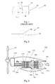
- FIG 1 there is shown an exemplary thrust bearing arrangement in which an engine powerplant 10 drives a gearbox 12 via a rotating shaft 14.
- the powerplant and gearbox are both mounted to a supporting structure, shown generally at 16.
- Bearing arrangements 18 and 20 are mounted in a spaced relationship on the shaft 14 in the vicinity of the power plant 10 and the gearbox 12 respectively.
- the supporting structure may comprise one or a number of connecting members defining a force path between the powerplant 10 and gearbox 12 and hence the associated bearings 18 and 20.
- Single row (thrust) ball bearings are widely used in many applications where there is the requirement to accommodate both axial and radial loads under high or low speeds.
- the bearing stiffness can be considered a constant for the system and so, if a shaft reduces in diameter and/or if the distance between the bearings is increased, the stiffness of the shaft reduces and the relative impact of the stiffness of the bearing 20 on the system is increased. In an arrangement which has a relatively long, thin and/or flexible shaft, the majority of the stiffness of the system derives from the bearing stiffness.
- the ability for conventional single row ball bearings to withstand misalignment is limited. Misalignment will result in higher ball loads within the bearing and a reduction in bearing life.
- the degree of misalignment considered to be allowable for a particular system depends on a number of factors, including the internal geometry of the bearing design; the physical size of the bearing; the magnitude of applied forces in a radial direction; the duration of the twist on the shaft; and, the stiffness of the shaft and housing. The interaction of these factors will define the maximum angular misalignment possible for the given bearing arrangement.
- a bearing arrangement for supporting a shaft relative to a support structure, the shaft being rotatable about an axis of rotation
- the bearing arrangement comprising a first bearing having radially inner and outer races, the inner race being rotatable relative to the outer race in use, and a second bearing arranged such that the first bearing is mounted to the support structure via the second bearing so as to allow compliance of the first bearing in use in a radial direction relative to the axis of rotation.
- the second bearing may be mounted to, or assembled with, said first bearing.
- the bearing arrangement and/or first bearing may comprise a thrust bearing.
- the bearing arrangement may comprise an engine shaft bearing arrangement.
- the shaft may be arranged to drive a fan or propeller.
- the first bearing accommodates the rotation of the shaft about a shaft axis and the second bearing accommodates, at least in part, angular deflection of the shaft along its axis.
- the second bearing comprises inner and outer bearing races.
- the outer race of the first bearing comprises the inner race of the second bearing.
- the outer race of the first bearing may have inner and outer surfaces, the inner surface of which is shaped to accommodate the bearing members of the first bearing and the outer surface of which is shaped to accommodate bearing members of the second bearing.
- the first and second bearings may comprise respective radially inner and outer bearings relative to the shaft axis.
- the second bearing may be axially offset from the first bearing relative to the shaft axis.
- first and/or second bearings may comprise ball bearing members mounted between opposing races thereof.
- the first bearing may alternatively comprise a roller bearing or hydrodynamic bearing or a plain bearing, which may or may not comprise a bushing.
- Inner and outer races of the second bearing may be mounted to the support structure in such a manner as to prevent relative rotation between the inner and outer races and the support structure.
- the second bearing may be fixed against rotation about the axis of rotation of the shaft.
- the second bearing may allow deflection of the first bearing in a direction substantially parallel and/or perpendicular to the shaft axis.
- the outer race of the second bearing may be welded to the support structure or else a member interposed between said outer race and the support structure.
- a connector may connect the outer race of the first bearing to the support structure so as to prevent relative rotation therebetween.
- the second bearing may be arranged to be mounted to the support structure via a fixing formation.
- the fixing formation may comprise a base and a seal member arranged to define in part a bearing chamber.
- the inner and outer races of the second bearing are shaped to define an opening for reception of a ball bearing, opposing portions of the opening being defined by each of the inner and outer races.
- the inner and outer races may be arranged to be angularly offset about the shaft axis such that the opposing portions of the opening are spaced in use.
- a bearing arrangement race member for use in the first aspect, the race member having first and second surfaces, the first surface arranged to accommodate bearing members of the first bearing and the second surface arranged to accommodate bearing members of the second bearing.
- the race member may comprise a single or multi-part body, which may be generally annular in shape.
- the first and second surfaces may be opposing inner and outer surfaces of the annular body.
- a bearing arrangement for supporting a rotatable shaft relative to a support structure, the bearing arrangement comprising a first bearing having radially inner and outer races, the inner race being rotatable relative to the outer race in use, and a hinge structure arranged such that the first bearing is mountable to the support structure via the hinge structure.
- the hinge structure may comprise the second bearing according to the first aspect. Any features of the first and second aspects may be applied to the third aspect comprising a hinge structure.
- the bearing arrangement of any aspect may be arranged for use in high speed applications, such as for example within a gas turbine engine.
- the support structure may comprise a housing structure for the engine.
- 'bearing' as used herein is intended to be interpreted in its broadest sense as a device to allow relative motion between two parts in a constrained manner.
- a gas turbine engine is generally indicated at 100 of the type conventionally referred to as a turboprop.
- the gas turbine engine 100 has a principal and rotational axis 101.
- the engine 100 comprises, in flow series, a propeller 102, an engine air intake 104, a compressor 106, combustion equipment 108, a high-pressure turbine 110, a low-pressure turbine 112, and a core engine exhaust 114.
- a casing 113 and nacelles 115 generally surround the core engine and defines the shape of intake 104. It will be appreciated by those skilled in the art that the various possible mounting arrangements for turboprop engines on aircraft result in various possible forms of nacelle and intake profiles.
- the gas turbine engine 100 works in a conventional manner so that air entering the intake 104 is compressed by the rotating blades of compressor 106 prior to entering the combustion equipment 108.
- the axial compressor 106 comprises a plurality of discs mounted to a drum, each disc having blades mounted thereon in a conventional manner.
- Each compressor disk may have associated therewith a circumferential set of fixed stators or vanes depending inwardly from the casing 113 so as to provide a plurality of compressor stages.
- the compressed air enters the combustion equipment where it is mixed with fuel emanating from fuel injectors 109 and the mixture combusted. Upon exit from the combustion equipment, the resultant hot combustion products expand and thereby drive the high and low-pressure turbines 110 and 112 before being exhausted through the exhaust 114 in the direction of arrow A.
- the high pressure turbine 110 is connected to and thereby drives the high pressure compressor 106 by interconnecting shaft 116.
- the low pressure turbine 112 is connected to, and thereby drives, the propeller 102 via shaft 118.
- a gearing arrangement 119 is connected in the force path between the shaft 118 and the propeller 102 in order to drive the propeller at a suitable rotational speed to provide propulsive thrust for an aircraft.
- the core engine exhaust 114 comprises a nozzle formation to provide additional propulsive thrust.
- turboprop engine can in many ways be likened to that of a two-shaft turbofan engine save that the propeller 102 is generally larger than the fan of a turbofan engine and is not ducted.
- present invention may be applied to other forms of gas turbine engine, such as turbofans, or other applications in which a rotating shaft is to be supported by a bearing.
- the present invention provides for a compliant bearing arrangement in which a primary bearing is supported by a secondary bearing.
- the primary bearing may comprise a ball bearing, a roller bearing, a hydrodynamic bearing or a plain bearing, which may or may not comprise a bushing.
- Ball and roller bearing systems both comprise a plurality of bearing members or elements which are individually rotatable about axes which are spaced form the main axis of rotation of the system (e.g. the main shaft axis). These types of bearing are collectively referred to as roller element bearings.
- the bearing arrangement of the present invention is used to support shaft 118, typically referred to as the mainline shaft.
- shaft rotates at high speed, typically operating at thousands of revolutions per minute and thus a high speed bearing system is required.
- the range of rotational speeds may vary significantly dependent on size and application and may be as low as 1,000-2,000 rpm for propeller applications up to as great as 100,000-200,000 rpm for smaller micro-turbines.
- the present invention may be applicable to the entirety of this range or only a portion thereof, which is considered to encompass high speed applications and associated high speed bearings.
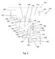
- FIG 4 An embodiment of the present invention is shown in figure 4 .
- the sectional view is of the lower half of bearing arrangement 120 and is taken through a plane containing the shaft axis 101.
- the bearing arrangement 120 supports the shaft 118 relative to a fixed structure, which in this embodiment is a component of housing structure 126.
- the bearing arrangement in general comprises radially inner 122 and outer 124 bearings arranged such that the inner bearing 122 is interposed between the outer bearing 124 and the shaft 118. Alternatively stated, the inner bearing is supported by the fixed structure 126 via the outer bearing 124.
- the inner 122 and outer 124 bearings are hereinafter referred to as respective primary and secondary bearings.
- the shaft 118 in this embodiment is hollow having a shaft bore 128.
- the outer wall of the shaft 118 is shaped to receive the inner race 130 of primary bearing 122.
- the shaft wall is shaped so as to provide an abutment formation 132 in the form of an annular wall against which the inner race 130 is located.
- the inner bearing race 130 is held in place on the shaft 118 by a retaining member in the form of a ring nut 134 which locks the inner bearing race against the abutment formation 132.
- the inner bearing race 130 is shaped to receive a plurality of ball bearing members 136 in a conventional manner.
- the inner bearing race has a circumferential groove or other shaped formation for receiving the ball bearings 136 so as to allow movement of the ball bearings 136 about the inner race 132 during operation.
- the outer race 138 opposes the inner race and is also shaped to receive the ball bearings therein such that the balls bearings 136 are trapped between the inner and outer races in a conventional manner.
- the ball bearings are held in a cage 140 which serves to preserve the relative spacing between the ball bearings whilst allowing rotation thereof about the inner bearing race 130 at high speeds.
- a cage 140 which serves to preserve the relative spacing between the ball bearings whilst allowing rotation thereof about the inner bearing race 130 at high speeds.
- Any conventional form of cage may be used as will be understood by a person skilled in the art.
- the outer race 138 is rigidly connected to the housing for example by way of a bolted flange joint.
- the present invention allows for a more compliant arrangement in which the primary bearing 122 is connected to the housing by a secondary bearing 124. Such an arrangement reduces the stiffness of the bearing system and thus provides for a system which is more tolerant to misalignment which may occur due to bending loads applied to the shaft during use.
- the compliant nature of the bearing arrangement of the present invention means that the angular stiffness of the bearing is reduced and thus the load applied through the bearing arrangement upon bending of the shaft is also reduced.
- the reduction of the stiffness of the bearing system results in a diminishing effect of the 'step' 26 in figure 2 , such that the stiffness of the shaft is the predominant stiffness of the overall shaft-and-bearing system. Under such circumstances, the load carried by the ball bearings is reduced such that the life and reliability of the bearing arrangement can be improved.
- the primary bearing outer race 138 in the embodiment of figure 4 has an outward facing surface 142 which is shaped to accommodate secondary bearing members 144.
- the outward facing surface comprises a circumferential grove 146 which partially surrounds the ball bearings 144 of the secondary bearing 124.
- the outer race 148 of the secondary bearing is provided with a curved inner facing surface 150 which opposes the outward facing surface of the race 138 so as to define a partially enclosed channel or raceway there-between in which the ball bearings 144 are seated.
- the races of the secondary bearing do not undergo relative rotation during operation as both races 138 and 148 are fixed relative to the housing 126.
- the bearing race 148 is welded to fixing 152 at 154. Whilst the alternative of a ring of bolts is possible it is considered in many ways preferable to fix the outer race 148 using an annular weld.
- the secondary bearing is assembled directly to the bearing housing support structure.
- the ball members 144 may be formed from a lightweight material such as silicon nitride or other suitable material.
- the centre 156 of the balls 144 in the secondary bearing (i.e. the centre of the secondary bearing) is axially offset from the centre 158 of the balls 136 of the primary bearing (i.e. the centre of the primary bearing).
- the relative location of the secondary bearing 124 allows the primary main-line bearing 122 to pivot or rotate about the secondary bearing in response to bending or misalignment of the shaft 118.
- the bearing arrangement 120 also allows for a greater degree of angular deflection of the shaft. In essence, both the primary and secondary bearings share any shaft misalignment.
- the secondary bearing is manufactured to allow for small radial clearances but a large axial clearance.
- misalignment may need to be accounted for, such as a static or stationary misalignment or else a dynamic misalignment which may rotate with the shaft or which may be dynamically independent.
- the present invention may accommodate any or all such types of misalignment.
- the secondary bearing 124 is assembled by inserting the ball bearing members 144 into the bearing channel between members 138 and 148 via an assembly slot 160.
- a bearing slot is formed in the members 138 and/or 148 to allow an opening which is large enough to allow the balls 144 to pass there-through one at a time.
- An angular restraint may be provided in order to ensure that the slot portions do not become realigned during use.
- Any suitable form of conventional fixing may be used for this purpose which may comprise a releasable fixing.
- a secondary bearing of this type provides for simplicity of assembly, which may take place as part of an engine or module assembly or else which may be assembled separately or 'on the bench'.
- the overall bearing arrangement may be considered a biaxial bearing assembly.
- a seal 162 is provided adjacent the primary bearing 122 and is mounted on seal arm 164, which provides an air seal for the bearing chamber there-behind.
- the bearing chamber provides a air-and-oil environment through which oil is fed to the bearing arrangement and subsequently scavenged by the main engine oil scavenge system.
- oil scavenge holes (not shown) in the outer race 148 of the secondary bearing to allow oil to pass there-through.
- the seal arm 164 has a base or footing which takes the from of the fixing 152. In this manner the bearing arrangement is mounted to the seal arm fixing 152 at 154, which is in turn mounted to the housing structure 126 by bolts 166 which pass through a mounting flange formation 168 depending from fixing 152.
- a connector member 170 is attached between the fixing 152 and the primary bearing 122.
- the connector is mounted between a projection 172 on the primary bearing outer race 138 and a projection 174 on the fixing 152.
- the connector 170 serves to prevent rotation of the member 138 in use and, as such, acts as a 'dog' or 'tang' arrangement which is secured to the fixing 152 using a simple fastener, such as spring clip 176.
- the shaft 118 rotates about axis 101 along with the inner race 130 of primary bearing 122.
- the ball bearings 136 roll around the inner bearing race 130, whilst outer bearing race 138 is held stationary relative to the housing structure 126 by connector 170.
- the member 138 performs a dual function and serves as both the primary bearing outer race and also the secondary bearing inner race.
- the secondary bearing 124 remains stationary relating to the housing structure 126 and allows for slight angular deflection of the primary bearing relative to the axis 101 in response to angular deflection of the shaft 118.
Landscapes
- Engineering & Computer Science (AREA)
- General Engineering & Computer Science (AREA)
- Mechanical Engineering (AREA)
- Rolling Contact Bearings (AREA)
Applications Claiming Priority (1)
| Application Number | Priority Date | Filing Date | Title |
|---|---|---|---|
| GBGB0905110.3A GB0905110D0 (en) | 2009-03-25 | 2009-03-25 | Bearing arrangement |
Publications (1)
| Publication Number | Publication Date |
|---|---|
| EP2233702A2 true EP2233702A2 (de) | 2010-09-29 |
Family
ID=40640127
Family Applications (1)
| Application Number | Title | Priority Date | Filing Date |
|---|---|---|---|
| EP10153717A Withdrawn EP2233702A2 (de) | 2009-03-25 | 2010-02-16 | Lageranordnung |
Country Status (3)
| Country | Link |
|---|---|
| US (1) | US8292509B2 (de) |
| EP (1) | EP2233702A2 (de) |
| GB (1) | GB0905110D0 (de) |
Cited By (1)
| Publication number | Priority date | Publication date | Assignee | Title |
|---|---|---|---|---|
| EP2942538B1 (de) * | 2014-04-17 | 2022-06-01 | Raytheon Technologies Corporation | Mehrfachlager-stapelrückhaltung |
Families Citing this family (9)
| Publication number | Priority date | Publication date | Assignee | Title |
|---|---|---|---|---|
| US8900083B2 (en) | 2011-04-27 | 2014-12-02 | United Technologies Corporation | Fan drive gear system integrated carrier and torque frame |
| US8777793B2 (en) | 2011-04-27 | 2014-07-15 | United Technologies Corporation | Fan drive planetary gear system integrated carrier and torque frame |
| US8727935B2 (en) | 2012-07-30 | 2014-05-20 | United Technologies Corporation | Fan drive gear system torque frame pin retainer |
| US20140219598A1 (en) * | 2012-10-02 | 2014-08-07 | Andrew P. Grosskopf | Variable frequency generator input shaft bearing |
| EP2829756B1 (de) * | 2013-07-26 | 2016-06-29 | SKF Magnetic Mechatronics S.A.S. | Hilfskugellager für ein magnetisch aufgehängtes Rotorsystem |
| US9359073B2 (en) | 2013-08-02 | 2016-06-07 | Sikorsky Aircraft Corporation | Aircraft tail rotor system |
| US9382940B2 (en) * | 2014-05-12 | 2016-07-05 | Schaeffler Technologies AG & Co. KG | Triple race angular contact bearing |
| EP3431388B1 (de) * | 2017-07-17 | 2024-08-28 | Ratier-Figeac SAS | Propellerschaufeln |
| US11750089B2 (en) | 2021-10-28 | 2023-09-05 | Alpha And Omega Semiconductor International Lp | Power converter for high power density |
Family Cites Families (21)
| Publication number | Priority date | Publication date | Assignee | Title |
|---|---|---|---|---|
| US1433014A (en) * | 1921-01-26 | 1922-10-24 | Samuel S Stewart | Compound ball bearing |
| US1506856A (en) * | 1923-02-20 | 1924-09-02 | Thomas J Mccluskey | Bearing |
| US2518159A (en) * | 1945-05-11 | 1950-08-08 | Gen Electric | Bearing support for dynamoelectric machines |
| US2822225A (en) * | 1955-05-18 | 1958-02-04 | F I Saemann | Ball bearing assembly |
| GB961522A (en) * | 1963-01-09 | 1964-06-24 | Rolls Royce | Bearing assembly |
| GB1008886A (en) * | 1964-06-12 | 1965-11-03 | Rolls Royce | Gas turbine engine |
| DE1425006A1 (de) * | 1963-12-13 | 1969-01-02 | Eisenwerk Rote Erde Gmbh | Waelzlager-Drehverbindung |
| US3737202A (en) * | 1971-07-19 | 1973-06-05 | Ackley D | Redundant bearing |
| JPS62159791A (ja) | 1986-01-08 | 1987-07-15 | Hitachi Ltd | 高速回転機械の制振機構 |
| US4664539A (en) * | 1986-02-13 | 1987-05-12 | Florida State University | Serial safety bearing |
| JPH0280809A (ja) | 1988-09-19 | 1990-03-20 | Hitachi Ltd | 軸受装置と、この軸受装置を用いた磁気デイスク装置 |
| DE9410511U1 (de) * | 1994-06-29 | 1994-08-11 | Skf Gmbh | Dreiringlager |
| DE9412908U1 (de) | 1994-08-10 | 1995-12-07 | Sirona Dental Systems GmbH, 64625 Bensheim | Zahnärztliche Antriebseinheit mit einer in Wälzlagern gelagerten Welle |
| US6478469B1 (en) * | 2000-11-03 | 2002-11-12 | Accessible Technologies, Inc. | Velocity variance reducing multiple bearing arrangement for impeller shaft of centrifugal supercharger |
| DE10208692A1 (de) | 2001-08-28 | 2003-03-20 | Kaltenbach & Voigt | Medizinisches oder dentalmedizinisches Handstück mit einem in einem Wälzlager gelagerten Drehteil |
| GB0309830D0 (en) | 2003-04-29 | 2003-06-04 | Boc Group Plc | A vacuum pump |
| DE102005007776A1 (de) * | 2005-02-19 | 2006-08-31 | Mtu Aero Engines Gmbh | Lageranordnung |
| GB0509190D0 (en) | 2005-05-05 | 2005-06-15 | Boc Group Plc | Vacuum pump |
| GB2432649A (en) * | 2005-11-23 | 2007-05-30 | Autoliv Dev | A steering wheel arrangement with an integrally formed ball bearing race |
| EP1990192A2 (de) | 2007-04-28 | 2008-11-12 | Koenig & Bauer Aktiengesellschaft | Lagerungen eines Zylinders einer Rotationsdruckmaschine |
| US8292508B2 (en) * | 2009-01-15 | 2012-10-23 | Nsk Corporation | Integrated two-level bearing |
-
2009
- 2009-03-25 GB GBGB0905110.3A patent/GB0905110D0/en not_active Ceased
-
2010
- 2010-02-16 EP EP10153717A patent/EP2233702A2/de not_active Withdrawn
- 2010-02-16 US US12/706,554 patent/US8292509B2/en not_active Expired - Fee Related
Non-Patent Citations (1)
| Title |
|---|
| None |
Cited By (1)
| Publication number | Priority date | Publication date | Assignee | Title |
|---|---|---|---|---|
| EP2942538B1 (de) * | 2014-04-17 | 2022-06-01 | Raytheon Technologies Corporation | Mehrfachlager-stapelrückhaltung |
Also Published As
| Publication number | Publication date |
|---|---|
| US8292509B2 (en) | 2012-10-23 |
| US20100247015A1 (en) | 2010-09-30 |
| GB0905110D0 (en) | 2009-05-06 |
Similar Documents
| Publication | Publication Date | Title |
|---|---|---|
| US8292509B2 (en) | Bearing arrangement | |
| CN104011336B (zh) | 用于燃气涡轮发动机的轴承支承装置 | |
| US8727629B2 (en) | Series bearing support apparatus for a gas turbine engine | |
| EP3040567B1 (de) | Lageranordnung mit zwei wälzlagern und druckkammern zum vorspannen der wälzlager und zum gleichmässigen verteilen der axiallast auf beide lager | |
| US7269938B2 (en) | Counter-rotating gas turbine engine and method of assembling same | |
| US9238973B2 (en) | Gas turbine engine and foil bearing system | |
| US6540483B2 (en) | Methods and apparatus for bearing outer race axial retention | |
| CN114555927B (zh) | 包括滚子轴承和斜接触的双列滚珠轴承的涡轮机风扇组件 | |
| EP2994666A1 (de) | Lüfterantriebgetriebesystem mit verbesserter fehlausrichtungsfähigkeit | |
| EP3040568A1 (de) | Lageranordnung mit zwei nebeneinander angeordneten wälzlagern und einer druckkammer mit federnder wand zum vorspannen der wälzlager und zum gleichmässigen verteilen der axiallast auf beide lager | |
| US8065867B2 (en) | Radial ball bearing | |
| EP3715655B1 (de) | Lageranordnung | |
| EP3835606B1 (de) | Feder zur zentrierung eines gekrümmten trägers für ein drucklager | |
| CN114962002B (zh) | 带有弹性支撑的轴承组件及航空发动机 | |
| US20180156114A1 (en) | Bearing for turbine engines | |
| US12497908B2 (en) | Turbine engine including a fan assembly having a damper | |
| EP3734094A1 (de) | Wellenfängersystem | |
| Sato et al. | Design, Analysis, and Tests of Differential Planetary Gear System for Open Rotor Power Gearbox |
Legal Events
| Date | Code | Title | Description |
|---|---|---|---|
| PUAI | Public reference made under article 153(3) epc to a published international application that has entered the european phase |
Free format text: ORIGINAL CODE: 0009012 |
|
| AK | Designated contracting states |
Kind code of ref document: A2 Designated state(s): AT BE BG CH CY CZ DE DK EE ES FI FR GB GR HR HU IE IS IT LI LT LU LV MC MK MT NL NO PL PT RO SE SI SK SM TR |
|
| AX | Request for extension of the european patent |
Extension state: AL BA RS |
|
| RAP1 | Party data changed (applicant data changed or rights of an application transferred) |
Owner name: ROLLS-ROYCE PLC |
|
| STAA | Information on the status of an ep patent application or granted ep patent |
Free format text: STATUS: THE APPLICATION HAS BEEN WITHDRAWN |
|
| 18W | Application withdrawn |
Effective date: 20161201 |