EP2233684A2 - Magnetische Gleithalterung für ein Bohrlochwerkzeug - Google Patents
Magnetische Gleithalterung für ein Bohrlochwerkzeug Download PDFInfo
- Publication number
- EP2233684A2 EP2233684A2 EP10154559A EP10154559A EP2233684A2 EP 2233684 A2 EP2233684 A2 EP 2233684A2 EP 10154559 A EP10154559 A EP 10154559A EP 10154559 A EP10154559 A EP 10154559A EP 2233684 A2 EP2233684 A2 EP 2233684A2
- Authority
- EP
- European Patent Office
- Prior art keywords
- mandrel
- tool
- slip
- magnetic component
- magnetic
- Prior art date
- Legal status (The legal status is an assumption and is not a legal conclusion. Google has not performed a legal analysis and makes no representation as to the accuracy of the status listed.)
- Granted
Links
- 230000005291 magnetic effect Effects 0.000 title claims abstract description 67
- 230000014759 maintenance of location Effects 0.000 title abstract description 5
- 239000003302 ferromagnetic material Substances 0.000 claims description 12
- 230000004913 activation Effects 0.000 claims description 7
- 239000000696 magnetic material Substances 0.000 description 6
- 238000004519 manufacturing process Methods 0.000 description 4
- 230000005294 ferromagnetic effect Effects 0.000 description 3
- 239000000463 material Substances 0.000 description 3
- 229910052761 rare earth metal Inorganic materials 0.000 description 3
- 150000002910 rare earth metals Chemical class 0.000 description 3
- 239000012530 fluid Substances 0.000 description 2
- 238000000034 method Methods 0.000 description 2
- 230000000717 retained effect Effects 0.000 description 2
- 229910000831 Steel Inorganic materials 0.000 description 1
- 230000003213 activating effect Effects 0.000 description 1
- 230000004075 alteration Effects 0.000 description 1
- 239000002131 composite material Substances 0.000 description 1
- 230000007423 decrease Effects 0.000 description 1
- 230000009977 dual effect Effects 0.000 description 1
- 238000002347 injection Methods 0.000 description 1
- 239000007924 injection Substances 0.000 description 1
- 238000012986 modification Methods 0.000 description 1
- 230000004048 modification Effects 0.000 description 1
- 238000012856 packing Methods 0.000 description 1
- 239000010959 steel Substances 0.000 description 1
Images


Classifications
-
- E—FIXED CONSTRUCTIONS
- E21—EARTH OR ROCK DRILLING; MINING
- E21B—EARTH OR ROCK DRILLING; OBTAINING OIL, GAS, WATER, SOLUBLE OR MELTABLE MATERIALS OR A SLURRY OF MINERALS FROM WELLS
- E21B33/00—Sealing or packing boreholes or wells
- E21B33/10—Sealing or packing boreholes or wells in the borehole
- E21B33/12—Packers; Plugs
- E21B33/129—Packers; Plugs with mechanical slips for hooking into the casing
-
- E—FIXED CONSTRUCTIONS
- E21—EARTH OR ROCK DRILLING; MINING
- E21B—EARTH OR ROCK DRILLING; OBTAINING OIL, GAS, WATER, SOLUBLE OR MELTABLE MATERIALS OR A SLURRY OF MINERALS FROM WELLS
- E21B23/00—Apparatus for displacing, setting, locking, releasing or removing tools, packers or the like in boreholes or wells
- E21B23/06—Apparatus for displacing, setting, locking, releasing or removing tools, packers or the like in boreholes or wells for setting packers
Definitions
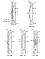
- a slip 20 is positioned on a tool housing or mandrel 10 between a movable wedge 12 and another (fixed or movable) wedge 14.
- the tool mandrel 10 When the tool mandrel 10 is set at depth, activation of the tool moves the wedges 12 and 14 closer together to push the slip away from the mandrel 10 so it can engage the inside of a surrounding tubular.
- a plurality of rings 30 fit through the slip 20 and around the mandrel 10. When the wedges 12/14 are separated as shown, the rings 30 hold the slip 20 next to the mandrel 10 so that the slip 20 does not extend beyond the tool's profile. When pushed out from the mandrel 10, however, the slip 20 overcomes the hold of the rings 30.
- a bow or leaf spring 32 can be positioned in Fig. 1 between the cage 16 and the slip 20 to bias the slip 20 against the mandrel 10.
- a shear pin may no longer be used to retain the slip once broken. Therefore, problems with debris and fluid passing around the unretained slip may occur as the tool is pulled out of the hole.
- FIG. 1 illustrates a slip held to a mandrel using rings according to the prior art.
- FIG. 2A illustrates a slip held to a mandrel using magnets on the mandrel.
- FIG. 2B illustrates a slip held to a mandrel using magnets on the slip.
- FIG. 2D illustrates a slip held to a mandrel using opposing magnets on the mandrel and the slip.
- FIG. 3 illustrates portion of a packer having slips held to the valve's mandrel using magnets on the slip.
- FIG. 4 illustrates portion of a compression-set retrievable service packer having slips held to the packer's mandrel using opposing magnets on the slip and mandrel.
- FIG. 5 illustrates portion of a retrievable bridge plug having slips held to the packer's mandrel using attracting magnets on the slip and mandrel.
- FIG. 6 illustrates portion of a retrievable casing packer having slips held to the packer's mandrel using separately located magnets on the slip and mandrel.
- FIGS. 8, 9, and 10 illustrate liner hangers having slips held using various arrangements of magnetic components.
- the force pulls the slip away from the magnetic component that retains the slip, allowing the slip to engage a surrounding tubular.
- the magnetic component can be inserted into the tool's mandrel, into the slip, or into both the mandrel and the slip.
- the magnetic component can also be affixed to the mandrel or to some other component that retains the slip. Using the magnetic component advantageously reduces the mechanical complexity required to retain the slip on a tool and eliminates the creation of debris.
- a slip 20 is positioned adjacent a tool mandrel 10 between activation bodies (e.g ., wedge members) 12 and 14.
- a center strip 16 of a cage that may be part of the tool's mandrel 10 may ultimately prevent the slip 20 from becoming loose from the mandrel 10.
- one or more magnetic components 40 on the mandrel 10 retain the slip 20 adjacent the mandrel 10 as long as a setting force is not applied by the wedge members 12 and 14.
- the slip 20 can be composed of a ferromagnetic material, such as steel or the like, allowing it to be attracted to the magnetic components 40 on the mandrel 10.
- the mandrel 10 can also be composed of a ferromagnetic material, but could be composed of something else, such as a composite or other non-ferromagnetic material.
- magnetic components 44 and 46 both on the slip 20 and portion 16 of the mandrel 10 retain the slip 20 against the mandrel 10.
- the facing magnetic components 44 and 46 are permanent magnets that oppose one another in a repulsive relation (e.g ., North-to-North or South-to-South polarity configuration).
- the magnetic repulsion forces the slip 20 against the mandrel 10 as long as the wedge members 12 and 14 remain separated.
- the magnetic component 46 on the mandrel 10 can be disposed on a cage portion 16 that limits the slip 20's movement, but the component 46 could be positioned elsewhere on the mandrel 10.
- FIG. 3 shows a portion of a packer 50 for passing in tubing and isolating the annulus.
- the packer 50 has a mandrel 52, a packing element 54, and slip cage 56 with slots 58.
- Slips 60 position in the cage's slots 58 and can be pushed outward from the mandrel 52 by wedge members 62 and 64.
- FIG. 4 shows a portion of a compression-set retrievable service packer 70 used to isolate a wellbore annulus from a production conduit.
- the packer 70 has a mandrel 72 with upper and lower mandrels 74 and 76. Slips 80 position between the mandrels 72 and 74 and are held partially in slots in the lower mandrel 76. Opposing permanent magnets 44 and 46 (one 44 on the slip 80 and another 46 on the lower mandrel 76) retain the slips 80 against the mandrel 72. When the space decreases between the upper and lower mandrels 72 and 74 during activation, a wedge portion 82 pushes the slips 80 out from the mandrel 72 against the opposing force of the permanent magnets 44 and 46.
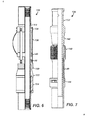
- FIG. 5 shows a portion of a retrievable bridge plug 90 used for plugging tubing downhole.
- the plug 90 has a mandrel 92 with upper and lower mandrels 94 and 96 positioned thereon.
- Slips 100 have one end fixed to pivot at the upper mandrel 94 and have another end to engage a surrounding tubular when jarring movements push the lower mandrel's wedge member 102 against the slips 100.
- springs 104 that mechanically retain the slips 100
- attractive magnetic components 40 and 42 respectively on the mandrel 92 and slips 100 retain the slips 100 adjacent the mandrel 92 as long as the tool is not set.
- Both components 40 and 42 can be permanent magnets to attract one another.
- one can be a permanent magnet, while the other can be a ferromagnetic element.
- FIG. 7 shows a portion of a tubing stop 130 for setting in tubing and holding force from above from a gas lift bumper spring or the like.
- the stop 130 has slips 140 pivotably anchored at one end 144 and engagable by a wedge portion 142 of the mandrel 132 to be pushed outward toward a surrounding tubular.
- One or more large magnetic elements 40 in form of a sleeve on the stop's mandrel 132 retain the slips 140 to the mandrel 132 while not engaged by the wedge portion 142.
- the elements 40 can have other suitable shapes.
- FIGS. 8, 9, and 10 show liner hangers 140, 160, and 180 having slips held using various arrangements of magnetic components.
- the liner hanger 140 has a mandrel 142 and a wedge member 152.
- Slips 150 have wickers 156 with ends 154 attached adjacent the mandrel 142.
- the slip 150s' second ends are movable by the wedge member 152 to engage a surrounding tubular.
- First and second magnetic components 40 and 42 on the mandrel 142 and slips 150 retain the slips' ends adjacent the mandrel 142 while the hanger 140 is run in and out of the hole. Once the wedge member 152 activates the slips 150, the magnetic retention is broken so the slips 150 can engage the surrounding tubular.
- the magnetic components 40 on the mandrel 142 can include a plurality of discrete permanent magnets disposed on the mandrel. Alternatively as shown, the magnetic component 40 can actually be a ring of permanent magnet material disposed around the outside of the mandrel 142.
- the liner hanger 160 has a mandrel 162 and dual wedges 172/173 for activating slips 170. As shown, one end 174 of the slip 170 is pivotably connected to a cage 164 on the mandrel 162, and the slip 170 is held within slots in the cage 164. As long as the wedges 172/173 remain in the position shown in FIG. 9 , the slips 170 are held adjacent to the mandrel 162.
- the wedges 172/173 are composed either entirely or partially of permanent magnetic material, and the slips 170 are either composed entirely or partially of ferromagnetic material, permanent magnetic material, or a combination thereof to be attracted to the wedges 172/173.
- the reverse arrangement is possible where the slips 170 are composed either entirely or partially of a permanent magnetic material and the wedges 172/173 are either composed entirely or partially ferromagnetic material, permanent magnetic material, or a combination thereof to be attracted to the slips 170.
- the liner hanger 180 has a mandrel 172, wedge member 192, and slip ring 194.
- the ring 194 has slip ends 190 that extend along slip springs 196 from the ring 194.
- Magnetic components 40/42 on the slip ends 190 and the adjacent portion of the mandrel 182 retain the slip ends 190 in place until activated by the wedge member 192.
- one or more magnetic components can be used.
- the magnetic components can be a ferromagnetic element or a permanent magnet, such as a rare earth magnet.
- the slips, wedges, or mandrel can be composed of a permanent magnetic material. It is possible that downhole debris may be attracted to any permanent magnets used on the downhole tool. The extent of this issue depends on the size and strength of any permanent magnets used for a given implementation. However, the magnets are preferably not outwardly exposed on the downhole tool to avoid or minimize the collection of debris. For example, permanent magnets used for the arrangement of magnetic components 40/42 in FIG.
- the magnetic components are shown in the drawings as being exposed on the surfaces of the slip, mandrel, wedges, etc., it may be preferred to embed the magnetic components inside these elements. This may be useful depending on the magnetic material used and its ability to withstand direct contact with the downhole environment. Embedding the magnetic component may also be useful when the exposed portion of the slip, mandrel, wedge, etc. encounters friction or the like.
- the magnetic components 40/42 on the liner hanger of FIG. 10 may be exposed to friction when the slips 190 ride on the wedge 192 to extend outward from the mandrel 182.
- it may be preferred that the magnetic component 42 on the slip 190 not be outwardly exposed and caused to ride directly on the wedge 192.
Landscapes
- Life Sciences & Earth Sciences (AREA)
- Engineering & Computer Science (AREA)
- Geology (AREA)
- Mining & Mineral Resources (AREA)
- Physics & Mathematics (AREA)
- Environmental & Geological Engineering (AREA)
- Fluid Mechanics (AREA)
- General Life Sciences & Earth Sciences (AREA)
- Geochemistry & Mineralogy (AREA)
- Earth Drilling (AREA)
Applications Claiming Priority (1)
| Application Number | Priority Date | Filing Date | Title |
|---|---|---|---|
| US12/409,661 US8069918B2 (en) | 2009-03-24 | 2009-03-24 | Magnetic slip retention for downhole tool |
Publications (3)
| Publication Number | Publication Date |
|---|---|
| EP2233684A2 true EP2233684A2 (de) | 2010-09-29 |
| EP2233684A3 EP2233684A3 (de) | 2013-07-10 |
| EP2233684B1 EP2233684B1 (de) | 2020-11-25 |
Family
ID=42358335
Family Applications (1)
| Application Number | Title | Priority Date | Filing Date |
|---|---|---|---|
| EP10154559.8A Not-in-force EP2233684B1 (de) | 2009-03-24 | 2010-02-24 | Magnetische Gleithalterung für ein Bohrlochwerkzeug |
Country Status (3)
| Country | Link |
|---|---|
| US (2) | US8069918B2 (de) |
| EP (1) | EP2233684B1 (de) |
| CA (1) | CA2696645C (de) |
Cited By (2)
| Publication number | Priority date | Publication date | Assignee | Title |
|---|---|---|---|---|
| US9440341B2 (en) | 2013-09-18 | 2016-09-13 | Vetco Gray Inc. | Magnetic frame and guide for anti-rotation key installation |
| WO2022146675A1 (en) * | 2020-12-29 | 2022-07-07 | Baker Hughes Oilfield Operations Llc | Inflow test packer tool and method |
Families Citing this family (12)
| Publication number | Priority date | Publication date | Assignee | Title |
|---|---|---|---|---|
| US8464786B2 (en) * | 2010-07-20 | 2013-06-18 | Schlumberger Technology Corporation | Non basepipe-welded accessory attachment |
| AR079760A1 (es) * | 2010-12-28 | 2012-02-15 | Texproil S R L | Dispositivo de empaquetamiento hidraulico recuperable utilizable en pozos de agua, gas y petroleo o fluidos similares |
| US20140034332A1 (en) * | 2012-08-02 | 2014-02-06 | Jerry Allamon | Workstring Disconnect Tool and Method of Use |
| JP5482975B1 (ja) * | 2012-08-24 | 2014-05-07 | 新日鐵住金株式会社 | 内面規制工具、プラグ、芯金、熱間圧延機、プレス穿孔機及び抽伸機 |
| US9677356B2 (en) | 2012-10-01 | 2017-06-13 | Weatherford Technology Holdings, Llc | Insert units for non-metallic slips oriented normal to cone face |
| WO2014126549A2 (en) * | 2013-02-12 | 2014-08-21 | Halliburton Energy Services, Inc. | Conveying data from a wellbore to a terranean surface |
| WO2016093865A1 (en) * | 2014-12-12 | 2016-06-16 | Halliburton Energy Services, Inc. | Slip segment inserts for a downhole tool |
| US9850725B2 (en) * | 2015-04-15 | 2017-12-26 | Baker Hughes, A Ge Company, Llc | One trip interventionless liner hanger and packer setting apparatus and method |
| GB2554614B (en) | 2015-08-27 | 2021-03-31 | Halliburton Energy Services Inc | Resettable pre-set mechanism for downhole tools |
| GB2555043B (en) | 2015-08-27 | 2021-04-07 | Halliburton Energy Services Inc | Bidirectional slips |
| CN106522868B (zh) * | 2017-01-12 | 2019-10-25 | 太仓优尼泰克精密机械有限公司 | 一种用于尾管悬挂器的助力胀封系统 |
| US10954745B2 (en) | 2019-07-03 | 2021-03-23 | Cnpc Usa Corporation | Plug assembly |
Family Cites Families (16)
| Publication number | Priority date | Publication date | Assignee | Title |
|---|---|---|---|---|
| US3006416A (en) * | 1961-10-31 | Stop device for well pipes | ||
| US2131274A (en) * | 1936-07-24 | 1938-09-27 | Merla Tool Company | Packer |
| US4058166A (en) * | 1976-03-29 | 1977-11-15 | Otis Engineering Corporation | Well setting tool |
| US4614233A (en) | 1984-10-11 | 1986-09-30 | Milton Menard | Mechanically actuated downhole locking sub |
| US5095979A (en) | 1990-07-12 | 1992-03-17 | Petro-Tech Tools Incorporated | Apparatus for operating a downhole tool using coil tubing |
| US5273109A (en) | 1991-01-11 | 1993-12-28 | Napoleon Arizmendi | Retrievable packer |
| US5540279A (en) | 1995-05-16 | 1996-07-30 | Halliburton Company | Downhole tool apparatus with non-metallic packer element retaining shoes |
| EP0828921B1 (de) * | 1995-05-31 | 2001-08-01 | Weatherford/Lamb Inc. | Mittel zur aktivierung eines werkzeugs im bohrloch |
| US5839515A (en) | 1997-07-07 | 1998-11-24 | Halliburton Energy Services, Inc. | Slip retaining system for downhole tools |
| US5984007A (en) | 1998-01-09 | 1999-11-16 | Halliburton Energy Services, Inc. | Chip resistant buttons for downhole tools having slip elements |
| US6119774A (en) | 1998-07-21 | 2000-09-19 | Baker Hughes Incorporated | Caged slip system |
| GB9912666D0 (en) * | 1999-05-29 | 1999-07-28 | Specialised Petroleum Serv Ltd | Magnetic well cleaning apparatus |
| US6568470B2 (en) | 2001-07-27 | 2003-05-27 | Baker Hughes Incorporated | Downhole actuation system utilizing electroactive fluids |
| US6988556B2 (en) * | 2002-02-19 | 2006-01-24 | Halliburton Energy Services, Inc. | Deep set safety valve |
| WO2006010124A2 (en) * | 2004-07-09 | 2006-01-26 | Flo-Rite Fluids, Inc. | Fluid conditioning system and method |
| GB0513645D0 (en) * | 2005-07-02 | 2005-08-10 | Specialised Petroleum Serv Ltd | Wellbore cleaning method and apparatus |
-
2009
- 2009-03-24 US US12/409,661 patent/US8069918B2/en not_active Expired - Fee Related
-
2010
- 2010-02-24 EP EP10154559.8A patent/EP2233684B1/de not_active Not-in-force
- 2010-03-09 CA CA2696645A patent/CA2696645C/en not_active Expired - Fee Related
-
2011
- 2011-10-31 US US13/285,440 patent/US20120043070A1/en not_active Abandoned
Non-Patent Citations (1)
| Title |
|---|
| None |
Cited By (2)
| Publication number | Priority date | Publication date | Assignee | Title |
|---|---|---|---|---|
| US9440341B2 (en) | 2013-09-18 | 2016-09-13 | Vetco Gray Inc. | Magnetic frame and guide for anti-rotation key installation |
| WO2022146675A1 (en) * | 2020-12-29 | 2022-07-07 | Baker Hughes Oilfield Operations Llc | Inflow test packer tool and method |
Also Published As
| Publication number | Publication date |
|---|---|
| CA2696645A1 (en) | 2010-09-24 |
| US8069918B2 (en) | 2011-12-06 |
| EP2233684B1 (de) | 2020-11-25 |
| US20120043070A1 (en) | 2012-02-23 |
| US20100243232A1 (en) | 2010-09-30 |
| EP2233684A3 (de) | 2013-07-10 |
| CA2696645C (en) | 2014-05-06 |
Similar Documents
| Publication | Publication Date | Title |
|---|---|---|
| US8069918B2 (en) | Magnetic slip retention for downhole tool | |
| US9719327B2 (en) | Magnetic key for operating a multi-position downhole tool | |
| US8678098B2 (en) | Magnetically coupled actuation apparatus and method | |
| AU2012229332B2 (en) | Remote subterranean tool activation system | |
| US20100175888A1 (en) | Downhole Device Actuator and Method | |
| EP2805006B1 (de) | Bohrlochaktivierungssystem unter verwendung von magneten und verfahren dafür | |
| US20190040699A1 (en) | Anti-preset mechanism for setting piston in downhole tools | |
| EP2660421A2 (de) | Aktorschalter für ein Bohrlochwerkzeug, Werkzeug und Verfahren | |
| EP3656972A1 (de) | Rückholbare wiederverbindungsvorrichtung mit innendichtung und keilen zum anschluss an der oberseite eines bestehenden rohrs in einem bohrloch | |
| AU2013406185B2 (en) | External slip having expandable slots and a retainer | |
| US10316600B2 (en) | Tubing hanger apparatus, system and methods | |
| CA2948467C (en) | Drag block assembly | |
| AU2016424204A1 (en) | High expansion metal back-up ring for packers and bridge plugs | |
| US20150047824A1 (en) | Multi-stage Locking System for Selective Release of a Potential Energy Force to Set a Subterranean Tool | |
| AU2016204767A1 (en) | Flexible emergency hanger and method of installation |
Legal Events
| Date | Code | Title | Description |
|---|---|---|---|
| PUAI | Public reference made under article 153(3) epc to a published international application that has entered the european phase |
Free format text: ORIGINAL CODE: 0009012 |
|
| 17P | Request for examination filed |
Effective date: 20100321 |
|
| AK | Designated contracting states |
Kind code of ref document: A2 Designated state(s): AT BE BG CH CY CZ DE DK EE ES FI FR GB GR HR HU IE IS IT LI LT LU LV MC MK MT NL NO PL PT RO SE SI SK SM TR |
|
| PUAL | Search report despatched |
Free format text: ORIGINAL CODE: 0009013 |
|
| AK | Designated contracting states |
Kind code of ref document: A3 Designated state(s): AT BE BG CH CY CZ DE DK EE ES FI FR GB GR HR HU IE IS IT LI LT LU LV MC MK MT NL NO PL PT RO SE SI SK SM TR |
|
| RIC1 | Information provided on ipc code assigned before grant |
Ipc: E21B 33/129 20060101AFI20130531BHEP Ipc: E21B 23/06 20060101ALI20130531BHEP |
|
| RBV | Designated contracting states (corrected) |
Designated state(s): AT BE BG CH CY CZ DE DK EE ES FI FR GB GR HR HU IE IS IT LI LT LU LV MC MK MT NL NO PL PT RO SE SI SK SM TR |
|
| RAP1 | Party data changed (applicant data changed or rights of an application transferred) |
Owner name: WEATHERFORD TECHNOLOGY HOLDINGS, LLC |
|
| STAA | Information on the status of an ep patent application or granted ep patent |
Free format text: STATUS: EXAMINATION IS IN PROGRESS |
|
| 17Q | First examination report despatched |
Effective date: 20170221 |
|
| 111Z | Information provided on other rights and legal means of execution |
Free format text: AT BE BG CH CY CZ DE DK EE ES FI FR GB GR HR HU IE IS IT LT LU LV MC MK MT NL NO PL PT RO SE SI SK SM TR AT BE BG CH CY CZ DE DK EE ES FI FR GB GR HR HU IE IS IT LT LU LV MC MK MT NL NO PL PT RO SE SI SK SM TR Effective date: 20200511 |
|
| GRAP | Despatch of communication of intention to grant a patent |
Free format text: ORIGINAL CODE: EPIDOSNIGR1 |
|
| STAA | Information on the status of an ep patent application or granted ep patent |
Free format text: STATUS: GRANT OF PATENT IS INTENDED |
|
| INTG | Intention to grant announced |
Effective date: 20200706 |
|
| GRAS | Grant fee paid |
Free format text: ORIGINAL CODE: EPIDOSNIGR3 |
|
| GRAA | (expected) grant |
Free format text: ORIGINAL CODE: 0009210 |
|
| STAA | Information on the status of an ep patent application or granted ep patent |
Free format text: STATUS: THE PATENT HAS BEEN GRANTED |
|
| AK | Designated contracting states |
Kind code of ref document: B1 Designated state(s): AT BE BG CH CY CZ DE DK EE ES FI FR GB GR HR HU IE IS IT LI LT LU LV MC MK MT NL NO PL PT RO SE SI SK SM TR |
|
| REG | Reference to a national code |
Ref country code: GB Ref legal event code: FG4D |
|
| REG | Reference to a national code |
Ref country code: CH Ref legal event code: EP |
|
| R11X | Information provided on other rights and legal means of execution (corrected) |
Free format text: AT BE BG CH CY CZ DE DK EE ES FI FR GB GR HR HU IE IS IT LT LU LV MC MK MT NL NO PL PT RO SE SI SK SM TR Effective date: 20200511 |
|
| REG | Reference to a national code |
Ref country code: DE Ref legal event code: R096 Ref document number: 602010065983 Country of ref document: DE |
|
| REG | Reference to a national code |
Ref country code: AT Ref legal event code: REF Ref document number: 1338510 Country of ref document: AT Kind code of ref document: T Effective date: 20201215 |
|
| REG | Reference to a national code |
Ref country code: IE Ref legal event code: FG4D |
|
| 111Z | Information provided on other rights and legal means of execution |
Free format text: AT BE BG CH CY CZ DE DK EE ES FI FR GB GR HR HU IE IS IT LT LU LV MC MK MT NL NO PL PT RO SE SI SK SM TR AT BE BG CH CY CZ DE DK EE ES FI FR GB GR HR HU IE IS IT LT LU LV MC MK MT NL NO PL PT RO SE SI SK SM TR Effective date: 20200511 |
|
| REG | Reference to a national code |
Ref country code: AT Ref legal event code: MK05 Ref document number: 1338510 Country of ref document: AT Kind code of ref document: T Effective date: 20201125 |
|
| REG | Reference to a national code |
Ref country code: NL Ref legal event code: MP Effective date: 20201125 |
|
| PG25 | Lapsed in a contracting state [announced via postgrant information from national office to epo] |
Ref country code: GR Free format text: LAPSE BECAUSE OF FAILURE TO SUBMIT A TRANSLATION OF THE DESCRIPTION OR TO PAY THE FEE WITHIN THE PRESCRIBED TIME-LIMIT Effective date: 20210226 Ref country code: FI Free format text: LAPSE BECAUSE OF FAILURE TO SUBMIT A TRANSLATION OF THE DESCRIPTION OR TO PAY THE FEE WITHIN THE PRESCRIBED TIME-LIMIT Effective date: 20201125 Ref country code: NO Free format text: LAPSE BECAUSE OF FAILURE TO SUBMIT A TRANSLATION OF THE DESCRIPTION OR TO PAY THE FEE WITHIN THE PRESCRIBED TIME-LIMIT Effective date: 20210225 Ref country code: PT Free format text: LAPSE BECAUSE OF FAILURE TO SUBMIT A TRANSLATION OF THE DESCRIPTION OR TO PAY THE FEE WITHIN THE PRESCRIBED TIME-LIMIT Effective date: 20210325 |
|
| PG25 | Lapsed in a contracting state [announced via postgrant information from national office to epo] |
Ref country code: LV Free format text: LAPSE BECAUSE OF FAILURE TO SUBMIT A TRANSLATION OF THE DESCRIPTION OR TO PAY THE FEE WITHIN THE PRESCRIBED TIME-LIMIT Effective date: 20201125 Ref country code: PL Free format text: LAPSE BECAUSE OF FAILURE TO SUBMIT A TRANSLATION OF THE DESCRIPTION OR TO PAY THE FEE WITHIN THE PRESCRIBED TIME-LIMIT Effective date: 20201125 Ref country code: SE Free format text: LAPSE BECAUSE OF FAILURE TO SUBMIT A TRANSLATION OF THE DESCRIPTION OR TO PAY THE FEE WITHIN THE PRESCRIBED TIME-LIMIT Effective date: 20201125 Ref country code: AT Free format text: LAPSE BECAUSE OF FAILURE TO SUBMIT A TRANSLATION OF THE DESCRIPTION OR TO PAY THE FEE WITHIN THE PRESCRIBED TIME-LIMIT Effective date: 20201125 Ref country code: BG Free format text: LAPSE BECAUSE OF FAILURE TO SUBMIT A TRANSLATION OF THE DESCRIPTION OR TO PAY THE FEE WITHIN THE PRESCRIBED TIME-LIMIT Effective date: 20210225 Ref country code: IS Free format text: LAPSE BECAUSE OF FAILURE TO SUBMIT A TRANSLATION OF THE DESCRIPTION OR TO PAY THE FEE WITHIN THE PRESCRIBED TIME-LIMIT Effective date: 20210325 |
|
| REG | Reference to a national code |
Ref country code: LT Ref legal event code: MG9D |
|
| PG25 | Lapsed in a contracting state [announced via postgrant information from national office to epo] |
Ref country code: HR Free format text: LAPSE BECAUSE OF FAILURE TO SUBMIT A TRANSLATION OF THE DESCRIPTION OR TO PAY THE FEE WITHIN THE PRESCRIBED TIME-LIMIT Effective date: 20201125 |
|
| PG25 | Lapsed in a contracting state [announced via postgrant information from national office to epo] |
Ref country code: LT Free format text: LAPSE BECAUSE OF FAILURE TO SUBMIT A TRANSLATION OF THE DESCRIPTION OR TO PAY THE FEE WITHIN THE PRESCRIBED TIME-LIMIT Effective date: 20201125 Ref country code: SM Free format text: LAPSE BECAUSE OF FAILURE TO SUBMIT A TRANSLATION OF THE DESCRIPTION OR TO PAY THE FEE WITHIN THE PRESCRIBED TIME-LIMIT Effective date: 20201125 Ref country code: SK Free format text: LAPSE BECAUSE OF FAILURE TO SUBMIT A TRANSLATION OF THE DESCRIPTION OR TO PAY THE FEE WITHIN THE PRESCRIBED TIME-LIMIT Effective date: 20201125 Ref country code: RO Free format text: LAPSE BECAUSE OF FAILURE TO SUBMIT A TRANSLATION OF THE DESCRIPTION OR TO PAY THE FEE WITHIN THE PRESCRIBED TIME-LIMIT Effective date: 20201125 Ref country code: EE Free format text: LAPSE BECAUSE OF FAILURE TO SUBMIT A TRANSLATION OF THE DESCRIPTION OR TO PAY THE FEE WITHIN THE PRESCRIBED TIME-LIMIT Effective date: 20201125 Ref country code: CZ Free format text: LAPSE BECAUSE OF FAILURE TO SUBMIT A TRANSLATION OF THE DESCRIPTION OR TO PAY THE FEE WITHIN THE PRESCRIBED TIME-LIMIT Effective date: 20201125 |
|
| REG | Reference to a national code |
Ref country code: DE Ref legal event code: R097 Ref document number: 602010065983 Country of ref document: DE |
|
| PG25 | Lapsed in a contracting state [announced via postgrant information from national office to epo] |
Ref country code: DK Free format text: LAPSE BECAUSE OF FAILURE TO SUBMIT A TRANSLATION OF THE DESCRIPTION OR TO PAY THE FEE WITHIN THE PRESCRIBED TIME-LIMIT Effective date: 20201125 |
|
| REG | Reference to a national code |
Ref country code: DE Ref legal event code: R119 Ref document number: 602010065983 Country of ref document: DE |
|
| PG25 | Lapsed in a contracting state [announced via postgrant information from national office to epo] |
Ref country code: MC Free format text: LAPSE BECAUSE OF FAILURE TO SUBMIT A TRANSLATION OF THE DESCRIPTION OR TO PAY THE FEE WITHIN THE PRESCRIBED TIME-LIMIT Effective date: 20201125 |
|
| PLBE | No opposition filed within time limit |
Free format text: ORIGINAL CODE: 0009261 |
|
| STAA | Information on the status of an ep patent application or granted ep patent |
Free format text: STATUS: NO OPPOSITION FILED WITHIN TIME LIMIT |
|
| GBPC | Gb: european patent ceased through non-payment of renewal fee |
Effective date: 20210225 |
|
| REG | Reference to a national code |
Ref country code: BE Ref legal event code: MM Effective date: 20210228 |
|
| PG25 | Lapsed in a contracting state [announced via postgrant information from national office to epo] |
Ref country code: IT Free format text: LAPSE BECAUSE OF FAILURE TO SUBMIT A TRANSLATION OF THE DESCRIPTION OR TO PAY THE FEE WITHIN THE PRESCRIBED TIME-LIMIT Effective date: 20201125 Ref country code: CH Free format text: LAPSE BECAUSE OF NON-PAYMENT OF DUE FEES Effective date: 20210228 Ref country code: LI Free format text: LAPSE BECAUSE OF NON-PAYMENT OF DUE FEES Effective date: 20210228 Ref country code: LU Free format text: LAPSE BECAUSE OF NON-PAYMENT OF DUE FEES Effective date: 20210224 Ref country code: NL Free format text: LAPSE BECAUSE OF FAILURE TO SUBMIT A TRANSLATION OF THE DESCRIPTION OR TO PAY THE FEE WITHIN THE PRESCRIBED TIME-LIMIT Effective date: 20201125 |
|
| 26N | No opposition filed |
Effective date: 20210826 |
|
| PG25 | Lapsed in a contracting state [announced via postgrant information from national office to epo] |
Ref country code: ES Free format text: LAPSE BECAUSE OF FAILURE TO SUBMIT A TRANSLATION OF THE DESCRIPTION OR TO PAY THE FEE WITHIN THE PRESCRIBED TIME-LIMIT Effective date: 20201125 Ref country code: SI Free format text: LAPSE BECAUSE OF FAILURE TO SUBMIT A TRANSLATION OF THE DESCRIPTION OR TO PAY THE FEE WITHIN THE PRESCRIBED TIME-LIMIT Effective date: 20201125 |
|
| PG25 | Lapsed in a contracting state [announced via postgrant information from national office to epo] |
Ref country code: DE Free format text: LAPSE BECAUSE OF NON-PAYMENT OF DUE FEES Effective date: 20210901 Ref country code: IE Free format text: LAPSE BECAUSE OF NON-PAYMENT OF DUE FEES Effective date: 20210224 Ref country code: FR Free format text: LAPSE BECAUSE OF NON-PAYMENT OF DUE FEES Effective date: 20210228 Ref country code: GB Free format text: LAPSE BECAUSE OF NON-PAYMENT OF DUE FEES Effective date: 20210225 |
|
| PG25 | Lapsed in a contracting state [announced via postgrant information from national office to epo] |
Ref country code: IS Free format text: LAPSE BECAUSE OF FAILURE TO SUBMIT A TRANSLATION OF THE DESCRIPTION OR TO PAY THE FEE WITHIN THE PRESCRIBED TIME-LIMIT Effective date: 20210325 |
|
| PG25 | Lapsed in a contracting state [announced via postgrant information from national office to epo] |
Ref country code: BE Free format text: LAPSE BECAUSE OF NON-PAYMENT OF DUE FEES Effective date: 20210228 |
|
| PG25 | Lapsed in a contracting state [announced via postgrant information from national office to epo] |
Ref country code: HU Free format text: LAPSE BECAUSE OF FAILURE TO SUBMIT A TRANSLATION OF THE DESCRIPTION OR TO PAY THE FEE WITHIN THE PRESCRIBED TIME-LIMIT; INVALID AB INITIO Effective date: 20100224 Ref country code: CY Free format text: LAPSE BECAUSE OF FAILURE TO SUBMIT A TRANSLATION OF THE DESCRIPTION OR TO PAY THE FEE WITHIN THE PRESCRIBED TIME-LIMIT Effective date: 20201125 |
|
| PG25 | Lapsed in a contracting state [announced via postgrant information from national office to epo] |
Ref country code: MK Free format text: LAPSE BECAUSE OF FAILURE TO SUBMIT A TRANSLATION OF THE DESCRIPTION OR TO PAY THE FEE WITHIN THE PRESCRIBED TIME-LIMIT Effective date: 20201125 |
|
| PG25 | Lapsed in a contracting state [announced via postgrant information from national office to epo] |
Ref country code: TR Free format text: LAPSE BECAUSE OF FAILURE TO SUBMIT A TRANSLATION OF THE DESCRIPTION OR TO PAY THE FEE WITHIN THE PRESCRIBED TIME-LIMIT Effective date: 20201125 |
|
| PG25 | Lapsed in a contracting state [announced via postgrant information from national office to epo] |
Ref country code: MT Free format text: LAPSE BECAUSE OF FAILURE TO SUBMIT A TRANSLATION OF THE DESCRIPTION OR TO PAY THE FEE WITHIN THE PRESCRIBED TIME-LIMIT Effective date: 20201125 |