EP2233647A1 - Construction machine - Google Patents
Construction machine Download PDFInfo
- Publication number
- EP2233647A1 EP2233647A1 EP08860222A EP08860222A EP2233647A1 EP 2233647 A1 EP2233647 A1 EP 2233647A1 EP 08860222 A EP08860222 A EP 08860222A EP 08860222 A EP08860222 A EP 08860222A EP 2233647 A1 EP2233647 A1 EP 2233647A1
- Authority
- EP
- European Patent Office
- Prior art keywords
- picture
- prime
- mover
- monitor
- engine
- Prior art date
- Legal status (The legal status is an assumption and is not a legal conclusion. Google has not performed a legal analysis and makes no representation as to the accuracy of the status listed.)
- Granted
Links
- 238000010276 construction Methods 0.000 title claims abstract description 26
- 230000002093 peripheral effect Effects 0.000 claims abstract description 44
- 238000001514 detection method Methods 0.000 claims description 13
- 238000012544 monitoring process Methods 0.000 claims description 7
- 238000012790 confirmation Methods 0.000 abstract description 7
- 230000011664 signaling Effects 0.000 abstract 1
- 238000005516 engineering process Methods 0.000 description 8
- 239000002826 coolant Substances 0.000 description 6
- 239000000446 fuel Substances 0.000 description 5
- 239000004576 sand Substances 0.000 description 5
- 239000002828 fuel tank Substances 0.000 description 4
- 239000000463 material Substances 0.000 description 3
- 238000010586 diagram Methods 0.000 description 2
- 230000001934 delay Effects 0.000 description 1
- 230000003111 delayed effect Effects 0.000 description 1
- 230000000694 effects Effects 0.000 description 1
- 238000002347 injection Methods 0.000 description 1
- 239000007924 injection Substances 0.000 description 1
- 238000005259 measurement Methods 0.000 description 1
- 230000004044 response Effects 0.000 description 1
- 239000011800 void material Substances 0.000 description 1
Images

Classifications
-
- E—FIXED CONSTRUCTIONS
- E02—HYDRAULIC ENGINEERING; FOUNDATIONS; SOIL SHIFTING
- E02F—DREDGING; SOIL-SHIFTING
- E02F9/00—Component parts of dredgers or soil-shifting machines, not restricted to one of the kinds covered by groups E02F3/00 - E02F7/00
- E02F9/26—Indicating devices
- E02F9/261—Surveying the work-site to be treated
-
- B—PERFORMING OPERATIONS; TRANSPORTING
- B60—VEHICLES IN GENERAL
- B60R—VEHICLES, VEHICLE FITTINGS, OR VEHICLE PARTS, NOT OTHERWISE PROVIDED FOR
- B60R1/00—Optical viewing arrangements; Real-time viewing arrangements for drivers or passengers using optical image capturing systems, e.g. cameras or video systems specially adapted for use in or on vehicles
- B60R1/20—Real-time viewing arrangements for drivers or passengers using optical image capturing systems, e.g. cameras or video systems specially adapted for use in or on vehicles
- B60R1/22—Real-time viewing arrangements for drivers or passengers using optical image capturing systems, e.g. cameras or video systems specially adapted for use in or on vehicles for viewing an area outside the vehicle, e.g. the exterior of the vehicle
- B60R1/23—Real-time viewing arrangements for drivers or passengers using optical image capturing systems, e.g. cameras or video systems specially adapted for use in or on vehicles for viewing an area outside the vehicle, e.g. the exterior of the vehicle with a predetermined field of view
- B60R1/26—Real-time viewing arrangements for drivers or passengers using optical image capturing systems, e.g. cameras or video systems specially adapted for use in or on vehicles for viewing an area outside the vehicle, e.g. the exterior of the vehicle with a predetermined field of view to the rear of the vehicle
-
- E—FIXED CONSTRUCTIONS
- E02—HYDRAULIC ENGINEERING; FOUNDATIONS; SOIL SHIFTING
- E02F—DREDGING; SOIL-SHIFTING
- E02F9/00—Component parts of dredgers or soil-shifting machines, not restricted to one of the kinds covered by groups E02F3/00 - E02F7/00
- E02F9/20—Drives; Control devices
- E02F9/2058—Electric or electro-mechanical or mechanical control devices of vehicle sub-units
- E02F9/2062—Control of propulsion units
-
- E—FIXED CONSTRUCTIONS
- E02—HYDRAULIC ENGINEERING; FOUNDATIONS; SOIL SHIFTING
- E02F—DREDGING; SOIL-SHIFTING
- E02F9/00—Component parts of dredgers or soil-shifting machines, not restricted to one of the kinds covered by groups E02F3/00 - E02F7/00
- E02F9/20—Drives; Control devices
- E02F9/2058—Electric or electro-mechanical or mechanical control devices of vehicle sub-units
- E02F9/2062—Control of propulsion units
- E02F9/2066—Control of propulsion units of the type combustion engines
-
- E—FIXED CONSTRUCTIONS
- E02—HYDRAULIC ENGINEERING; FOUNDATIONS; SOIL SHIFTING
- E02F—DREDGING; SOIL-SHIFTING
- E02F9/00—Component parts of dredgers or soil-shifting machines, not restricted to one of the kinds covered by groups E02F3/00 - E02F7/00
- E02F9/26—Indicating devices
-
- B—PERFORMING OPERATIONS; TRANSPORTING
- B60—VEHICLES IN GENERAL
- B60R—VEHICLES, VEHICLE FITTINGS, OR VEHICLE PARTS, NOT OTHERWISE PROVIDED FOR
- B60R2300/00—Details of viewing arrangements using cameras and displays, specially adapted for use in a vehicle
- B60R2300/70—Details of viewing arrangements using cameras and displays, specially adapted for use in a vehicle characterised by an event-triggered choice to display a specific image among a selection of captured images
-
- B—PERFORMING OPERATIONS; TRANSPORTING
- B60—VEHICLES IN GENERAL
- B60R—VEHICLES, VEHICLE FITTINGS, OR VEHICLE PARTS, NOT OTHERWISE PROVIDED FOR
- B60R2300/00—Details of viewing arrangements using cameras and displays, specially adapted for use in a vehicle
- B60R2300/80—Details of viewing arrangements using cameras and displays, specially adapted for use in a vehicle characterised by the intended use of the viewing arrangement
- B60R2300/8093—Details of viewing arrangements using cameras and displays, specially adapted for use in a vehicle characterised by the intended use of the viewing arrangement for obstacle warning
Definitions
- This invention relates to a construction machine such as a hydraulic excavator, in which monitoring around a machine body by a monitor camera and start control of a prime mover are associated with each other.
- Patent Document 1 Conventional technologies that associate monitoring around a vehicle or machine body with start control of a prime mover include, for example, one disclosed in Patent Document 1.
- the capturing of an image underneath a vehicle is performed when an engine start signal is outputted.
- it is automatically determined by a subtraction operation whether or not there is any obstruction underneath the vehicle. If any obstruction is determined to exist, processing is performed to prohibit starting of an engine.
- the above-mentioned conventional technology prohibits starting of the engine if any obstruction is determined to exist underneath the vehicle body, and therefore, can be hardly applied to construction machines.
- a construction machine for example, a hydraulic excavator that performs digging work of earth and sand or like work, an operation or operations to rotate a revolving upperstructure, to change the spatial position of a front working mechanism and/or to drive a travel base is needed to avoid obstruction upon starting work if the obstruction exists around a machine body. If starting of an engine is prohibited as in the above-mentioned conventional technology when obstruction is determined to exist, it is, therefore, no longer possible to perform such an operation or operations to avoid the obstruction, thereby making it impossible to start work.
- the present invention has as an object thereof the provision of a construction machine, which can surely perform the confirmation of conditions aroundamachine body upon starting work and can start a prime mover even when obstruction exists around the machine body.
- the present invention provides a construction machine provided with a prime mover, a working mechanism actuatable by a drive of the prime mover, a prime-mover start instruction device for outputting a start instruction signal to enable starting of the prime mover, a machine information detection means for detecting predeterminedmachine information and outputting a detection signal, a monitor camera for monitoring around a machine body and outputting peripheral image information as video signals, and a monitor capable of selectively displaying the machine information and peripheral image information based on the detection signal outputted from the machine information detection means and the video signals outputted from the monitor camera, comprising a picture display control means for displaying the peripheral image information as a picture on the monitor for a predetermined set time after the start instruction signal is outputted from the prime-mover start instruction device, and a prime-mover start delay means for delaying starting of the prime mover for the set time.
- a start instruction signal is outputted from the prime-mover start instruction device.
- the picture display control means displays peripheral image information, which is basedon video signals from the monitor camera monitoring around the machine body, as a picture on the monitor for the predetermined set time after the start instruction signal is outputted from the prime-mover start instruction device.
- the starting of the prime mover is delayed by the prime-mover start delay means. After the set time has elapsed subsequent to finishing the confirmation of any obstruction around the machine body by the operator, starting of the prime mover becomes feasible. Accordingly, if obstruction exists, an operation or operations of the construction machine can be performed to avoid the obstruction and the working mechanism can then be actuated by a drive of the prime mover. It is, therefore, possible to perform predetermined work by the working mechanism even when there is obstruction around the machine body.
- the present invention makes it possible to surely perform, upon starting work, the confirmation of conditions around the machine body based on peripheral image information displayed on the monitor by the image display control means and, even when obstruction exists around the machine body, also makes it possible to start the prime mover upon elapse of the set time subsequent to the output of a start instruction signal from the prime-mover start instruction device.
- the picture display control means may comprise a picture switch means for switching a picture of the monitor to the picture of peripheral image information based on the start instruction signal outputted from the prime-mover start instruction device; and the prime-mover start delay means may comprise a storage means for storing the set time beforehand, a picture display time discrimination means for discriminating whether or not a display time of the picture of peripheral image information displayed on the monitor has reached the set time stored in the storage means, and a prime-mover start control means for controlling the prime mover to remain disabled to start based on the start instruction signal outputted from the prime-mover start instruction device and controlling to enable starting of the prime mover when the display time of the picture of peripheral picture information on the monitor is discriminated to have reached the set time stored in the storage means.
- the prime mover when a start instruction signal is outputted from the prime-mover start instruction device, the prime mover is controlled to remain disabled to start by the prime-mover start control means of the prime-mover start delay means, and further, the picture switch means switches a picture of the monitor to a picture of peripheral image information based on the start instruction signal.
- This picture of peripheral image information remains displayed until a display time of the picture of peripheral image information is discriminated by the picture display time discrimination means of the prime-mover start delay means to have reached the set time stored in the storage means.
- the picture display time discrimination means of the prime-mover start delay means When the display time of the picture of peripheral imager information is discriminated by the picture display time discrimination means of the prime-mover start delay means to have reached the set time, the picture of the monitor is switched, for example, by the picture switch means to a normal picture that selectively shows machine information and peripheral image information, and further, the starting of the prime mover becomes feasible by the prime-mover start control means of the prime-mover start delay means irrespective of whether or not there is any obstruction around the machine body.
- the construction machine may comprise a hydraulic excavator. If materials, earth and sand, or the like around the machine body at the time of starting of work by the hydraulic excavator lie as obstruction, the present invention constructed as described above can perform the confirmation of the obstruction and a response operation or operations to avoid the obstruction, and therefore, can perform desired work.
- the present invention can surely perform, upon starting work, the confirmation of conditions around the machine body by the peripheral image information on the screen of the monitor the display of which is controlled by the picture display control means. It is, therefore, possible to realize the assurance of safety at the time of starting work, and after delaying processing of starting of the prime mover by the prime-mover start delay means, also to start the prime mover even when obstruction exists around the machine body. As a consequence, all work required to be performed by the construction machine, including the performance of an operation or operations for the avoidance of the obstruction, can be performed, thereby making it possible to assure excellent workability which has been hardly achievable by the conventional technology.
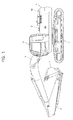
- FIG. 1 is a side view illustrating a hydraulic excavator that constitutes one embodiment of the construction machine according to the present invention.
- the construction machine according to this embodiment is the hydraulic excavator as an example, and is provided with a travel base 1 and a revolving upperstructure 2 mounted on the travel base 1.
- an operator's cab 3 is arranged at a forward position while a counterweight 4 for assuring a balance in weight is arranged at a rearward position.
- a front working mechanism useful for the digging of earth and sand or like work is attached to a forward position of the revolving upperstructure 2.
- This front working mechanism includes, for example, a boom 5 securedpivotally in an up-to-down direction to the revolving upperstructure 2, an arm 6 connected pivotally in an up-to-down direction to a free end of the boom 5, and a bucket 7 secured pivotally in an up-to-down direction to a free end of the arm 6.
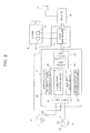
- FIG. 2 is a block diagram showing the construction of essential parts of this embodiment.
- the above-described hydraulic excavator illustrated in FIG. 1 is provided, as showninFIG. 2, with a prime mover for driving an unillustrated hydraulic pump that delivers hydraulic pressure to drive the above-mentioned front working mechanism or the like, in other words, an engine 8 and an engine controller 9 for controlling a drive of the engine 8.
- the engine 8 is further provided, in addition to a fuel injection pump 10 for injecting fuel to drive the engine 8, with an engine coolant temperature sensor 11 for detecting a temperature of engine coolant.
- a monitor camera 12 arranged on an upper part of the above-mentioned counterweight 4 illustrated in FIG. 1 for monitoring around the machine body and outputting peripheral image information as video signals, and a monitor 13 arranged in the operator' s cab 3 and capable of displaying peripheral image information based on the video signals outputted from the monitor camera 12.
- a fuel tank 14 and a residual quantity sensor 15 for detecting the residual quantity of fuel in the fuel tank 14 are also provided.
- the residual quantity sensor 15, the above-mentioned engine coolant temperature sensor 11, and the like constitute the machine information detection means that detects operation information on the hydraulic excavator, that is, machine information.
- the above-mentioned machine information and the above-mentionedperipheral image information can be selectively displayed as a normal picture on the monitor 13. For example, it is possible to selectively display both of the machine information and peripheral image information or only the machine information.
- a prime-mover start instruction device for example, an engine key switch device 16 is also provided.
- This engine key switch device 16 is equipped with a plurality of switch positions, for example, an OFF position for stopping a drive of the engine 8, an ON position for holding the engine 8 in a drivable standby state, and an S position, namely, start position for starting the engine 8.
- This embodiment is provided especially with a picture display means for displaying, for example, only peripheral image information as a picture based on video signals from the monitor camera 12 instead of the above-mentioned normal picture for the predetermined set time after a start instruction signal, specifically ON signal is outputted from the prime-mover start instruction device, that is, the engine key switch device 16 and also with the prime-mover start delay means for delaying starting of the engine 8 for the above-mentioned set time, specifically an engine start delay means.
- These picture displaymeans and engine start delaying means are included as components in a main controller 17 to be described subsequently herein.
- the above-mentioned set time is set at such a time that the operator in the operator's cab 3 can recognize peripheral image information of the hydraulic excavator, for example, information on a rearward field of vision by watching a picture of peripheral image information displayed on the monitor 13 based on video signals from the monitor camera 12.
- the above-mentioned main controller 17 is provided, as shown in FIG. 2 , with an input unit 18, a key switch signal discrimination means 20 and an output unit 24.
- the input unit 18 inputs detection signals outputted from the engine coolant temperature sensor 11, the residual quantity sensor 15 and the like, and also, an ON signal or the like outputted from the engine key switch device 16.
- the key switch signal discrimination means 20 discriminates whether or not the ON signal has been inputted from the engine key switch device 16.
- the output unit 24 outputs a signal, which corresponds to the results of processing at the main controller 17, to the engine controller 9 or monitor 13.
- This controller 17 is provided with a picture switch means 22 included in the above-mentioned picture display control means. Based on the ON signal outputted from the engine key switch 16, this picture switch means 22 switches the picture of the monitor 13 to a picture that shows only peripheral image information based on video signals from the monitor camera 12.
- This controller 17 is also provided with the memory mean, specifically a storage unit 19, a picture display time discrimination means 23, and the prime-mover start control means, specifically an engine start control means 21, all of which are included in the above-mentioned engine start delay means.
- the storage unit 19 stores the above-mentioned set time beforehand.
- the picture display time discrimination means 23 discriminates whether or not a display time of the picture of peripheral image information displayed on the monitor 13 has reached the set time stored in the storage unit 19.
- the engine start controlmeans 21 controls the engine 8 to remain disabled to start based on the ON signal outputted from the engine key switch 16, and also controls to enable starting of the engine 8 when the display time of the picture of peripheral picture information on the monitor 13 is discriminated by the picture display time discrimination means 23 to have reached the set time stored in the storage unit 19.
- FIG. 3 is a flow chart illustrating processing steps at the main controller included in the construction of essential parts shown in FIG. 2 . It is to be noted that processing is performed beforehand to store "5" as a set time in the storage unit 19 of the main controller 17.
- a start instruction signal specifically an ON signal is outputted from this engine key switch device 16.
- step S1 of FIG. 3 the routine is discriminated, as illustrated in step S1 of FIG. 3 , whether or not the ON signal from the engine key switch device 16 has been inputted. Now assuming that the ON signal has been inputted, the routine advances to step S2.
- step S2 the engine 8 is controlled to temporarily remain disabled to start by the engine start control means 21 included in the engine start delay means.
- the routine then advances to step S3.
- step S3 processing is performed by the picture switch means 22, which is included in the picture display control means, to switch the picture of the monitor 13 to a picture that shows, for example, peripheral image information based on video signals from the monitor camera 12.
- the routine then advances to step S4.
- step S4 processing is performed to add "1", which corresponds to a unit time upon conducting measurements, to a timer included in the main controller 17. The routine then advances to step S5.
- step S5 a discrimination is performed by the picture display time discrimination means 23 included in the engine start delay means as to whether or not a display time of the picture of peripheral image information on the monitor 13, said display time being an integrated value of the unit time as measured by the timer, has reached "5" or greater. If this discrimination results in "NO”, the routine returns to step S3, and the picture of peripheral image information remains displayed on the monitor 13.
- the operator in the operator's cab 3 can, therefore, confirm whether or not there is any obstruction around, especially rearward of the hydraulic excavator.
- step S5 results in "YES"
- the routine then advances to step S6.
- step 6 processing is performed by the picture switch means 22 to switch the picture of the monitor 13 from the picture of peripheral image information to the normal picture.
- the picture of the monitor 13 is switched, for example, to a picture that shows both of machine information based on a detection signals of the engine coolant temperature sensor 11 and residual quantity sensor 15 arranged in the fuel tank 14 and the above-mentioned peripheral image information based on the video signals from the monitor camera 12.
- the routine then advances to step S7.
- step S7 engine start permission control is performed, specifically the engine 8 is controlled by the engine start control means 21 into a state in which its starting is enabled.
- the routine then advances to step S8.
- step S8 it is discriminated at the main controller 17 whether or not the engine key switch device 16 shown in FIG. 2 has been manipulated to the start position (position). Now assuming, for example, that the engine key switch device 16 is in the state that it has been manipulated to the ON position, the discrimination in step S6 results in "NO", and therefore, the engine 8 is controlled to remain in a standby state in which the engine 8 can start. When the engine key switch device 16 is manipulated from such a state to the start position, the discrimination in this step S8 results in "YES", and then, the routine advances to step S9.
- step S9 processing is performed to output an engine start signal to the engine controller 9 via the output unit 24.
- a drive signal is outputted from the engine controller 9 to the fuel injector 10 so that the engine 8 starts.
- the desired work can be performed after an appropriate operation or operations to avoid the obstruction such as driving of the travel base 1, rotation of the revolving upperstructure 2 and/or changing of the spatial position of the front working mechanism is performed.
- the engine key switch device 16 is manipulated back to the OFF position after the completion of the work, the engine 8 stops.
- step S8 of FIG. 3 results in "YES” and the routine immediately advances to step S9. Therefore, the above-mentioned engine start signal is outputted to the engine controller 9, whereby the above-mentioned respective operations become feasible.
- the picture display control means including the picture switch means 22 for displaying peripheral image information as a picture on the monitor 13 for the predetermined set time after a start instruction signal, specifically an ON signal is outputted as a result of a manipulation of the engine key switch device 16; and also the engine start delay means including the storage unit 19, picture display time discrimination means 23 and engine start control means 21 for delaying starting of the engine 8 for the set time.
- the starting of the prime mover becomes feasible even when obstruction exists around the construction body.
- all work required to be performed by the hydraulic excavator including the performance of an operation or operations for the avoidance of the obstruction, can be performed, thereby making it possible to assure excellent workability.
Landscapes
- Engineering & Computer Science (AREA)
- Mining & Mineral Resources (AREA)
- Civil Engineering (AREA)
- General Engineering & Computer Science (AREA)
- Structural Engineering (AREA)
- Multimedia (AREA)
- Mechanical Engineering (AREA)
- Component Parts Of Construction Machinery (AREA)
- Closed-Circuit Television Systems (AREA)
- Operation Control Of Excavators (AREA)
Abstract
Description
- This invention relates to a construction machine such as a hydraulic excavator, in which monitoring around a machine body by a monitor camera and start control of a prime mover are associated with each other.
- Conventional technologies that associate monitoring around a vehicle or machine body with start control of a prime mover include, for example, one disclosed in
Patent Document 1. According to this conventional technology, the capturing of an image underneath a vehicle is performed when an engine start signal is outputted. In accordance with the captured image, it is automatically determined by a subtraction operation whether or not there is any obstruction underneath the vehicle. If any obstruction is determined to exist, processing is performed to prohibit starting of an engine. - Patent Document 1:
JP-A-2005-138720 - The above-mentioned conventional technology prohibits starting of the engine if any obstruction is determined to exist underneath the vehicle body, and therefore, can be hardly applied to construction machines. In the case of a construction machine, for example, a hydraulic excavator that performs digging work of earth and sand or like work, an operation or operations to rotate a revolving upperstructure, to change the spatial position of a front working mechanism and/or to drive a travel base is needed to avoid obstruction upon starting work if the obstruction exists around a machine body. If starting of an engine is prohibited as in the above-mentioned conventional technology when obstruction is determined to exist, it is, therefore, no longer possible to perform such an operation or operations to avoid the obstruction, thereby making it impossible to start work. In a work site where a hydraulic excavator is used, it is common that various materials are piled or earth and sand or the like is laid in heaps around the hydraulic excavator. If these materials, earth and sand, or the like is determined to be obstruction as in the conventional technology upon starting work, starting of an engine is prohibited so that the work cannot be started. An application of the above-mentioned conventional technology to a construction machine results in the prohibition of starting of an engine when obstruction is found by monitoring, and therefore, involves a problem that no work can be performed by the construction machine in such a situation.
- With the above-mentioned situation of the conventional technology in view, the present invention has as an object thereof the provision of a construction machine, which can surely perform the confirmation of conditions aroundamachine body upon starting work and can start a prime mover even when obstruction exists around the machine body.
- To achieve this object, the present invention provides a construction machine provided with a prime mover, a working mechanism actuatable by a drive of the prime mover, a prime-mover start instruction device for outputting a start instruction signal to enable starting of the prime mover, a machine information detection means for detecting predeterminedmachine information and outputting a detection signal, a monitor camera for monitoring around a machine body and outputting peripheral image information as video signals, and a monitor capable of selectively displaying the machine information and peripheral image information based on the detection signal outputted from the machine information detection means and the video signals outputted from the monitor camera, comprising a picture display control means for displaying the peripheral image information as a picture on the monitor for a predetermined set time after the start instruction signal is outputted from the prime-mover start instruction device, and a prime-mover start delay means for delaying starting of the prime mover for the set time.
- According to the present invention constructed as described above, when the prime-mover start instruction device is manipulated upon staring work by the working mechanism, a start instruction signal is outputted from the prime-mover start instruction device. Responsive to this start instruction signal, the picture display control means displays peripheral image information, which is basedon video signals from the monitor camera monitoring around the machine body, as a picture on the monitor for the predetermined set time after the start instruction signal is outputted from the prime-mover start instruction device. As a result, an operator of the construction machine can confirm the existence/non-existence of any obstruction around the machine body and, if there is obstruction, the operator becomes aware that the work should be started after an operation or operations are performed to a void the obstruction. During the above-mentioned set time, the starting of the prime mover is delayed by the prime-mover start delay means. After the set time has elapsed subsequent to finishing the confirmation of any obstruction around the machine body by the operator, starting of the prime mover becomes feasible. Accordingly, if obstruction exists, an operation or operations of the construction machine can be performed to avoid the obstruction and the working mechanism can then be actuated by a drive of the prime mover. It is, therefore, possible to perform predetermined work by the working mechanism even when there is obstruction around the machine body.
- As is appreciated from the foregoing, the present invention makes it possible to surely perform, upon starting work, the confirmation of conditions around the machine body based on peripheral image information displayed on the monitor by the image display control means and, even when obstruction exists around the machine body, also makes it possible to start the prime mover upon elapse of the set time subsequent to the output of a start instruction signal from the prime-mover start instruction device.
- In the present invention described above, the picture display control means may comprise a picture switch means for switching a picture of the monitor to the picture of peripheral image information based on the start instruction signal outputted from the prime-mover start instruction device; and the prime-mover start delay means may comprise a storage means for storing the set time beforehand, a picture display time discrimination means for discriminating whether or not a display time of the picture of peripheral image information displayed on the monitor has reached the set time stored in the storage means, and a prime-mover start control means for controlling the prime mover to remain disabled to start based on the start instruction signal outputted from the prime-mover start instruction device and controlling to enable starting of the prime mover when the display time of the picture of peripheral picture information on the monitor is discriminated to have reached the set time stored in the storage means.
- According to the present invention constructed as described above, when a start instruction signal is outputted from the prime-mover start instruction device, the prime mover is controlled to remain disabled to start by the prime-mover start control means of the prime-mover start delay means, and further, the picture switch means switches a picture of the monitor to a picture of peripheral image information based on the start instruction signal. This picture of peripheral image information remains displayed until a display time of the picture of peripheral image information is discriminated by the picture display time discrimination means of the prime-mover start delay means to have reached the set time stored in the storage means. By watching the picture of peripheral image information on the monitor, the operator of the construction machine can hence confirm whether or not any obstruction exists around the machine body. When the display time of the picture of peripheral imager information is discriminated by the picture display time discrimination means of the prime-mover start delay means to have reached the set time, the picture of the monitor is switched, for example, by the picture switch means to a normal picture that selectively shows machine information and peripheral image information, and further, the starting of the prime mover becomes feasible by the prime-mover start control means of the prime-mover start delay means irrespective of whether or not there is any obstruction around the machine body.
- In the present invention described above, the construction machine may comprise a hydraulic excavator. If materials, earth and sand, or the like around the machine body at the time of starting of work by the hydraulic excavator lie as obstruction, the present invention constructed as described above can perform the confirmation of the obstruction and a response operation or operations to avoid the obstruction, and therefore, can perform desired work.
- Owing to the arrangement of the picture display control means for displayingperipheral image information as a picture on the monitor for the predetermined set time after a start instruction signal is outputted from the prime-mover start instruction device and also the prime-mover start delay means for delaying starting of the prime mover for the set time, the present invention can surely perform, upon starting work, the confirmation of conditions around the machine body by the peripheral image information on the screen of the monitor the display of which is controlled by the picture display control means. It is, therefore, possible to realize the assurance of safety at the time of starting work, and after delaying processing of starting of the prime mover by the prime-mover start delay means, also to start the prime mover even when obstruction exists around the machine body. As a consequence, all work required to be performed by the construction machine, including the performance of an operation or operations for the avoidance of the obstruction, can be performed, thereby making it possible to assure excellent workability which has been hardly achievable by the conventional technology.
- A best mode for carrying out the construction machine according to the present invention will hereinafter be described based on drawings.
-
FIG. 1 is a side view illustrating a hydraulic excavator that constitutes one embodiment of the construction machine according to the present invention. As illustrated inFIG. 1 , the construction machine according to this embodiment is the hydraulic excavator as an example, and is provided with atravel base 1 and a revolvingupperstructure 2 mounted on thetravel base 1. On the revolvingupperstructure 2, an operator'scab 3 is arranged at a forward position while acounterweight 4 for assuring a balance in weight is arranged at a rearward position. To a forward position of the revolvingupperstructure 2, a front working mechanism useful for the digging of earth and sand or like work is attached. This front working mechanism includes, for example, aboom 5 securedpivotally in an up-to-down direction to the revolvingupperstructure 2, an arm 6 connected pivotally in an up-to-down direction to a free end of theboom 5, and abucket 7 secured pivotally in an up-to-down direction to a free end of the arm 6. -
FIG. 2 is a block diagram showing the construction of essential parts of this embodiment. The above-described hydraulic excavator illustrated inFIG. 1 is provided, as showninFIG. 2, with a prime mover for driving an unillustrated hydraulic pump that delivers hydraulic pressure to drive the above-mentioned front working mechanism or the like, in other words, anengine 8 and anengine controller 9 for controlling a drive of theengine 8. Theengine 8 is further provided, in addition to afuel injection pump 10 for injecting fuel to drive theengine 8, with an enginecoolant temperature sensor 11 for detecting a temperature of engine coolant. Also provided are amonitor camera 12 arranged on an upper part of the above-mentionedcounterweight 4 illustrated inFIG. 1 for monitoring around the machine body and outputting peripheral image information as video signals, and amonitor 13 arranged in the operator' scab 3 and capable of displaying peripheral image information based on the video signals outputted from themonitor camera 12. - As shown by way of example in
FIG. 2 , afuel tank 14 and aresidual quantity sensor 15 for detecting the residual quantity of fuel in thefuel tank 14 are also provided. Theresidual quantity sensor 15, the above-mentioned enginecoolant temperature sensor 11, and the like constitute the machine information detection means that detects operation information on the hydraulic excavator, that is, machine information. It is to be noted that the above-mentioned machine information and the above-mentionedperipheral image information can be selectively displayed as a normal picture on themonitor 13. For example, it is possible to selectively display both of the machine information and peripheral image information or only the machine information. - As also shown in
FIG. 2 , a prime-mover start instruction device, for example, an enginekey switch device 16 is also provided. This enginekey switch device 16 is equipped with a plurality of switch positions, for example, an OFF position for stopping a drive of theengine 8, an ON position for holding theengine 8 in a drivable standby state, and an S position, namely, start position for starting theengine 8. - This embodiment is provided especially with a picture display means for displaying, for example, only peripheral image information as a picture based on video signals from the
monitor camera 12 instead of the above-mentioned normal picture for the predetermined set time after a start instruction signal, specifically ON signal is outputted from the prime-mover start instruction device, that is, the enginekey switch device 16 and also with the prime-mover start delay means for delaying starting of theengine 8 for the above-mentioned set time, specifically an engine start delay means. These picture displaymeans and engine start delaying means are included as components in amain controller 17 to be described subsequently herein. It is to be noted that the above-mentioned set time is set at such a time that the operator in the operator'scab 3 can recognize peripheral image information of the hydraulic excavator, for example, information on a rearward field of vision by watching a picture of peripheral image information displayed on themonitor 13 based on video signals from themonitor camera 12. - The above-mentioned
main controller 17 is provided, as shown inFIG. 2 , with aninput unit 18, a key switch signal discrimination means 20 and anoutput unit 24. Theinput unit 18 inputs detection signals outputted from the enginecoolant temperature sensor 11, theresidual quantity sensor 15 and the like, and also, an ON signal or the like outputted from the enginekey switch device 16. The key switch signal discrimination means 20 discriminates whether or not the ON signal has been inputted from the enginekey switch device 16. Theoutput unit 24 outputs a signal, which corresponds to the results of processing at themain controller 17, to theengine controller 9 ormonitor 13. - This
controller 17 is provided with a picture switch means 22 included in the above-mentioned picture display control means. Based on the ON signal outputted from theengine key switch 16, this picture switch means 22 switches the picture of themonitor 13 to a picture that shows only peripheral image information based on video signals from themonitor camera 12. - This
controller 17 is also provided with the memory mean, specifically astorage unit 19, a picture display time discrimination means 23, and the prime-mover start control means, specifically an engine start control means 21, all of which are included in the above-mentioned engine start delay means. Thestorage unit 19 stores the above-mentioned set time beforehand. The picture display time discrimination means 23 discriminates whether or not a display time of the picture of peripheral image information displayed on themonitor 13 has reached the set time stored in thestorage unit 19. The engine start controlmeans 21 controls theengine 8 to remain disabled to start based on the ON signal outputted from the enginekey switch 16, and also controls to enable starting of theengine 8 when the display time of the picture of peripheral picture information on themonitor 13 is discriminated by the picture display time discrimination means 23 to have reached the set time stored in thestorage unit 19. - A description will hereinafter be made about operations of this embodiment, including processing operations to be performed at the
main controller 17.FIG. 3 is a flow chart illustrating processing steps at the main controller included in the construction of essential parts shown inFIG. 2 . It is to be noted that processing is performed beforehand to store "5" as a set time in thestorage unit 19 of themain controller 17. - When the engine
key switch device 16 is manipulated from the OFF position to, for example, the ON position upon starting work by the above-mentioned front working mechanism, a start instruction signal, specifically an ON signal is outputted from this enginekey switch device 16. - At the key switch signal discrimination means 20 in the
main controller 17, it is discriminated, as illustrated in step S1 ofFIG. 3 , whether or not the ON signal from the enginekey switch device 16 has been inputted. Now assuming that the ON signal has been inputted, the routine advances to step S2. - In this step S2, the
engine 8 is controlled to temporarily remain disabled to start by the engine start control means 21 included in the engine start delay means. The routine then advances to step S3. - In step S3, processing is performed by the picture switch means 22, which is included in the picture display control means, to switch the picture of the
monitor 13 to a picture that shows, for example, peripheral image information based on video signals from themonitor camera 12. The routine then advances to step S4. - In step S4, processing is performed to add "1", which corresponds to a unit time upon conducting measurements, to a timer included in the
main controller 17. The routine then advances to step S5. - In step S5, a discrimination is performed by the picture display time discrimination means 23 included in the engine start delay means as to whether or not a display time of the picture of peripheral image information on the
monitor 13, said display time being an integrated value of the unit time as measured by the timer, has reached "5" or greater. If this discrimination results in "NO", the routine returns to step S3, and the picture of peripheral image information remains displayed on themonitor 13. By watching the picture of peripheral image information on themonitor 13, the operator in the operator'scab 3 can, therefore, confirm whether or not there is any obstruction around, especially rearward of the hydraulic excavator. Even if the operator' s hand or the like accidentally comes into contact with a control device for the front working mechanism, a control device for thetravel base 1 or a control device for the revolvingupperstructure 2 in the operator's cab during the above-mentioned step, the hydraulic excavator is maintained safe without operation because theengine 8 is controlled to remain in the stopped state. - If the discrimination in the above-mentioned step S5 results in "YES", in other words, if the display time of the picture of peripheral image information as measured by the timer is discriminated by the picture display time discrimination means 23 to have reached the time "5" stored in the
storage unit 19, the routine then advances to step S6. - In step 6, processing is performed by the picture switch means 22 to switch the picture of the
monitor 13 from the picture of peripheral image information to the normal picture. As a result, the picture of themonitor 13 is switched, for example, to a picture that shows both of machine information based on a detection signals of the enginecoolant temperature sensor 11 andresidual quantity sensor 15 arranged in thefuel tank 14 and the above-mentioned peripheral image information based on the video signals from themonitor camera 12. The routine then advances to step S7. - In step S7, engine start permission control is performed, specifically the
engine 8 is controlled by the engine start control means 21 into a state in which its starting is enabled. The routine then advances to step S8. - In step S8, it is discriminated at the
main controller 17 whether or not the enginekey switch device 16 shown inFIG. 2 has been manipulated to the start position (position). Now assuming, for example, that the enginekey switch device 16 is in the state that it has been manipulated to the ON position, the discrimination in step S6 results in "NO", and therefore, theengine 8 is controlled to remain in a standby state in which theengine 8 can start. When the enginekey switch device 16 is manipulated from such a state to the start position, the discrimination in this step S8 results in "YES", and then, the routine advances to step S9. - In step S9, processing is performed to output an engine start signal to the
engine controller 9 via theoutput unit 24. As a result, a drive signal is outputted from theengine controller 9 to thefuel injector 10 so that theengine 8 starts. - It is, therefore, possible, for example, to immediately perform desired digging work or the like by driving the front working mechanism when the existence of obstruction is not recognized in the picture of peripheral image information on the
monitor 13. When the existence of obstruction is recognized in the picture of peripheral image information on themonitor 13, on the other hand, the desired work can be performed after an appropriate operation or operations to avoid the obstruction such as driving of thetravel base 1, rotation of the revolvingupperstructure 2 and/or changing of the spatial position of the front working mechanism is performed. When the enginekey switch device 16 is manipulated back to the OFF position after the completion of the work, theengine 8 stops. - In the foregoing, the description was made about the case in which upon starting the work, the engine
key switch device 16 was manipulated to the ON position. The enginekey switch device 16 may, however, be manipulated to the start position (S position). If manipulated to the start position as mentioned above, the discrimination in step S8 ofFIG. 3 results in "YES" and the routine immediately advances to step S9. Therefore, the above-mentioned engine start signal is outputted to theengine controller 9, whereby the above-mentioned respective operations become feasible. - According to this embodiment constructed as described above, there are provided the picture display control means including the picture switch means 22 for displaying peripheral image information as a picture on the
monitor 13 for the predetermined set time after a start instruction signal, specifically an ON signal is outputted as a result of a manipulation of the enginekey switch device 16; and also the engine start delay means including thestorage unit 19, picture display time discrimination means 23 and engine start control means 21 for delaying starting of theengine 8 for the set time. Upon starting work, it is, therefore, possible to surely perform the confirmation of conditions around the machine body by the peripheral image information in the picture of themonitor device 13 as switched by the picture switchmeans 22, and to realize the assurance of safety at the time of starting the work. After completion of the processing that delays the starting of theengine 8 by the engine start delay means, the starting of the prime mover becomes feasible even when obstruction exists around the construction body. As a consequence, all work required to be performed by the hydraulic excavator, including the performance of an operation or operations for the avoidance of the obstruction, can be performed, thereby making it possible to assure excellent workability. -
- [
FIG. 1 ] A side view illustrating a hydraulic excavator constituting one embodiment of the construction machine according to the present invention. - [
FIG. 2 ] A block diagram showing the construction of essential parts of the embodiment. - [
FIG. 3 ] A flow chart illustrating processing steps at a main controller included in the construction of essential parts as shown inFIG. 2 . -
- 1
- Travel base
- 2
- Revolving upperstructure
- 3
- Operator' s cab
- 4
- Counterweight
- 5
- Boom
- 6
- Arm
- 7
- Bucket
- 8
- Engine (prime mover)
- 9
- Engine controller
- 10
- Fuel injector
- 11
- Engine coolant temperature sensor (Machine information detection means)
- 12
- Monitor camera
- 13
- Monitor
- 14
- Fuel tank
- 15
- Residual quantity sensor (Machine information detection means)
- 16
- Engine key switch device (Prime-mover start instruction device)
- 17
- Main controller
- 18
- Input unit
- 19
- Storage unit (storage means)
- 20
- Key switch signal discrimination means
- 21
- Engine start control means (Prime-mover start control means)
- 22
- Picture switch means
- 23
- Image display time discrimination means
- 24
- Output unit
Claims (3)
- A construction machine provided with a prime mover, a working mechanism actuatable by a drive of the prime mover, a prime-mover start instruction device for outputting a start instruction signal to enable starting of the prime mover, a machine information detection means for detecting predeterminedmachine information and outputting a detection signal, a monitor camera for monitoring around a machine body and outputting peripheral image information as video signals, and a monitor capable of selectively displaying the machine information and peripheral image information based on the detection signal outputted from the machine information detection means and the video signals outputted from the monitor camera, comprising:a picture display control means for displaying the peripheral image information as a picture on the monitor for a predetermined set time after the start instruction signal is outputted from the prime-mover start instruction device; anda prime-mover start delay means for delaying starting of the prime mover for the set time.
- The construction machine according to claim 1, wherein:the picture display control means comprises a picture switch means for switching a picture of the monitor to the picture of peripheral image information based on the start instruction signal outputted from the prime-mover start instruction device; andthe prime-mover start delay means comprises:a storage means for storing the set time beforehand,a picture display time discrimination means for discriminating whether or not a display time of the picture of peripheral image information displayed on the monitor has reached the set time stored in the storage means, anda prime-mover start control means for controlling the prime mover to remain disabled to start based on the start instruction signal outputted from the prime-mover start instruction device and controlling to enable starting of the prime mover when the display time of the picture of peripheral picture information on the monitor is discriminated to have reached the set time stored in the storage means.
- The construction machine according to claim 1 or 2, which comprises a hydraulic excavator.
Applications Claiming Priority (2)
| Application Number | Priority Date | Filing Date | Title |
|---|---|---|---|
| JP2007318692A JP4885833B2 (en) | 2007-12-10 | 2007-12-10 | Construction machinery |
| PCT/JP2008/072265 WO2009075251A1 (en) | 2007-12-10 | 2008-12-08 | Construction machine |
Publications (3)
| Publication Number | Publication Date |
|---|---|
| EP2233647A1 true EP2233647A1 (en) | 2010-09-29 |
| EP2233647A4 EP2233647A4 (en) | 2013-03-20 |
| EP2233647B1 EP2233647B1 (en) | 2014-07-30 |
Family
ID=40755493
Family Applications (1)
| Application Number | Title | Priority Date | Filing Date |
|---|---|---|---|
| EP08860222.2A Not-in-force EP2233647B1 (en) | 2007-12-10 | 2008-12-08 | Construction machine |
Country Status (6)
| Country | Link |
|---|---|
| US (1) | US20100277590A1 (en) |
| EP (1) | EP2233647B1 (en) |
| JP (1) | JP4885833B2 (en) |
| KR (1) | KR101528950B1 (en) |
| CN (1) | CN101883899B (en) |
| WO (1) | WO2009075251A1 (en) |
Cited By (2)
| Publication number | Priority date | Publication date | Assignee | Title |
|---|---|---|---|---|
| EP2792798A4 (en) * | 2011-12-13 | 2016-07-27 | Volvo Constr Equip Ab | OMNIDIRECTIONAL DANGER DETECTION DEVICE FOR CONSTRUCTION APPARATUS |
| JP2018184830A (en) * | 2018-07-10 | 2018-11-22 | 住友建機株式会社 | Shovel |
Families Citing this family (5)
| Publication number | Priority date | Publication date | Assignee | Title |
|---|---|---|---|---|
| KR101078341B1 (en) * | 2009-02-12 | 2011-11-01 | 볼보 컨스트럭션 이큅먼트 에이비 | construction equipment mounting rear view apparatus |
| JP5637554B2 (en) * | 2010-06-25 | 2014-12-10 | キャタピラー エス エー アール エル | Engine starter for construction machinery |
| DE112016007308T5 (en) * | 2016-12-28 | 2019-07-04 | Komatsu Ltd. | Work vehicle and control system for work vehicle |
| JP7153595B2 (en) * | 2019-03-26 | 2022-10-14 | 日立建機株式会社 | construction machinery |
| KR20240036094A (en) * | 2022-03-29 | 2024-03-19 | 히다찌 겐끼 가부시키가이샤 | Remote operation systems of working machines and working machines |
Family Cites Families (13)
| Publication number | Priority date | Publication date | Assignee | Title |
|---|---|---|---|---|
| JP3125969B2 (en) * | 1994-12-02 | 2001-01-22 | 鹿島建設株式会社 | Target proximity detection method from moving object |
| WO2002040783A1 (en) * | 2000-11-17 | 2002-05-23 | Hitachi Construction Machinery Co., Ltd. | Display device and display controller of construction machinery |
| DE10207871A1 (en) * | 2001-03-29 | 2002-10-10 | Heidelberger Druckmasch Ag | Printing machine has controller that operates printing machine only on receiving acknowledgement that hazardous area has been examined by sensor unit |
| JP2002327469A (en) * | 2001-05-02 | 2002-11-15 | Komatsu Ltd | Peripheral safety devices in construction machinery |
| JP4310632B2 (en) * | 2003-11-07 | 2009-08-12 | 日立建機株式会社 | Construction machine display device |
| JP2005138720A (en) * | 2003-11-07 | 2005-06-02 | Denso Corp | Obstacle detection device, obstacle detection program, and storage medium |
| JP4569739B2 (en) * | 2003-11-28 | 2010-10-27 | 日立建機株式会社 | Construction machine display device |
| JP4079113B2 (en) * | 2004-04-19 | 2008-04-23 | 日立建機株式会社 | Construction machine display device |
| JP4817620B2 (en) * | 2004-07-05 | 2011-11-16 | 日立建機株式会社 | Construction machine display device |
| JP2008179940A (en) * | 2005-03-31 | 2008-08-07 | Hitachi Constr Mach Co Ltd | Work machine ambient monitoring device |
| US20070021894A1 (en) * | 2005-07-21 | 2007-01-25 | Caterpillar Inc. | Method for initiating start-up of an electrical system |
| JP5054294B2 (en) * | 2005-08-05 | 2012-10-24 | 株式会社小松製作所 | Display device mounted on work vehicle and display method of display device |
| JP2007056679A (en) * | 2005-08-22 | 2007-03-08 | Nikki Co Ltd | Engine LPG fuel supply system |
-
2007
- 2007-12-10 JP JP2007318692A patent/JP4885833B2/en not_active Expired - Fee Related
-
2008
- 2008-12-08 EP EP08860222.2A patent/EP2233647B1/en not_active Not-in-force
- 2008-12-08 US US12/746,618 patent/US20100277590A1/en not_active Abandoned
- 2008-12-08 CN CN2008801189418A patent/CN101883899B/en not_active Expired - Fee Related
- 2008-12-08 WO PCT/JP2008/072265 patent/WO2009075251A1/en not_active Ceased
- 2008-12-08 KR KR1020107015153A patent/KR101528950B1/en not_active Expired - Fee Related
Cited By (3)
| Publication number | Priority date | Publication date | Assignee | Title |
|---|---|---|---|---|
| EP2792798A4 (en) * | 2011-12-13 | 2016-07-27 | Volvo Constr Equip Ab | OMNIDIRECTIONAL DANGER DETECTION DEVICE FOR CONSTRUCTION APPARATUS |
| JP2018184830A (en) * | 2018-07-10 | 2018-11-22 | 住友建機株式会社 | Shovel |
| JP7009327B2 (en) | 2018-07-10 | 2022-01-25 | 住友建機株式会社 | Excavator |
Also Published As
| Publication number | Publication date |
|---|---|
| CN101883899A (en) | 2010-11-10 |
| CN101883899B (en) | 2012-06-06 |
| KR101528950B1 (en) | 2015-06-15 |
| EP2233647B1 (en) | 2014-07-30 |
| WO2009075251A1 (en) | 2009-06-18 |
| US20100277590A1 (en) | 2010-11-04 |
| JP2009138497A (en) | 2009-06-25 |
| JP4885833B2 (en) | 2012-02-29 |
| EP2233647A4 (en) | 2013-03-20 |
| KR20100106466A (en) | 2010-10-01 |
Similar Documents
| Publication | Publication Date | Title |
|---|---|---|
| EP2233647B1 (en) | Construction machine | |
| JP4079113B2 (en) | Construction machine display device | |
| US8917292B2 (en) | Display system for working machine | |
| JP4310632B2 (en) | Construction machine display device | |
| KR102522714B1 (en) | shovel | |
| US8847745B2 (en) | Display system for working machine | |
| EP3832029B1 (en) | Construction machine | |
| EP3205862B1 (en) | Work machine | |
| KR20050033457A (en) | Display device of construction machinery | |
| CN1621628B (en) | Display device of engineering construction machine | |
| KR102508279B1 (en) | hydraulic shovel | |
| CN117248592A (en) | Control method of working machine, control program for working machine, control system for working machine, and working machine | |
| KR20110077063A (en) | Camera mode control method of construction equipment | |
| CN121794972A (en) | construction machinery |
Legal Events
| Date | Code | Title | Description |
|---|---|---|---|
| PUAI | Public reference made under article 153(3) epc to a published international application that has entered the european phase |
Free format text: ORIGINAL CODE: 0009012 |
|
| 17P | Request for examination filed |
Effective date: 20100623 |
|
| AK | Designated contracting states |
Kind code of ref document: A1 Designated state(s): AT BE BG CH CY CZ DE DK EE ES FI FR GB GR HR HU IE IS IT LI LT LU LV MC MT NL NO PL PT RO SE SI SK TR |
|
| AX | Request for extension of the european patent |
Extension state: AL BA MK RS |
|
| DAX | Request for extension of the european patent (deleted) | ||
| A4 | Supplementary search report drawn up and despatched |
Effective date: 20130214 |
|
| RIC1 | Information provided on ipc code assigned before grant |
Ipc: E02F 9/24 20060101AFI20130208BHEP Ipc: E02F 9/20 20060101ALI20130208BHEP Ipc: B60R 1/00 20060101ALI20130208BHEP Ipc: E02F 9/26 20060101ALI20130208BHEP |
|
| GRAP | Despatch of communication of intention to grant a patent |
Free format text: ORIGINAL CODE: EPIDOSNIGR1 |
|
| INTG | Intention to grant announced |
Effective date: 20140410 |
|
| GRAS | Grant fee paid |
Free format text: ORIGINAL CODE: EPIDOSNIGR3 |
|
| GRAA | (expected) grant |
Free format text: ORIGINAL CODE: 0009210 |
|
| AK | Designated contracting states |
Kind code of ref document: B1 Designated state(s): AT BE BG CH CY CZ DE DK EE ES FI FR GB GR HR HU IE IS IT LI LT LU LV MC MT NL NO PL PT RO SE SI SK TR |
|
| REG | Reference to a national code |
Ref country code: GB Ref legal event code: FG4D |
|
| REG | Reference to a national code |
Ref country code: CH Ref legal event code: EP |
|
| REG | Reference to a national code |
Ref country code: AT Ref legal event code: REF Ref document number: 680080 Country of ref document: AT Kind code of ref document: T Effective date: 20140815 |
|
| REG | Reference to a national code |
Ref country code: IE Ref legal event code: FG4D |
|
| REG | Reference to a national code |
Ref country code: DE Ref legal event code: R096 Ref document number: 602008033639 Country of ref document: DE Effective date: 20140911 |
|
| REG | Reference to a national code |
Ref country code: AT Ref legal event code: MK05 Ref document number: 680080 Country of ref document: AT Kind code of ref document: T Effective date: 20140730 |
|
| REG | Reference to a national code |
Ref country code: NL Ref legal event code: VDEP Effective date: 20140730 |
|
| REG | Reference to a national code |
Ref country code: LT Ref legal event code: MG4D |
|
| PG25 | Lapsed in a contracting state [announced via postgrant information from national office to epo] |
Ref country code: NO Free format text: LAPSE BECAUSE OF FAILURE TO SUBMIT A TRANSLATION OF THE DESCRIPTION OR TO PAY THE FEE WITHIN THE PRESCRIBED TIME-LIMIT Effective date: 20141030 Ref country code: ES Free format text: LAPSE BECAUSE OF FAILURE TO SUBMIT A TRANSLATION OF THE DESCRIPTION OR TO PAY THE FEE WITHIN THE PRESCRIBED TIME-LIMIT Effective date: 20140730 Ref country code: PT Free format text: LAPSE BECAUSE OF FAILURE TO SUBMIT A TRANSLATION OF THE DESCRIPTION OR TO PAY THE FEE WITHIN THE PRESCRIBED TIME-LIMIT Effective date: 20141202 Ref country code: BG Free format text: LAPSE BECAUSE OF FAILURE TO SUBMIT A TRANSLATION OF THE DESCRIPTION OR TO PAY THE FEE WITHIN THE PRESCRIBED TIME-LIMIT Effective date: 20141030 Ref country code: GR Free format text: LAPSE BECAUSE OF FAILURE TO SUBMIT A TRANSLATION OF THE DESCRIPTION OR TO PAY THE FEE WITHIN THE PRESCRIBED TIME-LIMIT Effective date: 20141031 Ref country code: SE Free format text: LAPSE BECAUSE OF FAILURE TO SUBMIT A TRANSLATION OF THE DESCRIPTION OR TO PAY THE FEE WITHIN THE PRESCRIBED TIME-LIMIT Effective date: 20140730 Ref country code: LT Free format text: LAPSE BECAUSE OF FAILURE TO SUBMIT A TRANSLATION OF THE DESCRIPTION OR TO PAY THE FEE WITHIN THE PRESCRIBED TIME-LIMIT Effective date: 20140730 Ref country code: FI Free format text: LAPSE BECAUSE OF FAILURE TO SUBMIT A TRANSLATION OF THE DESCRIPTION OR TO PAY THE FEE WITHIN THE PRESCRIBED TIME-LIMIT Effective date: 20140730 |
|
| PG25 | Lapsed in a contracting state [announced via postgrant information from national office to epo] |
Ref country code: AT Free format text: LAPSE BECAUSE OF FAILURE TO SUBMIT A TRANSLATION OF THE DESCRIPTION OR TO PAY THE FEE WITHIN THE PRESCRIBED TIME-LIMIT Effective date: 20140730 Ref country code: CY Free format text: LAPSE BECAUSE OF FAILURE TO SUBMIT A TRANSLATION OF THE DESCRIPTION OR TO PAY THE FEE WITHIN THE PRESCRIBED TIME-LIMIT Effective date: 20140730 Ref country code: NL Free format text: LAPSE BECAUSE OF FAILURE TO SUBMIT A TRANSLATION OF THE DESCRIPTION OR TO PAY THE FEE WITHIN THE PRESCRIBED TIME-LIMIT Effective date: 20140730 Ref country code: IS Free format text: LAPSE BECAUSE OF FAILURE TO SUBMIT A TRANSLATION OF THE DESCRIPTION OR TO PAY THE FEE WITHIN THE PRESCRIBED TIME-LIMIT Effective date: 20141130 Ref country code: LV Free format text: LAPSE BECAUSE OF FAILURE TO SUBMIT A TRANSLATION OF THE DESCRIPTION OR TO PAY THE FEE WITHIN THE PRESCRIBED TIME-LIMIT Effective date: 20140730 Ref country code: PL Free format text: LAPSE BECAUSE OF FAILURE TO SUBMIT A TRANSLATION OF THE DESCRIPTION OR TO PAY THE FEE WITHIN THE PRESCRIBED TIME-LIMIT Effective date: 20140730 Ref country code: HR Free format text: LAPSE BECAUSE OF FAILURE TO SUBMIT A TRANSLATION OF THE DESCRIPTION OR TO PAY THE FEE WITHIN THE PRESCRIBED TIME-LIMIT Effective date: 20140730 |
|
| PG25 | Lapsed in a contracting state [announced via postgrant information from national office to epo] |
Ref country code: EE Free format text: LAPSE BECAUSE OF FAILURE TO SUBMIT A TRANSLATION OF THE DESCRIPTION OR TO PAY THE FEE WITHIN THE PRESCRIBED TIME-LIMIT Effective date: 20140730 Ref country code: CZ Free format text: LAPSE BECAUSE OF FAILURE TO SUBMIT A TRANSLATION OF THE DESCRIPTION OR TO PAY THE FEE WITHIN THE PRESCRIBED TIME-LIMIT Effective date: 20140730 Ref country code: RO Free format text: LAPSE BECAUSE OF FAILURE TO SUBMIT A TRANSLATION OF THE DESCRIPTION OR TO PAY THE FEE WITHIN THE PRESCRIBED TIME-LIMIT Effective date: 20140730 Ref country code: SK Free format text: LAPSE BECAUSE OF FAILURE TO SUBMIT A TRANSLATION OF THE DESCRIPTION OR TO PAY THE FEE WITHIN THE PRESCRIBED TIME-LIMIT Effective date: 20140730 Ref country code: DK Free format text: LAPSE BECAUSE OF FAILURE TO SUBMIT A TRANSLATION OF THE DESCRIPTION OR TO PAY THE FEE WITHIN THE PRESCRIBED TIME-LIMIT Effective date: 20140730 Ref country code: IT Free format text: LAPSE BECAUSE OF FAILURE TO SUBMIT A TRANSLATION OF THE DESCRIPTION OR TO PAY THE FEE WITHIN THE PRESCRIBED TIME-LIMIT Effective date: 20140730 |
|
| REG | Reference to a national code |
Ref country code: DE Ref legal event code: R097 Ref document number: 602008033639 Country of ref document: DE |
|
| PLBE | No opposition filed within time limit |
Free format text: ORIGINAL CODE: 0009261 |
|
| STAA | Information on the status of an ep patent application or granted ep patent |
Free format text: STATUS: NO OPPOSITION FILED WITHIN TIME LIMIT |
|
| PG25 | Lapsed in a contracting state [announced via postgrant information from national office to epo] |
Ref country code: BE Free format text: LAPSE BECAUSE OF NON-PAYMENT OF DUE FEES Effective date: 20141231 |
|
| 26N | No opposition filed |
Effective date: 20150504 |
|
| PG25 | Lapsed in a contracting state [announced via postgrant information from national office to epo] |
Ref country code: LU Free format text: LAPSE BECAUSE OF FAILURE TO SUBMIT A TRANSLATION OF THE DESCRIPTION OR TO PAY THE FEE WITHIN THE PRESCRIBED TIME-LIMIT Effective date: 20141208 |
|
| REG | Reference to a national code |
Ref country code: CH Ref legal event code: PL |
|
| GBPC | Gb: european patent ceased through non-payment of renewal fee |
Effective date: 20141208 |
|
| REG | Reference to a national code |
Ref country code: IE Ref legal event code: MM4A |
|
| REG | Reference to a national code |
Ref country code: FR Ref legal event code: ST Effective date: 20150831 |
|
| PG25 | Lapsed in a contracting state [announced via postgrant information from national office to epo] |
Ref country code: CH Free format text: LAPSE BECAUSE OF NON-PAYMENT OF DUE FEES Effective date: 20141231 Ref country code: LI Free format text: LAPSE BECAUSE OF NON-PAYMENT OF DUE FEES Effective date: 20141231 Ref country code: IE Free format text: LAPSE BECAUSE OF NON-PAYMENT OF DUE FEES Effective date: 20141208 Ref country code: GB Free format text: LAPSE BECAUSE OF NON-PAYMENT OF DUE FEES Effective date: 20141208 |
|
| PG25 | Lapsed in a contracting state [announced via postgrant information from national office to epo] |
Ref country code: FR Free format text: LAPSE BECAUSE OF NON-PAYMENT OF DUE FEES Effective date: 20141231 Ref country code: SI Free format text: LAPSE BECAUSE OF FAILURE TO SUBMIT A TRANSLATION OF THE DESCRIPTION OR TO PAY THE FEE WITHIN THE PRESCRIBED TIME-LIMIT Effective date: 20140730 |
|
| PG25 | Lapsed in a contracting state [announced via postgrant information from national office to epo] |
Ref country code: MC Free format text: LAPSE BECAUSE OF FAILURE TO SUBMIT A TRANSLATION OF THE DESCRIPTION OR TO PAY THE FEE WITHIN THE PRESCRIBED TIME-LIMIT Effective date: 20140730 |
|
| PG25 | Lapsed in a contracting state [announced via postgrant information from national office to epo] |
Ref country code: BE Free format text: LAPSE BECAUSE OF FAILURE TO SUBMIT A TRANSLATION OF THE DESCRIPTION OR TO PAY THE FEE WITHIN THE PRESCRIBED TIME-LIMIT Effective date: 20140730 Ref country code: MT Free format text: LAPSE BECAUSE OF FAILURE TO SUBMIT A TRANSLATION OF THE DESCRIPTION OR TO PAY THE FEE WITHIN THE PRESCRIBED TIME-LIMIT Effective date: 20140730 Ref country code: HU Free format text: LAPSE BECAUSE OF FAILURE TO SUBMIT A TRANSLATION OF THE DESCRIPTION OR TO PAY THE FEE WITHIN THE PRESCRIBED TIME-LIMIT; INVALID AB INITIO Effective date: 20081208 Ref country code: TR Free format text: LAPSE BECAUSE OF FAILURE TO SUBMIT A TRANSLATION OF THE DESCRIPTION OR TO PAY THE FEE WITHIN THE PRESCRIBED TIME-LIMIT Effective date: 20140730 |
|
| PGFP | Annual fee paid to national office [announced via postgrant information from national office to epo] |
Ref country code: DE Payment date: 20221102 Year of fee payment: 15 |
|
| REG | Reference to a national code |
Ref country code: DE Ref legal event code: R119 Ref document number: 602008033639 Country of ref document: DE |
|
| PG25 | Lapsed in a contracting state [announced via postgrant information from national office to epo] |
Ref country code: DE Free format text: LAPSE BECAUSE OF NON-PAYMENT OF DUE FEES Effective date: 20240702 |
|
| PG25 | Lapsed in a contracting state [announced via postgrant information from national office to epo] |
Ref country code: DE Free format text: LAPSE BECAUSE OF NON-PAYMENT OF DUE FEES Effective date: 20240702 |