EP2233613A1 - Copper electrolysis solution containing compound having specific skeleton as additive, and electrolytic copper foil produced therefrom - Google Patents
Copper electrolysis solution containing compound having specific skeleton as additive, and electrolytic copper foil produced therefrom Download PDFInfo
- Publication number
- EP2233613A1 EP2233613A1 EP10165867A EP10165867A EP2233613A1 EP 2233613 A1 EP2233613 A1 EP 2233613A1 EP 10165867 A EP10165867 A EP 10165867A EP 10165867 A EP10165867 A EP 10165867A EP 2233613 A1 EP2233613 A1 EP 2233613A1
- Authority
- EP
- European Patent Office
- Prior art keywords
- compound
- copper foil
- copper
- group
- electrolytic
- Prior art date
- Legal status (The legal status is an assumption and is not a legal conclusion. Google has not performed a legal analysis and makes no representation as to the accuracy of the status listed.)
- Granted
Links
- RYGMFSIKBFXOCR-UHFFFAOYSA-N Copper Chemical compound [Cu] RYGMFSIKBFXOCR-UHFFFAOYSA-N 0.000 title claims abstract description 91
- 150000001875 compounds Chemical class 0.000 title claims abstract description 76
- 239000010949 copper Substances 0.000 title claims abstract description 52
- 229910052802 copper Inorganic materials 0.000 title claims abstract description 49
- 239000011889 copper foil Substances 0.000 title claims abstract description 42
- 239000000654 additive Substances 0.000 title claims abstract description 18
- 230000000996 additive effect Effects 0.000 title claims abstract description 12
- 238000005868 electrolysis reaction Methods 0.000 title description 4
- 239000008151 electrolyte solution Substances 0.000 claims abstract description 37
- 239000000758 substrate Substances 0.000 claims abstract description 19
- 238000004519 manufacturing process Methods 0.000 claims abstract description 15
- 239000004593 Epoxy Substances 0.000 claims abstract description 11
- 230000003746 surface roughness Effects 0.000 claims abstract description 10
- 125000003700 epoxy group Chemical group 0.000 claims abstract description 8
- XLYOFNOQVPJJNP-UHFFFAOYSA-N water Substances O XLYOFNOQVPJJNP-UHFFFAOYSA-N 0.000 claims abstract description 6
- 238000007259 addition reaction Methods 0.000 claims abstract description 5
- 238000000034 method Methods 0.000 claims description 14
- 150000002898 organic sulfur compounds Chemical class 0.000 claims description 11
- ABLZXFCXXLZCGV-UHFFFAOYSA-N phosphonic acid group Chemical class P(O)(O)=O ABLZXFCXXLZCGV-UHFFFAOYSA-N 0.000 claims description 8
- 229910052783 alkali metal Chemical class 0.000 claims description 6
- 229910052739 hydrogen Inorganic materials 0.000 claims description 6
- 239000001257 hydrogen Substances 0.000 claims description 6
- NAWXUBYGYWOOIX-SFHVURJKSA-N (2s)-2-[[4-[2-(2,4-diaminoquinazolin-6-yl)ethyl]benzoyl]amino]-4-methylidenepentanedioic acid Chemical compound C1=CC2=NC(N)=NC(N)=C2C=C1CCC1=CC=C(C(=O)N[C@@H](CC(=C)C(O)=O)C(O)=O)C=C1 NAWXUBYGYWOOIX-SFHVURJKSA-N 0.000 claims description 4
- LSNNMFCWUKXFEE-UHFFFAOYSA-M Bisulfite Chemical compound OS([O-])=O LSNNMFCWUKXFEE-UHFFFAOYSA-M 0.000 claims description 4
- RTZKZFJDLAIYFH-UHFFFAOYSA-N ether Substances CCOCC RTZKZFJDLAIYFH-UHFFFAOYSA-N 0.000 claims description 4
- 125000000542 sulfonic acid group Chemical group 0.000 claims description 4
- 239000000126 substance Substances 0.000 claims description 3
- UFHFLCQGNIYNRP-UHFFFAOYSA-N Hydrogen Chemical compound [H][H] UFHFLCQGNIYNRP-UHFFFAOYSA-N 0.000 claims description 2
- 150000001340 alkali metals Chemical class 0.000 claims description 2
- 125000002947 alkylene group Chemical group 0.000 claims description 2
- 150000003863 ammonium salts Chemical group 0.000 claims description 2
- 125000004432 carbon atom Chemical group C* 0.000 claims description 2
- 150000002431 hydrogen Chemical group 0.000 claims description 2
- 125000004435 hydrogen atom Chemical group [H]* 0.000 claims description 2
- 238000007747 plating Methods 0.000 abstract description 17
- 238000000059 patterning Methods 0.000 abstract description 9
- 230000015572 biosynthetic process Effects 0.000 description 25
- 238000003786 synthesis reaction Methods 0.000 description 25
- 239000010410 layer Substances 0.000 description 24
- MWKFXSUHUHTGQN-UHFFFAOYSA-N decan-1-ol Chemical compound CCCCCCCCCCO MWKFXSUHUHTGQN-UHFFFAOYSA-N 0.000 description 12
- 230000000052 comparative effect Effects 0.000 description 8
- 239000003822 epoxy resin Substances 0.000 description 7
- 229920000647 polyepoxide Polymers 0.000 description 7
- 239000002994 raw material Substances 0.000 description 6
- 239000011888 foil Substances 0.000 description 5
- 229910006069 SO3H Inorganic materials 0.000 description 4
- 238000001460 carbon-13 nuclear magnetic resonance spectrum Methods 0.000 description 4
- 239000004020 conductor Substances 0.000 description 4
- 230000007547 defect Effects 0.000 description 4
- 238000005530 etching Methods 0.000 description 3
- 229910052751 metal Inorganic materials 0.000 description 3
- 239000002184 metal Substances 0.000 description 3
- 229920001721 polyimide Polymers 0.000 description 3
- PXHVJJICTQNCMI-UHFFFAOYSA-N Nickel Chemical compound [Ni] PXHVJJICTQNCMI-UHFFFAOYSA-N 0.000 description 2
- QAOWNCQODCNURD-UHFFFAOYSA-N Sulfuric acid Chemical compound OS(O)(=O)=O QAOWNCQODCNURD-UHFFFAOYSA-N 0.000 description 2
- 239000011248 coating agent Substances 0.000 description 2
- 239000011247 coating layer Substances 0.000 description 2
- 238000000576 coating method Methods 0.000 description 2
- 239000002659 electrodeposit Substances 0.000 description 2
- 239000003292 glue Substances 0.000 description 2
- 239000007788 liquid Substances 0.000 description 2
- 239000000203 mixture Substances 0.000 description 2
- UMGDCJDMYOKAJW-UHFFFAOYSA-N thiourea Chemical compound NC(N)=S UMGDCJDMYOKAJW-UHFFFAOYSA-N 0.000 description 2
- VEPOHXYIFQMVHW-XOZOLZJESA-N 2,3-dihydroxybutanedioic acid (2S,3S)-3,4-dimethyl-2-phenylmorpholine Chemical compound OC(C(O)C(O)=O)C(O)=O.C[C@H]1[C@@H](OCCN1C)c1ccccc1 VEPOHXYIFQMVHW-XOZOLZJESA-N 0.000 description 1
- VYZAMTAEIAYCRO-UHFFFAOYSA-N Chromium Chemical compound [Cr] VYZAMTAEIAYCRO-UHFFFAOYSA-N 0.000 description 1
- 229910000531 Co alloy Inorganic materials 0.000 description 1
- 229910000881 Cu alloy Inorganic materials 0.000 description 1
- 229910000990 Ni alloy Inorganic materials 0.000 description 1
- 229910018828 PO3H2 Inorganic materials 0.000 description 1
- PCNDJXKNXGMECE-UHFFFAOYSA-N Phenazine Natural products C1=CC=CC2=NC3=CC=CC=C3N=C21 PCNDJXKNXGMECE-UHFFFAOYSA-N 0.000 description 1
- 239000002202 Polyethylene glycol Substances 0.000 description 1
- 229920002873 Polyethylenimine Polymers 0.000 description 1
- 239000004721 Polyphenylene oxide Substances 0.000 description 1
- XSQUKJJJFZCRTK-UHFFFAOYSA-N Urea Natural products NC(N)=O XSQUKJJJFZCRTK-UHFFFAOYSA-N 0.000 description 1
- 230000002378 acidificating effect Effects 0.000 description 1
- 239000000853 adhesive Substances 0.000 description 1
- 230000001070 adhesive effect Effects 0.000 description 1
- 239000003513 alkali Substances 0.000 description 1
- OEERIBPGRSLGEK-UHFFFAOYSA-N carbon dioxide;methanol Chemical compound OC.O=C=O OEERIBPGRSLGEK-UHFFFAOYSA-N 0.000 description 1
- 239000001913 cellulose Substances 0.000 description 1
- 229920002678 cellulose Polymers 0.000 description 1
- 238000006243 chemical reaction Methods 0.000 description 1
- VNNRSPGTAMTISX-UHFFFAOYSA-N chromium nickel Chemical compound [Cr].[Ni] VNNRSPGTAMTISX-UHFFFAOYSA-N 0.000 description 1
- 238000003776 cleavage reaction Methods 0.000 description 1
- 229910017052 cobalt Inorganic materials 0.000 description 1
- 239000010941 cobalt Substances 0.000 description 1
- GUTLYIVDDKVIGB-UHFFFAOYSA-N cobalt atom Chemical compound [Co] GUTLYIVDDKVIGB-UHFFFAOYSA-N 0.000 description 1
- 239000002826 coolant Substances 0.000 description 1
- 238000001816 cooling Methods 0.000 description 1
- 238000005336 cracking Methods 0.000 description 1
- 230000007423 decrease Effects 0.000 description 1
- 238000010586 diagram Methods 0.000 description 1
- WIYCQLLGDNXIBA-UHFFFAOYSA-L disodium;3-(3-sulfonatopropyldisulfanyl)propane-1-sulfonate Chemical compound [Na+].[Na+].[O-]S(=O)(=O)CCCSSCCCS([O-])(=O)=O WIYCQLLGDNXIBA-UHFFFAOYSA-L 0.000 description 1
- -1 disulfide disodium salt Chemical class 0.000 description 1
- 239000000975 dye Substances 0.000 description 1
- 230000000694 effects Effects 0.000 description 1
- 230000005611 electricity Effects 0.000 description 1
- 238000009713 electroplating Methods 0.000 description 1
- 230000001788 irregular Effects 0.000 description 1
- 238000010030 laminating Methods 0.000 description 1
- 238000002156 mixing Methods 0.000 description 1
- 229910001120 nichrome Inorganic materials 0.000 description 1
- 229910052759 nickel Inorganic materials 0.000 description 1
- 238000000399 optical microscopy Methods 0.000 description 1
- 230000002093 peripheral effect Effects 0.000 description 1
- 229920000570 polyether Polymers 0.000 description 1
- 229920001223 polyethylene glycol Polymers 0.000 description 1
- 229920001451 polypropylene glycol Polymers 0.000 description 1
- 230000007017 scission Effects 0.000 description 1
- 239000011734 sodium Substances 0.000 description 1
- 239000000243 solution Substances 0.000 description 1
- 238000004544 sputter deposition Methods 0.000 description 1
- 238000004381 surface treatment Methods 0.000 description 1
Images


Classifications
-
- C—CHEMISTRY; METALLURGY
- C25—ELECTROLYTIC OR ELECTROPHORETIC PROCESSES; APPARATUS THEREFOR
- C25D—PROCESSES FOR THE ELECTROLYTIC OR ELECTROPHORETIC PRODUCTION OF COATINGS; ELECTROFORMING; APPARATUS THEREFOR
- C25D1/00—Electroforming
- C25D1/04—Wires; Strips; Foils
-
- C—CHEMISTRY; METALLURGY
- C25—ELECTROLYTIC OR ELECTROPHORETIC PROCESSES; APPARATUS THEREFOR
- C25D—PROCESSES FOR THE ELECTROLYTIC OR ELECTROPHORETIC PRODUCTION OF COATINGS; ELECTROFORMING; APPARATUS THEREFOR
- C25D3/00—Electroplating: Baths therefor
- C25D3/02—Electroplating: Baths therefor from solutions
- C25D3/38—Electroplating: Baths therefor from solutions of copper
Definitions
- the present invention relates to a copper electrolytic solution used in manufacturing electrolytic copper foils and 2-layer flexible substrates and other printed wiring boards, and relates particularly to a copper electrolytic solution used in manufacturing electrolytic copper foils with excellent elongation and tensile strength that allow fine patterning and 2-layer flexible substrates.
- An electrolytic copper foil is generally produced as follows.
- a rotating metal cathode drum with a polished surface is used along with an insoluble metal anode that surrounds said cathode drum and is disposed at a position substantially corresponding to the lower half of said cathode drum, a copper electrolytic solution is allowed to flow between the cathode drum and the anode, a potential differential is provided between these to electrodeposit copper to the cathode drum, and the electrodeposited copper is peeled away from the cathode drum at the point of reaching a specific thickness, so that a copper foil is produced continuously.
- a copper foil obtained in this way is generally called a raw foil, and after this it is subjected to a number of surface treatments and used for printed wiring boards and so forth.
- Fig. 1 is a simplified diagram of a conventional apparatus for producing a copper foil.
- This electrolytic copper foil production apparatus has a cathode drum 1 installed in an electrolysis bath containing electrolytic solution.
- This cathode drum 1 is designed to rotate while being partially submerged (substantially the lower half) in the electrolytic solution.
- An insoluble anode 2 is provided so as to surround the outer peripheral lower half of this cathode drum 1.
- a specific gap 3 is maintained between the cathode drum 1 and the anode 2, and an electrolytic solution is allowed to flow through this gap.
- Two anode plates are disposed in the apparatus shown in Fig. 1 .
- the electrolytic solution is supplied from below, and this electrolytic solution goes through the gap 3 between the cathode drum 1 and the anode 2, overflows from the top edge of the anode 2, and is then recirculated.
- a rectifier is interposed between the cathode drum 1 and the anode 2 so that a specific voltage can be maintained between the two components.
- the thickness of the copper electrodeposited from the electrolytic solution increases.
- this raw foil 4 is peeled away and continuously taken up.
- a raw foil produced in this manner is adjusted for thickness by varying the distance between the cathode drum 1 and the anode 2, the flow rate of the supplied electrolytic solution, or the amount of electricity supplied.
- a copper foil produced with an electrolytic copper foil producing apparatus such as this has a mirror surface on the side touching the cathode drum, but the opposite side is a rough surface with bumps and pits. Problems encountered with ordinary electrolysis are that the bumps and pits on the rough side are severe, undercutting tends to occur during etching, and fine patterning is difficult.
- the properties required of copper foils for printed wiring boards include not only elongation at room temperature but also elongation properties to prevent cracking due to temperature stress, as well as high tensile stress to maintain the dimensional stability of the printed wiring board.
- 2-layer flexible substrates have gained attention as substrates for preparing flexible wiring boards. Because in a 2-layer flexible substrate a copper conductor layer is provided directly on an insulating film without an adhesive, the substrate itself can advantageously be kept thin and the thickness of the copper conductor layer can be adjusted at will before adhesion.
- the normal method of manufacturing such a 2-layer flexible substrate is to form an underlying metallic layer by dry plating on the insulating film, and then electroplating copper on top.
- the underlying metallic layer obtained in this way contains numerous pinholes, resulting in exposure of the insulating film, and in the case of a thin copper conductor layer the areas exposed by the pinholes are not filled in and pinholes occur on the surface of the copper conductor layer, leading to wiring defects.
- Patent Document 1 for example describes a 2-layer flexible substrate manufacturing method in which an underlying metallic layer is formed on an insulating film by a dry plating process, a primary electrolytic copper plating coating layer is formed on the underlying metallic layer and treated with an alkali solution, after which an electroless copper plating coating is adhered, and finally a secondary electrolytic copper plating coating layer is formed.
- this method involves complex steps.
- Patent Document 1 Japanese Patent Publication No. H10-193505
- the inventors discovered that an electrolytic copper foil with excellent elongation and tensile strength that allows fine patterning and a 2-layer flexible substrate having a uniform copper plating without pinholes could be obtained by adding to the electrolytic solution an additive optimal for obtaining a low profile.
- an electrolytic copper foil with excellent elongation and tensile strength that allows fine patterning can be obtained by electrolysis using a copper electrolytic solution containing a compound with a specific skeleton in an electrolytic copper foil manufacturing method in which a copper electrolytic solution is made to flow between a cathode drum and an anode to electrodeposit copper on the cathode drum, after which the electrodeposited copper foil is peeled from the cathode drum to manufacture a continuous copper foil.
- a 2-layer flexible substrate having a uniform copper plating layer without pinholes could be obtained by first forming an underlying metal layer on an insulating film by dry plating using at least one selected from the group consisting of nickel, nickel alloy, chrome, cobalt, cobalt alloy, copper and copper alloy, and then plating using a copper electrolytic solution containing a compound having a specific skeleton.
- the present invention consists of the following.
- a copper electrolytic solution according to (1) or (2) above, wherein the aforementioned compound having a specific skeleton includes any of compounds represented by chemical formulae (2) through (9) below:
- n is an integer of 1 to 5.
- n is an integer of 1 to 22.
- n is an integer of 1 to 3.
- the copper electrolytic solution of the present invention having a compound with a specific skeleton and also an organic sulfur compound added thereto is extremely effective for lowering the profile of the resulting electrolytic copper foil and 2-layer flexible substrate, effectively maintains elongation properties in the copper foil, and also provides high tensile strength.
- the compound with the specific skeleton represented by General Formula (1) above which is obtained by an addition reaction in which water is added to a compound having in the molecule one or more epoxy groups, be present in the electrolytic solution.
- the compound with the specific skeleton represented by General Formula (1) above is synthesized by the addition reaction represented by the following reaction formula. That is, it can be manufactured by mixing a compound having one or more epoxy groups in the molecule with water and reacting them for about 10 minutes through 48 hours at 50 through 100°C:
- A is an epoxy residue and n is an integer of 1 or more.
- the compound having a specific skeleton is preferably a compound having a linear ether bond in epoxy compound residue A.
- a compound having one of the structural formulae (2) through (9) below is preferred as the compound having a linear ether bond in epoxy compound residue A, and in formulae (2) through (9) epoxy compound residue A is as follows:
- n is an integer of 1 to 5.
- n is an integer of 1 to 22.
- n is an integer of 1 to 3.
- organic sulfur compound is preferably added to the aforementioned copper electrolytic solution.
- the organic sulfur compound is preferably a compound having as its structural formula General Formula (10) or (11) above.
- the following are examples of the organic sulfur compound represented by General Formula (10) above, and can be used by preference.
- the ratio of the aforementioned compound having a specific skeleton to the organic sulfur compound in the copper electrolytic solution is preferably between 1:50 and 100:1 or more preferably between 1:10 and 50:1 by weight.
- the concentration of the compound having a specific skeleton in the copper electrolytic solution is preferably 1 through 1000 ppm or more preferably 1 through 200 ppm.
- the copper electrolytic solution of the present invention can contain as additives those used in ordinary acidic copper electrolytic solutions in addition to the aforementioned compound having a specific skeleton and organic sulfur compound, and known additives such as polyethylene glycol, polypropylene glycol and other polyether compounds, polyethylenimine, phenazine dye, glue, cellulose and the like can be added.
- a plating temperature of 50 through o 65°C and a current density of 40 through 150 A/dm 2 is preferred for copper foil manufacture, while in the case of a 2-layer flexible substrate a plating temperature of 25 through 60°C and a current density of 1 through 50 A/cm 2 is preferred.
- a copper clad laminate obtained by laminating the electrolytic copper foil of the present invention is a copper clad laminate with excellent elongation and tensile strength.
- the 13 C-NMR spectrum of the resulting compound is shown in Figure 2 .
- the 13 C-NMR spectrum of the raw material epoxy resin (Denacol EX-521, manufactured by Nagase Chemitex Corp.) is also shown for comparison in Figure 3 .
- peaks at 52 ppm and 45 ppm attributed to the epoxy groups disappeared from the resulting compound and this indicates the cleavage of the epoxy groups.
- the surface roughness Rz ( ⁇ m) of the resulting electrolytic copper foils was measured in accordance with JIS B 0601 and the elongation (%) at room temperature and the tensile strength (kgf/mm 2 ) at room temperature in accordance with IPC-TM650. The results are shown in Table 1. [Table 1] Additives (ppm) Rz ( ⁇ m) Room temp. elongation (%) Room temp.
- Example 1 50 0 50 0 0 0 0 0 1.70 6.20 58.1
- Example 2 50 0 0 50 0 0 0 0 1.68 5.40 55.5
- Example 3 50 0 0 0 50 0 0 1.55 6.11 59.2
- Example 4 50 0 0 0 0 50 0 0 1.72 5.50 62.0
- Example 5 50 0 0 0 0 0 50 0 1.85 5.20 52.0
- Example 6 50 0 0 0 0 0 0 0 50 1.95 6.03 58.6
- Example 7 0 50 50 0 00 0 0 0 1.68 6.10 57.5
- Example 8 0 50 0 50 0 0 0 0 0 1.65 5.52 55.5
- Example 9 0 50 0 0 50 0 0 50 0 0 0 0 1.58 6.10 61.0
- Example 10 0 50 0 0 0 0 50 0 0 1.90 5.35 62.5
- Polyimide films were electroplated under the following plating conditions to have roughly a 9 ⁇ m thick copper coating.
- the additives were added in the amounts shown in Table 2.
- Flow velocity 190 r.p.m.
- the surface roughness Rz ( ⁇ m) (10-point average roughness) and surface roughness Ra ( ⁇ m) (arithmetic average roughness) of each of the obtained 2-layer flexible substrates were measured in accordance with JIS B 0601. The planting surface was also observed for plating defects by optical microscopy and SEM. The results are shown in Table 2.
Landscapes
- Chemical & Material Sciences (AREA)
- Engineering & Computer Science (AREA)
- Chemical Kinetics & Catalysis (AREA)
- Electrochemistry (AREA)
- Materials Engineering (AREA)
- Metallurgy (AREA)
- Organic Chemistry (AREA)
- Electroplating And Plating Baths Therefor (AREA)
- Laminated Bodies (AREA)
- Parts Printed On Printed Circuit Boards (AREA)
- Electroplating Methods And Accessories (AREA)
Abstract
Description
- The present invention relates to a copper electrolytic solution used in manufacturing electrolytic copper foils and 2-layer flexible substrates and other printed wiring boards, and relates particularly to a copper electrolytic solution used in manufacturing electrolytic copper foils with excellent elongation and tensile strength that allow fine patterning and 2-layer flexible substrates.
- An electrolytic copper foil is generally produced as follows. A rotating metal cathode drum with a polished surface is used along with an insoluble metal anode that surrounds said cathode drum and is disposed at a position substantially corresponding to the lower half of said cathode drum, a copper electrolytic solution is allowed to flow between the cathode drum and the anode, a potential differential is provided between these to electrodeposit copper to the cathode drum, and the electrodeposited copper is peeled away from the cathode drum at the point of reaching a specific thickness, so that a copper foil is produced continuously.
- A copper foil obtained in this way is generally called a raw foil, and after this it is subjected to a number of surface treatments and used for printed wiring boards and so forth.
-
Fig. 1 is a simplified diagram of a conventional apparatus for producing a copper foil. This electrolytic copper foil production apparatus has acathode drum 1 installed in an electrolysis bath containing electrolytic solution. Thiscathode drum 1 is designed to rotate while being partially submerged (substantially the lower half) in the electrolytic solution. - An
insoluble anode 2 is provided so as to surround the outer peripheral lower half of thiscathode drum 1. Aspecific gap 3 is maintained between thecathode drum 1 and theanode 2, and an electrolytic solution is allowed to flow through this gap. Two anode plates are disposed in the apparatus shown inFig. 1 . - With the apparatus in
Fig. 1 , the electrolytic solution is supplied from below, and this electrolytic solution goes through thegap 3 between thecathode drum 1 and theanode 2, overflows from the top edge of theanode 2, and is then recirculated. A rectifier is interposed between thecathode drum 1 and theanode 2 so that a specific voltage can be maintained between the two components. - As the
cathode drum 1 rotates, the thickness of the copper electrodeposited from the electrolytic solution increases. When at least a certain thickness is reached, thisraw foil 4 is peeled away and continuously taken up. A raw foil produced in this manner is adjusted for thickness by varying the distance between thecathode drum 1 and theanode 2, the flow rate of the supplied electrolytic solution, or the amount of electricity supplied. - A copper foil produced with an electrolytic copper foil producing apparatus such as this has a mirror surface on the side touching the cathode drum, but the opposite side is a rough surface with bumps and pits. Problems encountered with ordinary electrolysis are that the bumps and pits on the rough side are severe, undercutting tends to occur during etching, and fine patterning is difficult.
- On the one hand, as the density on printed wiring boards has steadily risen, there has more recently been a need for a copper foil that can be more finely patterned as circuit width decreases and multilayer circuits are produced. This fine patterning requires a copper foil that has a good etching rate and uniform solubility, that is, a copper foil with excellent etching characteristics.
- Meanwhile, the properties required of copper foils for printed wiring boards include not only elongation at room temperature but also elongation properties to prevent cracking due to temperature stress, as well as high tensile stress to maintain the dimensional stability of the printed wiring board.
- = However, a copper foil with a highly irregular rough surface is wholly unsuited to fine patterning as described above. Ways are therefore being studied on lowering the profile of the rough surface. It is known that the profile can be lowered by adding large quantities of glue or thiourea to the electrolytic solution.
However, the problem with such additives is that they dramatically lower the elongation percentage, greatly detracting from the foil's properties as a copper foil for printed wiring boards. - 2-layer flexible substrates have gained attention as substrates for preparing flexible wiring boards. Because in a 2-layer flexible substrate a copper conductor layer is provided directly on an insulating film without an adhesive, the substrate itself can advantageously be kept thin and the thickness of the copper conductor layer can be adjusted at will before adhesion. The normal method of manufacturing such a 2-layer flexible substrate is to form an underlying metallic layer by dry plating on the insulating film, and then electroplating copper on top. However, the underlying metallic layer obtained in this way contains numerous pinholes, resulting in exposure of the insulating film, and in the case of a thin copper conductor layer the areas exposed by the pinholes are not filled in and pinholes occur on the surface of the copper conductor layer, leading to wiring defects. As a means of solving this problem,
Patent Document 1 for example describes a 2-layer flexible substrate manufacturing method in which an underlying metallic layer is formed on an insulating film by a dry plating process, a primary electrolytic copper plating coating layer is formed on the underlying metallic layer and treated with an alkali solution, after which an electroless copper plating coating is adhered, and finally a secondary electrolytic copper plating coating layer is formed. However, this method involves complex steps.
Patent Document 1: Japanese Patent Publication No.H10-193505 - It is an object of the present invention to provide a low profile electrolytic copper foil with low surface roughness at the rough surface side (opposite side from the glossy side) in the electrolytic copper foil manufacture using a cathode drums, and in particular to provide an electrolytic copper foil with excellent elongation and tensile strength that allows fine patterning.
Another object is to provide a copper electrolytic solution capable of uniform copper plating without pinholes on a 2-layer flexible substrate. - The inventors discovered that an electrolytic copper foil with excellent elongation and tensile strength that allows fine patterning and a 2-layer flexible substrate having a uniform copper plating without pinholes could be obtained by adding to the electrolytic solution an additive optimal for obtaining a low profile.
- Based on this finding, the inventors perfected the present invention upon discovering that an electrolytic copper foil with excellent elongation and tensile strength that allows fine patterning can be obtained by electrolysis using a copper electrolytic solution containing a compound with a specific skeleton in an electrolytic copper foil manufacturing method in which a copper electrolytic solution is made to flow between a cathode drum and an anode to electrodeposit copper on the cathode drum, after which the electrodeposited copper foil is peeled from the cathode drum to manufacture a continuous copper foil. The inventors also discovered that in a method for manufacturing a 2-layer flexible substrate, a 2-layer flexible substrate having a uniform copper plating layer without pinholes could be obtained by first forming an underlying metal layer on an insulating film by dry plating using at least one selected from the group consisting of nickel, nickel alloy, chrome, cobalt, cobalt alloy, copper and copper alloy, and then plating using a copper electrolytic solution containing a compound having a specific skeleton.
- That is, the present invention consists of the following.
- (1) A copper electrolytic solution containing as an additive a compound having a specific skeleton represented by General Formula (1) below, which is obtained by an addition reaction in which water is added to a compound having in a molecule at least one epoxy group:

- (2) The copper electrolytic solution according to (1) above, wherein the epoxy compound residue A of the aforementioned compound having a specific skeleton has a linear ether bond.
- (3) A copper electrolytic solution according to (1) or (2) above, wherein the aforementioned compound having a specific skeleton includes any of compounds represented by chemical formulae (2) through (9) below:

-

-

-

-


-

-

-

- (4) The copper electrolytic solution according to any one of (1) through (3) above, wherein the aforementioned copper electrolytic solution contains an organic sulfur compound.
- (5) The copper electrolytic solution according to (4) above, wherein the aforementioned organic sulfur compound is a compound represented by General Formula (10) or (11) below:
X-R1-(s)n-R2-Y (10)
R4-S-R3-SO3Z (11)
wherein, in general formulae (10) and (11), R1, R2 and R3 are alkylene groups with 1 through 8 carbon atoms, R4 is selected from the group consisting of hydrogen and

- (6) An electrolytic copper foil manufactured using the copper electrolytic solution according to any one of (1) through (5) above.
- (7) A copper clad laminate formed using the electrolytic copper foil according to (6) above.
- (8) A printed wiring board manufactured using the copper electrolytic solution according to any one of (1) through (5) above.
- (9) A printed wiring board wherein the printed wiring board according to (8) above is a 2-layer flexible substrate.
- The copper electrolytic solution of the present invention having a compound with a specific skeleton and also an organic sulfur compound added thereto is extremely effective for lowering the profile of the resulting electrolytic copper foil and 2-layer flexible substrate, effectively maintains elongation properties in the copper foil, and also provides high tensile strength.
- In the present invention, it is vital that the compound with the specific skeleton represented by General Formula (1) above, which is obtained by an addition reaction in which water is added to a compound having in the molecule one or more epoxy groups, be present in the electrolytic solution.
The compound with the specific skeleton represented by General Formula (1) above is synthesized by the addition reaction represented by the following reaction formula. That is, it can be manufactured by mixing a compound having one or more epoxy groups in the molecule with water and reacting them for about 10 minutes through 48 hours at 50 through 100°C: -


- The compound having a specific skeleton is preferably a compound having a linear ether bond in epoxy compound residue A. A compound having one of the structural formulae (2) through (9) below is preferred as the compound having a linear ether bond in epoxy compound residue A, and in formulae (2) through (9) epoxy compound residue A is as follows:
-

-


-

-


-

-


-

-

- An organic sulfur compound is preferably added to the aforementioned copper electrolytic solution. The organic sulfur compound is preferably a compound having as its structural formula General Formula (10) or (11) above.
The following are examples of the organic sulfur compound represented by General Formula (10) above, and can be used by preference.
H2O3P-(CH2)3-S-S-(CH2)3-PO3H2
HO3S-(CH2)4-S-S-(CH2)4-SO3H
NaO3S-(CH2)3-S-S-(CH2)3-SO3Na
HO3S-(CH2)2-S-S-(CH2)2-SO3H
CH3-S-S-CH2-SO3H
NaO3S-(CH2)3-S-S-S-(CH2)3-SO3Na
(CH3)2CH-S-S-(CH2)2-SO3H - The following are examples of the organic sulfur compound represented by General Formula (11) above, and can be used by preference.
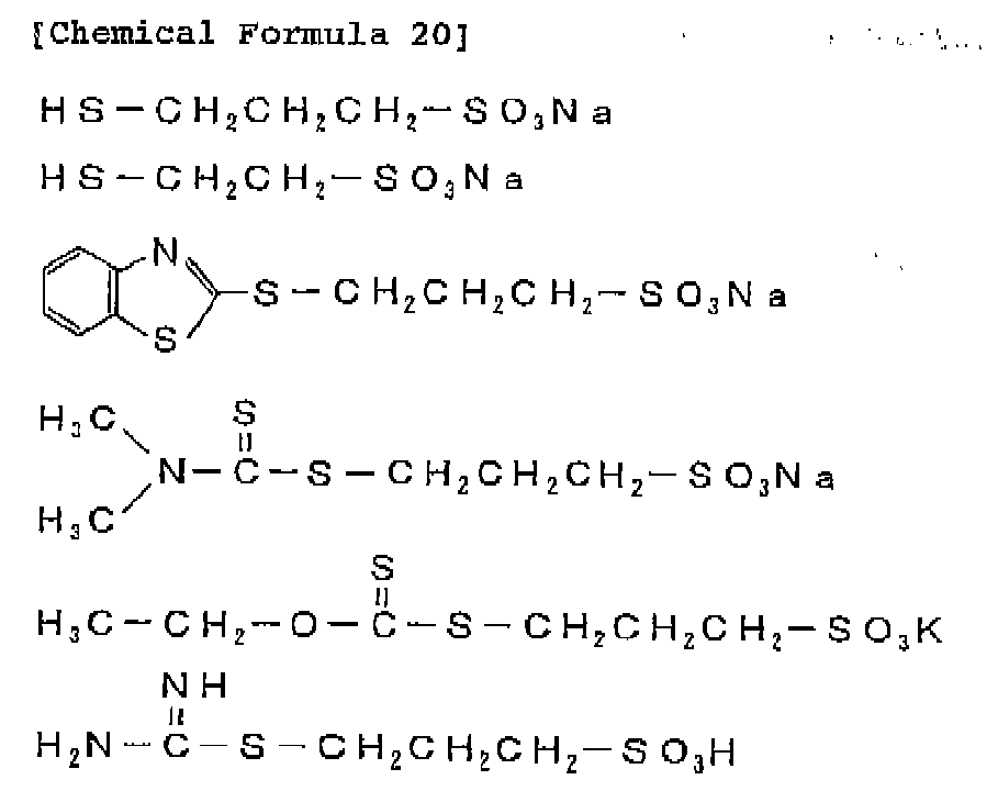
- The ratio of the aforementioned compound having a specific skeleton to the organic sulfur compound in the copper electrolytic solution is preferably between 1:50 and 100:1 or more preferably between 1:10 and 50:1 by weight. The concentration of the compound having a specific skeleton in the copper electrolytic solution is preferably 1 through 1000 ppm or more preferably 1 through 200 ppm.
- The copper electrolytic solution of the present invention can contain as additives those used in ordinary acidic copper electrolytic solutions in addition to the aforementioned compound having a specific skeleton and organic sulfur compound, and known additives such as polyethylene glycol, polypropylene glycol and other polyether compounds, polyethylenimine, phenazine dye, glue, cellulose and the like can be added.
- For the plating conditions, a plating temperature of 50 through o 65°C and a current density of 40 through 150 A/dm2 is preferred for copper foil manufacture, while in the case of a 2-layer flexible substrate a plating temperature of 25 through 60°C and a current density of 1 through 50 A/cm2 is preferred.
A copper clad laminate obtained by laminating the electrolytic copper foil of the present invention is a copper clad laminate with excellent elongation and tensile strength. - The present invention is explained in more detail below using examples.
- 10.0 g (epoxy groups 0.0544 mol) of the epoxy compound represented by the following chemical formula (Denacol EX-521, manufactured by Nagase Chemitex Corp.) and 40.0 g of pure water were placed in a triangular flask and reacted for 24 hours at 85°C using a cooling tube having dry ice-methanol as the cooling medium, to obtain the following compound (compound of Formula (5) above, n = 3).

-

- The 13C-NMR spectrum of the resulting compound is shown in
Figure 2 . The 13C-NMR spectrum of the raw material epoxy resin (Denacol EX-521, manufactured by Nagase Chemitex Corp.) is also shown for comparison inFigure 3 . As clear fromFigures 2 and3 , peaks at 52 ppm and 45 ppm attributed to the epoxy groups disappeared from the resulting compound and this indicates the cleavage of the epoxy groups. - The following compounds having specific skeletons were synthesized as in Synthesis Example 1 except that the following compounds were used in place of the epoxy resin (Denacol EX-521, manufactured by Nagase Chemitex Corp.) used in Synthesis Example 1 of a compound having a specific skeleton.
- Synthesis Example 2: Compound of Formula (5) above (n = 1) (raw material epoxy resin: Decanol EX-421, manufactured by Nagase Chemitex Corp.)
- Synthesis Example 3: Compound of Formula (2) above (raw material epoxy resin: Decanol EX-614B, manufactured by Nagase Chemitex Corp.)
- Synthesis example 4: Compound of Formula (8) above (n ≅ 13) (raw material epoxy resin: Decanol EX-841, manufactured by Nagase Chemitex Corp.)
- Synthesis Example 5: Mixture of compounds of Formulae (3) and (4) above (raw material epoxy resin: Decanol EX-313, manufactured by Nagase Chemitex Corp.)
- Synthesis Example 6: Compound of Formula (9) above (n ≅ 3) (raw material epoxy resin: Decanol EX-920, manufactured by Nagase Chemitex Corp.)
- 35 µm electrolytic copper foils were manufactured at a current density of 90 A/dm2 using the electrolytic copper foil manufacturing device shown in
Figure 1 . The compositions of the electrolytic solutions were as follows, with the additives added in the amounts shown in Table 1.Cu: 90 g/L H2SO4: 80 g/L Cl: 60 ppm Liquid temperature: 55 through 57°C Additive A: bis(3-sulphopxopyl)disulfide disodium salt (SPS, manufactured by Raschig) Additive B: 3-mexcapto-1-propanesulfonate sodium salt (Raschig MPS) Additive C: compounds having specific skeletons obtained in aforementioned synthesis examples C1: Compound of Synthesis Example 1 C2: Compound of synthesis Example 2 C3: Compound of Synthesis Example 3 C4: Compound of Synthesis Example 4 C5: Compound of Synthesis Example 5 C6: Compound of Synthesis Example 6 - The surface roughness Rz (µm) of the resulting electrolytic copper foils was measured in accordance with JIS B 0601 and the elongation (%) at room temperature and the tensile strength (kgf/mm2) at room temperature in accordance with IPC-TM650. The results are shown in Table 1.
[Table 1] Additives (ppm) Rz
(µm)Room temp.
elongation (%)Room temp.
tensile strength
(kgf/mm2)A B C C1 C2 c3 C4 C5 c6 Example 1 50 0 50 0 0 0 0 0 1.70 6.20 58.1 Example 2 50 0 0 50 0 0 0 0 1.68 5.40 55.5 Example 3 50 0 0 0 50 0 0 0 1.55 6.11 59.2 Example 4 50 0 0 0 0 50 0 0 1.72 5.50 62.0 Example 5 50 0 0 0 0 0 50 0 1.85 5.20 52.0 Example 6 50 0 0 0 0 0 0 50 1.95 6.03 58.6 Example 7 0 50 50 0 00 0 0 0 1.68 6.10 57.5 Example 8 0 50 0 50 0 0 0 0 1.65 5.52 55.5 Example 9 0 50 0 0 50 0 0 0 1.58 6.10 61.0 Example 10 0 50 0 0 0 50 0 0 1.90 5.35 62.5 Example 11 0 50 0 0 0 0 50 0 1.80 5.25 51.5 Example 12 0 50 0 0 0 0 0 50 1.92 6.13 59.2 Example 13 0 0 50 0 0 0 0 0 2.20 5.10 72.0 Comparative Example 1 0 0 0 0 0 0 0 0 5.80 8.90 37.9 Comparative Example 2 100 0 0 0 0 0 0 0 5.30 0.21 10.3 - As shown in Table 1 above, in Examples 1 through 13 in which a compound having a specific skeleton was added the surface roughness Rz was in the range of 1.55 through 2.20 µm while the elongation at room temperature was 5.10 through 6.20% and the tensile strength at room temperature was 51.5 through 72.0 kgf/mm2. Thus, despite the dramatic low profile achieved in these examples the elongation at room temperature and tensile strength at room temperature were equal to or greater than those achieved in Comparative Example 1, in which the compound having a specific skeleton of the present invention was not added. By contrast, a low profile was not achieved in Comparative Examples 1 and 2 in which the compound having a specific skeleton of the present invention was not added.
- Polyimide films were electroplated under the following plating conditions to have roughly a 9 µm thick copper coating. The additives were added in the amounts shown in Table 2.
Liquid content:About 800 ml Anode: Lead electrode Cathode: Rotating electrode wrapped in polyimide film Polyimide film: 37.5 µm thick Kapton E, manufactured by Dupont, coated with 10 nm NiCr + 2000 Å Cu by sputtering Plating temperature: 50°C Current time: 1220 As Current density: changing of 5 → 10 → 20 → 30 A/dm2 Flow velocity: 190 r.p.m. Cu: 70 g/L H2SO4: 60 g/L C1: 75 ppm Additive A: bis(3-sulphopropyl)disulfide disodium salt (Raschig SPS) Additive C: Compounds having specific skeletons obtained in aforementioned synthesis examples C1: Compound of Synthesis Example 1 C2: Compound of Synthesis Example 2 C3: Compound of Synthesis Example 3 C4: Compound of Synthesis Example 4 C5: Compound of Synthesis Example 5 C6: Compound of Synthesis Example 6 - The surface roughness Rz (µm) (10-point average roughness) and surface roughness Ra (µm) (arithmetic average roughness) of each of the obtained 2-layer flexible substrates were measured in accordance with JIS B 0601. The planting surface was also observed for plating defects by optical microscopy and SEM. The results are shown in Table 2.
-
[Table 2] Additive
(ppm) AAdditive C (ppm) Rz
(µm)Defects Appearance Ra
(µm)C1 C2 C3 C4 C5 C6 Example 14 50 50 0 0 0 0 0 1.78 no semi-gloss 0.19 Example 15 50 0 50 0 0 0 0 1.69 no semi-gloss 0.17 Example 16 50 0 0 50 0 0 o 2.18 no semi-gloss 0.31 Example 17 50 0 0 0 50 0 0 1.73 no semi-gloss 0.19 Example 18 50 0 0 0 0 50 0 1.80 no semi-gloss 0.20 Example 19 50 0 0 0 0 0 50 1.63 no semi-gloss 0.15 Comparative Example 3 50 0 0 0 0 0 0 6.63 yes no gloss 1.02 Comparative Example 4 0 0 0 0 0 0 0 7.32 yes no gloss 1.10 - As shown in Table 2, Examples 14 through 19 in which the compound having a skeleton structure of the present invention was added all exhibited semi-gloss, with surface roughness Rz in the range of 1.63 through 2.18 µm and Ra in the range of 0.15 to 0.31 µm and no defects, and thus appeared suited to fine patterning.
-
-
Figure 1 shows one example of an electrolytic copper foil manufacturing device. -
Figure 2 shows the 13C-NMR spectrum of a compound obtained in Synthesis Example 1 of a compound having a specific skeleton. -
Figure 3 shows the 13C-NMR spectrum of the epoxy compound (Decanol EX-521, manufactured by Nagase Chemitex Corp..) used in Synthesis Example 1 of a compound having a specific skeleton. -
- 1: cathode drum
- 2: anode
- 3: gap
- 4: raw foil
Claims (13)
- A method for manufacturing an electrolytic copper foil using a copper electrolytic solution containing as an additive a compound having a specific skeleton represented by General Formula (1) below, which is obtained by an addition reaction in which water is added to a compound having in a molecule at least one epoxy group:

- The method according to Claim 1, wherein the epoxy compound residue A of said compound having the specific skeleton has a linear ether bond.
- The method according to Claim 1 or 2, wherein said compound having a specific skeleton includes any of compounds represented by chemical formulae (2) through (9) below.


- The method according to any one of Claims 1 through 3, wherein said copper electrolytic solution contains an organic sulfur compound.
- The method according to Claim 4, wherein said organic sulfur compound is a compound represented by General Formula (10) or (11) below:
X-R1-(S)n-R2-Y (10)
R4-S-R3-SO3Z (11)
wherein in formulae (10) and (11), R1, R2 and R3 are alkylene groups with 1 through 8 carbon atoms, R4 is selected from the group consisting of hydrogen and
- An electrolytic copper foil manufactured by the method according to any one of claims 1 through 5.
- The electrolytic copper foil according to claim 6 wherein the electrolytic copper foil has a surface roughness Rz, measured in accordance with JIS B 0601, of 1.55 to 2.20 µm, an elongation, measured in accordance with IPC-TM650 at room temperature, of 5.10 to 6.20% and a tensile strength, measured in accordance with IPC-TM650 at room temperature, of 51.5 to 72.0 kgf/mm2.
- A method for forming a copper clad laminate using the electrolytic copper foil according to Claim 6 or 7.
- A copper clad laminate formed by the method to Claim 8.
- A method for manufacturing a printed wiring board using the copper electrolytic solution described in any one of Claims 1 through 5.
- The method according to Claim 10 wherein the printed wiring board is a 2-layer flexible substrate.
- A printed wiring board manufactured by the method according to claim 10 or 11.
- The printed wiring board according to claim 12, wherein the printed wiring board is a 2-layer flexible substrate which has a surface roughness Rz, measured in accordance with JIS B 0601, of 1.63 to 2.18 µm and a surface roughness Ra, measured in accordance with JIS B 0601, of 0.15 to 0.31 µm.
Applications Claiming Priority (2)
| Application Number | Priority Date | Filing Date | Title |
|---|---|---|---|
| JP2005016760 | 2005-01-25 | ||
| EP05814382A EP1842939B1 (en) | 2005-01-25 | 2005-12-09 | Copper electrolysis solution containing compound having specific skeleton as additive, and electrolytic copper foil produced therefrom |
Related Parent Applications (2)
| Application Number | Title | Priority Date | Filing Date |
|---|---|---|---|
| EP05814382.7 Division | 2005-12-09 | ||
| JP2005022662 Previously-Filed-Application | 2005-12-09 |
Publications (2)
| Publication Number | Publication Date |
|---|---|
| EP2233613A1 true EP2233613A1 (en) | 2010-09-29 |
| EP2233613B1 EP2233613B1 (en) | 2012-05-30 |
Family
ID=36740182
Family Applications (2)
| Application Number | Title | Priority Date | Filing Date |
|---|---|---|---|
| EP10165867A Ceased EP2233613B1 (en) | 2005-01-25 | 2005-12-09 | Method for manufacturing a copper electrolytic copper foil, using a copper solution containing compound having specific skeleton as additive, and electrolytic copper foil produced therefrom |
| EP05814382A Ceased EP1842939B1 (en) | 2005-01-25 | 2005-12-09 | Copper electrolysis solution containing compound having specific skeleton as additive, and electrolytic copper foil produced therefrom |
Family Applications After (1)
| Application Number | Title | Priority Date | Filing Date |
|---|---|---|---|
| EP05814382A Ceased EP1842939B1 (en) | 2005-01-25 | 2005-12-09 | Copper electrolysis solution containing compound having specific skeleton as additive, and electrolytic copper foil produced therefrom |
Country Status (7)
| Country | Link |
|---|---|
| US (2) | US7824534B2 (en) |
| EP (2) | EP2233613B1 (en) |
| JP (1) | JP4376903B2 (en) |
| CN (1) | CN1946879B (en) |
| DE (1) | DE602005026333D1 (en) |
| TW (1) | TWI311164B (en) |
| WO (1) | WO2006080148A1 (en) |
Families Citing this family (11)
| Publication number | Priority date | Publication date | Assignee | Title |
|---|---|---|---|---|
| KR101135332B1 (en) * | 2007-03-15 | 2012-04-17 | 닛코킨조쿠 가부시키가이샤 | Copper electrolyte solution and two-layer flexible substrate obtained by using the same |
| JP2008285727A (en) * | 2007-05-18 | 2008-11-27 | Furukawa Circuit Foil Kk | High tensile strength electrolytic copper foil and manufacturing method thereof |
| JP4440340B2 (en) * | 2007-12-27 | 2010-03-24 | 日鉱金属株式会社 | Method for producing two-layer copper-clad laminate and two-layer copper-clad laminate |
| CN103060859B (en) * | 2012-12-27 | 2015-04-22 | 建滔(连州)铜箔有限公司 | An additive for improving the peak shape of the rough surface of rough foil, and a production process for electrolytic copper foil |
| WO2014128834A1 (en) * | 2013-02-19 | 2014-08-28 | Jx日鉱日石金属株式会社 | Copper foil for graphene production, and graphene production method |
| JP6438208B2 (en) * | 2013-04-03 | 2018-12-12 | Jx金属株式会社 | Copper foil with carrier, copper-clad laminate using the same, printed wiring board, electronic device, and method for manufacturing printed wiring board |
| JP5810197B2 (en) * | 2013-09-11 | 2015-11-11 | 古河電気工業株式会社 | Electrolytic copper foil, flexible wiring board and battery |
| CN104674313B (en) * | 2015-02-10 | 2017-05-31 | 华南理工大学 | A kind of electro-plating method and device that array micro-nano structure is prepared on coated metal surface |
| KR101734840B1 (en) * | 2016-11-11 | 2017-05-15 | 일진머티리얼즈 주식회사 | Electrolytic copper foil of secondary battery enhanced for flexibility resistance and manufacturing method thereof |
| CN113089034B (en) * | 2021-04-02 | 2021-10-08 | 广东嘉元科技股份有限公司 | Side liquid tank, electrolyte flowing method, foil forming machine and working method of foil forming machine |
| CN114045536B (en) * | 2021-12-13 | 2023-05-23 | 南开大学 | Preparation method of gradient ultrathin copper foil with high strength and high ductility |
Citations (4)
| Publication number | Priority date | Publication date | Assignee | Title |
|---|---|---|---|---|
| WO1998008361A1 (en) * | 1996-08-23 | 1998-02-26 | Gould Electronics Inc. | High performance flexible laminate |
| WO1998059095A1 (en) * | 1997-06-23 | 1998-12-30 | Circuit Foil Usa, Inc. | Process for the manufacture of high quality very low profile copper foil and copper foil produced thereby |
| US20040149583A1 (en) * | 2002-07-23 | 2004-08-05 | Masashi Kumagai | Copper electrolyte comprising amine compound having specific skeleton and organic sulfur compound and electrolytic copper foil prepared using the same |
| JP2004315945A (en) * | 2003-04-18 | 2004-11-11 | Mitsui Mining & Smelting Co Ltd | Two-layer flexible copper-clad laminate and method for producing the same |
Family Cites Families (19)
| Publication number | Priority date | Publication date | Assignee | Title |
|---|---|---|---|---|
| US3264216A (en) * | 1962-09-26 | 1966-08-02 | Exxon Research Engineering Co | Multifunctional viscosity index improvers for lubricating oils |
| US4038161A (en) * | 1976-03-05 | 1977-07-26 | R. O. Hull & Company, Inc. | Acid copper plating and additive composition therefor |
| US4376685A (en) * | 1981-06-24 | 1983-03-15 | M&T Chemicals Inc. | Acid copper electroplating baths containing brightening and leveling additives |
| FR2510145B1 (en) * | 1981-07-24 | 1986-02-07 | Rhone Poulenc Spec Chim | ADDITIVE FOR AN ACID ELECTROLYTIC COPPER BATH, ITS PREPARATION METHOD AND ITS APPLICATION TO COPPER PRINTED CIRCUITS |
| JPH0631461B2 (en) | 1987-06-15 | 1994-04-27 | 日本電解株式会社 | Method for manufacturing electrolytic copper foil |
| US5431803A (en) * | 1990-05-30 | 1995-07-11 | Gould Electronics Inc. | Electrodeposited copper foil and process for making same |
| JP3356568B2 (en) | 1994-11-30 | 2002-12-16 | 鐘淵化学工業株式会社 | New flexible copper-clad laminate |
| JP3660628B2 (en) | 1995-09-22 | 2005-06-15 | 古河サーキットフォイル株式会社 | Electrolytic copper foil for fine pattern and manufacturing method thereof |
| JPH10193505A (en) | 1997-01-09 | 1998-07-28 | Sumitomo Metal Mining Co Ltd | Method for manufacturing two-layer flexible substrate |
| JPH10330983A (en) * | 1997-05-30 | 1998-12-15 | Fukuda Metal Foil & Powder Co Ltd | Electrolytic copper foil and method for producing the same |
| DE19758121C2 (en) | 1997-12-17 | 2000-04-06 | Atotech Deutschland Gmbh | Aqueous bath and method for electrolytic deposition of copper layers |
| TWI223678B (en) | 1998-03-20 | 2004-11-11 | Semitool Inc | Process for applying a metal structure to a workpiece, the treated workpiece and a solution for electroplating copper |
| JP2000261113A (en) | 1999-03-08 | 2000-09-22 | Sumitomo Bakelite Co Ltd | Two-layer flexible printed circuit substrate and its manufacture |
| JP4300382B2 (en) * | 2000-03-30 | 2009-07-22 | 日本ゼオン株式会社 | Insulating material, method for manufacturing insulating material, and method for manufacturing multilayer circuit board |
| CN1410601A (en) * | 2001-09-27 | 2003-04-16 | 长春石油化学股份有限公司 | Copper electroplating solution composition for copper integrated circuit interconnection |
| CN1301046C (en) * | 2002-05-13 | 2007-02-14 | 三井金属鉱业株式会社 | Chip-on-film flexible printed circuit board |
| JP4115240B2 (en) | 2002-10-21 | 2008-07-09 | 日鉱金属株式会社 | Copper electrolytic solution containing quaternary amine compound having specific skeleton and organic sulfur compound as additive, and electrolytic copper foil produced thereby |
| KR100682224B1 (en) | 2002-12-18 | 2007-02-12 | 닛코킨조쿠 가부시키가이샤 | Copper electrolyte and electrolytic copper foil produced by |
| JP2006096444A (en) * | 2004-09-28 | 2006-04-13 | Toshiba Tec Corp | Sheet post-treatment device |
-
2005
- 2005-12-09 EP EP10165867A patent/EP2233613B1/en not_active Ceased
- 2005-12-09 JP JP2006524973A patent/JP4376903B2/en not_active Expired - Fee Related
- 2005-12-09 US US10/588,686 patent/US7824534B2/en active Active
- 2005-12-09 DE DE602005026333T patent/DE602005026333D1/en not_active Expired - Lifetime
- 2005-12-09 WO PCT/JP2005/022662 patent/WO2006080148A1/en not_active Ceased
- 2005-12-09 CN CN2005800128254A patent/CN1946879B/en not_active Expired - Fee Related
- 2005-12-09 EP EP05814382A patent/EP1842939B1/en not_active Ceased
- 2005-12-16 TW TW094144647A patent/TWI311164B/en not_active IP Right Cessation
-
2010
- 2010-02-23 US US12/660,199 patent/US20100224496A1/en not_active Abandoned
Patent Citations (4)
| Publication number | Priority date | Publication date | Assignee | Title |
|---|---|---|---|---|
| WO1998008361A1 (en) * | 1996-08-23 | 1998-02-26 | Gould Electronics Inc. | High performance flexible laminate |
| WO1998059095A1 (en) * | 1997-06-23 | 1998-12-30 | Circuit Foil Usa, Inc. | Process for the manufacture of high quality very low profile copper foil and copper foil produced thereby |
| US20040149583A1 (en) * | 2002-07-23 | 2004-08-05 | Masashi Kumagai | Copper electrolyte comprising amine compound having specific skeleton and organic sulfur compound and electrolytic copper foil prepared using the same |
| JP2004315945A (en) * | 2003-04-18 | 2004-11-11 | Mitsui Mining & Smelting Co Ltd | Two-layer flexible copper-clad laminate and method for producing the same |
Also Published As
| Publication number | Publication date |
|---|---|
| CN1946879B (en) | 2010-05-05 |
| US20070170069A1 (en) | 2007-07-26 |
| TWI311164B (en) | 2009-06-21 |
| CN1946879A (en) | 2007-04-11 |
| US20100224496A1 (en) | 2010-09-09 |
| EP1842939B1 (en) | 2011-02-09 |
| WO2006080148A1 (en) | 2006-08-03 |
| EP1842939A1 (en) | 2007-10-10 |
| EP2233613B1 (en) | 2012-05-30 |
| JPWO2006080148A1 (en) | 2008-06-19 |
| US7824534B2 (en) | 2010-11-02 |
| JP4376903B2 (en) | 2009-12-02 |
| EP1842939A4 (en) | 2010-04-07 |
| TW200626754A (en) | 2006-08-01 |
| DE602005026333D1 (en) | 2011-03-24 |
Similar Documents
| Publication | Publication Date | Title |
|---|---|---|
| US20100224496A1 (en) | Copper electrolytic solution containing as additive compound having specific skeleton, and electrolytic copper foil manufactured therewith | |
| EP1524335B1 (en) | COPPER ELECTROLYTE COMPRISING AMINE COMPOUND HAVING SPECIFIC SKELETON AND ORGANIC SULFUR COMPOUND AND PROCESS fOR PRODUCING ELECTROLYTIC COPPER FOIL USING THE SAME | |
| EP1995354B1 (en) | Surface treated elctrolytic copper foil and process for producing the same | |
| KR100389061B1 (en) | Electrolytic copper foil and process producing the same | |
| US7771835B2 (en) | Copper electrolytic solution containing quaternary amine compound with specific skeleton and oragno-sulfur compound as additives, and electrolytic copper foil manufactured using the same | |
| US20100270163A1 (en) | Copper electrolytic solution and electrolytic copper foil produced therewith | |
| JP4976725B2 (en) | Copper electrolyte and method for forming electrodeposited copper film using the copper electrolyte | |
| KR100823769B1 (en) | Copper electrolyte containing the compound which has a specific skeleton as an additive, and the electrolytic copper foil manufactured by this | |
| HK1068655B (en) | Copper electrolytic solution containing quaternary amine compound with specific skeleton and organo-sulfur compound as additives, and electrolytic copper foil manufactured using the same | |
| HK1084159B (en) | Copper electrolytic solution and electrolytic copper foil produced therewith |
Legal Events
| Date | Code | Title | Description |
|---|---|---|---|
| PUAI | Public reference made under article 153(3) epc to a published international application that has entered the european phase |
Free format text: ORIGINAL CODE: 0009012 |
|
| 17P | Request for examination filed |
Effective date: 20100614 |
|
| AC | Divisional application: reference to earlier application |
Ref document number: 1842939 Country of ref document: EP Kind code of ref document: P |
|
| AK | Designated contracting states |
Kind code of ref document: A1 Designated state(s): DE |
|
| GRAP | Despatch of communication of intention to grant a patent |
Free format text: ORIGINAL CODE: EPIDOSNIGR1 |
|
| RTI1 | Title (correction) |
Free format text: METHOD FOR MANUFACTURING A COPPER ELECTROLYTIC COPPER FOIL, USING A COPPER SOLUTION CONTAINING COMPOUND HAVING SPECIFIC SKELETON AS ADDITIVE, AND ELECTROLYTIC COPPER FOIL PRODUCE |
|
| GRAS | Grant fee paid |
Free format text: ORIGINAL CODE: EPIDOSNIGR3 |
|
| GRAA | (expected) grant |
Free format text: ORIGINAL CODE: 0009210 |
|
| AC | Divisional application: reference to earlier application |
Ref document number: 1842939 Country of ref document: EP Kind code of ref document: P |
|
| AK | Designated contracting states |
Kind code of ref document: B1 Designated state(s): DE |
|
| REG | Reference to a national code |
Ref country code: DE Ref legal event code: R096 Ref document number: 602005034478 Country of ref document: DE Effective date: 20120726 |
|
| PLBE | No opposition filed within time limit |
Free format text: ORIGINAL CODE: 0009261 |
|
| STAA | Information on the status of an ep patent application or granted ep patent |
Free format text: STATUS: NO OPPOSITION FILED WITHIN TIME LIMIT |
|
| 26N | No opposition filed |
Effective date: 20130301 |
|
| REG | Reference to a national code |
Ref country code: DE Ref legal event code: R097 Ref document number: 602005034478 Country of ref document: DE Effective date: 20130301 |
|
| REG | Reference to a national code |
Ref country code: DE Ref legal event code: R082 Ref document number: 602005034478 Country of ref document: DE Representative=s name: SCHWABE SANDMAIR MARX, DE |
|
| REG | Reference to a national code |
Ref country code: DE Ref legal event code: R082 Ref document number: 602005034478 Country of ref document: DE Representative=s name: SCHWABE SANDMAIR MARX PATENTANWAELTE RECHTSANW, DE Effective date: 20140513 Ref country code: DE Ref legal event code: R081 Ref document number: 602005034478 Country of ref document: DE Owner name: JX NIPPON MINING & METALS CORP., JP Free format text: FORMER OWNER: NIPPON MINING & METALS CO., LTD., TOKIO/TOKYO, JP Effective date: 20140513 Ref country code: DE Ref legal event code: R082 Ref document number: 602005034478 Country of ref document: DE Representative=s name: SCHWABE SANDMAIR MARX, DE Effective date: 20140513 |
|
| PGFP | Annual fee paid to national office [announced via postgrant information from national office to epo] |
Ref country code: DE Payment date: 20151201 Year of fee payment: 11 |
|
| REG | Reference to a national code |
Ref country code: DE Ref legal event code: R119 Ref document number: 602005034478 Country of ref document: DE |
|
| PG25 | Lapsed in a contracting state [announced via postgrant information from national office to epo] |
Ref country code: DE Free format text: LAPSE BECAUSE OF NON-PAYMENT OF DUE FEES Effective date: 20170701 |