EP2233345A1 - Seat - Google Patents
Seat Download PDFInfo
- Publication number
- EP2233345A1 EP2233345A1 EP09702110A EP09702110A EP2233345A1 EP 2233345 A1 EP2233345 A1 EP 2233345A1 EP 09702110 A EP09702110 A EP 09702110A EP 09702110 A EP09702110 A EP 09702110A EP 2233345 A1 EP2233345 A1 EP 2233345A1
- Authority
- EP
- European Patent Office
- Prior art keywords
- pelvis
- upper portion
- seat
- displacement
- seated occupant
- Prior art date
- Legal status (The legal status is an assumption and is not a legal conclusion. Google has not performed a legal analysis and makes no representation as to the accuracy of the status listed.)
- Granted
Links
Images



Classifications
-
- B—PERFORMING OPERATIONS; TRANSPORTING
- B60—VEHICLES IN GENERAL
- B60N—SEATS SPECIALLY ADAPTED FOR VEHICLES; VEHICLE PASSENGER ACCOMMODATION NOT OTHERWISE PROVIDED FOR
- B60N2/00—Seats specially adapted for vehicles; Arrangement or mounting of seats in vehicles
- B60N2/02—Seats specially adapted for vehicles; Arrangement or mounting of seats in vehicles the seat or part thereof being movable, e.g. adjustable
- B60N2/0224—Non-manual adjustments, e.g. with electrical operation
- B60N2/02246—Electric motors therefor
-
- B—PERFORMING OPERATIONS; TRANSPORTING
- B60—VEHICLES IN GENERAL
- B60N—SEATS SPECIALLY ADAPTED FOR VEHICLES; VEHICLE PASSENGER ACCOMMODATION NOT OTHERWISE PROVIDED FOR
- B60N2/00—Seats specially adapted for vehicles; Arrangement or mounting of seats in vehicles
- B60N2/90—Details or parts not otherwise provided for
- B60N2/976—Details or parts not otherwise provided for massaging systems
-
- B—PERFORMING OPERATIONS; TRANSPORTING
- B60—VEHICLES IN GENERAL
- B60N—SEATS SPECIALLY ADAPTED FOR VEHICLES; VEHICLE PASSENGER ACCOMMODATION NOT OTHERWISE PROVIDED FOR
- B60N2/00—Seats specially adapted for vehicles; Arrangement or mounting of seats in vehicles
- B60N2/002—Seats provided with an occupancy detection means mounted therein or thereon
- B60N2/0021—Seats provided with an occupancy detection means mounted therein or thereon characterised by the type of sensor or measurement
- B60N2/0024—Seats provided with an occupancy detection means mounted therein or thereon characterised by the type of sensor or measurement for identifying, categorising or investigation of the occupant or object on the seat
- B60N2/0027—Seats provided with an occupancy detection means mounted therein or thereon characterised by the type of sensor or measurement for identifying, categorising or investigation of the occupant or object on the seat for detecting the position of the occupant or of occupant's body part
- B60N2/0028—Seats provided with an occupancy detection means mounted therein or thereon characterised by the type of sensor or measurement for identifying, categorising or investigation of the occupant or object on the seat for detecting the position of the occupant or of occupant's body part of a body part, e.g. of an arm or a leg
-
- B—PERFORMING OPERATIONS; TRANSPORTING
- B60—VEHICLES IN GENERAL
- B60N—SEATS SPECIALLY ADAPTED FOR VEHICLES; VEHICLE PASSENGER ACCOMMODATION NOT OTHERWISE PROVIDED FOR
- B60N2/00—Seats specially adapted for vehicles; Arrangement or mounting of seats in vehicles
- B60N2/002—Seats provided with an occupancy detection means mounted therein or thereon
- B60N2/0021—Seats provided with an occupancy detection means mounted therein or thereon characterised by the type of sensor or measurement
- B60N2/003—Seats provided with an occupancy detection means mounted therein or thereon characterised by the type of sensor or measurement characterised by the sensor mounting location in or on the seat
- B60N2/0034—Seats provided with an occupancy detection means mounted therein or thereon characterised by the type of sensor or measurement characterised by the sensor mounting location in or on the seat in, under or on the seat cover
-
- B—PERFORMING OPERATIONS; TRANSPORTING
- B60—VEHICLES IN GENERAL
- B60N—SEATS SPECIALLY ADAPTED FOR VEHICLES; VEHICLE PASSENGER ACCOMMODATION NOT OTHERWISE PROVIDED FOR
- B60N2/00—Seats specially adapted for vehicles; Arrangement or mounting of seats in vehicles
- B60N2/02—Seats specially adapted for vehicles; Arrangement or mounting of seats in vehicles the seat or part thereof being movable, e.g. adjustable
- B60N2/0224—Non-manual adjustments, e.g. with electrical operation
- B60N2/0244—Non-manual adjustments, e.g. with electrical operation with logic circuits
- B60N2/0268—Non-manual adjustments, e.g. with electrical operation with logic circuits using sensors or detectors for adapting the seat or seat part, e.g. to the position of an occupant
-
- B—PERFORMING OPERATIONS; TRANSPORTING
- B60—VEHICLES IN GENERAL
- B60N—SEATS SPECIALLY ADAPTED FOR VEHICLES; VEHICLE PASSENGER ACCOMMODATION NOT OTHERWISE PROVIDED FOR
- B60N2/00—Seats specially adapted for vehicles; Arrangement or mounting of seats in vehicles
- B60N2/02—Seats specially adapted for vehicles; Arrangement or mounting of seats in vehicles the seat or part thereof being movable, e.g. adjustable
- B60N2/0224—Non-manual adjustments, e.g. with electrical operation
- B60N2/0244—Non-manual adjustments, e.g. with electrical operation with logic circuits
- B60N2/0273—Non-manual adjustments, e.g. with electrical operation with logic circuits taking into account user data, e.g. knee height or physical state
-
- B—PERFORMING OPERATIONS; TRANSPORTING
- B60—VEHICLES IN GENERAL
- B60N—SEATS SPECIALLY ADAPTED FOR VEHICLES; VEHICLE PASSENGER ACCOMMODATION NOT OTHERWISE PROVIDED FOR
- B60N2/00—Seats specially adapted for vehicles; Arrangement or mounting of seats in vehicles
- B60N2/02—Seats specially adapted for vehicles; Arrangement or mounting of seats in vehicles the seat or part thereof being movable, e.g. adjustable
- B60N2/0284—Adjustable seat-cushion length
-
- B—PERFORMING OPERATIONS; TRANSPORTING
- B60—VEHICLES IN GENERAL
- B60N—SEATS SPECIALLY ADAPTED FOR VEHICLES; VEHICLE PASSENGER ACCOMMODATION NOT OTHERWISE PROVIDED FOR
- B60N2/00—Seats specially adapted for vehicles; Arrangement or mounting of seats in vehicles
- B60N2/02—Seats specially adapted for vehicles; Arrangement or mounting of seats in vehicles the seat or part thereof being movable, e.g. adjustable
- B60N2/22—Seats specially adapted for vehicles; Arrangement or mounting of seats in vehicles the seat or part thereof being movable, e.g. adjustable the back-rest being adjustable
- B60N2002/2204—Adjustable back-rest height or length
-
- B—PERFORMING OPERATIONS; TRANSPORTING
- B60—VEHICLES IN GENERAL
- B60N—SEATS SPECIALLY ADAPTED FOR VEHICLES; VEHICLE PASSENGER ACCOMMODATION NOT OTHERWISE PROVIDED FOR
- B60N2205/00—General mechanical or structural details
- B60N2205/30—Seat or seat parts characterised by comprising plural parts or pieces
-
- B—PERFORMING OPERATIONS; TRANSPORTING
- B60—VEHICLES IN GENERAL
- B60N—SEATS SPECIALLY ADAPTED FOR VEHICLES; VEHICLE PASSENGER ACCOMMODATION NOT OTHERWISE PROVIDED FOR
- B60N2210/00—Sensor types, e.g. for passenger detection systems or for controlling seats
- B60N2210/40—Force or pressure sensors
Definitions
- the present invention relates to a seat, and particularly relates to a seat equipped with a seat cushion and a seat back.
- a seat has been known that is equipped with a seat cushion and a seat back and is capable of adjusting a seated posture of a seated person.
- a seating portion of the car seat includes a seating portion reinforcement frame that supports a suspension grid, and an oscillation unit that generates oscillatory movements in the seating portion. This produces an alternating upward massage effect at the lower side of the thighs and small movements of the lower portion of the spine, at the same time as moving the pelvis rearward to a correct position.
- a seat recited in Patent Reference 2 is equipped with a lumbar support device that supports the lumbar region of a seat occupant, a pelvis support device that supports the pelvis region, a detection unit that detects turning of the pelvis, and a control unit, and maintains an optimum seated posture.
- a seated person after sitting on the seat for a long period, a seated person may have a seated posture with great looseness in the entirety of the body. That is, the pelvis region may be displaced and the upper body supported by the seat back may also be displaced.
- an object of the present invention is to provide a seat that reduces looseness of a seated posture in the entirety of the body.
- a seat relating to a first aspect of the present invention includes: a pelvis detection unit, which is provided at a seat cushion, for detecting a longitudinal direction displacement of a pelvis of a seated occupant relative to a seating surface of the seat cushion; a chest detection unit, which is provided at a seat back, for detecting a vertical direction displacement of a chest of the seated occupant relative to an occupant contact surface of the seat back; a pelvis movement unit that causes a position of the pelvis of the seated occupant to move in the longitudinal direction; a chest movement unit that causes a position of the chest of the seated occupant to move in the vertical direction; and a control unit for causing the pelvis movement unit to operate on the basis of a detection result of the pelvis detection unit and causing the position of the pelvis of the seated occupant to move in a direction to return to a position before displacement, and causing the chest movement unit to operate on the basis of a detection result of the chest detection unit and causing the position of the chest of the seated
- the control unit causes the pelvis movement portion to operate and it moves the position of the pelvis of the seated occupant in a direction to return to the position before displacement.
- the control unit causes the chest movement portion to move and it moves the position of the chest of the seated occupant in a direction to return to the position before displacement.
- the position of the pelvis and the position of the chest of the seated occupant both move in directions to return to positions before displacement, looseness of the seated posture in the entirety of the body may be reduced.
- the respective position is moved relative to, for example, a centre of turning of the seat back to eliminate the displacement (dislocation).
- a seat relating to a second aspect of the present invention is the seat relating to the first aspect of the present invention in which the pelvis movement unit is a seating portion movement unit for moving a seating portion of the seat cushion in the longitudinal direction, and the chest movement portion is a seat back upper portion movement portion for moving an upper portion of the seat back in the vertical direction.
- the control unit causes the seating portion of the seat cushion to be moved in the longitudinal direction by the seating portion movement unit of the seat back and it moves the position of the pelvis of the seated occupant in a direction to return to the position before displacement.
- the control unit causes the upper portion of the seat back to be moved in the vertical direction by the upper portion movement unit and it moves the position of the chest of the seated occupant in a direction to return to the position before displacement. Therefore, because the position of the pelvis and the position of the chest of the seated occupant both return toward positions before displacement, looseness of the seated posture in the entirety of the body may be reduced.
- a seat relating to a third aspect of the present invention is the seat relating to the first aspect or the second aspect of the present invention, including a pelvis upper portion detection unit, which is provided at the seat back, for detecting a vertical direction displacement of an upper portion of the pelvis of the seated occupant relative to the occupant contact surface of the seat back; a pelvis upper portion support portion, which is provided at the seat back, that supports the pelvis upper portion of the seated occupant; and a pelvis upper portion support portion adjustment device that changes a position of the pelvis upper portion support portion and causes a position of the pelvis upper portion to move, wherein the control unit adjusts the position of the pelvis upper portion support portion with the pelvis upper portion support portion adjustment device on the basis of a detection result of the pelvis upper portion detection unit and causes the position of the pelvis upper portion of the seated occupant to move in a direction to return to a position before displacement.
- a pelvis upper portion detection unit which is provided at the seat back, for detecting a vertical direction displacement of an
- the position of the pelvis upper portion support portion which is provided at the seat back and supports the pelvis upper portion of the seated occupant, is adjusted by the pelvis upper portion support portion adjustment device, and the position of the pelvis upper portion of the seated occupant moves in a direction to return to the position before displacement. Therefore looseness of the seated posture in the entirety of the body may be reduced.
- a seat relating to a fourth aspect of the present invention is the seat relating to the third aspect of the present invention in which the control unit adjusts the position of the pelvis upper portion support portion with the pelvis upper portion support portion adjustment device on the basis of the detection result of the pelvis upper portion detection unit and causes the position of the pelvis upper portion of the seated occupant to move in the direction to return to the position before displacement after moving the position of the pelvis of the seated occupant with the pelvis movement unit and moving the position of the chest of the seated occupant with the chest movement unit.
- the position of the pelvis upper portion support portion is adjusted by the pelvis upper portion support portion adjustment device, and the position of the pelvis upper portion of the seated occupant moves in a direction to return to the position before displacement. Therefore, looseness of the seated posture in the entirety of the body may be reduced.
- a seat relating to a fifth aspect of the present invention is the seat relating to the third aspect or the fourth aspect of the present invention in which the pelvis upper portion support portion is the seat back, and the control unit tilts the seat back rearward with the pelvis upper portion support portion adjustment device if a displacement of the pelvis upper portion of the seated occupant that is detected by the pelvis upper portion detection unit is a displacement upward, and tilts the seat back forward with the pelvis upper portion support portion adjustment device if a displacement of the pelvis upper portion of the seated occupant that is detected by the pelvis upper portion detection unit is a displacement downward.
- the control unit tilts the seat back rearward with the pelvis upper portion support portion adjustment device.
- the control unit tilts the seat back forward with the pelvis upper portion support portion adjustment device. Therefore, the position of the pelvis upper portion of the seated occupant may be returned to the position before displacement by reclining the seat back in the longitudinal direction. Therefore, looseness of the seated posture in the entirety of the body may be reduced.
- a seat relating to a sixth aspect of the present invention is the seat relating to the third aspect or the fourth aspect of the present invention in which the pelvis upper portion support portion is a spring that is disposed at the seat back and supports the pelvis upper portion, and the control unit moves the spring upward in the seat back with the pelvis upper portion support portion adjustment device if a displacement of the pelvis upper portion of the seated occupant that is detected by the pelvis upper portion detection unit is a displacement to upward, and moves the spring downward in the seat back with the pelvis upper portion support portion adjustment device if a displacement of the pelvis upper portion of the seated occupant that is detected by the pelvis upper portion detection unit is a displacement to downward.
- the pelvis upper portion support portion is a spring that is disposed at the seat back and supports the pelvis upper portion
- the control unit moves the spring upward in the seat back with the pelvis upper portion support portion adjustment device if a displacement of the pelvis upper portion of the seated occupant that is detected by the pelvis upper portion detection unit is a displacement to
- the control unit moves the spring that is provided in the seat back and that supports the pelvis upper portion upward with the pelvis upper portion support portion adjustment device.
- the control unit moves the spring downward with the pelvis upper portion support portion adjustment device. Therefore, the angle of the pelvis is continuously maintained by the spring abutting against and supporting the pelvis upper portion, and looseness of the seated posture may be reduced. Therefore, looseness of the seated posture in the entirety of the body may be reduced.
- looseness of the seated posture in the entirety of the body may be reduced.
- FIG. 1 A first exemplary embodiment of a seat of the present invention is described in accordance with Fig. 1 to Fig. 4 .
- an arrow FR that is shown where suitable in these drawings indicates a vehicle forward side
- an arrow UP indicates a vehicle upward side.
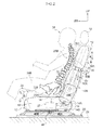
- FIG. 1 principal portions of the seat relating to the present exemplary: embodiment are illustrated by a schematic side view, and in Fig. 2 , a state in which the principal portions of the seat relating to the present exemplary embodiment have moved is illustrated by a schematic side view.
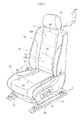
- Fig. 3 the seat relating to the present exemplary embodiment is illustrated by a perspective view, and in Fig. 4 , an enlarged sectional view cut along section line 4-4 of Fig. 3 is illustrated.
- a vehicle seat 10 which serves as the seat of the present exemplary embodiment, is structured to include a seat cushion 12 on which an occupant sits, a seat back 16 that is disposed at a rear end portion side of the seat cushion 12 and can be inclined in the longitudinal direction by a reclining mechanism 14 (see Fig. 1 ), and a head rest 18 that is provided at an upper end portion of the seat back 16 to be vertically adjustable and supports the head of the occupant.
- the vehicle seat 10 is mounted to a vehicle cabin floor portion 21 via a seat track (seat adjuster) 20. Therefore, the vehicle seat 10 is movable in the vehicle longitudinal direction.
- a reclining turning axis 14A of the reclining mechanism 14 of the vehicle seat 10 is disposed with a seat lateral direction (a direction orthogonal to the surface of the paper of Fig. 1 ) being the axial direction.
- the seat back 16 turns to forward in the vehicle (the direction of arrow A in Fig. 2 ) or rearward in the vehicle (the direction of arrow B in Fig. 2 ) with the reclining turning axis 14A as the axis of turning.
- a pelvis detection sensor 24 is disposed inside a seating portion 22 that constitutes a seat cushion seating surface of the seat cushion 12 on which the occupant sits.
- the pelvis detection sensor 24 serves as a pelvis detection unit for detecting displacement of a pelvis 26A of a seated occupant 26 (see Fig. 1 ).
- This pelvis detection sensor 24 is constituted by a sheet-form pressure sensor.
- the pelvis detection sensor 24 detects loads acting on the seating portion 22 of the seat cushion 12 from the pelvis 26A of the seated occupant 26 sitting on the vehicle seat 10, and may detect a peak position thereof.
- the pelvis detection sensor 24 is electrically connected to a control device 27 that serves as a control unit.
- the control device 27 is provided in the seat cushion 12.
- a chest detection sensor 28 is disposed inside an upper portion 16A of the seat back 16, which constitutes a seat back occupant contact surface 17 at the upward side of the seat back 16.
- the chest detection sensor 28 serves as a chest detection unit for detecting displacement of a chest 26B of the seated occupant 26 (see Fig. 1 ).
- the term chest includes the skeleton of the chest, which is formed as a cage by the thoracic vertebrae, the ribs and the sternum.
- the chest detection sensor 28 may detect a load acting on the upper portion 16A of the seat back 16 from the chest 26B of the seated occupant 26 sitting on the vehicle seat 10. More specifically, it may detect a position 26C of one or more of the left and right shoulder blades of the seated occupant 26. Herein, another position may be detected instead of the shoulder blade position 26C.
- the chest detection sensor 28 is electrically connected to the control device 27.
- a pelvis upper portion detection sensor 30 is disposed inside a lower portion 16B of the seat back 16, which constitutes a seat back occupant contact surface 19 at the downward side of the seat back 16.
- the pelvis upper portion detection sensor 30 serves as a pelvis upper portion detection unit for detecting displacement of a pelvis upper portion 26D of the seated occupant 26 (see Fig. 1 ).
- This pelvis upper portion detection sensor 30 is constituted by a sheet-form pressure sensor.
- the pelvis upper portion detection sensor 30 detects a load acting on the lower portions 16B of the seat back 16 from the pelvis upper portion 26D of the seated occupant 26 sitting on the vehicle seat 10, and may detect a peak position thereof.
- the pelvis upper portion detection sensor 30 is electrically connected to the control device 27.
- the pelvis detection sensor 24 is incorporated in a seat cover 38 that covers a seat pad 36 of the seating portion 22 of the seat cushion 12.
- the seat cover 38 has a two layer structure, of a first layer 3 8A that is structured of leather or the like and structures a design surface, and a second layer 38B that is structured of a foam material or the like.
- the pelvis detection sensor 24 is incorporated in the second layer 38B.
- the pelvis detection sensor 24 may be disposed by being stuck onto an upper face of the second layer 38B or the like.
- the chest detection sensor 28 and the pelvis upper portion detection sensor 30 are similarly disposed in a seat skin 40 of the seat back 16.
- the seating portion 22 of the seat cushion 12 is coupled to a seat cushion frame 42 via a seating portion movement device 46, which serves as a pelvis movement unit.
- a motor 46A that structures a portion of the seating portion movement device 46 is electrically connected to the control device 27.
- left and right guide rails 46B which structure portions of the seating portion movement device 46, are provided along the vehicle longitudinal direction between a floor portion 42A of the seat cushion frame 42 and left and right frames 22A of the seating portion 22.
- the seating portion 22 is made relatively movable forward in the vehicle (in the direction of arrow C in Fig. 2 ) or rearward in the vehicle (in the direction of arrow D in Fig. 2 ) along the guide rails 46B relative to the seat cushion frame 42 and the seat back 16 provided at the rear end portion of the seat cushion frame 42, by the motor 46A of the seating portion movement device 46 turning in predetermined directions on the basis of output signals from the control device 27.
- an upper portion movement device 50 is provided inside the seat back 16.
- the upper portion movement device 50 serves as a seat back upper portion movement unit for moving the upper portion 16A of the seat back 16 in the vertical direction.
- a motor 50A that structures a portion of the upper portion movement device 50 is electrically connected to the control device 27.
- Left and right guide arms 50B that structure portions of the upper portion movement device 50 extend toward the lower portion 16B from the upper portion 16A of the seat back 16. By turning of the motor 50A, the left and right guide arms 50B move upward in the seat (in the direction of arrow E in Fig. 2 ) or downward in the seat (in the direction of arrow F in Fig. 2 ).
- the upper portion 16A of the seat back 16 to which the guide arms 50B are attached is made relatively movable upward in the seat (the direction of arrow E in Fig. 2 ) or downward in the seat (the direction of arrow F in Fig. 2 ) relative to the lower portion 16B, by the motor 50A turning in predetermined directions on the basis of output signals from the control device 27.
- the seat back 16 serves as a pelvis upper portion support portion and the reclining mechanism 14 serves as a pelvis upper portion support portion adjustment device.
- a thigh portion 26E of the seated occupant 26 is supported from below by a front portion 22B of the seating portion 22. Therefore, the seated occupant 26 is supported at four locations-the portion of the seating portion 22 at which the pelvis detection sensor 24 is disposed and the front portion 22B thereof, and a portion of the seat back 16 at which the chest detection sensor 28 is disposed and a portion thereof at which the pelvis upper portion detection sensor 30 is disposed.
- the control device 27 detects and memorizes an initial peak position P1 (not illustrated) of a load peak position P.
- the control device 27 detects the position 26C of one or both of the left and right shoulder blades C and memorizes the same as an initial position S1 (not illustrated).
- the load peak position P of the pelvis 26A is a position of a hipbone joint.
- the control device 27 detects and memorizes an initial position T1 (not illustrated) of a load peak position T.
- the pelvis 26A dislocates forward in the vehicle (the direction of arrow M in Fig. 1 ) and the chest 26B dislocates downward in the vehicle (the direction of arrow N in Fig. 1 ) with curving of the spine.
- the control device 27 detects a peak position after displacement P2 (not illustrated) of the load peak position P and compares it with the initial peak position P1 detected in advance.
- the control device 27 causes the seating portion 22 of the seat cushion 12 to move forward in the vehicle or rearward in the vehicle to eliminate this dislocation.
- the seating portion 22 of the seat cushion 12 moves forward in the vehicle (the direction of arrow C in Fig. 2 ) or rearward in the vehicle (the direction of arrow D in Fig. 2 ) relative to the seat cushion frame 42, along the guide rails 46B of the seating portion movement device 46 between a forward position shown by two-dot chain lines in Fig. 2 and a rear position shown by three-dot chain lines, by turning the motor 46A of the seating portion movement device 46 in a predetermined direction with output signals from the control device 27, and eliminates the dislocation between the initial peak position P1 and the peak position after displacement P2 of the load peak position P.
- the seating portion 22 of the seat cushion 12 moves rearward in the vehicle (the direction of arrow D in Fig. 2 ).
- the control device 27 detects a position after displacement S2 (not illustrated) of the shoulder blade position 26C and compares it with the initial position S1 detected in advance.
- the control device 27 causes the upper portion 16A of the seat back 16 to move upward in the vehicle or downward in the vehicle to eliminate this dislocation.
- the upper portion 16A of the seat back 16 moves the upper portion 16A of the seat back 16 upward in the vehicle (the direction of arrow E in Fig. 2 ) or downward in the vehicle (the direction of arrow F in Fig. 2 ) relative to the lower portion 16B, via the guide arms 50B of the upper portion movement device 50 between a downward position shown in Fig. 1 and an upward position shown in Fig. 2 , by turning the motor 50A of the upper portion movement device 50 in a predetermined direction with output signals from the control device 27, and eliminates the dislocation between the initial position S1 and the position after displacement S2 of the shoulder blade position 26C.
- looseness of the seated posture of the seated occupant 26 in the entirety of the body may be reduced. Therefore, even in driving over long periods, if the posture of the seated occupant 26 is formed with the backbone in an S-curve, which is the ideal shape, in an initial state of sitting on the vehicle seat 10, for example, a seated initial state, this posture may be maintained, and tiredness, back pain and the like that are produced by the posture being loose may be suppressed.
- the control device 27 detects a peak position after displacement T2 (not illustrated) of the load peak position T, and compares it with the initial peak position T1 detected in advance.
- the control device 27 causes the seat back 16 to tilt forward in the vehicle (in the direction of arrow A in Fig. 2 ) or rearward in the vehicle (in the direction of arrow B in Fig. 2 ) to eliminate this dislocation.
- the seat back 16 causes the seat back 16 to tilt forward in the vehicle (the direction of arrow A in Fig. 2 ) or rearward in the vehicle (the direction of arrow B in Fig. 2 ) with the reclining turning axis 14A as the turning axis, by turning the motor 14B of the reclining mechanism 14 in a predetermined direction with output signals from the control device 27.
- the seat back 16 tilts to rearward in the vehicle (the direction of arrow B in Fig. 2 ). Further, if the displacement of the pelvis upper portion 26D of the seated occupant 26 is a displacement to downward, the seat back 16 tilts to forward in the vehicle (the direction of arrow A in Fig. 2 ). As a result, looseness of the seated posture of the seated occupant 26 in the entirety of the body may be reduced.
- a second exemplary embodiment of the seat of the present invention is described in accordance with Fig. 5 and Fig. 6 .
- members the same as in the first exemplary embodiment are assigned the same reference numerals and are not described.
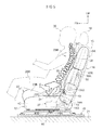
- Fig. 5 principal portions of the seat relating to the present exemplary embodiment are illustrated by a schematic side view, and in Fig. 6 , a portion of the seat relating to the present exemplary embodiment is illustrated by a perspective view.
- an S-spring 70 which serves as the pelvis upper portion support portion, is disposed at a region of a lower portion of the seat back 16 of the vehicle seat 10 that supports the pelvis upper portion 26D of the seated occupant 26 from rearward in the vehicle.
- Each of two end portions 70A of the S-spring 70 are fixed to moving bodies 72A of a spring-moving device 72, which serves as the pelvis upper portion support portion adjustment device.
- the moving bodies 72A are coupled to motors 72B via gears 72C.
- the motors 72B are electrically connected to the control device 27 (see Fig. 5 ).
- the moving bodies 72A move upward in the vehicle (in the direction of arrow G in Fig. 6 ) or downward in the vehicle (in the direction of arrow H in Fig. 6 ) along guide holes 72D that are formed in seat back frames 16C.
- the control device 27 causes the S-spring 70 to move upward in the vehicle (the direction of arrow G in Fig. 6 ) or downward in the vehicle (the direction of arrow H in Fig. 6 ) to eliminate this dislocation.
- the S-spring 70 causes the S-spring 70 to move upward in the vehicle (the direction of arrow G in Fig. 6 ) or downward in the vehicle (the direction of arrow H in Fig. 6 ) by moving the moving bodies 72A along the guide holes 72D, by turning the motors 72B of the spring-moving device 72 in predetermined directions with output signals from the control device 27.
- the S-spring 70 moves to upward in the vehicle (the direction of arrow G in Fig. 6 ) and the pelvis upper portion 26D is supported by the S-spring 70. Further, if the displacement of the pelvis upper portion 26D of the seated occupant 26 is a displacement to downward, the S-spring 70 moves to downward in the vehicle (the direction of arrow H in Fig. 6 ) and the pelvis upper portion 26D is supported by the S-spring 70. As a result, looseness of the seated posture of the seated occupant 26 in the entirety of the body may be reduced.
- the seat back 16 or the S-spring 70 serving as the pelvis upper portion support portion is operated by the control device 27 after the seating portion movement device 46 and the upper portion movement device 50 are operated, looseness of the seated posture of the seated occupant 26 in the entirety of the body may be reduced by the seating portion movement device 46, the upper portion movement device 50 and the pelvis upper portion support portion (the seat back 16 or the S-spring 70) being operated by the control device 27 simultaneously or in a predetermined order.
- the seat cover has a two-layer structure, but a structure in which the seat cover has a single-layer structure, and each sensor of the pelvis detection sensor and the like is disposed between the seat cover and a seat pad, and other structures, in which the seat cover has a three-layer structure or the like, are possible.
- the seat of the present invention is applied to a vehicle seat, but the seat of the present invention is also applicable to seats other than for vehicles.
Landscapes
- Engineering & Computer Science (AREA)
- Aviation & Aerospace Engineering (AREA)
- Transportation (AREA)
- Mechanical Engineering (AREA)
- Seats For Vehicles (AREA)
- Chair Legs, Seat Parts, And Backrests (AREA)
- Acyclic And Carbocyclic Compounds In Medicinal Compositions (AREA)
Abstract
Description
- The present invention relates to a seat, and particularly relates to a seat equipped with a seat cushion and a seat back.
- Heretofore, a seat has been known that is equipped with a seat cushion and a seat back and is capable of adjusting a seated posture of a seated person. For example, in the car seat recited in Patent Reference 1, a seating portion of the car seat includes a seating portion reinforcement frame that supports a suspension grid, and an oscillation unit that generates oscillatory movements in the seating portion. This produces an alternating upward massage effect at the lower side of the thighs and small movements of the lower portion of the spine, at the same time as moving the pelvis rearward to a correct position. Further, a seat recited in Patent Reference 2 is equipped with a lumbar support device that supports the lumbar region of a seat occupant, a pelvis support device that supports the pelvis region, a detection unit that detects turning of the pelvis, and a control unit, and maintains an optimum seated posture.
- Patent Reference 1: Japanese Patent Application Laid-Open (JP-A) No.
2001-353039 - Patent Reference 2: Japanese Utility Model Application Laid-Open (JP-U) No.
H3-19344 - However, with the above-described related art technologies, after sitting on the seat for a long period, a seated person may have a seated posture with great looseness in the entirety of the body. That is, the pelvis region may be displaced and the upper body supported by the seat back may also be displaced.
- In consideration of the circumstances described above, an object of the present invention is to provide a seat that reduces looseness of a seated posture in the entirety of the body.
- A seat relating to a first aspect of the present invention includes: a pelvis detection unit, which is provided at a seat cushion, for detecting a longitudinal direction displacement of a pelvis of a seated occupant relative to a seating surface of the seat cushion; a chest detection unit, which is provided at a seat back, for detecting a vertical direction displacement of a chest of the seated occupant relative to an occupant contact surface of the seat back; a pelvis movement unit that causes a position of the pelvis of the seated occupant to move in the longitudinal direction; a chest movement unit that causes a position of the chest of the seated occupant to move in the vertical direction; and a control unit for causing the pelvis movement unit to operate on the basis of a detection result of the pelvis detection unit and causing the position of the pelvis of the seated occupant to move in a direction to return to a position before displacement, and causing the chest movement unit to operate on the basis of a detection result of the chest detection unit and causing the position of the chest of the seated occupant to move in a direction to return to a position before displacement.
- Thus, on the basis of a longitudinal direction displacement of the pelvis of the seated occupant relative to the seating surface of the seat cushion, which the pelvis detection unit provided at the seat cushion detects, the control unit causes the pelvis movement portion to operate and it moves the position of the pelvis of the seated occupant in a direction to return to the position before displacement. In addition, on the basis of a vertical direction displacement of the chest of the seated occupant relative to the occupant contact surface of the seat back, which the chest detection unit provided at the seat back detects, the control unit causes the chest movement portion to move and it moves the position of the chest of the seated occupant in a direction to return to the position before displacement. Therefore, because the position of the pelvis and the position of the chest of the seated occupant both move in directions to return to positions before displacement, looseness of the seated posture in the entirety of the body may be reduced. Herein, when returning the position of the pelvis or the position of the chest of the seated occupant to the position before displacement, the respective position is moved relative to, for example, a centre of turning of the seat back to eliminate the displacement (dislocation).
- A seat relating to a second aspect of the present invention is the seat relating to the first aspect of the present invention in which the pelvis movement unit is a seating portion movement unit for moving a seating portion of the seat cushion in the longitudinal direction, and the chest movement portion is a seat back upper portion movement portion for moving an upper portion of the seat back in the vertical direction.
- Thus, on the basis of a displacement of the pelvis of the seated occupant, which the pelvis detection unit provided at the seat cushion detects, the control unit causes the seating portion of the seat cushion to be moved in the longitudinal direction by the seating portion movement unit of the seat back and it moves the position of the pelvis of the seated occupant in a direction to return to the position before displacement. In addition, on the basis of a displacement of the chest of the seated occupant, which the chest detection unit provided at the seat back detects, the control unit causes the upper portion of the seat back to be moved in the vertical direction by the upper portion movement unit and it moves the position of the chest of the seated occupant in a direction to return to the position before displacement. Therefore, because the position of the pelvis and the position of the chest of the seated occupant both return toward positions before displacement, looseness of the seated posture in the entirety of the body may be reduced.
- A seat relating to a third aspect of the present invention is the seat relating to the first aspect or the second aspect of the present invention, including a pelvis upper portion detection unit, which is provided at the seat back, for detecting a vertical direction displacement of an upper portion of the pelvis of the seated occupant relative to the occupant contact surface of the seat back; a pelvis upper portion support portion, which is provided at the seat back, that supports the pelvis upper portion of the seated occupant; and a pelvis upper portion support portion adjustment device that changes a position of the pelvis upper portion support portion and causes a position of the pelvis upper portion to move, wherein the control unit adjusts the position of the pelvis upper portion support portion with the pelvis upper portion support portion adjustment device on the basis of a detection result of the pelvis upper portion detection unit and causes the position of the pelvis upper portion of the seated occupant to move in a direction to return to a position before displacement.
- Thus, on the basis of a detection result from the pelvis upper portion detection unit that detects a vertical direction displacement of the upper portion of the pelvis of the seated occupant relative to the occupant contact surface of the seat back, the position of the pelvis upper portion support portion, which is provided at the seat back and supports the pelvis upper portion of the seated occupant, is adjusted by the pelvis upper portion support portion adjustment device, and the position of the pelvis upper portion of the seated occupant moves in a direction to return to the position before displacement. Therefore looseness of the seated posture in the entirety of the body may be reduced.
- A seat relating to a fourth aspect of the present invention is the seat relating to the third aspect of the present invention in which the control unit adjusts the position of the pelvis upper portion support portion with the pelvis upper portion support portion adjustment device on the basis of the detection result of the pelvis upper portion detection unit and causes the position of the pelvis upper portion of the seated occupant to move in the direction to return to the position before displacement after moving the position of the pelvis of the seated occupant with the pelvis movement unit and moving the position of the chest of the seated occupant with the chest movement unit.
- Thus, after the position of the pelvis of the seated occupant is moved by the pelvis movement unit and the position of the chest of the seated occupant is moved by the chest movement unit, on the basis of a detection result from the pelvis upper portion detection unit, the position of the pelvis upper portion support portion is adjusted by the pelvis upper portion support portion adjustment device, and the position of the pelvis upper portion of the seated occupant moves in a direction to return to the position before displacement. Therefore, looseness of the seated posture in the entirety of the body may be reduced.
- A seat relating to a fifth aspect of the present invention is the seat relating to the third aspect or the fourth aspect of the present invention in which the pelvis upper portion support portion is the seat back, and the control unit tilts the seat back rearward with the pelvis upper portion support portion adjustment device if a displacement of the pelvis upper portion of the seated occupant that is detected by the pelvis upper portion detection unit is a displacement upward, and tilts the seat back forward with the pelvis upper portion support portion adjustment device if a displacement of the pelvis upper portion of the seated occupant that is detected by the pelvis upper portion detection unit is a displacement downward.
- Thus, when the position of the pelvis upper portion of the seated occupant detected by the pelvis upper portion detection unit is displaced upward, the control unit tilts the seat back rearward with the pelvis upper portion support portion adjustment device. In addition, when the position of the pelvis upper portion of the seated occupant detected by the pelvis upper portion detection unit is displaced downward, the control unit tilts the seat back forward with the pelvis upper portion support portion adjustment device. Therefore, the position of the pelvis upper portion of the seated occupant may be returned to the position before displacement by reclining the seat back in the longitudinal direction. Therefore, looseness of the seated posture in the entirety of the body may be reduced.
- A seat relating to a sixth aspect of the present invention is the seat relating to the third aspect or the fourth aspect of the present invention in which the pelvis upper portion support portion is a spring that is disposed at the seat back and supports the pelvis upper portion, and the control unit moves the spring upward in the seat back with the pelvis upper portion support portion adjustment device if a displacement of the pelvis upper portion of the seated occupant that is detected by the pelvis upper portion detection unit is a displacement to upward, and moves the spring downward in the seat back with the pelvis upper portion support portion adjustment device if a displacement of the pelvis upper portion of the seated occupant that is detected by the pelvis upper portion detection unit is a displacement to downward.
- Thus, when the position of the pelvis upper portion of the seated occupant detected by the pelvis upper portion detection unit is displaced upward, the control unit moves the spring that is provided in the seat back and that supports the pelvis upper portion upward with the pelvis upper portion support portion adjustment device. In addition, when the position of the pelvis upper portion of the seated occupant detected by the pelvis upper portion detection unit is displaced downward, the control unit moves the spring downward with the pelvis upper portion support portion adjustment device. Therefore, the angle of the pelvis is continuously maintained by the spring abutting against and supporting the pelvis upper portion, and looseness of the seated posture may be reduced. Therefore, looseness of the seated posture in the entirety of the body may be reduced.
- According to the present invention, looseness of the seated posture in the entirety of the body may be reduced.
-
-
Fig. 1 is a schematic side view illustrating principal portions of a seat relating to a first exemplary embodiment of the present invention. -
Fig. 2 is a schematic side view illustrating movements of the principal portions of the seat relating to the first exemplary embodiment of the present invention. -
Fig. 3 is a perspective view, seen from obliquely forward, illustrating the seat relating to the first exemplary embodiment of the present invention. -
Fig. 4 is an enlarged sectional view cut along section line 4-4 ofFig. 3 . -
Fig. 5 is a schematic side view illustrating principal portions of a seat relating to a second exemplary embodiment of the present invention. -
Fig. 6 is a perspective view, seen from obliquely forward, illustrating a portion of the seat relating to the second exemplary embodiment of the present invention. - A first exemplary embodiment of a seat of the present invention is described in accordance with
Fig. 1 to Fig. 4 . Herein, an arrow FR that is shown where suitable in these drawings indicates a vehicle forward side, and an arrow UP indicates a vehicle upward side. - In
Fig. 1 , principal portions of the seat relating to the present exemplary: embodiment are illustrated by a schematic side view, and inFig. 2 , a state in which the principal portions of the seat relating to the present exemplary embodiment have moved is illustrated by a schematic side view. InFig. 3 , the seat relating to the present exemplary embodiment is illustrated by a perspective view, and inFig. 4 , an enlarged sectional view cut along section line 4-4 ofFig. 3 is illustrated. - As illustrated in
Fig. 3 , avehicle seat 10, which serves as the seat of the present exemplary embodiment, is structured to include aseat cushion 12 on which an occupant sits, aseat back 16 that is disposed at a rear end portion side of theseat cushion 12 and can be inclined in the longitudinal direction by a reclining mechanism 14 (seeFig. 1 ), and ahead rest 18 that is provided at an upper end portion of theseat back 16 to be vertically adjustable and supports the head of the occupant. - Herein, the
vehicle seat 10 is mounted to a vehiclecabin floor portion 21 via a seat track (seat adjuster) 20. Therefore, thevehicle seat 10 is movable in the vehicle longitudinal direction. - As illustrated in
Fig. 1 , a recliningturning axis 14A of the recliningmechanism 14 of thevehicle seat 10 is disposed with a seat lateral direction (a direction orthogonal to the surface of the paper ofFig. 1 ) being the axial direction. At a time of reclining, by turning of amotor 14B that constitutes the recliningmechanism 14, theseat back 16 turns to forward in the vehicle (the direction of arrow A inFig. 2 ) or rearward in the vehicle (the direction of arrow B inFig. 2 ) with the recliningturning axis 14A as the axis of turning. - As illustrated in
Fig. 3 , apelvis detection sensor 24 is disposed inside aseating portion 22 that constitutes a seat cushion seating surface of theseat cushion 12 on which the occupant sits. Thepelvis detection sensor 24 serves as a pelvis detection unit for detecting displacement of apelvis 26A of a seated occupant 26 (seeFig. 1 ). Thispelvis detection sensor 24 is constituted by a sheet-form pressure sensor. - As illustrated in
Fig. 1 , thepelvis detection sensor 24 detects loads acting on theseating portion 22 of theseat cushion 12 from thepelvis 26A of theseated occupant 26 sitting on thevehicle seat 10, and may detect a peak position thereof. Thepelvis detection sensor 24 is electrically connected to acontrol device 27 that serves as a control unit. Thecontrol device 27 is provided in theseat cushion 12. - As illustrated in
Fig. 3 , achest detection sensor 28 is disposed inside anupper portion 16A of the seat back 16, which constitutes a seat backoccupant contact surface 17 at the upward side of the seat back 16. Thechest detection sensor 28 serves as a chest detection unit for detecting displacement of achest 26B of the seated occupant 26 (seeFig. 1 ). Herein, the term chest includes the skeleton of the chest, which is formed as a cage by the thoracic vertebrae, the ribs and the sternum. - As illustrated in
Fig. 1 , thechest detection sensor 28 may detect a load acting on theupper portion 16A of the seat back 16 from thechest 26B of the seatedoccupant 26 sitting on thevehicle seat 10. More specifically, it may detect aposition 26C of one or more of the left and right shoulder blades of the seatedoccupant 26. Herein, another position may be detected instead of theshoulder blade position 26C. Thechest detection sensor 28 is electrically connected to thecontrol device 27. - As illustrated in
Fig. 3 , a pelvis upperportion detection sensor 30 is disposed inside alower portion 16B of the seat back 16, which constitutes a seat backoccupant contact surface 19 at the downward side of the seat back 16. The pelvis upperportion detection sensor 30 serves as a pelvis upper portion detection unit for detecting displacement of a pelvisupper portion 26D of the seated occupant 26 (seeFig. 1 ). This pelvis upperportion detection sensor 30 is constituted by a sheet-form pressure sensor. - As illustrated in
Fig. 1 , the pelvis upperportion detection sensor 30 detects a load acting on thelower portions 16B of the seat back 16 from the pelvisupper portion 26D of the seatedoccupant 26 sitting on thevehicle seat 10, and may detect a peak position thereof. The pelvis upperportion detection sensor 30 is electrically connected to thecontrol device 27. - As illustrated in
Fig. 4 , thepelvis detection sensor 24 is incorporated in aseat cover 38 that covers aseat pad 36 of theseating portion 22 of theseat cushion 12. Describing it more specifically, theseat cover 38 has a two layer structure, of a first layer 3 8A that is structured of leather or the like and structures a design surface, and asecond layer 38B that is structured of a foam material or the like. Thepelvis detection sensor 24 is incorporated in thesecond layer 38B. Herein, thepelvis detection sensor 24 may be disposed by being stuck onto an upper face of thesecond layer 38B or the like. - Although not illustrated in the drawings, the
chest detection sensor 28 and the pelvis upperportion detection sensor 30 are similarly disposed in aseat skin 40 of the seat back 16. - As illustrated in
Fig. 1 , the seatingportion 22 of theseat cushion 12 is coupled to aseat cushion frame 42 via a seatingportion movement device 46, which serves as a pelvis movement unit. Amotor 46A that structures a portion of the seatingportion movement device 46 is electrically connected to thecontrol device 27. - As illustrated in
Fig. 4 , left and right guide rails 46B, which structure portions of the seatingportion movement device 46, are provided along the vehicle longitudinal direction between afloor portion 42A of theseat cushion frame 42 and left andright frames 22A of theseating portion 22. - Thus, the seating
portion 22 is made relatively movable forward in the vehicle (in the direction of arrow C inFig. 2 ) or rearward in the vehicle (in the direction of arrow D inFig. 2 ) along the guide rails 46B relative to theseat cushion frame 42 and the seat back 16 provided at the rear end portion of theseat cushion frame 42, by themotor 46A of the seatingportion movement device 46 turning in predetermined directions on the basis of output signals from thecontrol device 27. - As illustrated in
Fig. 1 an upperportion movement device 50 is provided inside the seat back 16. The upperportion movement device 50 serves as a seat back upper portion movement unit for moving theupper portion 16A of the seat back 16 in the vertical direction. Amotor 50A that structures a portion of the upperportion movement device 50 is electrically connected to thecontrol device 27. Left and right guidearms 50B that structure portions of the upperportion movement device 50 extend toward thelower portion 16B from theupper portion 16A of the seat back 16. By turning of themotor 50A, the left and right guidearms 50B move upward in the seat (in the direction of arrow E inFig. 2 ) or downward in the seat (in the direction of arrow F inFig. 2 ). - Thus, the
upper portion 16A of the seat back 16 to which theguide arms 50B are attached is made relatively movable upward in the seat (the direction of arrow E inFig. 2 ) or downward in the seat (the direction of arrow F inFig. 2 ) relative to thelower portion 16B, by themotor 50A turning in predetermined directions on the basis of output signals from thecontrol device 27. - Further, in the present exemplary embodiment, the seat back 16 serves as a pelvis upper portion support portion and the
reclining mechanism 14 serves as a pelvis upper portion support portion adjustment device. - Herein, as illustrated in
Fig. 1 , athigh portion 26E of the seatedoccupant 26 is supported from below by afront portion 22B of theseating portion 22. Therefore, the seatedoccupant 26 is supported at four locations-the portion of theseating portion 22 at which thepelvis detection sensor 24 is disposed and thefront portion 22B thereof, and a portion of the seat back 16 at which thechest detection sensor 28 is disposed and a portion thereof at which the pelvis upperportion detection sensor 30 is disposed. - Next, operations and effects of the above exemplary embodiment are described.
- In the present exemplary embodiment, when the seated
occupant 26 is seated on thevehicle seat 10, from a load distribution of thepelvis 26A of the seatedoccupant 26 that thepelvis detection sensor 24 provided at theseating portion 22 of theseat cushion 12 of thevehicle seat 10 detects, thecontrol device 27 detects and memorizes an initial peak position P1 (not illustrated) of a load peak position P. In addition, from a load distribution of thechest 26B of the seatedoccupant 26 that thechest detection sensor 28 provided at the upper portion of the seat back 16 of thevehicle seat 10 detects, thecontrol device 27 detects theposition 26C of one or both of the left and right shoulder blades C and memorizes the same as an initial position S1 (not illustrated). Herein, the load peak position P of thepelvis 26A is a position of a hipbone joint. - Furthermore, in the present exemplary embodiment, when the seated
occupant 26 is seated on thevehicle seat 10, from a load distribution of the pelvisupper portion 26D of the seatedoccupant 26 that the pelvis upperportion detection sensor 30 provided at the lower portion of the seat back 16 of thevehicle seat 10 detects, thecontrol device 27 detects and memorizes an initial position T1 (not illustrated) of a load peak position T. - Furthermore, when the seated
occupant 26 is seated on thevehicle seat 10 for a long period, generally, thepelvis 26A dislocates forward in the vehicle (the direction of arrow M inFig. 1 ) and thechest 26B dislocates downward in the vehicle (the direction of arrow N inFig. 1 ) with curving of the spine. - Accordingly, at a predetermined timing, for example, after each passage of a predetermined period, from the load distribution of the
pelvis 26A of the seatedoccupant 26 that thepelvis detection sensor 24 provided at theseating portion 22 of theseat cushion 12 of thevehicle seat 10 detects, thecontrol device 27 detects a peak position after displacement P2 (not illustrated) of the load peak position P and compares it with the initial peak position P1 detected in advance. - Then, if a dislocation between the initial peak position P1 and the peak position after displacement P2 of the load peak position P of the
pelvis 26A of the seatedoccupant 26 is greater than a predetermined value, thecontrol device 27 causes theseating portion 22 of theseat cushion 12 to move forward in the vehicle or rearward in the vehicle to eliminate this dislocation. - Specifically, it moves the
seating portion 22 of theseat cushion 12 forward in the vehicle (the direction of arrow C inFig. 2 ) or rearward in the vehicle (the direction of arrow D inFig. 2 ) relative to theseat cushion frame 42, along the guide rails 46B of the seatingportion movement device 46 between a forward position shown by two-dot chain lines inFig. 2 and a rear position shown by three-dot chain lines, by turning themotor 46A of the seatingportion movement device 46 in a predetermined direction with output signals from thecontrol device 27, and eliminates the dislocation between the initial peak position P1 and the peak position after displacement P2 of the load peak position P. - For example, if the peak position after displacement P2 of the load peak position P has moved forward in the vehicle relative to the initial peak position P1, the seating
portion 22 of theseat cushion 12 moves rearward in the vehicle (the direction of arrow D inFig. 2 ). - Next, from the load distribution of the
chest 26B of the seatedoccupant 26 that thechest detection sensor 28 provided at the upper portion of the seat back 16 of thevehicle seat 10 detects, thecontrol device 27 detects a position after displacement S2 (not illustrated) of theshoulder blade position 26C and compares it with the initial position S1 detected in advance. - Then, if a dislocation between the initial position S1 and the peak position after displacement S2 of the
shoulder blade position 26C of the seatedoccupant 26 is greater than a predetermined value, thecontrol device 27 causes theupper portion 16A of the seat back 16 to move upward in the vehicle or downward in the vehicle to eliminate this dislocation. - Specifically, it moves the
upper portion 16A of the seat back 16 upward in the vehicle (the direction of arrow E inFig. 2 ) or downward in the vehicle (the direction of arrow F inFig. 2 ) relative to thelower portion 16B, via theguide arms 50B of the upperportion movement device 50 between a downward position shown inFig. 1 and an upward position shown inFig. 2 , by turning themotor 50A of the upperportion movement device 50 in a predetermined direction with output signals from thecontrol device 27, and eliminates the dislocation between the initial position S1 and the position after displacement S2 of theshoulder blade position 26C. - For example, if the position after displacement S2 of the
shoulder blade position 26C has moved downward relative to the initial position S1, theupper portion 16A of the seat back 16 moves upward in the vehicle relative to thelower portion 16B (the direction of arrow E inFig. 2 ). - As a result, both the position of the
pelvis 26A of the seatedoccupant 26 and theposition 26C of one or more of the left and right shoulder blades, which serves as a position of thechest 26B, return to positions before displacement (initial positions). Thus, looseness of the seated posture of the seatedoccupant 26 in the entirety of the body may be reduced. Therefore, even in driving over long periods, if the posture of the seatedoccupant 26 is formed with the backbone in an S-curve, which is the ideal shape, in an initial state of sitting on thevehicle seat 10, for example, a seated initial state, this posture may be maintained, and tiredness, back pain and the like that are produced by the posture being loose may be suppressed. - Moreover, in the present exemplary embodiment, after the seating
portion movement device 46 and the upperportion movement device 50 are operated, from the load distribution of the pelvisupper portion 26D of the seatedoccupant 26 that the pelvis upperportion detection sensor 30 provided at the lower portion of the seat back 16 of thevehicle seat 10 detects, thecontrol device 27 detects a peak position after displacement T2 (not illustrated) of the load peak position T, and compares it with the initial peak position T1 detected in advance. - Then, if a dislocation between the initial peak position T1 and the peak position after displacement T2 of the load distribution of the pelvis
upper portion 26D of the seatedoccupant 26 is greater than a predetermined value, thecontrol device 27 causes the seat back 16 to tilt forward in the vehicle (in the direction of arrow A inFig. 2 ) or rearward in the vehicle (in the direction of arrow B inFig. 2 ) to eliminate this dislocation. - Specifically, it causes the seat back 16 to tilt forward in the vehicle (the direction of arrow A in
Fig. 2 ) or rearward in the vehicle (the direction of arrow B inFig. 2 ) with thereclining turning axis 14A as the turning axis, by turning themotor 14B of thereclining mechanism 14 in a predetermined direction with output signals from thecontrol device 27. - For example, if the displacement of the pelvis
upper portion 26D of the seatedoccupant 26 is a displacement to upward, the seat back 16 tilts to rearward in the vehicle (the direction of arrow B inFig. 2 ). Further, if the displacement of the pelvisupper portion 26D of the seatedoccupant 26 is a displacement to downward, the seat back 16 tilts to forward in the vehicle (the direction of arrow A inFig. 2 ). As a result, looseness of the seated posture of the seatedoccupant 26 in the entirety of the body may be reduced. - Herein, if a positional dislocation of the pelvis
upper portion 26D of the seatedoccupant 26 is returned by adjustment of the tilt angle of the seat back 16, the position of thechest 26B of the seatedoccupant 26 is displaced a little by the movement of the seat back 16. In order to suppress this displacement, a structure is possible that employs an articulated mechanism in which a vertical direction middle portion of the seat back 16 is tiltable in the vehicle longitudinal direction and, by adjustment of this articulated mechanism, prevents re-dislocation in association with correction of a a dislocation amount of the pelvisupper portion 26D. - Next, a second exemplary embodiment of the seat of the present invention is described in accordance with
Fig. 5 andFig. 6 . Herein, members the same as in the first exemplary embodiment are assigned the same reference numerals and are not described. - In
Fig. 5 , principal portions of the seat relating to the present exemplary embodiment are illustrated by a schematic side view, and inFig. 6 , a portion of the seat relating to the present exemplary embodiment is illustrated by a perspective view. - As illustrated in
Fig. 5 andFig. 6 , in the present exemplary embodiment, an S-spring 70, which serves as the pelvis upper portion support portion, is disposed at a region of a lower portion of the seat back 16 of thevehicle seat 10 that supports the pelvisupper portion 26D of the seatedoccupant 26 from rearward in the vehicle. Each of twoend portions 70A of the S-spring 70 are fixed to movingbodies 72A of a spring-movingdevice 72, which serves as the pelvis upper portion support portion adjustment device. The movingbodies 72A are coupled tomotors 72B viagears 72C. Themotors 72B are electrically connected to the control device 27 (seeFig. 5 ). By thecontrol device 27 turning themotors 72B in predetermined directions, the movingbodies 72A move upward in the vehicle (in the direction of arrow G inFig. 6 ) or downward in the vehicle (in the direction of arrow H inFig. 6 ) alongguide holes 72D that are formed in seat back frames 16C. - Thus, in the present exemplary embodiment, similarly to the first exemplary embodiment, after the seating
portion movement device 46 and the upperportion movement device 50 are operated, if a dislocation between the initial peak position T1 and the peak position after displacement T2 of the load distribution of the pelvisupper portion 26D of the seatedoccupant 26 is greater than a predetermined value, thecontrol device 27 causes the S-spring 70 to move upward in the vehicle (the direction of arrow G inFig. 6 ) or downward in the vehicle (the direction of arrow H inFig. 6 ) to eliminate this dislocation. - Specifically, it causes the S-
spring 70 to move upward in the vehicle (the direction of arrow G inFig. 6 ) or downward in the vehicle (the direction of arrow H inFig. 6 ) by moving the movingbodies 72A along the guide holes 72D, by turning themotors 72B of the spring-movingdevice 72 in predetermined directions with output signals from thecontrol device 27. - For example, if the displacement of the pelvis
upper portion 26D of the seatedoccupant 26 is a displacement to upward, the S-spring 70 moves to upward in the vehicle (the direction of arrow G inFig. 6 ) and the pelvisupper portion 26D is supported by the S-spring 70. Further, if the displacement of the pelvisupper portion 26D of the seatedoccupant 26 is a displacement to downward, the S-spring 70 moves to downward in the vehicle (the direction of arrow H inFig. 6 ) and the pelvisupper portion 26D is supported by the S-spring 70. As a result, looseness of the seated posture of the seatedoccupant 26 in the entirety of the body may be reduced. - In the above, detailed descriptions of particular embodiments of the present invention have been described, but the present invention is not to be limited by the above exemplary embodiments and it will be apparent to practitioners skilled in the art that numerous other embodiments are possible within the technical scope of the present invention. For example, although the seat back 16 or the S-
spring 70 serving as the pelvis upper portion support portion is operated by thecontrol device 27 after the seatingportion movement device 46 and the upperportion movement device 50 are operated, looseness of the seated posture of the seatedoccupant 26 in the entirety of the body may be reduced by the seatingportion movement device 46, the upperportion movement device 50 and the pelvis upper portion support portion (the seat back 16 or the S-spring 70) being operated by thecontrol device 27 simultaneously or in a predetermined order. - Further, in the above exemplary embodiments, the seat cover has a two-layer structure, but a structure in which the seat cover has a single-layer structure, and each sensor of the pelvis detection sensor and the like is disposed between the seat cover and a seat pad, and other structures, in which the seat cover has a three-layer structure or the like, are possible.
- Further, in the above exemplary embodiments the seat of the present invention is applied to a vehicle seat, but the seat of the present invention is also applicable to seats other than for vehicles.
Claims (6)
- A seat comprising:a pelvis detection unit, which is provided at a seat cushion, for detecting a longitudinal direction displacement of a pelvis of a seated occupant relative to a seating surface of the seat cushion;a chest detection unit, which is provided at a seat back, for detecting a vertical direction displacement of a chest of the seated occupant relative to an occupant contact surface of the seat back;a pelvis movement unit that causes a position of the pelvis of the seated occupant to move in the longitudinal direction;a chest movement unit that causes a position of the chest of the seated occupant to move in the vertical direction; anda control unit for
causing the pelvis movement unit to operate on the basis of a detection result of the pelvis detection unit and causing the position of the pelvis of the seated occupant to move in a direction to return to a position before displacement, and
causing the chest movement unit to operate on the basis of a detection result of the chest detection unit and causing the position of the chest of the seated occupant to move in a direction to return to a position before displacement. - The seat according to claim 1, wherein the pelvis movement unit is a seating portion movement unit for moving a seating portion of the seat cushion in the longitudinal direction, and the chest movement unit is a seat back upper portion movement unit for moving an upper portion of the seat back in the vertical direction.
- The seat according to claim 1 or claim 2, further comprising:a pelvis upper portion detection unit, which is provided at the seat back, for detecting a vertical direction displacement of an upper portion of the pelvis of the seated occupant relative to the occupant contact surface of the seat back;a pelvis upper portion support portion, which is provided at the seat back, that supports the pelvis upper portion of the seated occupant; anda pelvis upper portion support portion adjustment device that changes a position of the pelvis upper portion support portion and causes a position of the pelvis upper portion to move,wherein the control unit adjusts the position of the pelvis upper portion support portion with the pelvis upper portion support portion adjustment device on the basis of a detection result of the pelvis upper portion detection unit and causes the position of the pelvis upper portion of the seated occupant to move in a direction to return to a position before displacement.
- The seat according to claim 3, wherein the control unit adjusts the position of the pelvis upper portion support portion with the pelvis upper portion support portion adjustment device on the basis of the detection result of the pelvis upper portion detection unit and causes the position of the pelvis upper portion of the seated occupant to move in the direction to return to the position before displacement after moving the position of the pelvis of the seated occupant with the pelvis movement unit and moving the position of the chest of the seated occupant with the chest movement unit.
- The seat according to claim 3 or claim 4, wherein the pelvis upper portion support portion is the seat back, and the control unit tilts the seat back rearward with the pelvis upper portion support portion adjustment device if a displacement of the pelvis upper portion of the seated occupant that is detected by the pelvis upper portion detection unit is a displacement upward, and tilts the seat back forward with the pelvis upper portion support portion adjustment device if a displacement of the pelvis upper portion of the seated occupant that is detected by the pelvis upper portion detection unit is a displacement downward.
- The seat according to claim 3 or claim 4, wherein the pelvis upper portion support portion is a spring that is disposed at the seat back and supports the pelvis upper portion, and the control unit moves the spring upward in the seat back with the pelvis upper portion support portion adjustment device if a displacement of the pelvis upper portion of the seated occupant that is detected by the pelvis upper portion detection unit is a displacement upward, and moves the spring downward in the seat back with the pelvis upper portion support portion adjustment device if a displacement of the pelvis upper portion of the seated occupant that is detected by the pelvis upper portion detection unit is a displacement downward.
Applications Claiming Priority (2)
| Application Number | Priority Date | Filing Date | Title |
|---|---|---|---|
| JP2008005655A JP4347385B2 (en) | 2008-01-15 | 2008-01-15 | seat |
| PCT/JP2009/050366 WO2009090954A1 (en) | 2008-01-15 | 2009-01-14 | Seat |
Publications (3)
| Publication Number | Publication Date |
|---|---|
| EP2233345A1 true EP2233345A1 (en) | 2010-09-29 |
| EP2233345A4 EP2233345A4 (en) | 2011-05-11 |
| EP2233345B1 EP2233345B1 (en) | 2012-03-21 |
Family
ID=40885343
Family Applications (1)
| Application Number | Title | Priority Date | Filing Date |
|---|---|---|---|
| EP09702110A Not-in-force EP2233345B1 (en) | 2008-01-15 | 2009-01-14 | Seat |
Country Status (7)
| Country | Link |
|---|---|
| US (1) | US8348339B2 (en) |
| EP (1) | EP2233345B1 (en) |
| JP (1) | JP4347385B2 (en) |
| KR (1) | KR101155733B1 (en) |
| CN (1) | CN101909932B (en) |
| AT (1) | ATE550219T1 (en) |
| WO (1) | WO2009090954A1 (en) |
Families Citing this family (39)
| Publication number | Priority date | Publication date | Assignee | Title |
|---|---|---|---|---|
| JP5458710B2 (en) * | 2009-07-14 | 2014-04-02 | 東ソー株式会社 | Pink zirconia sintered body |
| BR112013007306B1 (en) | 2010-10-01 | 2020-08-04 | Nissan Motor., Ltd | VEHICLE SEAT AND METHOD OF ADJUSTING THE RIGIDITY FOR THE SAME |
| US10455945B2 (en) * | 2012-10-23 | 2019-10-29 | Lear Corporation | Thoracic region comfort seating system |
| EP2927048A4 (en) | 2012-11-28 | 2016-01-06 | Ts Tech Co Ltd | VEHICLE SEAT |
| KR101522589B1 (en) * | 2013-03-08 | 2015-05-26 | (주)릴렉스테크 | Massage Chair |
| US9987961B2 (en) * | 2014-06-09 | 2018-06-05 | Lear Corporation | Adjustable seat assembly |
| US10328823B2 (en) | 2014-06-09 | 2019-06-25 | Lear Corporation | Adjustable seat assembly |
| JP6629501B2 (en) * | 2014-08-27 | 2020-01-15 | 株式会社タチエス | Vehicle seat |
| DE102014113869A1 (en) * | 2014-09-24 | 2016-03-24 | Mack Rides Gmbh & Co. Kg | Device for restraining a passenger in a holder of a ride |
| US9884570B2 (en) | 2015-05-19 | 2018-02-06 | Lear Corporation | Adjustable seat assembly |
| US9845026B2 (en) | 2015-05-19 | 2017-12-19 | Lear Corporation | Adjustable seat assembly |
| KR101801840B1 (en) * | 2015-07-14 | 2017-11-28 | 서울대학교병원 | Decompression chair and decompression apparatus for easing lumbar pain |
| US9661928B2 (en) | 2015-09-29 | 2017-05-30 | Lear Corporation | Air bladder assembly for seat bottoms of seat assemblies |
| US9758079B2 (en) * | 2015-10-08 | 2017-09-12 | Lear Corporation | Adjustable seat assembly |
| CN105253042A (en) * | 2015-10-28 | 2016-01-20 | 桂林新艺制冷设备有限责任公司 | Seat with deformation voice prompt function |
| US9827888B2 (en) | 2016-01-04 | 2017-11-28 | Lear Corporation | Seat assemblies with adjustable side bolster actuators |
| US10632866B2 (en) * | 2016-06-03 | 2020-04-28 | Faurecia Automotive Seating, Llc | Movement system for a vehicle seat |
| US10384565B2 (en) | 2016-07-29 | 2019-08-20 | Lear Corporation | Adjustable seat assembly |
| WO2018051579A1 (en) * | 2016-09-13 | 2018-03-22 | 株式会社タチエス | Vehicle seat |
| US10232814B2 (en) * | 2017-01-18 | 2019-03-19 | Toyota Motor Engineering & Manufacturing North America, Inc. | Inflatable vehicle occupant positioning system |
| WO2018151779A1 (en) | 2017-02-17 | 2018-08-23 | Zodiac Seats Us Llc | Passenger seat with comfort layout |
| US10988055B2 (en) * | 2017-03-17 | 2021-04-27 | Safran Seats Usa Llc | Passenger seat with movable backrest portion |
| DE102017206313B4 (en) * | 2017-04-12 | 2023-01-19 | Ford Global Technologies, Llc | Method for seat adjustment of a means of transport |
| CN107089170B (en) * | 2017-04-19 | 2019-09-06 | 京东方科技集团股份有限公司 | Seat system |
| US10384566B2 (en) * | 2017-08-25 | 2019-08-20 | Ford Global Technologies, Llc | Vehicle seat assembly |
| JP6572336B2 (en) * | 2018-02-13 | 2019-09-04 | 本田技研工業株式会社 | Vehicle seat occupant posture adjustment device |
| JP2019156247A (en) * | 2018-03-15 | 2019-09-19 | 本田技研工業株式会社 | Seat device |
| JP6660425B2 (en) * | 2018-07-20 | 2020-03-11 | ミネベアミツミ株式会社 | Attitude control device |
| US10611283B2 (en) * | 2018-09-12 | 2020-04-07 | Rockwell Collins, Inc. | Multi-stage seatback extension system |
| US10717534B2 (en) * | 2018-12-17 | 2020-07-21 | Goodrich Corporation | Extendable split headrest |
| JP2020111252A (en) * | 2019-01-15 | 2020-07-27 | 日本発條株式会社 | Vehicle seat |
| AU2020212655B2 (en) * | 2019-01-25 | 2020-10-15 | Rc Services Australia Pty Ltd | Support cushion |
| AT523112A1 (en) * | 2019-10-16 | 2021-05-15 | Zenzmaier Cornelia | Method for determining the location and position of a person's pelvis |
| US11801776B2 (en) | 2020-12-09 | 2023-10-31 | Ford Global Technologies, Llc | Vehicle seating system |
| JP7728116B2 (en) | 2021-07-30 | 2025-08-22 | 株式会社Subaru | Sheet |
| EP4166386B1 (en) * | 2021-10-14 | 2025-11-12 | Ningbo Geely Automobile Research & Development Co. Ltd. | A vehicle seat and a method for operating a vehicle seat |
| JP7804542B2 (en) * | 2022-06-30 | 2026-01-22 | 株式会社Subaru | Scapula position estimation device and seat |
| US12240360B2 (en) * | 2023-02-09 | 2025-03-04 | GM Global Technology Operations LLC | Vertically height adjustable seatback for a vehicle |
| US20250303932A1 (en) * | 2024-04-02 | 2025-10-02 | Ford Global Technologies, Llc | Extendable seatback |
Family Cites Families (14)
| Publication number | Priority date | Publication date | Assignee | Title |
|---|---|---|---|---|
| BE897046A (en) * | 1983-06-14 | 1983-10-03 | Mevergnies Marcel Neve De | ARMCHAIR FOR VEHICLE, PARTICULARLY AUTOMOTIVE |
| JPH076835Y2 (en) * | 1989-07-05 | 1995-02-22 | 日産自動車株式会社 | Seat |
| JP3006398B2 (en) | 1993-05-05 | 2000-02-07 | インターナショナル・ビジネス・マシーンズ・コーポレイション | Cable assembly |
| JP3019344U (en) | 1995-06-13 | 1995-12-12 | マミヤ・オーピー株式会社 | Combination lure |
| US5836647A (en) * | 1997-05-20 | 1998-11-17 | Turman; Ben | Vehicle seat with shock absorption |
| DE19853156B4 (en) * | 1998-11-18 | 2006-04-13 | Girsberger Holding Ag | Seat |
| FR2808246B1 (en) | 2000-04-27 | 2002-07-19 | Faure Bertrand Equipements Sa | MOTOR VEHICLE SEAT SEAT HAVING A MASSAGE EFFECT |
| US6640653B1 (en) * | 2002-05-30 | 2003-11-04 | Tachi-S Co., Ltd. | Load detection structure for vehicle seat |
| JP2005052433A (en) | 2003-08-05 | 2005-03-03 | Nissan Motor Co Ltd | Vehicle seat device |
| US7152920B2 (en) | 2003-10-21 | 2006-12-26 | Ts Tech Co., Ltd. | Vehicle seat with system for facilitating relieving of fatigue of person sitting on the seat |
| JP2005125846A (en) | 2003-10-21 | 2005-05-19 | T S Tec Kk | Vehicle seat with fatigue relieving function |
| DE102006002919B4 (en) * | 2005-01-24 | 2008-09-04 | Denso Corp., Kariya | Capacitive sensor and occupant detection system |
| JP2006290099A (en) | 2005-04-08 | 2006-10-26 | Nissan Motor Co Ltd | Driving posture adjusting apparatus and method |
| JP2008002838A (en) * | 2006-06-20 | 2008-01-10 | Takata Corp | Vehicle occupant detection system, actuator control system, vehicle |
-
2008
- 2008-01-15 JP JP2008005655A patent/JP4347385B2/en not_active Expired - Fee Related
-
2009
- 2009-01-14 AT AT09702110T patent/ATE550219T1/en active
- 2009-01-14 KR KR1020107017967A patent/KR101155733B1/en not_active Expired - Fee Related
- 2009-01-14 CN CN2009801022857A patent/CN101909932B/en not_active Expired - Fee Related
- 2009-01-14 EP EP09702110A patent/EP2233345B1/en not_active Not-in-force
- 2009-01-14 WO PCT/JP2009/050366 patent/WO2009090954A1/en not_active Ceased
- 2009-01-14 US US12/812,389 patent/US8348339B2/en not_active Expired - Fee Related
Also Published As
| Publication number | Publication date |
|---|---|
| CN101909932B (en) | 2012-07-25 |
| CN101909932A (en) | 2010-12-08 |
| JP4347385B2 (en) | 2009-10-21 |
| WO2009090954A1 (en) | 2009-07-23 |
| KR101155733B1 (en) | 2012-06-12 |
| EP2233345B1 (en) | 2012-03-21 |
| US8348339B2 (en) | 2013-01-08 |
| US20100283299A1 (en) | 2010-11-11 |
| KR20100101176A (en) | 2010-09-16 |
| ATE550219T1 (en) | 2012-04-15 |
| EP2233345A4 (en) | 2011-05-11 |
| JP2009165588A (en) | 2009-07-30 |
Similar Documents
| Publication | Publication Date | Title |
|---|---|---|
| EP2233345B1 (en) | Seat | |
| KR102791546B1 (en) | System for controlling seat of vehicle | |
| US10065535B1 (en) | Seatback lift mechanism for a supine motor vehicle seating assembly | |
| US9981569B2 (en) | Reclinable seat | |
| US10569674B2 (en) | Mechanism for a supine motor vehicle seating assembly | |
| US20170217341A1 (en) | Vehicle seat | |
| US20240300395A1 (en) | Conveyance seat | |
| JP2013163405A (en) | Vehicle seat | |
| US9815391B2 (en) | Vehicle seat with side pieces made of autoreactive framework structures | |
| JP5625811B2 (en) | Standing seat device | |
| JP6059633B2 (en) | Vehicle seat | |
| US20250376086A1 (en) | Vehicle seat | |
| JP6364309B2 (en) | Sheet | |
| US9402480B2 (en) | Adjustable seat assembly | |
| JP5935627B2 (en) | Seat frame | |
| JP2019072244A (en) | Seat cushion | |
| JP6000871B2 (en) | Vehicle seat | |
| JP2009240373A (en) | Seat device | |
| JP2021142867A (en) | Vehicle seat | |
| JP7143573B2 (en) | vehicle seat | |
| JP7712534B2 (en) | Vehicle seats | |
| JP2024005354A (en) | sheet | |
| JP2020083105A (en) | Vehicle seat structure | |
| JP2019031225A (en) | Vehicle seat | |
| GB2375707A (en) | Seat with squab moveable so that horizontal and vertical distances between squab and backrest can be reduced, in one direction, in a single action |
Legal Events
| Date | Code | Title | Description |
|---|---|---|---|
| PUAI | Public reference made under article 153(3) epc to a published international application that has entered the european phase |
Free format text: ORIGINAL CODE: 0009012 |
|
| 17P | Request for examination filed |
Effective date: 20100715 |
|
| AK | Designated contracting states |
Kind code of ref document: A1 Designated state(s): AT BE BG CH CY CZ DE DK EE ES FI FR GB GR HR HU IE IS IT LI LT LU LV MC MK MT NL NO PL PT RO SE SI SK TR |
|
| AX | Request for extension of the european patent |
Extension state: AL BA RS |
|
| DAX | Request for extension of the european patent (deleted) | ||
| A4 | Supplementary search report drawn up and despatched |
Effective date: 20110408 |
|
| REG | Reference to a national code |
Ref country code: DE Ref legal event code: R079 Ref document number: 602009006008 Country of ref document: DE Free format text: PREVIOUS MAIN CLASS: B60N0002020000 Ipc: B60N0002000000 |
|
| GRAP | Despatch of communication of intention to grant a patent |
Free format text: ORIGINAL CODE: EPIDOSNIGR1 |
|
| RIC1 | Information provided on ipc code assigned before grant |
Ipc: B60N 2/02 20060101ALI20110816BHEP Ipc: B60N 2/66 20060101ALI20110816BHEP Ipc: B60N 2/44 20060101ALI20110816BHEP Ipc: B60N 2/00 20060101AFI20110816BHEP |
|
| GRAS | Grant fee paid |
Free format text: ORIGINAL CODE: EPIDOSNIGR3 |
|
| GRAA | (expected) grant |
Free format text: ORIGINAL CODE: 0009210 |
|
| RAP1 | Party data changed (applicant data changed or rights of an application transferred) |
Owner name: TOYOTA JIDOSHA KABUSHIKI KAISHA Owner name: TOYOTA BOSHOKU KABUSHIKI KAISHA |
|
| RIN1 | Information on inventor provided before grant (corrected) |
Inventor name: OZAWA, TERUMITSU Inventor name: ONUMA, MASAHIKO |
|
| AK | Designated contracting states |
Kind code of ref document: B1 Designated state(s): AT BE BG CH CY CZ DE DK EE ES FI FR GB GR HR HU IE IS IT LI LT LU LV MC MK MT NL NO PL PT RO SE SI SK TR |
|
| REG | Reference to a national code |
Ref country code: GB Ref legal event code: FG4D |
|
| REG | Reference to a national code |
Ref country code: CH Ref legal event code: EP |
|
| REG | Reference to a national code |
Ref country code: IE Ref legal event code: FG4D |
|
| REG | Reference to a national code |
Ref country code: AT Ref legal event code: REF Ref document number: 550219 Country of ref document: AT Kind code of ref document: T Effective date: 20120415 |
|
| REG | Reference to a national code |
Ref country code: DE Ref legal event code: R096 Ref document number: 602009006008 Country of ref document: DE Effective date: 20120524 |
|
| REG | Reference to a national code |
Ref country code: NL Ref legal event code: VDEP Effective date: 20120321 |
|
| PG25 | Lapsed in a contracting state [announced via postgrant information from national office to epo] |
Ref country code: HR Free format text: LAPSE BECAUSE OF FAILURE TO SUBMIT A TRANSLATION OF THE DESCRIPTION OR TO PAY THE FEE WITHIN THE PRESCRIBED TIME-LIMIT Effective date: 20120321 Ref country code: NO Free format text: LAPSE BECAUSE OF FAILURE TO SUBMIT A TRANSLATION OF THE DESCRIPTION OR TO PAY THE FEE WITHIN THE PRESCRIBED TIME-LIMIT Effective date: 20120621 Ref country code: LT Free format text: LAPSE BECAUSE OF FAILURE TO SUBMIT A TRANSLATION OF THE DESCRIPTION OR TO PAY THE FEE WITHIN THE PRESCRIBED TIME-LIMIT Effective date: 20120321 |
|
| LTIE | Lt: invalidation of european patent or patent extension |
Effective date: 20120321 |
|
| PG25 | Lapsed in a contracting state [announced via postgrant information from national office to epo] |
Ref country code: LV Free format text: LAPSE BECAUSE OF FAILURE TO SUBMIT A TRANSLATION OF THE DESCRIPTION OR TO PAY THE FEE WITHIN THE PRESCRIBED TIME-LIMIT Effective date: 20120321 Ref country code: FI Free format text: LAPSE BECAUSE OF FAILURE TO SUBMIT A TRANSLATION OF THE DESCRIPTION OR TO PAY THE FEE WITHIN THE PRESCRIBED TIME-LIMIT Effective date: 20120321 Ref country code: GR Free format text: LAPSE BECAUSE OF FAILURE TO SUBMIT A TRANSLATION OF THE DESCRIPTION OR TO PAY THE FEE WITHIN THE PRESCRIBED TIME-LIMIT Effective date: 20120622 |
|
| REG | Reference to a national code |
Ref country code: AT Ref legal event code: MK05 Ref document number: 550219 Country of ref document: AT Kind code of ref document: T Effective date: 20120321 |
|
| PG25 | Lapsed in a contracting state [announced via postgrant information from national office to epo] |
Ref country code: CY Free format text: LAPSE BECAUSE OF FAILURE TO SUBMIT A TRANSLATION OF THE DESCRIPTION OR TO PAY THE FEE WITHIN THE PRESCRIBED TIME-LIMIT Effective date: 20120321 |
|
| PG25 | Lapsed in a contracting state [announced via postgrant information from national office to epo] |
Ref country code: EE Free format text: LAPSE BECAUSE OF FAILURE TO SUBMIT A TRANSLATION OF THE DESCRIPTION OR TO PAY THE FEE WITHIN THE PRESCRIBED TIME-LIMIT Effective date: 20120321 Ref country code: BE Free format text: LAPSE BECAUSE OF FAILURE TO SUBMIT A TRANSLATION OF THE DESCRIPTION OR TO PAY THE FEE WITHIN THE PRESCRIBED TIME-LIMIT Effective date: 20120321 Ref country code: IS Free format text: LAPSE BECAUSE OF FAILURE TO SUBMIT A TRANSLATION OF THE DESCRIPTION OR TO PAY THE FEE WITHIN THE PRESCRIBED TIME-LIMIT Effective date: 20120721 Ref country code: CZ Free format text: LAPSE BECAUSE OF FAILURE TO SUBMIT A TRANSLATION OF THE DESCRIPTION OR TO PAY THE FEE WITHIN THE PRESCRIBED TIME-LIMIT Effective date: 20120321 Ref country code: SE Free format text: LAPSE BECAUSE OF FAILURE TO SUBMIT A TRANSLATION OF THE DESCRIPTION OR TO PAY THE FEE WITHIN THE PRESCRIBED TIME-LIMIT Effective date: 20120321 Ref country code: SI Free format text: LAPSE BECAUSE OF FAILURE TO SUBMIT A TRANSLATION OF THE DESCRIPTION OR TO PAY THE FEE WITHIN THE PRESCRIBED TIME-LIMIT Effective date: 20120321 Ref country code: PL Free format text: LAPSE BECAUSE OF FAILURE TO SUBMIT A TRANSLATION OF THE DESCRIPTION OR TO PAY THE FEE WITHIN THE PRESCRIBED TIME-LIMIT Effective date: 20120321 Ref country code: RO Free format text: LAPSE BECAUSE OF FAILURE TO SUBMIT A TRANSLATION OF THE DESCRIPTION OR TO PAY THE FEE WITHIN THE PRESCRIBED TIME-LIMIT Effective date: 20120321 |
|
| PG25 | Lapsed in a contracting state [announced via postgrant information from national office to epo] |
Ref country code: PT Free format text: LAPSE BECAUSE OF FAILURE TO SUBMIT A TRANSLATION OF THE DESCRIPTION OR TO PAY THE FEE WITHIN THE PRESCRIBED TIME-LIMIT Effective date: 20120723 Ref country code: SK Free format text: LAPSE BECAUSE OF FAILURE TO SUBMIT A TRANSLATION OF THE DESCRIPTION OR TO PAY THE FEE WITHIN THE PRESCRIBED TIME-LIMIT Effective date: 20120321 |
|
| PLBE | No opposition filed within time limit |
Free format text: ORIGINAL CODE: 0009261 |
|
| STAA | Information on the status of an ep patent application or granted ep patent |
Free format text: STATUS: NO OPPOSITION FILED WITHIN TIME LIMIT |
|
| PG25 | Lapsed in a contracting state [announced via postgrant information from national office to epo] |
Ref country code: DK Free format text: LAPSE BECAUSE OF FAILURE TO SUBMIT A TRANSLATION OF THE DESCRIPTION OR TO PAY THE FEE WITHIN THE PRESCRIBED TIME-LIMIT Effective date: 20120321 Ref country code: AT Free format text: LAPSE BECAUSE OF FAILURE TO SUBMIT A TRANSLATION OF THE DESCRIPTION OR TO PAY THE FEE WITHIN THE PRESCRIBED TIME-LIMIT Effective date: 20120321 Ref country code: NL Free format text: LAPSE BECAUSE OF FAILURE TO SUBMIT A TRANSLATION OF THE DESCRIPTION OR TO PAY THE FEE WITHIN THE PRESCRIBED TIME-LIMIT Effective date: 20120321 |
|
| 26N | No opposition filed |
Effective date: 20130102 |
|
| PG25 | Lapsed in a contracting state [announced via postgrant information from national office to epo] |
Ref country code: IT Free format text: LAPSE BECAUSE OF FAILURE TO SUBMIT A TRANSLATION OF THE DESCRIPTION OR TO PAY THE FEE WITHIN THE PRESCRIBED TIME-LIMIT Effective date: 20120321 |
|
| REG | Reference to a national code |
Ref country code: DE Ref legal event code: R097 Ref document number: 602009006008 Country of ref document: DE Effective date: 20130102 |
|
| PG25 | Lapsed in a contracting state [announced via postgrant information from national office to epo] |
Ref country code: ES Free format text: LAPSE BECAUSE OF FAILURE TO SUBMIT A TRANSLATION OF THE DESCRIPTION OR TO PAY THE FEE WITHIN THE PRESCRIBED TIME-LIMIT Effective date: 20120702 |
|
| PG25 | Lapsed in a contracting state [announced via postgrant information from national office to epo] |
Ref country code: BG Free format text: LAPSE BECAUSE OF FAILURE TO SUBMIT A TRANSLATION OF THE DESCRIPTION OR TO PAY THE FEE WITHIN THE PRESCRIBED TIME-LIMIT Effective date: 20120621 |
|
| PG25 | Lapsed in a contracting state [announced via postgrant information from national office to epo] |
Ref country code: MC Free format text: LAPSE BECAUSE OF NON-PAYMENT OF DUE FEES Effective date: 20130131 |
|
| REG | Reference to a national code |
Ref country code: CH Ref legal event code: PL |
|
| GBPC | Gb: european patent ceased through non-payment of renewal fee |
Effective date: 20130114 |
|
| REG | Reference to a national code |
Ref country code: IE Ref legal event code: MM4A |
|
| PG25 | Lapsed in a contracting state [announced via postgrant information from national office to epo] |
Ref country code: LI Free format text: LAPSE BECAUSE OF NON-PAYMENT OF DUE FEES Effective date: 20130131 Ref country code: CH Free format text: LAPSE BECAUSE OF NON-PAYMENT OF DUE FEES Effective date: 20130131 |
|
| PG25 | Lapsed in a contracting state [announced via postgrant information from national office to epo] |
Ref country code: GB Free format text: LAPSE BECAUSE OF NON-PAYMENT OF DUE FEES Effective date: 20130114 |
|
| PG25 | Lapsed in a contracting state [announced via postgrant information from national office to epo] |
Ref country code: IE Free format text: LAPSE BECAUSE OF NON-PAYMENT OF DUE FEES Effective date: 20130114 |
|
| PG25 | Lapsed in a contracting state [announced via postgrant information from national office to epo] |
Ref country code: MT Free format text: LAPSE BECAUSE OF FAILURE TO SUBMIT A TRANSLATION OF THE DESCRIPTION OR TO PAY THE FEE WITHIN THE PRESCRIBED TIME-LIMIT Effective date: 20120321 |
|
| PG25 | Lapsed in a contracting state [announced via postgrant information from national office to epo] |
Ref country code: TR Free format text: LAPSE BECAUSE OF FAILURE TO SUBMIT A TRANSLATION OF THE DESCRIPTION OR TO PAY THE FEE WITHIN THE PRESCRIBED TIME-LIMIT Effective date: 20120321 |
|
| PG25 | Lapsed in a contracting state [announced via postgrant information from national office to epo] |
Ref country code: MK Free format text: LAPSE BECAUSE OF FAILURE TO SUBMIT A TRANSLATION OF THE DESCRIPTION OR TO PAY THE FEE WITHIN THE PRESCRIBED TIME-LIMIT Effective date: 20120321 Ref country code: LU Free format text: LAPSE BECAUSE OF NON-PAYMENT OF DUE FEES Effective date: 20130114 Ref country code: HU Free format text: LAPSE BECAUSE OF FAILURE TO SUBMIT A TRANSLATION OF THE DESCRIPTION OR TO PAY THE FEE WITHIN THE PRESCRIBED TIME-LIMIT; INVALID AB INITIO Effective date: 20090114 |
|
| REG | Reference to a national code |
Ref country code: FR Ref legal event code: PLFP Year of fee payment: 8 |
|
| REG | Reference to a national code |
Ref country code: FR Ref legal event code: PLFP Year of fee payment: 9 |
|
| REG | Reference to a national code |
Ref country code: FR Ref legal event code: PLFP Year of fee payment: 10 |
|
| PGFP | Annual fee paid to national office [announced via postgrant information from national office to epo] |
Ref country code: FR Payment date: 20201210 Year of fee payment: 13 |
|
| PGFP | Annual fee paid to national office [announced via postgrant information from national office to epo] |
Ref country code: DE Payment date: 20201229 Year of fee payment: 13 |
|
| REG | Reference to a national code |
Ref country code: DE Ref legal event code: R119 Ref document number: 602009006008 Country of ref document: DE |
|
| PG25 | Lapsed in a contracting state [announced via postgrant information from national office to epo] |
Ref country code: DE Free format text: LAPSE BECAUSE OF NON-PAYMENT OF DUE FEES Effective date: 20220802 |
|
| PG25 | Lapsed in a contracting state [announced via postgrant information from national office to epo] |
Ref country code: FR Free format text: LAPSE BECAUSE OF NON-PAYMENT OF DUE FEES Effective date: 20220131 |