EP2233292A1 - Inkjet printer and printing method using same - Google Patents
Inkjet printer and printing method using same Download PDFInfo
- Publication number
- EP2233292A1 EP2233292A1 EP09817485A EP09817485A EP2233292A1 EP 2233292 A1 EP2233292 A1 EP 2233292A1 EP 09817485 A EP09817485 A EP 09817485A EP 09817485 A EP09817485 A EP 09817485A EP 2233292 A1 EP2233292 A1 EP 2233292A1
- Authority
- EP
- European Patent Office
- Prior art keywords
- ultraviolet light
- ink droplets
- light irradiation
- print medium
- Prior art date
- Legal status (The legal status is an assumption and is not a legal conclusion. Google has not performed a legal analysis and makes no representation as to the accuracy of the status listed.)
- Granted
Links
Images





Classifications
-
- B—PERFORMING OPERATIONS; TRANSPORTING
- B41—PRINTING; LINING MACHINES; TYPEWRITERS; STAMPS
- B41J—TYPEWRITERS; SELECTIVE PRINTING MECHANISMS, i.e. MECHANISMS PRINTING OTHERWISE THAN FROM A FORME; CORRECTION OF TYPOGRAPHICAL ERRORS
- B41J2/00—Typewriters or selective printing mechanisms characterised by the printing or marking process for which they are designed
- B41J2/005—Typewriters or selective printing mechanisms characterised by the printing or marking process for which they are designed characterised by bringing liquid or particles selectively into contact with a printing material
- B41J2/01—Ink jet
-
- B—PERFORMING OPERATIONS; TRANSPORTING
- B41—PRINTING; LINING MACHINES; TYPEWRITERS; STAMPS
- B41J—TYPEWRITERS; SELECTIVE PRINTING MECHANISMS, i.e. MECHANISMS PRINTING OTHERWISE THAN FROM A FORME; CORRECTION OF TYPOGRAPHICAL ERRORS
- B41J11/00—Devices or arrangements of selective printing mechanisms, e.g. ink-jet printers or thermal printers, for supporting or handling copy material in sheet or web form
- B41J11/0015—Devices or arrangements of selective printing mechanisms, e.g. ink-jet printers or thermal printers, for supporting or handling copy material in sheet or web form for treating before, during or after printing or for uniform coating or laminating the copy material before or after printing
- B41J11/002—Curing or drying the ink on the copy materials, e.g. by heating or irradiating
- B41J11/0021—Curing or drying the ink on the copy materials, e.g. by heating or irradiating using irradiation
- B41J11/00214—Curing or drying the ink on the copy materials, e.g. by heating or irradiating using irradiation using UV radiation
-
- B—PERFORMING OPERATIONS; TRANSPORTING
- B41—PRINTING; LINING MACHINES; TYPEWRITERS; STAMPS
- B41J—TYPEWRITERS; SELECTIVE PRINTING MECHANISMS, i.e. MECHANISMS PRINTING OTHERWISE THAN FROM A FORME; CORRECTION OF TYPOGRAPHICAL ERRORS
- B41J11/00—Devices or arrangements of selective printing mechanisms, e.g. ink-jet printers or thermal printers, for supporting or handling copy material in sheet or web form
- B41J11/0015—Devices or arrangements of selective printing mechanisms, e.g. ink-jet printers or thermal printers, for supporting or handling copy material in sheet or web form for treating before, during or after printing or for uniform coating or laminating the copy material before or after printing
- B41J11/002—Curing or drying the ink on the copy materials, e.g. by heating or irradiating
- B41J11/0021—Curing or drying the ink on the copy materials, e.g. by heating or irradiating using irradiation
- B41J11/00212—Controlling the irradiation means, e.g. image-based controlling of the irradiation zone or control of the duration or intensity of the irradiation
-
- B—PERFORMING OPERATIONS; TRANSPORTING
- B41—PRINTING; LINING MACHINES; TYPEWRITERS; STAMPS
- B41J—TYPEWRITERS; SELECTIVE PRINTING MECHANISMS, i.e. MECHANISMS PRINTING OTHERWISE THAN FROM A FORME; CORRECTION OF TYPOGRAPHICAL ERRORS
- B41J29/00—Details of, or accessories for, typewriters or selective printing mechanisms not otherwise provided for
- B41J29/377—Cooling or ventilating arrangements
-
- B—PERFORMING OPERATIONS; TRANSPORTING
- B41—PRINTING; LINING MACHINES; TYPEWRITERS; STAMPS
- B41J—TYPEWRITERS; SELECTIVE PRINTING MECHANISMS, i.e. MECHANISMS PRINTING OTHERWISE THAN FROM A FORME; CORRECTION OF TYPOGRAPHICAL ERRORS
- B41J29/00—Details of, or accessories for, typewriters or selective printing mechanisms not otherwise provided for
- B41J29/38—Drives, motors, controls or automatic cut-off devices for the entire printing mechanism
- B41J29/393—Devices for controlling or analysing the entire machine ; Controlling or analysing mechanical parameters involving printing of test patterns
-
- B—PERFORMING OPERATIONS; TRANSPORTING
- B41—PRINTING; LINING MACHINES; TYPEWRITERS; STAMPS
- B41M—PRINTING, DUPLICATING, MARKING, OR COPYING PROCESSES; COLOUR PRINTING
- B41M7/00—After-treatment of prints, e.g. heating, irradiating, setting of the ink, protection of the printed stock
- B41M7/0081—After-treatment of prints, e.g. heating, irradiating, setting of the ink, protection of the printed stock using electromagnetic radiation or waves, e.g. ultraviolet radiation, electron beams
Definitions
- the present invention relates to an inkjet printer which ejects ink droplets to a print medium, thereby conducting printing and relates to a printing method using the same.
- UV ink a type ejecting ultraviolet curable ink having a property that it is cured when irradiated with ultraviolet light. Since the UV ink has excellent weather resistance and excellent water resistance, the UV ink allows printed matters to be used as outdoor advertising posters or the like. Therefore, the UV ink has the advantage that the use of printed matters printed with UV ink dramatically increases the range of purposes as compared to printed matters printed with water-soluble ink.
- UVLED ultraviolet light emitting diode
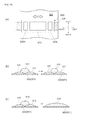
- a print unit 500 is shown in Fig. 10(a) .
- directions indicated by arrows shown in Fig. 10(a) will be defined as forward, backward, leftward, and rightward directions, respectively in the following description.
- the print unit 500 comprises mainly a print head 510 which ejects UV ink, a right ultraviolet light irradiation device 520R, a left ultraviolet light irradiation device 520L, and a carriage (not shown) on which these are disposed.
- UVLEDs are arranged so as to radiate ultraviolet light downwardly and are disposed and fixed on the right and left sides of the print head 510.
- the right ultraviolet light irradiation device 520R and the left ultraviolet light irradiation device 520L are designed to have a width in the front-back direction which is substantially the same as the width in the front-back direction of the print head 510.
- the print head 510 comprises, for example, print heads for respective colors (not shown) such as a magenta print head, an yellow print head, a cyan print head, and a black print head.
- UV ink droplets are ejected from the respective nozzles of the print heads for respective colors so that the UV ink droplets are superposed in predetermined patterns on a printing line 508 while reciprocating the print unit 500 above the printing line 508 a predetermined number of passes.
- the right ultraviolet light irradiation device 520R and the left ultraviolet light irradiation device 520L emit ultraviolet light.
- the printing line 508 is irradiated with the ultraviolet light so as to cure the UV ink deposited on the printing line 508.
- Figs. 10(b), 10(c) are sectional views showing states that UV ink droplets ejected from the print head 510 are deposited on the printing line 508 as mentioned above.
- Fig. 10(b) shows a state that uncured UV ink droplets 512 are ejected and deposited at the current pass on completely cured UV ink droplets 511, which were ejected and deposited at the last pass on the printing line 508 and which were irradiated with ultraviolet light and thus completely cured.
- the affinity of the uncured UV ink droplets 512 for the completely cured UV ink 511 are poor so that the uncured UV ink droplets 512 are deposited in a raised shape like beading because of surface tension.
- the uncured UV ink droplets 512 spread very little before irradiation with ultraviolet light because of poor affinity and is then completely cured in this state by irradiation with ultraviolet light.
- Fig. 10(c) shows a state that uncured UV ink droplets 514 are ejected and deposited at the current pass on uncured UV ink droplets 513, which were ejected and deposited at the last pass on the printing line 508 and which were not cured (or cured very little).
- the affinity of the later uncured UV ink droplets 514 for the prior uncured UV ink droplets 513 are good so that, after the later uncured UV ink droplets 514 are deposited in a beading state, the later uncured UV ink droplets 514 are mixed with the prior uncured UV ink droplets 513 and thus bleed.
- Patent document 1 discloses an arrangement in which, after the surfaces of ink droplets deposited on a recording medium 2 are cured by ultraviolet light emitted from first light irradiation devices 17, 18, 19, and 20, the ink droplets are completely cured by ultraviolet light emitted from a second light irradiation device 21.
- Patent document 1 JP-A-2004-276584
- UV ink droplets deposited and superposed on the print medium 501 are not mixed and thus do not bleed, but the UV ink droplets spread and are thus leveled.
- the print medium 501 with desired printing (desired printed matter) can be obtained.
- the uncured UV ink droplets 512 are superposed on and adhere to the completely cured UV ink droplets 511 as shown in Fig.
- the completely cured UV ink droplets 511 and the uncured UV ink droplets 512 are not mixed and thus do not bleed, but the completely cured UV ink droplets 511 reject the uncured UV ink droplets 512 so that the uncured UV ink droplets 512 may be cured by irradiation with ultraviolet light in the state remaining a raised shape like beading on the surface of the completely cured UV ink droplets 511.
- the printed matter in which UV ink droplets are cured in the state remaining the beading shape may have poorer print quality because reflection of light from the printed matter may differ so as to cause difference in vision.
- the later uncured UV ink droplets 514 When the later uncured UV ink droplets 514 are superposed on and adhere to the prior uncured UV ink droplets 513 as shown in Fig. 10(c) , the later uncured UV ink droplets 514 may be mixed with the prior uncured UV ink droplets 513 and thus bleed so that the UV ink droplets may be cured by irradiation with ultraviolet light in the mixed and bleeding state. As compared to the desired printed matter, the printed matter in which UV ink droplets are cured in the mixed and bleeding state may have poorer print quality because a mixed and bleeding portion of the printed matter has different color in vision.
- the present invention is made to address the aforementioned problems and it is an object of the present invention to provide an inkjet printer which has relatively simple structure and which can provide improved print quality by superposing UV ink droplets in a leveled state on a surface of a print medium and not to bleed and to provide a printing method using the inkjet printer.
- the present invention provides an inkjet printer comprising: a medium supporting means (for example, the platen 12a in the following embodiments) for supporting a print medium (for example, the print sheet 1 in the following embodiments); a print head for ejecting ink droplets toward the print medium supported by said medium supporting means; an ultraviolet light irradiation means (for example, the right ultraviolet light irradiation device 23R, the left ultraviolet light irradiation device 23L in the following embodiments) which irradiates the print medium with ultraviolet light to cure ink deposited on said print medium; and a carriage on which said print head and said ultraviolet light irradiation means are mounted to face said medium supporting means and which is allowed to be reciprocated in a first direction relative to the print medium and to be moved relative to the print medium in a second direction perpendicular to said first direction.
- a medium supporting means for example, the platen 12a in the following embodiments
- a print medium for example, the print sheet 1 in the following embodiments
- said ultraviolet light irradiation means is arranged on a side in said first direction of said print head, and said print head is arranged to project toward the upstream of a feeding direction in said second direction by a predetermined length relative to said ultraviolet light irradiation means.
- said print head is designed to eject a predetermined amount of ink to the print medium every time said print head is moved in said first direction by said carriage in a predetermined plural number of times, said predetermined amount corresponding to said predetermined plural number, and that, assuming that the width in said second direction of said print head is X and the predetermined plural number is A, said predetermined length is set to be larger than X/A.
- said carriage is designed to move relative to the print medium from one end to the other end in said first direction and then return from said other end to said one end and, at said one end, to be moved relative to said print medium in said second direction.
- said carriage may be designed to move relative to the print medium in said first direction from said one end to said other end and, at said other end, to be moved relative to said print medium in said second direction, and to move relative to the print medium in said first direction from said other end to said one end.
- said ultraviolet light irradiation means is composed of a plurality of LEDs (for example, the UVLED modules 31 in the following embodiments) emitting ultraviolet light which are aligned in said second direction, such that the number of LEDs arranged at the downstream of the feeding direction in the second direction is larger than the number of LEDs arranged at the upstream of the feeding direction.
- the intensity of ultraviolet light emitted from each of said LEDs is controllable, that said inkjet printer comprises an intensity controlling means (for example, the controller 13b in the following embodiments) for controlling the intensity of ultraviolet light emitted from each of said LEDs, and that said intensity controlling means conducts the light intensity control such that the intensity of said LED arranged at the downstream of the feeding direction in said second direction is higher than the intensity of said LED arranged at the upstream of the feeding direction.
- an intensity controlling means for example, the controller 13b in the following embodiments
- a printing method is a printing method using the aforementioned inkjet printer, wherein ink droplets are ejected to the print medium from the print head mounted on the carriage which are operated to reciprocate relative to the print medium in a first direction and to be moved relative to the print medium in a second direction perpendicular to said first direction, and the ink droplets are cured by irradiating the print medium with ultraviolet light from the ultraviolet light irradiation means mounted on said carriage so as to conduct printing.
- Said printing method comprises: a first step of ejecting ink droplets toward the print medium from a portion of said print head projecting toward the upstream of the feeding direction in the second direction relative to said ultraviolet light irradiation means, while moving said carriage relative to the print medium in said first direction; and a second step of moving said carriage relative to the print medium in said second direction, then ejecting ink droplets from a portion of said print head, on a side in said first direction of which said ultraviolet light irradiation means is positioned, while moving said carriage in said first direction, such that the ink droplets thus ejected are superposed on the ink droplets deposited in said first step, and irradiating the ink droplets with ultraviolet light from said ultraviolet light irradiation means so as to cure the ink droplets.
- the print head is mounted on the carriage in such a manner as to project toward the upstream of the feeding direction relative to the ultraviolet light irradiation means by the predetermined length.
- ink droplets which are ejected from a portion of the print head projecting toward the upstream of the feeding direction by the predetermined length during the movement of the carriage in the reciprocating direction perpendicular to the feeding direction are not directly irradiated with ultraviolet light because the ultraviolet light irradiation means does not pass above the ink droplets immediately after the ink droplets are deposited on the print medium.
- this is a simple structure that the print head and the ultraviolet light irradiation means on the carriage are arranged in the adjusted positions, but prevents the ink droplets in the beading shape deposited on the print medium from being cured in the beading shape immediately after the ink droplets are deposited and allows the ink droplets to enough spread and thus leveled on the surface of the print medium.
- the ink droplets deposited on the print medium are indirectly irradiated with a slight amount of ultraviolet light from the ultraviolet light irradiation means so that only the surfaces of the UV ink droplets deposited are cured, thereby preventing the UV ink droplets from bleeding due to mixture.
- the print head is designed to eject ink every time the print head is moved in the reciprocating direction by the carriage in a predetermined plural number of times, and that, assuming that the width in the feeding direction of the print head is X and the predetermined plural number is A, the predetermined length is set to be larger than X/A.
- the predetermined length is set to be larger than X/4 so that, when ink droplets are ejected onto a printing area where no ink has been deposited during printing, the ink droplets are prevented from being irradiated directly with ultraviolet light immediately after the ink droplets are ejected and deposited on this printing area. Therefore, the ink droplets in the beading shape are prevented from being cured in the beading shape immediately after the ink droplets are deposited and are allowed to enough spread and thus leveled on the surface of the print medium.
- the carriage is designed to move relative to the print medium from one end to the other end in the first direction and then return from the other end to the one end and, at the one end, to be moved relative to the print medium in the second direction.
- the print head is moved to deposit ink droplets not to create gaps relative to the print medium, thereby enabling high-quality printing.
- the carriage may be designed to be moved relative to the print medium in the second direction every time the carriage moves the one end or the other end. According to this arrangement, the print head can be moved relative to the print medium rapidly, thereby shortening the printing time.
- the LEDs composing the ultraviolet light irradiation means are arranged such that the number of LEDs arranged at the downstream of the feeding direction is larger than the number of LEDs arranged at the upstream of the feeding direction. According to this arrangement, the intensity of ultraviolet light irradiated from the downstream of the feeding direction of the ultraviolet light irradiation means can be set to be high. Therefore, the portion of the print medium on which ink droplets are deposited by all of the predetermined plural number of times can be irradiated with high-intensity ultraviolet light, thereby completely curing the ink droplets and thus securely fixing the ink droplets to the print medium.
- the ultraviolet light intensity is controlled by the intensity controlling means such that the intensity of the LED arranged at the downstream of the feeding direction is higher than the intensity of the LED arranged at the upstream of the feeding direction.
- the upstream of the feeding direction irradiates relatively low-intensity ultraviolet light
- the ink droplets are prevented from being completely cured and are allowed to enough spread and thus be leveled.
- the downstream of the feeding direction irradiates high-intensity ultraviolet light, the ink droplets are completely cured and securely fixed to the print medium.
- the printing method of the present invention comprises: a first step of ejecting ink droplets toward the print medium from a portion of the print head projecting toward the upstream side of the feeding direction relative to the ultraviolet light irradiation means; and a second step of ejecting ink droplets from a portion of the print head, on a side in the first direction of which the ultraviolet light irradiation means is positioned, such that the ink droplets thus ejected are superposed on the ink droplets deposited in the first step, and irradiating the ink droplets with ultraviolet light from the ultraviolet light irradiation means so as to cure the ink droplets.
- the ink droplets deposited in the breading shape on the print medium are prevented from being cured in the breading state immediately after the ink droplets are deposited and are allowed to enough spread and thus be leveled on the surface of the print medium.
- the ink droplets ejected in the second step are superposed on the ink droplets thus leveled and are cured, whereby the ink droplets can be cured in a state where these are leveled as a whole. Therefore, this arrangement enables high-quality printing not so different from a desired printed matter.
- first through fifth embodiments illustrates an arrangement in which printing is conducted by four passes (by superposing UV ink droplets four times).
- directions indicated by arrows will be defined as forward, backward, leftward, rightward, upward, and downward directions, respectively in the following description.
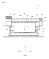
- FIG. 1 is an illustration of the inkjet printer 10 as seen from the front
- Fig. 2 is an illustration of the inkjet printer 10 as seen from the left side
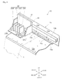
- Fig. 3 is an illustration of a portion around a print unit.
- the inkjet printer 10 comprises a supporting leg section 11 having left and right supporting legs 11a, 11b, a central body section 12 supported by the supporting leg section 11, a left body section 13 disposed on a left side of the central body section 12, and a right body section 14 disposed on a right side of the central body section 12, and an upper body section 15 which connects the left and right body sections 13, 14 and is disposed above the central body section 12 with some space and extends in parallel with the central body section 12.
- the central body section 12 is provided with a platen 12a which exposed on the upper surface of the central body section 12 and which extends in the right-left direction.
- Each clamping device 15a has a pinch roller 15c which is rotatably disposed at the front end of the clamping device 15a.
- a cylindrical feeding roller 12b extending in the right-left direction is disposed to exposed on the platen 12a and is driven to rotate by a roller driving motor (not shown) installed inside the central body section 12.
- Each clamping device 15a can be switched between a clamping position where the pinch roller 15c is pressed against the feeding roller 12b and an unclamping position where the pinch roller 15c is spaced apart from the feeding roller 12b.
- the print sheet 1 can be fed forward or backward for a desired distance.
- an operation panel 13a composed of operational switches, a display, and the like is attached to the front surface of the left body section 13 and a controller 13b is arranged inside the left body section 13.
- a controller 13b is arranged inside the left body section 13.
- operations of respective components for example, UVLED modules 31 as will be described later
- a cartridge mounting portion 16 is disposed to which a plurality of cartridge-type ink tanks 18 for respective colors are detachably attached from the front.
- a guide rail 15b extending in the right-left direction is arranged inside the upper body 15.
- a print unit 20 is installed such that the print unit 20 can be reciprocated in the right-left direction along the guide rail 15b.
- the print unit 20 is mainly composed of a carriage 21, a print head 22, and a left ultraviolet light irradiation device 23L, and a right ultraviolet light irradiation device 23R.
- the back of the carriage 21 is fitted with the guide rail 15b so as to reciprocate along the guide rail 15b in the right-left direction.
- the carriage 21 functions as a mounting base for the print head 22, the left ultraviolet light irradiation device 23L, and the right ultraviolet light irradiation device 23R.
- the print head 22 comprises, for example, print heads 22M, 22Y, 22C, and 22K for respective colors of magenta (M), yellow (Y), cyan (C), and black (K), which are connected to the aforementioned ink tanks 18 through rubber tubes.
- Each of the print heads 22M, 22Y, 22C, and 22K has a plurality of nozzle holes (not shown) formed in the lower surface thereof for ejecting UV ink downwardly.
- Fig. 4(a) is a sectional view of a portion IV(a)-IV(a) in Fig. 3
- Fig. 4(b) is a sectional view of a portion IV(b)-IV(b) in Fig. 4(a)
- Figs. 5(a) and 5(b) are illustrations of the print unit 20 as seen from above, respectively.
- the right ultraviolet light irradiation device 23R disposed on the right side of the print head 22 (22M) has the same structure as that of the left ultraviolet light irradiation device 23L so that the explanation of the right ultraviolet light irradiation device 23R will be omitted.
- the left ultraviolet light irradiation device 23L is mainly composed of, for example, a plurality of UVLED modules 31 which are aligned in the front-back direction and a cover 32 opening downwardly.
- each UVLED module 31 comprises a base portion 34, an UVLED chip 33 capable of emitting ultraviolet light which is fixed to the lower end of the base portion 34 and a module body 35, wherein the base portion 34 is inserted in the module body 35 through the top of the same and is fixed to the module body 35.
- the print sheet 1 is irradiated with ultraviolet light emitted from the UVLED chips 33.
- UVLED modules 31 are aligned in the front-back direction in the aforementioned example, the UVLED modules 31 may be set on a plain in the front-back direction and the right-left direction.
- the width in the front-back direction of the left ultraviolet light irradiation device 23L is substantially the same as the width X in the front-back direction of the print head 22.
- the print head 22 is mounted on the carriage 21 in a state projecting rearward by a projecting length X/4 relative to the left ultraviolet light irradiation device 23L.
- Figs. 5(a), 5(b) through Figs. 7(a)-7(e) are illustrations of the print unit 20 as seen from above and Figs. 7(a)-7(e) are sectional views showing states where UV ink droplets are superposed every pass. It should be noted that the printing method as will be described below is an example of a case that the printing is achieved by four passes.
- UV ink droplets are ejected from the nozzle holes formed in the lower surface of the print head 22 to the print sheet 1 put on the upper surface of the platen 12a while the print unit 20 is reciprocated in the right-left direction along the guide rail 15b relative to the print sheet 1, thereby depositing the UV ink droplets onto the print sheet 1 in a desired pattern.
- the right ultraviolet light irradiation device 23R is operated and, on the other hand, when the print unit 20 is moved rightward, the left ultraviolet light irradiation device 23L is operated to irradiate the print sheet 1 with ultraviolet light to cure the UV ink droplets deposited on the print sheet 1.
- Fig. 5(a) shows a state in a middle stage of the printing where the print unit 20 is positioned on the left side of the left end of the print sheet 1.
- the printing areas 1a through 1d in the print sheet 1 are in a non-printed state where no UV ink is deposited
- a printing area 1e is a state where ink by one pass (25%) is deposited
- a printing area If is a state where ink by two passes (50%) is deposited
- a printing area 1g is a state where ink by three passes (75%) is deposited
- a printing area 1h is a state where ink by four passes (100%) is deposited.
- the width in the front-back direction of each of the printing areas 1a through 1h corresponds to a projecting length X/4 of the print head 22 projecting rearward relative to the left ultraviolet light irradiation device 23L and corresponds to a feeding amount to be fed by the roller driving motor at one time as will be described later.
- UV ink for one pass (25%) is ejected from the nozzle holes formed in the lower surface of the print head 22 while the print unit 20 is moved rightward and the left ultraviolet light irradiation device 23L is operated to irradiate the print sheet 1 with ultraviolet light to cure UV ink deposited on the print sheet 1.
- the printing area 1d becomes a state where UV ink by one pass (25%) is deposited
- the printing area 1e becomes a state where UV ink by two passes (50%) is deposited
- the printing area If becomes a state where UV ink by three passes (75%) is deposited
- the printing area 1g becomes a state where UV ink by four passes (100%) is deposited.
- the printing areas 1e through 1h are irradiated with ultraviolet light from the left ultraviolet light irradiation device 23L to cure the deposited UV ink (hereinafter, this will be called "first pass").
- the printing area 1h is irradiated with ultraviolet light from the left ultraviolet light irradiation device 23L so as to securely cure the UV ink deposited on or before the last time and fix the UV ink to the print sheet 1.
- UV ink by one pass (25%) is deposited on the printing area 1d, but the printing area 1d is not directly irradiated with ultraviolet light because the left ultraviolet light irradiation device 23L does not pass above the printing area 1d. Therefore, UV ink droplets deposited in the beading shape on the surface of the printing area 1d enough spread and are thus leveled. By the way, the surface of the printing area 1d is irradiated with a slight amount of ultraviolet light leaking from the rear end of the left ultraviolet light irradiation device 23L.
- UV ink droplets 22a deposited in the beading shape on the printing area 1d shown in Fig. 7(a) can enough spread and are leveled during the movement of the print unit 20 to the right end of the print sheet 1, thereby preventing the UV ink droplets 22a from being mixed and bleeding like the UV ink droplets 22b shown in Fig. 7(b) .
- the roller driving motor is driven to feed the print sheet 1 forward by a distance (the projecting length X/4) corresponding to the width in the front-back direction of each printing area 1a-1h (see Fig. 5(b) ).
- a clearance may be generated relative to a printing by the next pass. To avoid this, it is preferable to feed the print sheet 1 by the projecting length X/4 plus slight extra length.
- UV ink for one pass is ejected from the nozzle holes while the print unit 20 is moved leftward and the right ultraviolet light irradiation device 23R is operated to irradiate the print sheet 1 with ultraviolet light so as cure the UV ink deposited on the print sheet 1. Therefore, by moving the print unit 20 to the left end of the print sheet 1, the printing area 1c becomes a state where UV ink by one pass is deposited, the printing area 1d becomes a state where UV ink by two passes is deposited, the printing area 1e becomes a state where UV ink by three passes is deposited, and the printing area 1f becomes a state where UV ink by four passes is deposited.
- UV ink droplets 22c are deposited or superposed on the UV ink droplets 22b which enough spread as shown in Fig. 7(c) . Since the surfaces of the UV ink droplets 22b are slightly cured as mentioned above, deposited UV ink droplets 22c do not mixed with the UV ink droplets 22b and thus do not bleed and, in addition, spread on the surfaces of the UV ink droplets 22b to some degree. Since affinity of the UV ink droplets 22b for the UV ink droplets 22c is relatively good so that the UV ink droplets 22b and the UV ink droplets 22c do not reject each other, the adhesion between the UV ink droplets 22b and the UV ink droplets 22c is improved.
- the UV ink droplets 22b and the UV ink droplets 22c are irradiated with ultraviolet light from the right ultraviolet light irradiation device 23R in a state where these ink droplets enough spread and enough adhere to each other (hereinafter, this will be called "second pass").
- the roller driving motor is driven to feed the print sheet 1 forward (see Fig. 6(a) ).
- UV ink for one pass is ejected while the print unit 20 is moved rightward and the left ultraviolet light irradiation device 23L is operated.
- the printing area 1b becomes a state where UV ink by one pass is deposited
- the printing area 1c becomes a state where UV ink by two passes is deposited
- the printing area 1d becomes a state where UV ink by three passes is deposited
- the printing area 1e becomes a state where UV ink by four passes is deposited.
- UV ink droplets 22d are deposited or superposed on the UV ink droplets 22b and the UV ink droplets 22c, which are cured in the leveled state as shown in Fig. 7(d) , and are then irradiated with ultraviolet light from the left ultraviolet light irradiation device 23L so that these UV ink droplets are cured (hereinafter, this will be called "third pass").
- the roller driving motor is driven to feed the print sheet 1 forward (see Fig. 6(b) ).
- UV ink for one pass is ejected while the print unit 20 is moved leftward and the right ultraviolet light irradiation device 23R is operated. Therefore, by moving the print unit 20 to the left end of the print sheet 1, the printing area 1a becomes a state where UV ink by one pass is deposited, the printing area 1b becomes a state where UV ink by two passes is deposited, the printing area 1c becomes a state where UV ink by three passes is deposited, and the printing area 1d becomes a state where UV ink by four passes is deposited.
- UV ink droplets 22e are deposited or superposed on the UV ink droplets 22b, 22c, and 22d, which are cured as shown in Fig. 7(e) , and are then irradiated with ultraviolet light from the right ultraviolet light irradiation device 23R so that these UV ink droplets are cured (hereinafter, this will be called "fourth pass”). It should be understood that the UV ink droplets 22b, 22c, 22d, and 22e are completely cured and fixed to the print sheet 1 by irradiation of ultraviolet light from the left ultraviolet light irradiation device 23L at the next pass, thus completing the printing relative to the printing area 1d.
- UV ink droplets ejected at the second through fourth passes are sequentially deposited and superposed on each other in the state that the UV ink droplets are enough leveled as mentioned above, the UV ink droplets can be cured in a state where these are leveled as a whole as compared to a case that UV ink droplets are sequentially superposed on UV ink droplets which are cured in the state remaining the beading shape. Accordingly, this is a simple structure that the print head 22 is arranged to shift rearward relative to the right ultraviolet light irradiation device 23R (the left ultraviolet light irradiation device 23L), but enables high-quality printing having visual appearance as good as a desired printed matter.
- FIG. 8(a) shows an illustration of a print unit as seen from above. Since the structure of the second embodiment is the same as the aforementioned first embodiment, except the print unit, description about the same components as those of the first embodiment will be omitted by using the same numerals. The same is true for the third through fifth embodiments as will be described later.
- a print unit 60 having different structure from that of the first embodiment 1 will be described.
- the print unit 60 is mainly composed of a carriage 21, a print head 22, and a left ultraviolet light irradiation device 63L, and a right ultraviolet light irradiation device 63R. Since the left ultraviolet light irradiation device 63L and the right ultraviolet light irradiation device 63R have the same structure, description will be made as regard to the left ultraviolet light irradiation device 63L.
- the front end position of the left ultraviolet light irradiation device 63L is substantially equal to the front end position of the print head 22 and the print head 22 projects rearward relative to the left ultraviolet light irradiation device 63L by a projecting length X/4.
- the same effect as the first embodiment can be obtained and, in addition, the width in the front-back direction of the left ultraviolet light irradiation device 63L and the right ultraviolet light irradiation device 63R can be reduced, thereby achieving the print unit 60 which is compact in the front-back direction.
- the print unit 70 is mainly composed of a carriage 21, a print head 22, and a left ultraviolet light irradiation device 73L, and a right ultraviolet light irradiation device 73R. Description will be made as regard to the left ultraviolet light irradiation device 73L.
- the front end position of the left ultraviolet light irradiation device 73L is substantially equal to the front end position of the print head 22 and the print head 22 projects rearward relative to the left ultraviolet light irradiation device 73L by a projecting length X/4.
- the left ultraviolet light irradiation device 73L has such a structure that the number of UVLED modules 31 arranged is increased toward the front end.
- three UVLED modules 31 are arranged in a front area 73a at the front end side, two UVLED modules 31 are arranged in a middle area following the front area 73a, and one UVLED module 31 is arranged in a rear area following the middle area 73b.
- the front area 73a, the middle area 73b, and the rear area 73c each have the width X/4 in the front-back direction.
- ultraviolet light of intensity proportional to the number of UVLED modules 31 arranged is radiated by operating the respective UVLED modules 31 during the printing.
- ultraviolet light of high intensity is radiated from the front area 73a
- ultraviolet light of low intensity is radiated from the rear area 73c
- ultraviolet light of medium intensity is irradiated from the middle area 73b. Therefore, irradiation of ultraviolet light is not conducted on the first pass, and UV ink droplets are irradiated with ultraviolet light of intensity increased as it goes from the second pass to the fourth pass and are thus cured.
- UV ink droplets deposited in the first through third passes are irradiated with ultraviolet light of which intensity is low, i.e.
- UV ink droplets are not enough for completely curing the UV ink droplets, so as to prevent the UV ink droplet from bleeding and to level the UV ink droplets sufficiently.
- ultraviolet light of which intensity is enough for complete curing is radiated, thereby achieving printing capable of completely curing all UV ink droplets deposited in the first through fourth passes.
- the UV ink droplets are cured in a state that these are leveled as a whole, thereby achieving high-quality printing having visual appearance as good as a desired printed matter.
- the print unit 80 is mainly composed of a carriage 21, a print head 22, and a left ultraviolet light irradiation device 83L, and a right ultraviolet light irradiation device 83R. Description will be made as regard to the left ultraviolet light irradiation device 83L.
- the front end position of the left ultraviolet light irradiation device 83L is substantially equal to the front end position of the print head 22 and the print head 22 projects rearward relative to the left ultraviolet light irradiation device 83L by a projecting distance X/4.
- the left ultraviolet light irradiation device 83L three UVLED modules 31 are aligned in the right-left direction in each of a front area 83a, a middle area 83b, and a rear area 83c of which width in the front-back direction is X/4.
- the UVLED modules 31 are controlled by a controller 13b in such a manner that three of the UVLED modules 31 in the front area 83a, two of the UVLED modules 31 in the middle area 83b, and one of the UVLED modules 31 in the rear area 83c.
- the UVLED modules 31 which are controlled to be operated are hatched in Fig. 9(a) .
- ultraviolet light of high intensity is radiated from the front area 83a
- ultraviolet light of low intensity is radiated from the rear area 83c
- ultraviolet light of medium intensity is irradiated from the middle area 83b, thereby obtaining the same effects as the third embodiment.
- the print unit 90 is mainly composed of a carriage 21, a print head 22, and a left ultraviolet light irradiation device 93L, and a right ultraviolet light irradiation device 93R. Description will be made as regard to the left ultraviolet light irradiation device 93L.
- the front end position of the left ultraviolet light irradiation device 93L is substantially equal to the front end position of the print head 22 and the print head 22 projects rearward relative to the left ultraviolet light irradiation device 83L by a projecting length X/4.
- three UVLED modules 31 are aligned in the right-left direction in each of a front area 93a, a middle area 93b, and a rear area 93c of which width in the front-back direction is X/4.
- the intensities of ultraviolet lights emitted from the UVLED modules 31 are controlled by a controller 13b.
- the intensity control is conducted such that, for example, the three UVLED modules 31 in the front area 93a radiate ultraviolet light of high intensity, the three UVLED modules 31 in the middle area 93b radiate ultraviolet light of medium intensity, and the three UVLED modules 31 in the rear area 93c radiate ultraviolet light of low intensity.
- ultraviolet light of high intensity is radiated from the front area 93a
- ultraviolet light of medium intensity is irradiated from the middle area 93b
- ultraviolet light of low intensity is radiated from the rear area 93c, thereby obtaining the same effects as the third embodiment.
- a combination of the third embodiment and the fifth embodiment may be employed.
- three UVLED modules 31 are arranged in the front area 73a, two UVLED modules 31 are arranged in the middle area 73b, and one UVLED module 31 is arranged in the rear area 73c.
- the intensities of ultraviolet light radiated from the respective UVLED modules 31 are controlled by the controller 13b.
- the UVLED modules 31 are controlled such that, for example, the ultraviolet light from the front area 73a has high intensity, the ultraviolet light from the middle area 73b has medium intensity, and the ultraviolet light from the rear area 73c has low intensity.
- the intensity of ultraviolet light radiated from the rear area 73c can be set lower than that of the third embodiment and the intensity of ultraviolet light radiated from the front area 73a can be set higher than that of the third embodiment.
- certain kinds of UV inks require ultraviolet light of relatively high intensity to completely cure. This arrangement effects in case of using such kind of UV ink.
- the present invention is not limited to this printing method.
- the projecting length is set to X/8 and the amount of the print sheet 1 to be fed at once by the roller driving motor is set X/8, thereby enabling the printing to which the present invention is applied.
- the present invention is not limited to this arrangement.
- the print unit 20 is moved to the right end of the print sheet 1 while UV ink of a half of one pass (12.5%) is ejected from the print head 22 and, after that, the print unit 20 is moved to the left end of the print sheet 1 without moving the print sheet 1 forward so that the print sheet 1 remains at the same position in the front-back direction.
- UV ink for one pass (25%) is deposited on the printing area 1d.
- the print sheet 1 is fed forward and the print unit 20 is reciprocated in the right-left direction while ejecting UV ink of 12.5% from the print head 22 again.
- the print unit 20 is reciprocated in the right-left direction while ejecting UV ink of 12.5% from the print head 22 again.
- the amount of UV ink deposited on the print sheet 1 at one time can be reduced, thereby reducing the bleed between deposited UV ink droplets.
- the present invention is not limited to this arrangement.
- the present invention may be applied to an inkjet printer of so-called flat bed type in which printing is conducted by reciprocating a print unit in the right-left direction and moving the print unit in the front-rear direction in a state a print medium is put on and fixed to a tabular bed.
- the present invention is not limited this arrangement.
- an arrangement in which the left ultraviolet light irradiation device (the right ultraviolet light irradiation device) projects forward relative to the print head 22 may be employed.
Landscapes
- Health & Medical Sciences (AREA)
- General Health & Medical Sciences (AREA)
- Toxicology (AREA)
- Physics & Mathematics (AREA)
- Electromagnetism (AREA)
- Ink Jet (AREA)
- Ink Jet Recording Methods And Recording Media Thereof (AREA)
Abstract
Description
- The present invention relates to an inkjet printer which ejects ink droplets to a print medium, thereby conducting printing and relates to a printing method using the same.
- Conventionally, there is known an inkjet printer in which ink is ejected from a print head onto a print medium put on a platen while reciprocating the print head in a right-left direction so as to print the print medium. As one of such inkjet printers, there is a printer of a type ejecting ultraviolet curable ink (hereinafter, referred to as UV ink) having a property that it is cured when irradiated with ultraviolet light. Since the UV ink has excellent weather resistance and excellent water resistance, the UV ink allows printed matters to be used as outdoor advertising posters or the like. Therefore, the UV ink has the advantage that the use of printed matters printed with UV ink dramatically increases the range of purposes as compared to printed matters printed with water-soluble ink. Generally, such an inkjet printer of a type ejecting UV ink is provided with an ultraviolet light irradiation device for curing the UV ink deposited on a print medium. In recent years, an inkjet printer has been developed in which an ultraviolet light emitting diode (hereinafter, referred to as UVLED) is used as a light source for emitting ultraviolet light in the ultraviolet light irradiation device.
- As an example of the conventional print unit, a
print unit 500 is shown inFig. 10(a) . For convenience of explanation, directions indicated by arrows shown inFig. 10(a) will be defined as forward, backward, leftward, and rightward directions, respectively in the following description. Theprint unit 500 comprises mainly aprint head 510 which ejects UV ink, a right ultravioletlight irradiation device 520R, a left ultravioletlight irradiation device 520L, and a carriage (not shown) on which these are disposed. Inside the right ultravioletlight irradiation device 520R and the left ultravioletlight irradiation device 520L, UVLEDs are arranged so as to radiate ultraviolet light downwardly and are disposed and fixed on the right and left sides of theprint head 510. The right ultravioletlight irradiation device 520R and the left ultravioletlight irradiation device 520L are designed to have a width in the front-back direction which is substantially the same as the width in the front-back direction of theprint head 510. Theprint head 510 comprises, for example, print heads for respective colors (not shown) such as a magenta print head, an yellow print head, a cyan print head, and a black print head. - To conduct printing on a
printing line 508 of theprint medium 501 by using theaforementioned print unit 500, UV ink droplets are ejected from the respective nozzles of the print heads for respective colors so that the UV ink droplets are superposed in predetermined patterns on aprinting line 508 while reciprocating theprint unit 500 above the printing line 508 a predetermined number of passes. During this, the right ultravioletlight irradiation device 520R and the left ultravioletlight irradiation device 520L emit ultraviolet light. Theprinting line 508 is irradiated with the ultraviolet light so as to cure the UV ink deposited on theprinting line 508. -
Figs. 10(b), 10(c) are sectional views showing states that UV ink droplets ejected from theprint head 510 are deposited on theprinting line 508 as mentioned above.Fig. 10(b) shows a state that uncuredUV ink droplets 512 are ejected and deposited at the current pass on completely curedUV ink droplets 511, which were ejected and deposited at the last pass on theprinting line 508 and which were irradiated with ultraviolet light and thus completely cured. Since theUV ink droplets 511 are completely cured, the affinity of the uncuredUV ink droplets 512 for the completely curedUV ink 511 are poor so that the uncuredUV ink droplets 512 are deposited in a raised shape like beading because of surface tension. After the uncuredUV ink droplets 512 are deposited in a beading state, the uncuredUV ink droplets 512 spread very little before irradiation with ultraviolet light because of poor affinity and is then completely cured in this state by irradiation with ultraviolet light. - On the other hand,
Fig. 10(c) shows a state that uncuredUV ink droplets 514 are ejected and deposited at the current pass on uncuredUV ink droplets 513, which were ejected and deposited at the last pass on theprinting line 508 and which were not cured (or cured very little). The affinity of the later uncuredUV ink droplets 514 for the prior uncuredUV ink droplets 513 are good so that, after the later uncuredUV ink droplets 514 are deposited in a beading state, the later uncuredUV ink droplets 514 are mixed with the prior uncuredUV ink droplets 513 and thus bleed. The later uncuredUV ink droplets 514 and the prior uncuredUV ink droplets 513 are mixed so as to form a mixed UV ink 515. The mixed UV ink 515 is irradiated with ultraviolet light and is thus completely cured. To prevent UV ink from bleeding as mentioned above, for example,Patent document 1 discloses an arrangement in which, after the surfaces of ink droplets deposited on a recording medium 2 are cured by ultraviolet light emitted from firstlight irradiation devices light irradiation device 21. - Patent document 1:
JP-A-2004-276584 - By the way, for printing on the
print medium 501 by theprint unit 500, it is preferable that UV ink droplets deposited and superposed on theprint medium 501 are not mixed and thus do not bleed, but the UV ink droplets spread and are thus leveled. In this case, theprint medium 501 with desired printing (desired printed matter) can be obtained. However, when the uncuredUV ink droplets 512 are superposed on and adhere to the completely curedUV ink droplets 511 as shown inFig. 10(b) , the completely curedUV ink droplets 511 and the uncuredUV ink droplets 512 are not mixed and thus do not bleed, but the completely curedUV ink droplets 511 reject the uncuredUV ink droplets 512 so that the uncuredUV ink droplets 512 may be cured by irradiation with ultraviolet light in the state remaining a raised shape like beading on the surface of the completely curedUV ink droplets 511. As compared to the desired printed matter, the printed matter in which UV ink droplets are cured in the state remaining the beading shape may have poorer print quality because reflection of light from the printed matter may differ so as to cause difference in vision. - When the later uncured
UV ink droplets 514 are superposed on and adhere to the prior uncuredUV ink droplets 513 as shown inFig. 10(c) , the later uncuredUV ink droplets 514 may be mixed with the prior uncuredUV ink droplets 513 and thus bleed so that the UV ink droplets may be cured by irradiation with ultraviolet light in the mixed and bleeding state. As compared to the desired printed matter, the printed matter in which UV ink droplets are cured in the mixed and bleeding state may have poorer print quality because a mixed and bleeding portion of the printed matter has different color in vision. - The present invention is made to address the aforementioned problems and it is an object of the present invention to provide an inkjet printer which has relatively simple structure and which can provide improved print quality by superposing UV ink droplets in a leveled state on a surface of a print medium and not to bleed and to provide a printing method using the inkjet printer.
- To achieve the aforementioned object, the present invention provides an inkjet printer comprising: a medium supporting means (for example, the
platen 12a in the following embodiments) for supporting a print medium (for example, theprint sheet 1 in the following embodiments); a print head for ejecting ink droplets toward the print medium supported by said medium supporting means; an ultraviolet light irradiation means (for example, the right ultravioletlight irradiation device 23R, the left ultravioletlight irradiation device 23L in the following embodiments) which irradiates the print medium with ultraviolet light to cure ink deposited on said print medium; and a carriage on which said print head and said ultraviolet light irradiation means are mounted to face said medium supporting means and which is allowed to be reciprocated in a first direction relative to the print medium and to be moved relative to the print medium in a second direction perpendicular to said first direction. On said carriage, said ultraviolet light irradiation means is arranged on a side in said first direction of said print head, and said print head is arranged to project toward the upstream of a feeding direction in said second direction by a predetermined length relative to said ultraviolet light irradiation means. - In the aforementioned inkjet printer, it is preferable that said print head is designed to eject a predetermined amount of ink to the print medium every time said print head is moved in said first direction by said carriage in a predetermined plural number of times, said predetermined amount corresponding to said predetermined plural number, and that, assuming that the width in said second direction of said print head is X and the predetermined plural number is A, said predetermined length is set to be larger than X/A.
- Further, in the aforementioned inkjet printer, it is preferable that said carriage is designed to move relative to the print medium from one end to the other end in said first direction and then return from said other end to said one end and, at said one end, to be moved relative to said print medium in said second direction.
- In the aforementioned inkjet printer, said carriage may be designed to move relative to the print medium in said first direction from said one end to said other end and, at said other end, to be moved relative to said print medium in said second direction, and to move relative to the print medium in said first direction from said other end to said one end.
- Further, in the aforementioned inkjet printer, it is preferable that said ultraviolet light irradiation means is composed of a plurality of LEDs (for example, the
UVLED modules 31 in the following embodiments) emitting ultraviolet light which are aligned in said second direction, such that the number of LEDs arranged at the downstream of the feeding direction in the second direction is larger than the number of LEDs arranged at the upstream of the feeding direction. - Furthermore, in the aforementioned inkjet printer, it is preferable that the intensity of ultraviolet light emitted from each of said LEDs is controllable, that said inkjet printer comprises an intensity controlling means (for example, the
controller 13b in the following embodiments) for controlling the intensity of ultraviolet light emitted from each of said LEDs, and that said intensity controlling means conducts the light intensity control such that the intensity of said LED arranged at the downstream of the feeding direction in said second direction is higher than the intensity of said LED arranged at the upstream of the feeding direction. - A printing method according to the present invention is a printing method using the aforementioned inkjet printer, wherein ink droplets are ejected to the print medium from the print head mounted on the carriage which are operated to reciprocate relative to the print medium in a first direction and to be moved relative to the print medium in a second direction perpendicular to said first direction, and the ink droplets are cured by irradiating the print medium with ultraviolet light from the ultraviolet light irradiation means mounted on said carriage so as to conduct printing. Said printing method comprises: a first step of ejecting ink droplets toward the print medium from a portion of said print head projecting toward the upstream of the feeding direction in the second direction relative to said ultraviolet light irradiation means, while moving said carriage relative to the print medium in said first direction; and a second step of moving said carriage relative to the print medium in said second direction, then ejecting ink droplets from a portion of said print head, on a side in said first direction of which said ultraviolet light irradiation means is positioned, while moving said carriage in said first direction, such that the ink droplets thus ejected are superposed on the ink droplets deposited in said first step, and irradiating the ink droplets with ultraviolet light from said ultraviolet light irradiation means so as to cure the ink droplets.
- In the inkjet printer according to the present invention, the print head is mounted on the carriage in such a manner as to project toward the upstream of the feeding direction relative to the ultraviolet light irradiation means by the predetermined length. According to this arrangement, ink droplets which are ejected from a portion of the print head projecting toward the upstream of the feeding direction by the predetermined length during the movement of the carriage in the reciprocating direction perpendicular to the feeding direction are not directly irradiated with ultraviolet light because the ultraviolet light irradiation means does not pass above the ink droplets immediately after the ink droplets are deposited on the print medium. Accordingly, this is a simple structure that the print head and the ultraviolet light irradiation means on the carriage are arranged in the adjusted positions, but prevents the ink droplets in the beading shape deposited on the print medium from being cured in the beading shape immediately after the ink droplets are deposited and allows the ink droplets to enough spread and thus leveled on the surface of the print medium. Moreover, the ink droplets deposited on the print medium are indirectly irradiated with a slight amount of ultraviolet light from the ultraviolet light irradiation means so that only the surfaces of the UV ink droplets deposited are cured, thereby preventing the UV ink droplets from bleeding due to mixture.
- It is preferable that the print head is designed to eject ink every time the print head is moved in the reciprocating direction by the carriage in a predetermined plural number of times, and that, assuming that the width in the feeding direction of the print head is X and the predetermined plural number is A, the predetermined length is set to be larger than X/A. In case that ink is ejected in four batches, the predetermined length is set to be larger than X/4 so that, when ink droplets are ejected onto a printing area where no ink has been deposited during printing, the ink droplets are prevented from being irradiated directly with ultraviolet light immediately after the ink droplets are ejected and deposited on this printing area. Therefore, the ink droplets in the beading shape are prevented from being cured in the beading shape immediately after the ink droplets are deposited and are allowed to enough spread and thus leveled on the surface of the print medium.
- It is preferable that the carriage is designed to move relative to the print medium from one end to the other end in the first direction and then return from the other end to the one end and, at the one end, to be moved relative to the print medium in the second direction. According to this arrangement, the print head is moved to deposit ink droplets not to create gaps relative to the print medium, thereby enabling high-quality printing.
- Alternatively, the carriage may be designed to be moved relative to the print medium in the second direction every time the carriage moves the one end or the other end. According to this arrangement, the print head can be moved relative to the print medium rapidly, thereby shortening the printing time.
- Further, it is preferable that the LEDs composing the ultraviolet light irradiation means are arranged such that the number of LEDs arranged at the downstream of the feeding direction is larger than the number of LEDs arranged at the upstream of the feeding direction. According to this arrangement, the intensity of ultraviolet light irradiated from the downstream of the feeding direction of the ultraviolet light irradiation means can be set to be high. Therefore, the portion of the print medium on which ink droplets are deposited by all of the predetermined plural number of times can be irradiated with high-intensity ultraviolet light, thereby completely curing the ink droplets and thus securely fixing the ink droplets to the print medium.
- Furthermore, it is preferable that the ultraviolet light intensity is controlled by the intensity controlling means such that the intensity of the LED arranged at the downstream of the feeding direction is higher than the intensity of the LED arranged at the upstream of the feeding direction. According to this arrangement, since the upstream of the feeding direction irradiates relatively low-intensity ultraviolet light, the ink droplets are prevented from being completely cured and are allowed to enough spread and thus be leveled. In addition, since the downstream of the feeding direction irradiates high-intensity ultraviolet light, the ink droplets are completely cured and securely fixed to the print medium.
- The printing method of the present invention comprises: a first step of ejecting ink droplets toward the print medium from a portion of the print head projecting toward the upstream side of the feeding direction relative to the ultraviolet light irradiation means; and a second step of ejecting ink droplets from a portion of the print head, on a side in the first direction of which the ultraviolet light irradiation means is positioned, such that the ink droplets thus ejected are superposed on the ink droplets deposited in the first step, and irradiating the ink droplets with ultraviolet light from the ultraviolet light irradiation means so as to cure the ink droplets. Accordingly, the ink droplets deposited in the breading shape on the print medium are prevented from being cured in the breading state immediately after the ink droplets are deposited and are allowed to enough spread and thus be leveled on the surface of the print medium. In addition, the ink droplets ejected in the second step are superposed on the ink droplets thus leveled and are cured, whereby the ink droplets can be cured in a state where these are leveled as a whole. Therefore, this arrangement enables high-quality printing not so different from a desired printed matter.
-
- [
Fig. 1] Fig. 1 is a front view showing an inkjet printer according to the present invention. - [
Fig. 2] Fig. 2 is a side view of the inkjet printer. - [
Fig. 3] Fig. 3 is a perspective view showing a portion around a print unit. - [
Fig. 4] Fig. 4(a) is a sectional view taken along a line IV(a)-IV(a) inFig. 3 andFig. 4(b) is a sectional view taken along a line IV(b)-IV(b) inFig. 4(a) . - [
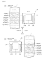
Fig. 5] Figs. 5(a)-5(b) are schematic illustrations for explaining a printing method by four passes, whereinFig. 5(a) shows a state of the first pass andFig. 5(b) shows a state of the second pass. - [
Fig. 6] Figs. 6(a)-6(b) are schematic illustrations for explaining a printing method by four passes, whereinFig. 6(a) shows a state of the third pass andFig. 6(b) shows a state of the fourth pass. - [
Fig. 7] Figs. 7(a)-7(e) are sectional views schematically showing a state where UV ink droplets are superposed fromFig. 7(a) to Fig. 7(e) according to the passes. - [
Fig. 8] Fig. 8(a) is a plan view showing a print unit according to a second embodiment andFig. 8(b) is a plan view showing a print unit according to a third embodiment. - [
Fig. 9] Fig. 9(a) is a plan view showing a print unit according to a fourth embodiment andFig. 9(b) is a plan view showing a print unit according to a fifth embodiment. - [
Fig. 10] Fig. 10(a) is a plan view showing a conventional print unit,Fig. 10(b) is a sectional view showing a state that UV ink droplets are deposited on completely cured UV ink droplets, andFig. 10 (c) is a sectional view showing a state that UV ink droplets are deposited on uncured UV ink droplets. - Hereinafter, preferred embodiments according to the present invention will be described with reference to attached drawings by means of first through fifth embodiments as examples. Each of the first through fifth embodiments as will be described below illustrates an arrangement in which printing is conducted by four passes (by superposing UV ink droplets four times). For convenience of explanation, in each figure, directions indicated by arrows will be defined as forward, backward, leftward, rightward, upward, and downward directions, respectively in the following description.
- With reference to
Fig. 1 through Fig. 3 , the entire structure of aninkjet printer 10 as an example of the printer according to the present invention will be described.Fig. 1 is an illustration of theinkjet printer 10 as seen from the front,Fig. 2 is an illustration of theinkjet printer 10 as seen from the left side, andFig. 3 is an illustration of a portion around a print unit. - As shown in
Fig. 1 , theinkjet printer 10 comprises a supportingleg section 11 having left and right supportinglegs central body section 12 supported by the supportingleg section 11, aleft body section 13 disposed on a left side of thecentral body section 12, and aright body section 14 disposed on a right side of thecentral body section 12, and anupper body section 15 which connects the left andright body sections central body section 12 with some space and extends in parallel with thecentral body section 12. Thecentral body section 12 is provided with aplaten 12a which exposed on the upper surface of thecentral body section 12 and which extends in the right-left direction. - At a lower portion of the
upper body section 15, a plurality ofclamping devices 15a are aligned in the right-left direction (seeFig. 3 ). Eachclamping device 15a has apinch roller 15c which is rotatably disposed at the front end of theclamping device 15a. Below thepinch roller 15c, acylindrical feeding roller 12b extending in the right-left direction is disposed to exposed on theplaten 12a and is driven to rotate by a roller driving motor (not shown) installed inside thecentral body section 12. Eachclamping device 15a can be switched between a clamping position where thepinch roller 15c is pressed against the feedingroller 12b and an unclamping position where thepinch roller 15c is spaced apart from the feedingroller 12b. According to this structure, by driving the roller driving motor in a state that theprint sheet 1 as a long sheet-like print subject is sandwiched between thepinch rollers 15c and the feedingroller 12b and theclamping devices 15a are set in their clamping positions, theprint sheet 1 can be fed forward or backward for a desired distance. - As shown in
Fig. 1 , anoperation panel 13a composed of operational switches, a display, and the like is attached to the front surface of theleft body section 13 and acontroller 13b is arranged inside theleft body section 13. By thiscontroller 13b, operations of respective components (for example,UVLED modules 31 as will be described later) of theinkjet printer 10 are controlled. At an upper portion of theright body section 14, acartridge mounting portion 16 is disposed to which a plurality of cartridge-type ink tanks 18 for respective colors are detachably attached from the front. As shown inFig. 3 , aguide rail 15b extending in the right-left direction is arranged inside theupper body 15. Aprint unit 20 is installed such that theprint unit 20 can be reciprocated in the right-left direction along theguide rail 15b. - As shown in
Fig. 3 , theprint unit 20 is mainly composed of acarriage 21, aprint head 22, and a left ultravioletlight irradiation device 23L, and a right ultravioletlight irradiation device 23R. The back of thecarriage 21 is fitted with theguide rail 15b so as to reciprocate along theguide rail 15b in the right-left direction. In addition, thecarriage 21 functions as a mounting base for theprint head 22, the left ultravioletlight irradiation device 23L, and the right ultravioletlight irradiation device 23R. Theprint head 22 comprises, for example,print heads aforementioned ink tanks 18 through rubber tubes. Each of theprint heads - Hereinafter, the left ultraviolet
light irradiation device 23L disposed on the left side of the print head 22 (22K) will be described with reference toFigs. 4(a), 4(b) andFigs. 5(a), 5(b) in addition toFig. 1 through Fig. 3 .Fig. 4(a) is a sectional view of a portion IV(a)-IV(a) inFig. 3 ,Fig. 4(b) is a sectional view of a portion IV(b)-IV(b) inFig. 4(a) ,Figs. 5(a) and 5(b) are illustrations of theprint unit 20 as seen from above, respectively. It should be noted that the right ultravioletlight irradiation device 23R disposed on the right side of the print head 22 (22M) has the same structure as that of the left ultravioletlight irradiation device 23L so that the explanation of the right ultravioletlight irradiation device 23R will be omitted. - As shown in
Fig. 4(a) , the left ultravioletlight irradiation device 23L is mainly composed of, for example, a plurality ofUVLED modules 31 which are aligned in the front-back direction and acover 32 opening downwardly. As shown inFig. 4(b) , eachUVLED module 31 comprises abase portion 34, anUVLED chip 33 capable of emitting ultraviolet light which is fixed to the lower end of thebase portion 34 and amodule body 35, wherein thebase portion 34 is inserted in themodule body 35 through the top of the same and is fixed to themodule body 35. According to this structure, theprint sheet 1 is irradiated with ultraviolet light emitted from the UVLED chips 33. It should be noted that another arrangement may be employed which comprises an optical lens (not shown) which is fixed to themodule body 35 below the UVLED chips 33 and a sealing resin (not shown) filled in a range surrounded by thebase portion 34, themodule body 35, and the optical lens. In this case, ultraviolet light emitted from theUVLED chip 33 is radiated downwardly at a predetermined radiation angle through the optical lens. Though theUVLED modules 31 are aligned in the front-back direction in the aforementioned example, theUVLED modules 31 may be set on a plain in the front-back direction and the right-left direction. - As shown in
Fig. 5(a) , the width in the front-back direction of the left ultravioletlight irradiation device 23L is substantially the same as the width X in the front-back direction of theprint head 22. In case of printing by four passes, theprint head 22 is mounted on thecarriage 21 in a state projecting rearward by a projecting length X/4 relative to the left ultravioletlight irradiation device 23L. - Though the entire structure of the
inkjet printer 10 has been described in the above, a printing method in case of printing on theprint sheet 1 by theaforementioned print unit 20 will be described with reference toFigs. 5(a), 5(b) throughFigs. 7(a)-7(e) below.Figs. 6(a) and 6(b) are illustrations of theprint unit 20 as seen from above andFigs. 7(a)-7(e) are sectional views showing states where UV ink droplets are superposed every pass. It should be noted that the printing method as will be described below is an example of a case that the printing is achieved by four passes. - First, the printing method will be explained roughly. As shown in
Fig. 3 , UV ink droplets are ejected from the nozzle holes formed in the lower surface of theprint head 22 to theprint sheet 1 put on the upper surface of theplaten 12a while theprint unit 20 is reciprocated in the right-left direction along theguide rail 15b relative to theprint sheet 1, thereby depositing the UV ink droplets onto theprint sheet 1 in a desired pattern. When theprint unit 20 is moved leftward, the right ultravioletlight irradiation device 23R is operated and, on the other hand, when theprint unit 20 is moved rightward, the left ultravioletlight irradiation device 23L is operated to irradiate theprint sheet 1 with ultraviolet light to cure the UV ink droplets deposited on theprint sheet 1. - By the way, if UV ink of 100% of the amount for printing the desired pattern is ejected at once, a large amount of UV ink droplets are deposited in the uncured state on the surface of the
print sheet 1 so that the UV ink droplets are mixed with each other and thus bleed because the UV ink droplets are uncured, thus leading to poor print quality. In theinkjet printer 10, therefore, ink of 25% is ejected from theprint head 22 while theprint unit 20 is reciprocated in the right-left direction. In this manner, theprint head 22 passes above theprint sheet 1 four times in total so as to apply ink of 100% finally, thereby conducting the printing without bleed of ink as mentioned above. This printing method will be described in detail below. -
Fig. 5(a) shows a state in a middle stage of the printing where theprint unit 20 is positioned on the left side of the left end of theprint sheet 1. At this point, it is assumed that theprinting areas 1a through 1d in theprint sheet 1 are in a non-printed state where no UV ink is deposited, aprinting area 1e is a state where ink by one pass (25%) is deposited, a printing area If is a state where ink by two passes (50%) is deposited, aprinting area 1g is a state where ink by three passes (75%) is deposited, and aprinting area 1h is a state where ink by four passes (100%) is deposited. The width in the front-back direction of each of theprinting areas 1a through 1h corresponds to a projecting length X/4 of theprint head 22 projecting rearward relative to the left ultravioletlight irradiation device 23L and corresponds to a feeding amount to be fed by the roller driving motor at one time as will be described later. - From the state shown in
Fig. 5(a) , UV ink for one pass (25%) is ejected from the nozzle holes formed in the lower surface of theprint head 22 while theprint unit 20 is moved rightward and the left ultravioletlight irradiation device 23L is operated to irradiate theprint sheet 1 with ultraviolet light to cure UV ink deposited on theprint sheet 1. By moving theprint unit 20 to the right end of theprint sheet 1, theprinting area 1d becomes a state where UV ink by one pass (25%) is deposited, theprinting area 1e becomes a state where UV ink by two passes (50%) is deposited, the printing area If becomes a state where UV ink by three passes (75%) is deposited, and theprinting area 1g becomes a state where UV ink by four passes (100%) is deposited. Further, theprinting areas 1e through 1h are irradiated with ultraviolet light from the left ultravioletlight irradiation device 23L to cure the deposited UV ink (hereinafter, this will be called "first pass"). In the first pass, no further UV ink is deposited on theprinting area 1h, but theprinting area 1h is irradiated with ultraviolet light from the left ultravioletlight irradiation device 23L so as to securely cure the UV ink deposited on or before the last time and fix the UV ink to theprint sheet 1. - As described in the above, since the
print head 22 is arranged to project rearward by the projecting amount X/4 relative to the left ultravioletlight irradiation device 23L, UV ink by one pass (25%) is deposited on theprinting area 1d, but theprinting area 1d is not directly irradiated with ultraviolet light because the left ultravioletlight irradiation device 23L does not pass above theprinting area 1d. Therefore, UV ink droplets deposited in the beading shape on the surface of theprinting area 1d enough spread and are thus leveled. By the way, the surface of theprinting area 1d is irradiated with a slight amount of ultraviolet light leaking from the rear end of the left ultravioletlight irradiation device 23L. By this slight amount of ultraviolet light, the surfaces of the UV ink droplets deposited on theprinting area 1d are slightly cured, thereby preventing UV ink droplets from bleeding due to mixture. This state is clearly shown inFigs. 7(a)-7(e) in ways easy to understand.UV ink droplets 22a deposited in the beading shape on theprinting area 1d shown inFig. 7(a) can enough spread and are leveled during the movement of theprint unit 20 to the right end of theprint sheet 1, thereby preventing theUV ink droplets 22a from being mixed and bleeding like theUV ink droplets 22b shown inFig. 7(b) . - After the
print unit 20 is moved to the right end of theprint sheet 1, the roller driving motor is driven to feed theprint sheet 1 forward by a distance (the projecting length X/4) corresponding to the width in the front-back direction of eachprinting area 1a-1h (seeFig. 5(b) ). When theprint sheet 1 is fed forward by the projecting length X/4 strictly, a clearance may be generated relative to a printing by the next pass. To avoid this, it is preferable to feed theprint sheet 1 by the projecting length X/4 plus slight extra length. - In this state shown in
Fig. 5(b) , UV ink for one pass is ejected from the nozzle holes while theprint unit 20 is moved leftward and the right ultravioletlight irradiation device 23R is operated to irradiate theprint sheet 1 with ultraviolet light so as cure the UV ink deposited on theprint sheet 1. Therefore, by moving theprint unit 20 to the left end of theprint sheet 1, theprinting area 1c becomes a state where UV ink by one pass is deposited, theprinting area 1d becomes a state where UV ink by two passes is deposited, theprinting area 1e becomes a state where UV ink by three passes is deposited, and theprinting area 1f becomes a state where UV ink by four passes is deposited. During this, in theprinting area 1d,UV ink droplets 22c are deposited or superposed on theUV ink droplets 22b which enough spread as shown inFig. 7(c) . Since the surfaces of theUV ink droplets 22b are slightly cured as mentioned above, depositedUV ink droplets 22c do not mixed with theUV ink droplets 22b and thus do not bleed and, in addition, spread on the surfaces of theUV ink droplets 22b to some degree. Since affinity of theUV ink droplets 22b for theUV ink droplets 22c is relatively good so that theUV ink droplets 22b and theUV ink droplets 22c do not reject each other, the adhesion between theUV ink droplets 22b and theUV ink droplets 22c is improved. Accordingly, theUV ink droplets 22b and theUV ink droplets 22c are irradiated with ultraviolet light from the right ultravioletlight irradiation device 23R in a state where these ink droplets enough spread and enough adhere to each other (hereinafter, this will be called "second pass"). - After the
print unit 20 is moved to the left end of theprint sheet 1 in the manner described above, the roller driving motor is driven to feed theprint sheet 1 forward (seeFig. 6(a) ). In the state shown inFig. 6(a) , UV ink for one pass is ejected while theprint unit 20 is moved rightward and the left ultravioletlight irradiation device 23L is operated. Therefore, by moving theprint unit 20 to the right end of theprint sheet 1, theprinting area 1b becomes a state where UV ink by one pass is deposited, theprinting area 1c becomes a state where UV ink by two passes is deposited, theprinting area 1d becomes a state where UV ink by three passes is deposited, and theprinting area 1e becomes a state where UV ink by four passes is deposited. During this, in theprinting area 1d,UV ink droplets 22d are deposited or superposed on theUV ink droplets 22b and theUV ink droplets 22c, which are cured in the leveled state as shown inFig. 7(d) , and are then irradiated with ultraviolet light from the left ultravioletlight irradiation device 23L so that these UV ink droplets are cured (hereinafter, this will be called "third pass"). - After the
print unit 20 is moved to the right end of theprint sheet 1, the roller driving motor is driven to feed theprint sheet 1 forward (seeFig. 6(b) ). In the state shown inFig. 6(b) , UV ink for one pass is ejected while theprint unit 20 is moved leftward and the right ultravioletlight irradiation device 23R is operated. Therefore, by moving theprint unit 20 to the left end of theprint sheet 1, theprinting area 1a becomes a state where UV ink by one pass is deposited, theprinting area 1b becomes a state where UV ink by two passes is deposited, theprinting area 1c becomes a state where UV ink by three passes is deposited, and theprinting area 1d becomes a state where UV ink by four passes is deposited. During this, in theprinting area 1d,UV ink droplets 22e are deposited or superposed on theUV ink droplets Fig. 7(e) , and are then irradiated with ultraviolet light from the right ultravioletlight irradiation device 23R so that these UV ink droplets are cured (hereinafter, this will be called "fourth pass"). It should be understood that theUV ink droplets print sheet 1 by irradiation of ultraviolet light from the left ultravioletlight irradiation device 23L at the next pass, thus completing the printing relative to theprinting area 1d. - Though the description has been made with reference to the printing process relative to the
printing area 1d, the same process is conducted for printing on all printing areas of theprint sheet 1. That is, in the first pass, UV ink of 25% is deposited and the ultraviolet light irradiation device does not pass above the deposited UV ink. Therefore, in this first pass, the aforementioned UV ink droplets are rarely cured so that the UV ink droplets enough spread and are thus leveled on the surface of the print sheet. Since UV ink droplets ejected at the second through fourth passes are sequentially deposited and superposed on each other in the state that the UV ink droplets are enough leveled as mentioned above, the UV ink droplets can be cured in a state where these are leveled as a whole as compared to a case that UV ink droplets are sequentially superposed on UV ink droplets which are cured in the state remaining the beading shape. Accordingly, this is a simple structure that theprint head 22 is arranged to shift rearward relative to the right ultravioletlight irradiation device 23R (the left ultravioletlight irradiation device 23L), but enables high-quality printing having visual appearance as good as a desired printed matter. - With reference to
Fig. 8(a) , the second embodiment as one of preferred embodiments of the present invention will be described.Fig. 8(a) shows an illustration of a print unit as seen from above. Since the structure of the second embodiment is the same as the aforementioned first embodiment, except the print unit, description about the same components as those of the first embodiment will be omitted by using the same numerals. The same is true for the third through fifth embodiments as will be described later. Hereinafter, aprint unit 60 having different structure from that of thefirst embodiment 1 will be described. - The
print unit 60 is mainly composed of acarriage 21, aprint head 22, and a left ultravioletlight irradiation device 63L, and a right ultravioletlight irradiation device 63R. Since the left ultravioletlight irradiation device 63L and the right ultravioletlight irradiation device 63R have the same structure, description will be made as regard to the left ultravioletlight irradiation device 63L. In the state where the left ultravioletlight irradiation device 63L is mounted on thecarriage 21, the front end position of the left ultravioletlight irradiation device 63L is substantially equal to the front end position of theprint head 22 and theprint head 22 projects rearward relative to the left ultravioletlight irradiation device 63L by a projecting length X/4. According to the structure, the same effect as the first embodiment can be obtained and, in addition, the width in the front-back direction of the left ultravioletlight irradiation device 63L and the right ultravioletlight irradiation device 63R can be reduced, thereby achieving theprint unit 60 which is compact in the front-back direction. - With reference to
Fig. 8(b) , the third embodiment as one of preferred embodiments of the present invention will be described. Hereinafter, aprint unit 70 having different structure from that of thefirst embodiment 1 will be mainly described. - The
print unit 70 is mainly composed of acarriage 21, aprint head 22, and a left ultravioletlight irradiation device 73L, and a right ultravioletlight irradiation device 73R. Description will be made as regard to the left ultravioletlight irradiation device 73L. In the state where the left ultravioletlight irradiation device 73L is mounted on thecarriage 21, the front end position of the left ultravioletlight irradiation device 73L is substantially equal to the front end position of theprint head 22 and theprint head 22 projects rearward relative to the left ultravioletlight irradiation device 73L by a projecting length X/4. The left ultravioletlight irradiation device 73L has such a structure that the number ofUVLED modules 31 arranged is increased toward the front end. For example, threeUVLED modules 31 are arranged in afront area 73a at the front end side, twoUVLED modules 31 are arranged in a middle area following thefront area 73a, and oneUVLED module 31 is arranged in a rear area following themiddle area 73b. It should be noted that thefront area 73a, themiddle area 73b, and therear area 73c each have the width X/4 in the front-back direction. - According to the structure, ultraviolet light of intensity proportional to the number of
UVLED modules 31 arranged is radiated by operating therespective UVLED modules 31 during the printing. For example, ultraviolet light of high intensity is radiated from thefront area 73a, ultraviolet light of low intensity is radiated from therear area 73c, and ultraviolet light of medium intensity is irradiated from themiddle area 73b. Therefore, irradiation of ultraviolet light is not conducted on the first pass, and UV ink droplets are irradiated with ultraviolet light of intensity increased as it goes from the second pass to the fourth pass and are thus cured. For example, UV ink droplets deposited in the first through third passes are irradiated with ultraviolet light of which intensity is low, i.e. not enough for completely curing the UV ink droplets, so as to prevent the UV ink droplet from bleeding and to level the UV ink droplets sufficiently. Then, in the fourth pass, ultraviolet light of which intensity is enough for complete curing is radiated, thereby achieving printing capable of completely curing all UV ink droplets deposited in the first through fourth passes. In this manner, the UV ink droplets are cured in a state that these are leveled as a whole, thereby achieving high-quality printing having visual appearance as good as a desired printed matter. - With reference to
Fig. 9(a) , the fourth embodiment as one of preferred embodiments of the present invention will be described. Hereinafter, aprint unit 80 having different structure from that of thefirst embodiment 1 will be mainly described. - The
print unit 80 is mainly composed of acarriage 21, aprint head 22, and a left ultravioletlight irradiation device 83L, and a right ultravioletlight irradiation device 83R. Description will be made as regard to the left ultravioletlight irradiation device 83L. In the state where the left ultravioletlight irradiation device 83L is mounted on thecarriage 21, the front end position of the left ultravioletlight irradiation device 83L is substantially equal to the front end position of theprint head 22 and theprint head 22 projects rearward relative to the left ultravioletlight irradiation device 83L by a projecting distance X/4. In the left ultravioletlight irradiation device 83L, threeUVLED modules 31 are aligned in the right-left direction in each of afront area 83a, amiddle area 83b, and arear area 83c of which width in the front-back direction is X/4. - During the printing, the
UVLED modules 31 are controlled by acontroller 13b in such a manner that three of theUVLED modules 31 in thefront area 83a, two of theUVLED modules 31 in themiddle area 83b, and one of theUVLED modules 31 in therear area 83c. For ease of understanding, theUVLED modules 31 which are controlled to be operated are hatched inFig. 9(a) . By controlling the operation in this manner, similarly to the aforementioned third embodiment, ultraviolet light of high intensity is radiated from thefront area 83a, ultraviolet light of low intensity is radiated from therear area 83c, and ultraviolet light of medium intensity is irradiated from themiddle area 83b, thereby obtaining the same effects as the third embodiment. - With reference to
Fig. 9(b) , the fifth embodiment as one of preferred embodiments of the present invention will be described. Hereinafter, aprint unit 90 having a structure different from that of thefirst embodiment 1 will be mainly described. - The
print unit 90 is mainly composed of acarriage 21, aprint head 22, and a left ultravioletlight irradiation device 93L, and a right ultravioletlight irradiation device 93R. Description will be made as regard to the left ultravioletlight irradiation device 93L. In the state where the left ultravioletlight irradiation device 93L is mounted on thecarriage 21, the front end position of the left ultravioletlight irradiation device 93L is substantially equal to the front end position of theprint head 22 and theprint head 22 projects rearward relative to the left ultravioletlight irradiation device 83L by a projecting length X/4. In the left ultravioletlight irradiation device 93L, threeUVLED modules 31 are aligned in the right-left direction in each of afront area 93a, amiddle area 93b, and arear area 93c of which width in the front-back direction is X/4. - During the printing, the intensities of ultraviolet lights emitted from the
UVLED modules 31 are controlled by acontroller 13b. Concretely, the intensity control is conducted such that, for example, the threeUVLED modules 31 in thefront area 93a radiate ultraviolet light of high intensity, the threeUVLED modules 31 in themiddle area 93b radiate ultraviolet light of medium intensity, and the threeUVLED modules 31 in therear area 93c radiate ultraviolet light of low intensity. By this intensity control, as a whole, ultraviolet light of high intensity is radiated from thefront area 93a, ultraviolet light of medium intensity is irradiated from themiddle area 93b, and ultraviolet light of low intensity is radiated from therear area 93c, thereby obtaining the same effects as the third embodiment. - Among the aforementioned embodiments, a combination of the third embodiment and the fifth embodiment may be employed. As shown in
Fig. 8(b) , threeUVLED modules 31 are arranged in thefront area 73a, twoUVLED modules 31 are arranged in themiddle area 73b, and oneUVLED module 31 is arranged in therear area 73c. In this arrangement, the intensities of ultraviolet light radiated from therespective UVLED modules 31 are controlled by thecontroller 13b. TheUVLED modules 31 are controlled such that, for example, the ultraviolet light from thefront area 73a has high intensity, the ultraviolet light from themiddle area 73b has medium intensity, and the ultraviolet light from therear area 73c has low intensity. In this manner, the intensity of ultraviolet light radiated from therear area 73c can be set lower than that of the third embodiment and the intensity of ultraviolet light radiated from thefront area 73a can be set higher than that of the third embodiment. By the way, certain kinds of UV inks require ultraviolet light of relatively high intensity to completely cure. This arrangement effects in case of using such kind of UV ink. - Though the four-pass printing method by depositing UV ink in four batches has been described in the aforementioned embodiment, the present invention is not limited to this printing method. For example, in case of printing by eight passes, the projecting length is set to X/8 and the amount of the
print sheet 1 to be fed at once by the roller driving motor is set X/8, thereby enabling the printing to which the present invention is applied. - Though the arrangement in which the
print sheet 1 is fed forward every time UV ink for one pass (25%) is ejected from theprint head 22 and theprint unit 20 is moved to the left end or the right end of the print sheet has been described in any of the aforementioned embodiments, the present invention is not limited to this arrangement. For example, from the state shown inFig. 5(a) , theprint unit 20 is moved to the right end of theprint sheet 1 while UV ink of a half of one pass (12.5%) is ejected from theprint head 22 and, after that, theprint unit 20 is moved to the left end of theprint sheet 1 without moving theprint sheet 1 forward so that theprint sheet 1 remains at the same position in the front-back direction. As a result of this, UV ink for one pass (25%) is deposited on theprinting area 1d. After that, from the state as shown inFig. 5(a) where theprint unit 20 is positioned on the left end of theprint sheet 1, theprint sheet 1 is fed forward and theprint unit 20 is reciprocated in the right-left direction while ejecting UV ink of 12.5% from theprint head 22 again. By repeatedly conducting this action, printing on theentire print sheet 1 is conducted. In case of printing in this manner, the amount of UV ink deposited on theprint sheet 1 at one time can be reduced, thereby reducing the bleed between deposited UV ink droplets. - Though an arrangement in which the present invention is applied to an inkjet printer of a type of printing by reciprocating a print unit in the right-left direction and feeding a
print sheet 1 forward has been described in the aforementioned embodiment, the present invention is not limited to this arrangement. For example, the present invention may be applied to an inkjet printer of so-called flat bed type in which printing is conducted by reciprocating a print unit in the right-left direction and moving the print unit in the front-rear direction in a state a print medium is put on and fixed to a tabular bed. - Though an arrangement in which the front end position of the ultraviolet light irradiation device and the front end position of the
print head 22 are substantially the same has been described in the aforementioned second through fifth embodiments, the present invention is not limited this arrangement. For example, similarly to the first embodiment, an arrangement in which the left ultraviolet light irradiation device (the right ultraviolet light irradiation device) projects forward relative to theprint head 22 may be employed. -
- 1
- print sheet (print medium)
- 10
- inkjet printer
- 12a
- platen (medium supporting means)
- 13b
- controller (intensity controlling means)
- 21
- carriage
- 22
- print head
- 23R
- right ultraviolet light irradiation device
- 23L
- left ultraviolet light irradiation device
- 31
- UVLED module (LED)
Claims (7)
- An inkjet printer comprising:a medium supporting means for supporting a print medium;a print head for ejecting ink droplets toward the print medium supported by said medium supporting means;an ultraviolet light irradiation means which irradiates the print medium with ultraviolet light to cure ink deposited on said print medium; anda carriage on which said print head and said ultraviolet light irradiation means are mounted to face said medium supporting means and which is allowed to be reciprocated in a first direction relative to the print medium and to be moved relative to the print medium in a second direction perpendicular to said first direction, whereinon said carriage, said ultraviolet light irradiation means is arranged on a side in said first direction of said print head, and whereinsaid print head is arranged to project toward the upstream side of a feeding direction in said second direction by a predetermined length relative to said ultraviolet light irradiation means.
- An inkjet printer as claimed in claim 1, wherein
said print head is designed to eject a predetermined amount of ink to the print medium every time said print head is moved in said first direction by said carriage in a predetermined plural number of times, said predetermined amount corresponding to said predetermined plural number, and wherein
assuming that the width in said second direction of said print head is X and the predetermined plural number is A,
said predetermined length is set to be larger than X/A. - An inkjet printer as claimed in claim 1 or 2, wherein
said carriage is designed to move relative to the print medium from one end to the other end in said first direction and then return from said other end to said one end and, at said one end, to be moved relative to said print medium in said second direction. - An inkjet printer as claimed in claim 1 or 2, wherein
said carriage is designed to move relative to the print medium in said first direction from one end to the other end and, at said other end, to be moved relative to said print medium in said second direction, and to move relative to the print medium in said first direction from said other end to said one end. - An inkjet printer as claimed in any one of claims 1 through 4, wherein said ultraviolet light irradiation means is composed of a plurality of LEDs emitting ultraviolet light which are aligned in said second direction,
such that the number of LEDs arranged at the downstream of the feeding direction in the second direction is larger than the number of LEDs arranged at the upstream of the feeding direction. - An inkjet printer as claimed in any one of claims 1 through 5, wherein
the intensity of ultraviolet light emitted from each of said LEDs is controllable, wherein
said inkjet printer comprises an intensity controlling means for controlling the intensity of ultraviolet light emitted from each of said LEDs, and wherein
said intensity controlling means conducts the light intensity control such that the intensity of said LED arranged at the downstream of the feeding direction in said second direction is higher than the intensity of said LED arranged at the upstream of the feeding direction. - A printing method using an inkjet printer as claimed in any one of claims 1 through 6, wherein
ink droplets are ejected to the print medium from the print head mounted on the carriage which are operated to reciprocate relative to the print medium in a first direction and to be moved relative to the print medium in a second direction perpendicular to said first direction, and the ink droplets are cured by irradiating the print medium with ultraviolet light from the ultraviolet light irradiation means mounted on said carriage so as to conduct printing, and wherein
said printing method comprises:a first step of ejecting ink droplets toward the print medium from a portion of said print head projecting toward the upstream of the feeding direction in the second direction relative to said ultraviolet light irradiation means, while moving said carriage relative to the print medium in said first direction; anda second step of moving said carriage relative to the print medium in said second direction, then ejecting ink droplets from a portion of said print head, on a side in said first direction of which said ultraviolet light irradiation means is positioned, while moving said carriage in said first direction, such that the ink droplets thus ejected are superposed on the ink droplets deposited in said first step, and irradiating the ink droplets with ultraviolet light from said ultraviolet light irradiation means so as to cure the ink droplets.
Applications Claiming Priority (2)
| Application Number | Priority Date | Filing Date | Title |
|---|---|---|---|
| JP2008255977A JP5047918B2 (en) | 2008-10-01 | 2008-10-01 | Inkjet printer and printing method using the same |
| PCT/JP2009/005018 WO2010038443A1 (en) | 2008-10-01 | 2009-09-30 | Inkjet printer and printing method using same |
Publications (3)
| Publication Number | Publication Date |
|---|---|
| EP2233292A1 true EP2233292A1 (en) | 2010-09-29 |
| EP2233292A4 EP2233292A4 (en) | 2012-12-19 |
| EP2233292B1 EP2233292B1 (en) | 2014-04-30 |
Family
ID=42073225
Family Applications (1)
| Application Number | Title | Priority Date | Filing Date |
|---|---|---|---|
| EP09817485.7A Active EP2233292B1 (en) | 2008-10-01 | 2009-09-30 | Inkjet printer and printing method using same |
Country Status (6)
| Country | Link |
|---|---|
| US (1) | US8215761B2 (en) |
| EP (1) | EP2233292B1 (en) |
| JP (1) | JP5047918B2 (en) |
| KR (1) | KR101099046B1 (en) |
| CN (1) | CN101925463B (en) |
| WO (1) | WO2010038443A1 (en) |
Families Citing this family (22)
| Publication number | Priority date | Publication date | Assignee | Title |
|---|---|---|---|---|
| JP5298879B2 (en) * | 2009-01-22 | 2013-09-25 | セイコーエプソン株式会社 | Liquid ejection device and liquid ejection method |
| JP5804235B2 (en) * | 2010-03-30 | 2015-11-04 | セイコーエプソン株式会社 | Image forming method and ink jet recording apparatus |
| JP5653818B2 (en) * | 2011-03-29 | 2015-01-14 | 富士フイルム株式会社 | Inkjet recording apparatus and image forming method |
| JP2012218342A (en) * | 2011-04-12 | 2012-11-12 | Seiko Epson Corp | Printer |
| JP2012218340A (en) * | 2011-04-12 | 2012-11-12 | Seiko Epson Corp | Printing method |
| JP5421323B2 (en) * | 2011-05-06 | 2014-02-19 | 富士フイルム株式会社 | Inkjet recording apparatus and image forming method |
| WO2013016860A1 (en) * | 2011-08-01 | 2013-02-07 | 北京美科艺数码科技发展有限公司 | Ink jet printing device and printing method thereof |
| US8459778B2 (en) | 2011-08-25 | 2013-06-11 | Electronics For Imaging, Inc. | Reduced gloss banding through low ink volume deposition per print pass |
| US8684511B2 (en) | 2011-08-25 | 2014-04-01 | Electronics For Imaging, Inc. | Ink jet UV pinning for control of gloss |
| JP2013107237A (en) * | 2011-11-18 | 2013-06-06 | Mimaki Engineering Co Ltd | Liquid ejection apparatus |
| JP5818258B2 (en) * | 2012-01-27 | 2015-11-18 | 富士フイルム株式会社 | Image forming apparatus and image forming method |
| JP6099959B2 (en) * | 2012-09-10 | 2017-03-22 | 株式会社ミマキエンジニアリング | Inkjet recording device |
| JP5730255B2 (en) * | 2012-09-20 | 2015-06-03 | 武藤工業株式会社 | Ultraviolet irradiation device and ink curing control device |
| KR101501535B1 (en) * | 2012-12-04 | 2015-03-11 | 그레이트 컴퓨터 코포레이션 | Method for printing on a shiny surface by a uv inkjet printer with transparency and high color density |
| JP6198465B2 (en) * | 2013-05-28 | 2017-09-20 | 株式会社ミマキエンジニアリング | Inkjet recording device |
| JP6145371B2 (en) * | 2013-09-25 | 2017-06-14 | ローランドディー.ジー.株式会社 | Inkjet printer |
| JP6301161B2 (en) * | 2014-03-05 | 2018-03-28 | 株式会社ミマキエンジニアリング | Inkjet printing device |
| JP2016124215A (en) * | 2015-01-05 | 2016-07-11 | セイコーエプソン株式会社 | Printing apparatus and printing method |
| US10180248B2 (en) | 2015-09-02 | 2019-01-15 | ProPhotonix Limited | LED lamp with sensing capabilities |
| JP7115157B2 (en) | 2017-10-06 | 2022-08-09 | 株式会社リコー | Discharge device, image forming device, curing method and program |
| CN109927412A (en) * | 2017-12-18 | 2019-06-25 | 星云电脑股份有限公司 | Export the multiple-pass UV ink-jet printer and Method of printing of high brightness transparent ink |
| KR102054110B1 (en) | 2019-06-28 | 2019-12-09 | 염세훈 | Uv curing system for ultraviolet inkjet printer and method thereof |
Family Cites Families (20)
| Publication number | Priority date | Publication date | Assignee | Title |
|---|---|---|---|---|
| US5864354A (en) * | 1994-10-12 | 1999-01-26 | Sanyo Electric Co., Ltd | UV-fixable thermal recording apparatus and recording method |
| JP2002292907A (en) * | 2001-03-30 | 2002-10-09 | Brother Ind Ltd | Color inkjet recording device |
| US7073901B2 (en) * | 2001-04-13 | 2006-07-11 | Electronics For Imaging, Inc. | Radiation treatment for ink jet fluids |
| JP2004001328A (en) * | 2002-06-03 | 2004-01-08 | Mutoh Ind Ltd | Inkjet recording device |
| JP2004009483A (en) * | 2002-06-06 | 2004-01-15 | Canon Inc | Ink jet recording apparatus |
| JP4724999B2 (en) * | 2002-12-13 | 2011-07-13 | コニカミノルタホールディングス株式会社 | Inkjet recording apparatus and inkjet recording method |
| JP4239587B2 (en) * | 2002-12-25 | 2009-03-18 | コニカミノルタホールディングス株式会社 | Inkjet printer |
| JP2004276584A (en) | 2003-02-24 | 2004-10-07 | Konica Minolta Holdings Inc | Image recording apparatus |
| JP4478403B2 (en) | 2003-06-02 | 2010-06-09 | 武藤工業株式会社 | Inkjet recording device |
| JP2004358769A (en) * | 2003-06-04 | 2004-12-24 | Mimaki Engineering Co Ltd | Ink-jet printer using uv ink |
| US7140711B2 (en) * | 2003-07-21 | 2006-11-28 | 3M Innovative Properties Company | Method and apparatus for inkjet printing using radiation curable ink |
| IL158571A (en) * | 2003-10-23 | 2006-04-10 | Nur Macroprinters Ltd | Digital ink jet printing method and apparatus |
| JP4455038B2 (en) * | 2003-12-12 | 2010-04-21 | キヤノン株式会社 | Inkjet recording method and inkjet recording apparatus |
| JP4311216B2 (en) * | 2004-02-02 | 2009-08-12 | コニカミノルタホールディングス株式会社 | Inkjet recording device |
| JP4649935B2 (en) * | 2004-02-02 | 2011-03-16 | コニカミノルタホールディングス株式会社 | Inkjet printer |
| JP2005219401A (en) * | 2004-02-06 | 2005-08-18 | Roland Dg Corp | Ink jet printer and printing method |
| US7497553B2 (en) * | 2004-11-30 | 2009-03-03 | Konica Minolta Medical & Graphic, Inc. | Inkjet recording method and inkjet recording apparatus |
| EP1849603B1 (en) * | 2005-02-18 | 2011-03-30 | Konica Minolta Medical & Graphic, Inc. | Inkjet recording device and inkjet recording method |
| CN101186146A (en) * | 2006-11-15 | 2008-05-28 | 明基电通信息技术有限公司 | Photochromicsm printing method, system and device |
| JP2008238531A (en) * | 2007-03-27 | 2008-10-09 | Brother Ind Ltd | Image forming apparatus |
-
2008
- 2008-10-01 JP JP2008255977A patent/JP5047918B2/en active Active
-
2009
- 2009-04-16 KR KR1020090033088A patent/KR101099046B1/en not_active Expired - Fee Related
- 2009-09-30 CN CN2009801030938A patent/CN101925463B/en active Active
- 2009-09-30 EP EP09817485.7A patent/EP2233292B1/en active Active
- 2009-09-30 WO PCT/JP2009/005018 patent/WO2010038443A1/en not_active Ceased
-
2010
- 2010-06-03 US US12/792,737 patent/US8215761B2/en active Active
Also Published As
| Publication number | Publication date |
|---|---|
| US20100289860A1 (en) | 2010-11-18 |
| JP5047918B2 (en) | 2012-10-10 |
| CN101925463B (en) | 2013-06-19 |
| KR20100037527A (en) | 2010-04-09 |
| CN101925463A (en) | 2010-12-22 |
| US8215761B2 (en) | 2012-07-10 |
| WO2010038443A1 (en) | 2010-04-08 |
| KR101099046B1 (en) | 2011-12-26 |
| EP2233292A4 (en) | 2012-12-19 |
| EP2233292B1 (en) | 2014-04-30 |
| JP2010083059A (en) | 2010-04-15 |
Similar Documents
| Publication | Publication Date | Title |
|---|---|---|
| EP2233292B1 (en) | Inkjet printer and printing method using same | |
| EP2452823B1 (en) | Inkjet recording apparatus and image forming method | |
| EP2295249B1 (en) | Inkjet recording device | |
| EP2095968B1 (en) | Ultraviolet curing-type inkjet printer and printing method used in Ultraviolet curing-type inkjet printer | |
| JP5095640B2 (en) | Inkjet printer and printing method using the same | |
| EP1348566B1 (en) | Ink jet printer, ink jet head and image forming method | |
| KR101399027B1 (en) | Image Forming Device and Image Forming Method | |
| JP4649935B2 (en) | Inkjet printer | |
| JP5668462B2 (en) | Printing apparatus and printing method | |
| WO2012053647A1 (en) | Inkjet recording device | |
| JP5350584B2 (en) | Inkjet printing method and printer | |
| JP2012245702A (en) | Line printer | |
| JP2020026059A (en) | Printing device | |
| JP2021112868A (en) | Inkjet printer and control method of inkjet printer |
Legal Events
| Date | Code | Title | Description |
|---|---|---|---|
| PUAI | Public reference made under article 153(3) epc to a published international application that has entered the european phase |
Free format text: ORIGINAL CODE: 0009012 |
|
| 17P | Request for examination filed |
Effective date: 20100617 |
|
| AK | Designated contracting states |
Kind code of ref document: A1 Designated state(s): AT BE BG CH CY CZ DE DK EE ES FI FR GB GR HR HU IE IS IT LI LT LU LV MC MK MT NL NO PL PT RO SE SI SK SM TR |
|
| AX | Request for extension of the european patent |
Extension state: AL BA RS |
|
| RAX | Requested extension states of the european patent have changed |
Extension state: AL Payment date: 20110502 Extension state: RS Payment date: 20110502 Extension state: BA Payment date: 20110502 |
|
| DAX | Request for extension of the european patent (deleted) | ||
| A4 | Supplementary search report drawn up and despatched |
Effective date: 20121120 |
|
| RIC1 | Information provided on ipc code assigned before grant |
Ipc: B41J 11/00 20060101AFI20121114BHEP |
|
| REG | Reference to a national code |
Ref country code: DE Ref legal event code: R079 Ref document number: 602009023741 Country of ref document: DE Free format text: PREVIOUS MAIN CLASS: B41J0002010000 Ipc: B41J0011000000 |
|
| GRAP | Despatch of communication of intention to grant a patent |
Free format text: ORIGINAL CODE: EPIDOSNIGR1 |
|
| RIC1 | Information provided on ipc code assigned before grant |
Ipc: B41J 11/00 20060101AFI20131210BHEP |
|
| INTG | Intention to grant announced |
Effective date: 20140106 |
|
| GRAS | Grant fee paid |
Free format text: ORIGINAL CODE: EPIDOSNIGR3 |
|
| GRAA | (expected) grant |
Free format text: ORIGINAL CODE: 0009210 |
|
| AK | Designated contracting states |
Kind code of ref document: B1 Designated state(s): AT BE BG CH CY CZ DE DK EE ES FI FR GB GR HR HU IE IS IT LI LT LU LV MC MK MT NL NO PL PT RO SE SI SK SM TR |
|
| REG | Reference to a national code |
Ref country code: GB Ref legal event code: FG4D Ref country code: CH Ref legal event code: EP |
|
| REG | Reference to a national code |
Ref country code: AT Ref legal event code: REF Ref document number: 664827 Country of ref document: AT Kind code of ref document: T Effective date: 20140515 |
|
| REG | Reference to a national code |
Ref country code: IE Ref legal event code: FG4D |
|
| REG | Reference to a national code |
Ref country code: DE Ref legal event code: R096 Ref document number: 602009023741 Country of ref document: DE Effective date: 20140612 |
|
| REG | Reference to a national code |
Ref country code: AT Ref legal event code: MK05 Ref document number: 664827 Country of ref document: AT Kind code of ref document: T Effective date: 20140430 |
|
| REG | Reference to a national code |
Ref country code: LT Ref legal event code: MG4D |
|
| REG | Reference to a national code |
Ref country code: NL Ref legal event code: VDEP Effective date: 20140430 |
|
| PG25 | Lapsed in a contracting state [announced via postgrant information from national office to epo] |
Ref country code: NO Free format text: LAPSE BECAUSE OF FAILURE TO SUBMIT A TRANSLATION OF THE DESCRIPTION OR TO PAY THE FEE WITHIN THE PRESCRIBED TIME-LIMIT Effective date: 20140730 Ref country code: CY Free format text: LAPSE BECAUSE OF FAILURE TO SUBMIT A TRANSLATION OF THE DESCRIPTION OR TO PAY THE FEE WITHIN THE PRESCRIBED TIME-LIMIT Effective date: 20140430 Ref country code: IS Free format text: LAPSE BECAUSE OF FAILURE TO SUBMIT A TRANSLATION OF THE DESCRIPTION OR TO PAY THE FEE WITHIN THE PRESCRIBED TIME-LIMIT Effective date: 20140830 Ref country code: NL Free format text: LAPSE BECAUSE OF FAILURE TO SUBMIT A TRANSLATION OF THE DESCRIPTION OR TO PAY THE FEE WITHIN THE PRESCRIBED TIME-LIMIT Effective date: 20140430 Ref country code: GR Free format text: LAPSE BECAUSE OF FAILURE TO SUBMIT A TRANSLATION OF THE DESCRIPTION OR TO PAY THE FEE WITHIN THE PRESCRIBED TIME-LIMIT Effective date: 20140731 Ref country code: FI Free format text: LAPSE BECAUSE OF FAILURE TO SUBMIT A TRANSLATION OF THE DESCRIPTION OR TO PAY THE FEE WITHIN THE PRESCRIBED TIME-LIMIT Effective date: 20140430 Ref country code: BG Free format text: LAPSE BECAUSE OF FAILURE TO SUBMIT A TRANSLATION OF THE DESCRIPTION OR TO PAY THE FEE WITHIN THE PRESCRIBED TIME-LIMIT Effective date: 20140730 Ref country code: LT Free format text: LAPSE BECAUSE OF FAILURE TO SUBMIT A TRANSLATION OF THE DESCRIPTION OR TO PAY THE FEE WITHIN THE PRESCRIBED TIME-LIMIT Effective date: 20140430 |
|
| PG25 | Lapsed in a contracting state [announced via postgrant information from national office to epo] |
Ref country code: SE Free format text: LAPSE BECAUSE OF FAILURE TO SUBMIT A TRANSLATION OF THE DESCRIPTION OR TO PAY THE FEE WITHIN THE PRESCRIBED TIME-LIMIT Effective date: 20140430 Ref country code: HR Free format text: LAPSE BECAUSE OF FAILURE TO SUBMIT A TRANSLATION OF THE DESCRIPTION OR TO PAY THE FEE WITHIN THE PRESCRIBED TIME-LIMIT Effective date: 20140430 Ref country code: ES Free format text: LAPSE BECAUSE OF FAILURE TO SUBMIT A TRANSLATION OF THE DESCRIPTION OR TO PAY THE FEE WITHIN THE PRESCRIBED TIME-LIMIT Effective date: 20140430 Ref country code: PL Free format text: LAPSE BECAUSE OF FAILURE TO SUBMIT A TRANSLATION OF THE DESCRIPTION OR TO PAY THE FEE WITHIN THE PRESCRIBED TIME-LIMIT Effective date: 20140430 Ref country code: LV Free format text: LAPSE BECAUSE OF FAILURE TO SUBMIT A TRANSLATION OF THE DESCRIPTION OR TO PAY THE FEE WITHIN THE PRESCRIBED TIME-LIMIT Effective date: 20140430 Ref country code: AT Free format text: LAPSE BECAUSE OF FAILURE TO SUBMIT A TRANSLATION OF THE DESCRIPTION OR TO PAY THE FEE WITHIN THE PRESCRIBED TIME-LIMIT Effective date: 20140430 |
|
| PG25 | Lapsed in a contracting state [announced via postgrant information from national office to epo] |
Ref country code: PT Free format text: LAPSE BECAUSE OF FAILURE TO SUBMIT A TRANSLATION OF THE DESCRIPTION OR TO PAY THE FEE WITHIN THE PRESCRIBED TIME-LIMIT Effective date: 20140901 |
|
| PG25 | Lapsed in a contracting state [announced via postgrant information from national office to epo] |
Ref country code: RO Free format text: LAPSE BECAUSE OF FAILURE TO SUBMIT A TRANSLATION OF THE DESCRIPTION OR TO PAY THE FEE WITHIN THE PRESCRIBED TIME-LIMIT Effective date: 20140430 Ref country code: EE Free format text: LAPSE BECAUSE OF FAILURE TO SUBMIT A TRANSLATION OF THE DESCRIPTION OR TO PAY THE FEE WITHIN THE PRESCRIBED TIME-LIMIT Effective date: 20140430 Ref country code: DK Free format text: LAPSE BECAUSE OF FAILURE TO SUBMIT A TRANSLATION OF THE DESCRIPTION OR TO PAY THE FEE WITHIN THE PRESCRIBED TIME-LIMIT Effective date: 20140430 Ref country code: SK Free format text: LAPSE BECAUSE OF FAILURE TO SUBMIT A TRANSLATION OF THE DESCRIPTION OR TO PAY THE FEE WITHIN THE PRESCRIBED TIME-LIMIT Effective date: 20140430 Ref country code: BE Free format text: LAPSE BECAUSE OF FAILURE TO SUBMIT A TRANSLATION OF THE DESCRIPTION OR TO PAY THE FEE WITHIN THE PRESCRIBED TIME-LIMIT Effective date: 20140430 Ref country code: CZ Free format text: LAPSE BECAUSE OF FAILURE TO SUBMIT A TRANSLATION OF THE DESCRIPTION OR TO PAY THE FEE WITHIN THE PRESCRIBED TIME-LIMIT Effective date: 20140430 |
|
| REG | Reference to a national code |
Ref country code: DE Ref legal event code: R097 Ref document number: 602009023741 Country of ref document: DE |
|
| PLBE | No opposition filed within time limit |
Free format text: ORIGINAL CODE: 0009261 |
|
| STAA | Information on the status of an ep patent application or granted ep patent |
Free format text: STATUS: NO OPPOSITION FILED WITHIN TIME LIMIT |
|
| PG25 | Lapsed in a contracting state [announced via postgrant information from national office to epo] |
Ref country code: IT Free format text: LAPSE BECAUSE OF FAILURE TO SUBMIT A TRANSLATION OF THE DESCRIPTION OR TO PAY THE FEE WITHIN THE PRESCRIBED TIME-LIMIT Effective date: 20140430 |
|
| 26N | No opposition filed |
Effective date: 20150202 |
|
| PG25 | Lapsed in a contracting state [announced via postgrant information from national office to epo] |
Ref country code: MC Free format text: LAPSE BECAUSE OF FAILURE TO SUBMIT A TRANSLATION OF THE DESCRIPTION OR TO PAY THE FEE WITHIN THE PRESCRIBED TIME-LIMIT Effective date: 20140430 Ref country code: LU Free format text: LAPSE BECAUSE OF FAILURE TO SUBMIT A TRANSLATION OF THE DESCRIPTION OR TO PAY THE FEE WITHIN THE PRESCRIBED TIME-LIMIT Effective date: 20140930 |
|
| REG | Reference to a national code |
Ref country code: CH Ref legal event code: PL |
|
| REG | Reference to a national code |
Ref country code: DE Ref legal event code: R097 Ref document number: 602009023741 Country of ref document: DE Effective date: 20150202 |
|
| REG | Reference to a national code |
Ref country code: IE Ref legal event code: MM4A |
|
| PG25 | Lapsed in a contracting state [announced via postgrant information from national office to epo] |
Ref country code: LI Free format text: LAPSE BECAUSE OF NON-PAYMENT OF DUE FEES Effective date: 20140930 Ref country code: CH Free format text: LAPSE BECAUSE OF NON-PAYMENT OF DUE FEES Effective date: 20140930 Ref country code: SI Free format text: LAPSE BECAUSE OF FAILURE TO SUBMIT A TRANSLATION OF THE DESCRIPTION OR TO PAY THE FEE WITHIN THE PRESCRIBED TIME-LIMIT Effective date: 20140430 |
|
| PG25 | Lapsed in a contracting state [announced via postgrant information from national office to epo] |
Ref country code: IE Free format text: LAPSE BECAUSE OF NON-PAYMENT OF DUE FEES Effective date: 20140930 |
|
| PG25 | Lapsed in a contracting state [announced via postgrant information from national office to epo] |
Ref country code: SM Free format text: LAPSE BECAUSE OF FAILURE TO SUBMIT A TRANSLATION OF THE DESCRIPTION OR TO PAY THE FEE WITHIN THE PRESCRIBED TIME-LIMIT Effective date: 20140430 |
|
| PG25 | Lapsed in a contracting state [announced via postgrant information from national office to epo] |
Ref country code: MT Free format text: LAPSE BECAUSE OF FAILURE TO SUBMIT A TRANSLATION OF THE DESCRIPTION OR TO PAY THE FEE WITHIN THE PRESCRIBED TIME-LIMIT Effective date: 20140430 |
|
| PG25 | Lapsed in a contracting state [announced via postgrant information from national office to epo] |
Ref country code: HU Free format text: LAPSE BECAUSE OF FAILURE TO SUBMIT A TRANSLATION OF THE DESCRIPTION OR TO PAY THE FEE WITHIN THE PRESCRIBED TIME-LIMIT; INVALID AB INITIO Effective date: 20090930 Ref country code: TR Free format text: LAPSE BECAUSE OF FAILURE TO SUBMIT A TRANSLATION OF THE DESCRIPTION OR TO PAY THE FEE WITHIN THE PRESCRIBED TIME-LIMIT Effective date: 20140430 |
|
| REG | Reference to a national code |
Ref country code: FR Ref legal event code: PLFP Year of fee payment: 8 |
|
| REG | Reference to a national code |
Ref country code: FR Ref legal event code: PLFP Year of fee payment: 9 |
|
| PGFP | Annual fee paid to national office [announced via postgrant information from national office to epo] |
Ref country code: FR Payment date: 20170810 Year of fee payment: 9 Ref country code: GB Payment date: 20170927 Year of fee payment: 9 |
|
| PG25 | Lapsed in a contracting state [announced via postgrant information from national office to epo] |
Ref country code: MK Free format text: LAPSE BECAUSE OF FAILURE TO SUBMIT A TRANSLATION OF THE DESCRIPTION OR TO PAY THE FEE WITHIN THE PRESCRIBED TIME-LIMIT Effective date: 20140430 |
|
| GBPC | Gb: european patent ceased through non-payment of renewal fee |
Effective date: 20180930 |
|
| PG25 | Lapsed in a contracting state [announced via postgrant information from national office to epo] |
Ref country code: FR Free format text: LAPSE BECAUSE OF NON-PAYMENT OF DUE FEES Effective date: 20180930 |
|
| PG25 | Lapsed in a contracting state [announced via postgrant information from national office to epo] |
Ref country code: GB Free format text: LAPSE BECAUSE OF NON-PAYMENT OF DUE FEES Effective date: 20180930 |
|
| PGFP | Annual fee paid to national office [announced via postgrant information from national office to epo] |
Ref country code: DE Payment date: 20250805 Year of fee payment: 17 |