EP2233255A2 - Data transformation network apparatus and robot controlling system and method using the same - Google Patents
Data transformation network apparatus and robot controlling system and method using the same Download PDFInfo
- Publication number
- EP2233255A2 EP2233255A2 EP09011451A EP09011451A EP2233255A2 EP 2233255 A2 EP2233255 A2 EP 2233255A2 EP 09011451 A EP09011451 A EP 09011451A EP 09011451 A EP09011451 A EP 09011451A EP 2233255 A2 EP2233255 A2 EP 2233255A2
- Authority
- EP
- European Patent Office
- Prior art keywords
- data
- control data
- control
- motor drives
- transformation network
- Prior art date
- Legal status (The legal status is an assumption and is not a legal conclusion. Google has not performed a legal analysis and makes no representation as to the accuracy of the status listed.)
- Ceased
Links
- 238000013501 data transformation Methods 0.000 title claims abstract description 56
- 238000000034 method Methods 0.000 title claims abstract description 12
- 238000004891 communication Methods 0.000 claims abstract description 38
- 230000004044 response Effects 0.000 claims description 44
- 238000010586 diagram Methods 0.000 description 12
- 230000005540 biological transmission Effects 0.000 description 3
- 238000012986 modification Methods 0.000 description 3
- 230000004048 modification Effects 0.000 description 3
- 241000282414 Homo sapiens Species 0.000 description 2
- 238000005516 engineering process Methods 0.000 description 2
- 230000002093 peripheral effect Effects 0.000 description 1
- 239000007858 starting material Substances 0.000 description 1
Images
Classifications
-
- H—ELECTRICITY
- H04—ELECTRIC COMMUNICATION TECHNIQUE
- H04L—TRANSMISSION OF DIGITAL INFORMATION, e.g. TELEGRAPHIC COMMUNICATION
- H04L12/00—Data switching networks
- H04L12/02—Details
- H04L12/16—Arrangements for providing special services to substations
-
- B—PERFORMING OPERATIONS; TRANSPORTING
- B25—HAND TOOLS; PORTABLE POWER-DRIVEN TOOLS; MANIPULATORS
- B25J—MANIPULATORS; CHAMBERS PROVIDED WITH MANIPULATION DEVICES
- B25J9/00—Programme-controlled manipulators
- B25J9/16—Programme controls
- B25J9/1602—Programme controls characterised by the control system, structure, architecture
-
- G—PHYSICS
- G05—CONTROLLING; REGULATING
- G05B—CONTROL OR REGULATING SYSTEMS IN GENERAL; FUNCTIONAL ELEMENTS OF SUCH SYSTEMS; MONITORING OR TESTING ARRANGEMENTS FOR SUCH SYSTEMS OR ELEMENTS
- G05B19/00—Programme-control systems
- G05B19/02—Programme-control systems electric
- G05B19/18—Numerical control [NC], i.e. automatically operating machines, in particular machine tools, e.g. in a manufacturing environment, so as to execute positioning, movement or co-ordinated operations by means of programme data in numerical form
- G05B19/414—Structure of the control system, e.g. common controller or multiprocessor systems, interface to servo, programmable interface controller
-
- H—ELECTRICITY
- H02—GENERATION; CONVERSION OR DISTRIBUTION OF ELECTRIC POWER
- H02P—CONTROL OR REGULATION OF ELECTRIC MOTORS, ELECTRIC GENERATORS OR DYNAMO-ELECTRIC CONVERTERS; CONTROLLING TRANSFORMERS, REACTORS OR CHOKE COILS
- H02P5/00—Arrangements specially adapted for regulating or controlling the speed or torque of two or more electric motors
- H02P5/74—Arrangements specially adapted for regulating or controlling the speed or torque of two or more electric motors controlling two or more ac dynamo-electric motors
-
- G—PHYSICS
- G05—CONTROLLING; REGULATING
- G05B—CONTROL OR REGULATING SYSTEMS IN GENERAL; FUNCTIONAL ELEMENTS OF SUCH SYSTEMS; MONITORING OR TESTING ARRANGEMENTS FOR SUCH SYSTEMS OR ELEMENTS
- G05B2219/00—Program-control systems
- G05B2219/30—Nc systems
- G05B2219/33—Director till display
- G05B2219/33244—Packet information exchange
-
- G—PHYSICS
- G05—CONTROLLING; REGULATING
- G05B—CONTROL OR REGULATING SYSTEMS IN GENERAL; FUNCTIONAL ELEMENTS OF SUCH SYSTEMS; MONITORING OR TESTING ARRANGEMENTS FOR SUCH SYSTEMS OR ELEMENTS
- G05B2219/00—Program-control systems
- G05B2219/30—Nc systems
- G05B2219/34—Director, elements to supervisory
- G05B2219/34047—Dsp digital signal processor
-
- G—PHYSICS
- G05—CONTROLLING; REGULATING
- G05B—CONTROL OR REGULATING SYSTEMS IN GENERAL; FUNCTIONAL ELEMENTS OF SUCH SYSTEMS; MONITORING OR TESTING ARRANGEMENTS FOR SUCH SYSTEMS OR ELEMENTS
- G05B2219/00—Program-control systems
- G05B2219/30—Nc systems
- G05B2219/34—Director, elements to supervisory
- G05B2219/34245—Address several motors, each with its own identification
Landscapes
- Engineering & Computer Science (AREA)
- Automation & Control Theory (AREA)
- Robotics (AREA)
- Human Computer Interaction (AREA)
- Manufacturing & Machinery (AREA)
- Physics & Mathematics (AREA)
- General Physics & Mathematics (AREA)
- Power Engineering (AREA)
- Mechanical Engineering (AREA)
- Signal Processing (AREA)
- Computer Networks & Wireless Communication (AREA)
- Manipulator (AREA)
- Control Of Multiple Motors (AREA)
Abstract
Description
- The present application claims priority from Korean Patent Application No.
10-2009-0024449 filed on March 23, 2009 - The present invention generally relates to robot controlling systems, and more particularly to a data transformation network apparatus, and a robot controlling system and method using the data transformation network apparatus.
- A humanoid robot is a robot with an appearance based on the human body. The humanoid robot may walk on two legs like human beings and includes joints attached to the hands, arms, neck, legs, etc. for allowing movement thereof and motors for actuating the joints. For example, the humanoid robot named "MAHRU" developed by the Korea Institute of Science and Technology is composed of 35 motors for actuating joints.
- The humanoid robot also includes motor drives for controlling an operation of at least one of the motors. The motors may be independently controlled by the motor drives. The motor drives are controlled by a control computer which may be externally or internally installed on the humanoid robot.
- In a conventional robot control system, the control computer and the motor-drives communicate directly with each other through a single network-based communication system. In this case, if the network is configured with a high speed communication system of over 10 Mbps, a communication error may increase as the communication speed increases. On the other hand, if the network is configured with a low-speed communication system of below 1 Mbps in order to deal with noise stability, stable communication may be achieved. In this case, however, data transmitting time increases. Usually, since a plurality of motor drives are connected to one control computer, the data transmitting time increases in relation to the number of the motor drives.
-
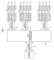
FIG. 1 a schematic diagram showing an illustrative embodiment of a robot controlling system. -
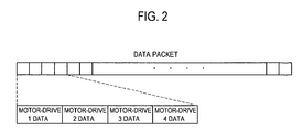
FIG. 2 is a schematic diagram showing a structure of a data packet. -
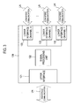
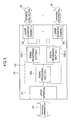
FIG. 3 is a schematic diagram showing a data transformation network board. -
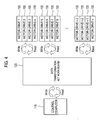
FIG. 4 is a schematic diagram showing data write and read operations. -
FIGS. 5 and6 are schematic diagrams showing examples of a robot control system. -
FIGS. 7 and8 are schematic diagrams showing examples of a data transformation network board. -
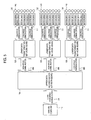
FIG. 1 is a schematic diagram showing an illustrative embodiment of a robot controlling system.FIG. 2 is a schematic diagram showing structure of a data packet. And,FIG. 3 is a schematic diagram showing a data transformation network board. - As shown in
FIG. 1 , the robot controlling system may include acontrol computer 110, a datatransformation network board 120, a plurality ofmotor drives 130 and a plurality ofmotors 140 coupled to the plurality of motor-drives 130. Thecontrol computer 110 and the datatransformation network board 120 communicate with each other by using a high speed communication UN. The high speed communication is ranged from 10Mbps to 1Gbps. The datatransformation network board 120 and the plurality ofmotor drives 130 communicate with each other using a low speed communication LN. The low speed communication is ranged from 1kbps to 10Mbps. - The
control computer 110 may send a control data packet to the datatransformation network board 120 and receive a response data packet from the datatransformation network board 120. Thecontrol computer 110 may be in communication with the datatransformation network board 120. The control data packet or the response data packet may be structured as illustrated inFIG. 2 . In one embodiment, the control data packet includes a control data MOTOR-DRIVE 1 DATA, MOTOR-DRIVE 2 DATA ... for controlling the plurality ofmotor drives 130, and the response data packet includes a plurality of response data MOTOR-DRIVE 1 DATA, MOTOR-DRIVE 2 DATA ..., which are received from the plurality of motor-drives 130. - Referring to
FIG. 3 , the datatransformation network board 120 may include anupper interface 121, asignal processing unit 122 and at least onelower interface 123. Theupper interface 121 is a unit for communicating with thecontrol computer 110. The at least onelower interface 123 is includes multiple channels for communication with the plurality ofmotor drives 130. Thecontrol computer 110 is in communication with the datatransformation network board 120 using the high-speed communication UN, and the plurality ofmotor drives 130 are connected to the datatransformation network board 120 using the low-speed communication LN. For example, the low-speed communication may include a controller area network (CAN) communication. The CAN communication is a serial bus network standard designed to allow devices, which are built in the robot controlling system, such as a sensor, a starter and a motor to communicate with each other. An address assignment technology, which is usually adopted in the Ethernet communication, is not used in the CAN communication. In the CAN communication, data is transmitted simultaneously to all nodes such as the devices built in the robot controlling system using a unique identifier. Each device may decide whether each device processes the data or not according to the unique identifier. The priority of data may be decided using a competition principle. It is possible to transmit the data without interruption in the CAN communication, which is different from the Ethernet communication. The CAN communication was designed specifically for automotive applications. Since the CAN communication is designed to have a series of sensors, it may be observed whether the automotive applications operate appropriately and safely. The CAN communication may be used in an open type communication system for an intelligent peripheral device and in an internal communication system for microcontrollers. The CAN communication may in some embodiments be standardized with ISO 11519 for maximum speed until 125 Kbps and standardized with ISO 19898 for maximum speed until 1 Mbps. The foregoing are only examples for configurations of the CAN communication and other configurations can also be used. - Referring back to
FIG. 1 , themotor drives 130 may in some embodiments be divided into a plurality of groups and the plurality of groups may be connected to the channels, so that the plurality of control data and the plurality of response data may be processed in parallel when the plurality ofmotor drives 130, which are connected to the datatransformation network board 120, are provided. The plurality of groups of themotor drives 130 may be determined by considering a control routine period, which may mean data transmission or reception (data communication) time. For example, assuming that N motor-drives 130 are installed and 1 ms is required for data transmission or reception between each of the N motor-drives 130 and the datatransformation network board 120, N ms may be required for data transmission or reception between all of the N motor-drives 130 and the datatransformation network board 120 if the N motor-drives 130 are not divided into multiple groups. But, when the N motor-drives 130 are equally divided into M groups, N/M ms may be required for communication. - Referring back to
FIG. 3 , thesignal processing unit 122 may include a memory (not shown) for storing the control data packet, which is transmitted from thecontrol computer 110, and the response data packet, which is transmitted from the plurality of motor-drives 130. Thesignal processing unit 122 may divide the control data packet into the control data in relation to the number of the multiple channels and transmit the control data to thecorresponding motor drives 130, which are included in each lower interface. Each of themotor drives 130 may form motor driving signals according to the control data, send the motor driving signals to themotors 140, and form the response data including operation results of themotors 140. Themotor drives 130 may transmit the response data to thesignal processing unit 122. Thesignal processing unit 122 may combine the plurality of response data received from the plurality ofmotor drives 130 to form the response data packet. Each of the control data may include motor drive identifications (IDs) for transmitting the control data to thecorresponding motor drives 130. The motor drive IDs may include information on the multiple channels of thelower interface 123 and information on themotor drives 130, which are connected to the multiple channels. The motor-drive IDs may be set by two digit numbers. The former digit number may be assigned for identification of the channels of thelower interface 123 and the latter digit number may be assigned for identification of themotor drives 130, which are connected to the channels of thelower interface 123. For example, when the motor drive ID is 23, the control data may be transmitted to thethird motor drive 130 of the second channel oflower interface 123. Thesignal processing unit 122 may include a DSP (digital signal processor) or FPGA (field programmable gate array). - Referring back to
FIG. 1 , each of the motor drives 130 may receive the control data from the datatransformation network board 120 and transmit the response data to the datatransformation network board 120. The plurality of motor drives 130 may control themotors 140, which are connected to the motor drives 130, respectively, according to the control data. The motor drives 130 may form the response data including the operation results of themotors 140, and so on. - In one embodiment as shown in
FIG. 4 , data write and read operations between thecontrol computer 110 and the datatransformation network board 120 may be performed by using high-speed communication. The data write and read operations between the datatransformation network board 120 and the plurality of motor drives 130 may be performed by using low-speed communication. Thecontrol computer 110 may combine the control data, when it is needed to perform the data write operation of the control data. Thecontrol computer 110 may not directly transmit the control data packet to the motor drives 130 but transmit the control data packet to the motor drives 130 via the datatransformation network board 120. The control data packet, which is transmitted to the datatransformation network board 120, is stored in the memory (not shown) of thesignal processing unit 122 as shown inFIG. 3 . The control data included in the control data packet may be transmitted to corresponding motor drives 130 through thelower interface 123 as shown inFIG. 3 at a predetermined period. The datatransformation network board 120 may read the response data of the motor drives 130 and store the response data in the memory of thesignal processing unit 122 at a predetermined period. The response data, which is stored in the memory of thesignal processing unit 122, are combined to form the response data packet as illustrated inFIG. 2 . Thecontrol computer 110 may perform the data read operation of the response data at a predetermined period. -
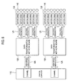
FIGS. 5 and6 are schematic diagrams showing examples of a robot control system. The data transformation network board of the robot control system may be in one embodiment hierarchically structured. For example, in the robot controlling system ofFIG. 5 , thecontrol computer 110 may transmit the control data packet to an upper datatransformation network board 150 for controlling a robot, and receive the response data packet from the upper datatransformation network board 150. The upper datatransformation network board 150 may divide the control data packet into intermediate control data packets to match the number of lower datatransformation network boards 120 and transmit the intermediate control data packets to the corresponding lower datatransformation network boards 120. The upper datatransformation network board 150 may receive intermediate response data packets from the lower datatransformation network boards 120 and combine the intermediate response data packets to form the response data packet. The lower datatransformation network boards 120 may divide the intermediate control data packets into control data, and transmit the control data to the corresponding motor drives 130. The lower datatransformation network boards 120 may combine the response data to form intermediate response data packets received from the motor-drives 130.FIG. 6 is a schematic diagram showing an example of a robot control system having two datatransformation network boards 120 in parallel. In the robot control system ofFIG. 6 , thecontrol computer 110 may form two control data packets and transmit each control data packet to the datatransformation network boards 120. Thecontrol computer 110 receives two response data packets from the datatransformation network boards 120. Each of the datatransformation network boards 120 may divide each control data packet into control data and transmit the control data to the corresponding motor drives 130. Each datatransformation network board 120 may receive the response data from the motor drives 130 and combine the response data to form the response data packets. -
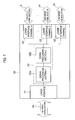
FIGS. 7 and8 are schematic diagrams showing examples of a data transformation network board. Thesignal processing unit 122 of the datatransformation network board 120 may be hierarchically structured. In the robot control system, thesignal processing unit 122 may include at least one signal processing section. Thesignal processing unit 122 of theFIG. 7 may include first and secondsignal processing sections upper interface 121 and the secondsignal processing section 122b may perform signal processing upon the data received or transmitted from/to thelower interface 123. Thesignal processing unit 122 of theFIG. 8 may include two second signal processing sections 122b_1, 122b_2, so that it becomes possible to decrease the load on thesignal processing unit 122 due to multiple channel connections to thelower interface 123. - Any reference in this specification to "one embodiment," "an embodiment," "example embodiment," "illustrative embodiment," etc. means that a particular feature, structure or characteristic described in connection with the embodiment is included in at least one embodiment of the present invention. The appearances of such phrases in various places in the specification are not necessarily all referring to the same embodiment. Further, when a particular feature, structure or characteristic is described in connection with any embodiment, it is submitted that it is within the purview of one skilled in the art to affect such feature, structure or characteristic in connection with other ones of the embodiments.
- Although embodiments have been described with reference to a number of illustrative embodiments thereof, it should be understood that numerous other modifications and embodiments can be devised by those skilled in the art that will fall within the spirit and scope of the principles of this disclosure. More particularly, numerous variations and modifications are possible in the component parts and/or arrangements of the subject combination arrangement within the scope of the disclosure, the drawings and the appended claims. In addition to variations and modifications in the component parts and/or arrangements, alternative uses will also be apparent to those skilled in the art.
Claims (13)
- A data transformation network apparatus comprising:an upper interface configured to communicate in first speed with a control computer to receive a control data packet from the control computer;a plurality of lower interfaces configured to communicate in second speed slower than the first speed with a plurality of motor drives; anda signal processing unit in communication with the upper interface and the plurality of lower interfaces, the signal processing unit being configured to divide the control data packet into a plurality of control data, and transmit the plurality of control data to the plurality of motor drives through the plurality of lower interfaces.
- The data transformation network apparatus of claim 1, wherein the plurality of lower interfaces are further configured to communicate with the plurality of motor drives to receive a plurality of response data from the plurality of motor drives, the signal processing unit is configured to combine the plurality of response data to form the response data packet, and the upper interface is further configured to transmit the response data packet to the control computer.
- The data transformation network apparatus of claim 2, wherein the signal processing unit is further configured to process the plurality of control data and the plurality of response data in parallel.
- The data transformation network apparatus of claim 3, wherein the plurality of control data include motor drive IDs for transmitting the plurality of control data to the plurality of corresponding motor drives.
- The data transformation network apparatus of claim 4, wherein the signal processing unit comprises;
a first signal processing section configured to divide the control data packet into the plurality of control data; and
at least one second signal processing section configured to transmit the plurality of control data to the corresponding motor drives through the plurality of lower interfaces. - The data transformation network apparatus of claim 5, wherein the at least one second signal processing section is further configured to combine the plurality of response data to form the response data packet; and the first signal processing section is further configured to transmit the response data packet to the control computer through the upper interface.
- A robot controlling system comprising;
a control computer;
a data transformation network apparatus of any one of claims 1 to 6 in communication with the control computer; and
a plurality of motor drives in communication with the data transformation network apparatus, the plurality of motor drives being configured to form driving signals for driving a plurality of motors according to the plurality of control data. - The robot controlling system of claim 7, wherein the plurality of motor drives are further configured to form the plurality of response data.
- A robot controlling method with a robot controlling system, the method comprising;
transmitting in first speed a control data packet containing a plurality of control data by a control computer within the robot controlling system;
dividing the transmitted control data packet into the plurality of control data by a data transformation network board within the robot controlling system; and
transmitting in second speed slower than the first speed the plurality of control data to a plurality of motor drives through a plurality of lower interfaces within the robot controlling system by the data transformation network board. - The robot controlling method of claim 9, the method further comprising:forming driving signals for driving a plurality of motors according to the plurality of control data by the motor drives.forming response data containing operation results of the plurality of motors according to the motor driving signals by the motor drives;combining the response data to form the response data packet by the data transformation network board; andtransmitting the response data packet to the control computer by the data transformation network board.
- The method of claim 10, wherein the control data includes motor drive IDs for transmitting of the control data to the plurality of corresponding motor drives.
- A computer readable medium comprising instructions that, when executed by a processor performs a method of controlling a robot, the method implemented in the computer readable medium comprising:receiving in first speed a control data packet containing a plurality of control data;dividing the received control data packet into the plurality of control data; andtransmitting in second speed slower than the first speed the plurality of control data to a plurality of motor drives.
- The computer readable medium of claim 12 further comprising:forming driving signals for driving a plurality of motors according to the control data;forming response data containing operation results of the plurality of motors according to the motor driving signals;combining the response data to form the response data packet; andtransmitting the response data packet to a control computer.
Applications Claiming Priority (1)
| Application Number | Priority Date | Filing Date | Title |
|---|---|---|---|
| KR1020090024449A KR101041375B1 (en) | 2009-03-23 | 2009-03-23 | Network transformation-apparatus, system and method for controlling robot using the same |
Publications (2)
| Publication Number | Publication Date |
|---|---|
| EP2233255A2 true EP2233255A2 (en) | 2010-09-29 |
| EP2233255A3 EP2233255A3 (en) | 2011-11-30 |
Family
ID=42046464
Family Applications (1)
| Application Number | Title | Priority Date | Filing Date |
|---|---|---|---|
| EP09011451A Ceased EP2233255A3 (en) | 2009-03-23 | 2009-09-07 | Data transformation network apparatus and robot controlling system and method using the same |
Country Status (2)
| Country | Link |
|---|---|
| EP (1) | EP2233255A3 (en) |
| KR (1) | KR101041375B1 (en) |
Cited By (2)
| Publication number | Priority date | Publication date | Assignee | Title |
|---|---|---|---|---|
| WO2019055125A1 (en) | 2017-09-18 | 2019-03-21 | Verb Surgical Inc. | Robotic surgical system having a communication network of a ring topology and method for use therewith |
| US11266474B2 (en) | 2017-09-18 | 2022-03-08 | Verb Surgical Inc. | Robotic surgical system and method for communicating synchronous and asynchronous information to and from nodes of a robotic arm |
Families Citing this family (6)
| Publication number | Priority date | Publication date | Assignee | Title |
|---|---|---|---|---|
| KR101229911B1 (en) * | 2011-05-24 | 2013-02-05 | 주식회사 서보산전 | Method for communication between upper controller for controlling movement of robot arm and main controller for driving many articulations of robot arm |
| KR101343607B1 (en) | 2011-11-17 | 2014-01-16 | 재단법인대구경북과학기술원 | System and Method for compensating Packet loss of Wireless motor controller |
| KR101563735B1 (en) | 2013-12-24 | 2015-11-09 | 전자부품연구원 | System and method for changing wpan network channel responding to wireless environment change |
| CN105234937B (en) * | 2015-10-13 | 2017-12-22 | 宁波中创焊接技术有限公司 | General Mobile chassis control system |
| KR101977404B1 (en) * | 2017-03-21 | 2019-05-13 | 엘에스산전 주식회사 | High voltage direct current transmission system |
| CN112171656B (en) * | 2019-07-04 | 2022-06-10 | 深圳市越疆科技有限公司 | Control method and device of mechanical arm and server |
Citations (3)
| Publication number | Priority date | Publication date | Assignee | Title |
|---|---|---|---|---|
| US20040008738A1 (en) * | 2002-03-18 | 2004-01-15 | Masaki Fukuchi | Image transmission device and method, transmitting device and method, receiving device and method, and robot apparatus |
| US20040249651A1 (en) * | 2001-08-07 | 2004-12-09 | Detlef Fischer | Method and process management system for the operation of a technical plant |
| KR100758289B1 (en) | 2006-05-15 | 2007-09-12 | 주식회사 윌링스 | Robot control system using high speed network and control method thereof |
Family Cites Families (1)
| Publication number | Priority date | Publication date | Assignee | Title |
|---|---|---|---|---|
| KR100901704B1 (en) * | 2007-08-16 | 2009-06-08 | 한국전자통신연구원 | Apparatus for transmitting and receiving high-speed signals having various volumes |
-
2009
- 2009-03-23 KR KR1020090024449A patent/KR101041375B1/en active IP Right Grant
- 2009-09-07 EP EP09011451A patent/EP2233255A3/en not_active Ceased
Patent Citations (3)
| Publication number | Priority date | Publication date | Assignee | Title |
|---|---|---|---|---|
| US20040249651A1 (en) * | 2001-08-07 | 2004-12-09 | Detlef Fischer | Method and process management system for the operation of a technical plant |
| US20040008738A1 (en) * | 2002-03-18 | 2004-01-15 | Masaki Fukuchi | Image transmission device and method, transmitting device and method, receiving device and method, and robot apparatus |
| KR100758289B1 (en) | 2006-05-15 | 2007-09-12 | 주식회사 윌링스 | Robot control system using high speed network and control method thereof |
Non-Patent Citations (2)
| Title |
|---|
| KAYNOV D ET AL: "Industrial automation based approach to design control system of the humanoid robot", INDUSTRIAL ELECTRONICS, 2007. ISIE 2007. IEEE INTERNATIONAL SYMPOSIUM ON, IEEE, PI, 1 June 2007 (2007-06-01), pages 2179 - 2184, XP031156482, ISBN: 978-1-4244-0754-5 * |
| KRISTIAN REGENSTEIN ET AL: "Design of an open hardware architecture for the humanoid robot ARMAR", 1 October 2003 (2003-10-01), XP055554571, Retrieved from the Internet <URL:https://www.researchgate.net/profile/Ruediger_Dillmann/publication/228872320_Design_of_an_open_hardware_architecture_for_the_humanoid_robot_ARMAR/links/0c96051b8d829b4f99000000/Design-of-an-open-hardware-architecture-for-the-humanoid-robot-ARMAR.pdf> [retrieved on 20190211] * |
Cited By (6)
| Publication number | Priority date | Publication date | Assignee | Title |
|---|---|---|---|---|
| WO2019055125A1 (en) | 2017-09-18 | 2019-03-21 | Verb Surgical Inc. | Robotic surgical system having a communication network of a ring topology and method for use therewith |
| CN111093910A (en) * | 2017-09-18 | 2020-05-01 | 沃博手术股份有限公司 | Robotic surgical system with ring topology communication network and method of use thereof |
| EP3684561A4 (en) * | 2017-09-18 | 2021-06-16 | Verb Surgical Inc. | Robotic surgical system having a communication network of a ring topology and method for use therewith |
| US11266474B2 (en) | 2017-09-18 | 2022-03-08 | Verb Surgical Inc. | Robotic surgical system and method for communicating synchronous and asynchronous information to and from nodes of a robotic arm |
| US11419690B2 (en) | 2017-09-18 | 2022-08-23 | Verb Surgical Inc. | Robotic surgical system having a communication network of a ring topology and method for use therewith |
| CN111093910B (en) * | 2017-09-18 | 2023-09-01 | 威博外科公司 | Robotic surgical system with ring topology communication network and method of use thereof |
Also Published As
| Publication number | Publication date |
|---|---|
| EP2233255A3 (en) | 2011-11-30 |
| KR20100106030A (en) | 2010-10-01 |
| KR101041375B1 (en) | 2011-06-15 |
Similar Documents
| Publication | Publication Date | Title |
|---|---|---|
| EP2233255A2 (en) | Data transformation network apparatus and robot controlling system and method using the same | |
| CN111937352B (en) | Method, device, interface and storage medium for transmitting data via a communication channel | |
| CN100496048C (en) | Multi-host communication system | |
| EP0459753A2 (en) | Network access controller having logical FIFO buffer | |
| US20100211190A1 (en) | Control system, control method, master device, and control device | |
| WO2002015404A2 (en) | Programmable auto-converting analog to digital conversion module | |
| WO2002015473A2 (en) | In circuit serial programming of default configuration | |
| JP3882666B2 (en) | Transmission device and electronic control device | |
| US11233736B2 (en) | Vehicle gateway and method of controlling the same | |
| JP2006244489A (en) | Modular numerical control | |
| CN104144094A (en) | Method for operating slave node of digital bus system | |
| CN109582616A (en) | Communication system and method based on universal serial bus | |
| US10848419B2 (en) | Data transmission method, communication network and master participant | |
| US9715471B2 (en) | Master bus device for a vehicle communication bus of a motor vehicle | |
| JP2004088208A (en) | Data transmission system and method therefor | |
| US10899362B2 (en) | Communication apparatus and communication system | |
| CN108762146B (en) | Low-delay synchronous internal networking motion control system of stepping motor | |
| KR100916665B1 (en) | Air-conditioner and operating method thereof | |
| US10935959B2 (en) | Motor control device, control system, and motor control method | |
| JPWO2013183140A1 (en) | Motion controller device and communication method in the same device | |
| KR20040015186A (en) | Systems and methods for assigning an address to a network device added to an existing network | |
| CN111343069A (en) | Distributed control communication bus based on robot sensing system and robot | |
| CN205051614U (en) | Step motor drive arrangement and step motor control system | |
| JP4708901B2 (en) | Data processing module and method for preparing message transmission | |
| US11969890B2 (en) | Control method and control system using the same |
Legal Events
| Date | Code | Title | Description |
|---|---|---|---|
| PUAI | Public reference made under article 153(3) epc to a published international application that has entered the european phase |
Free format text: ORIGINAL CODE: 0009012 |
|
| AK | Designated contracting states |
Kind code of ref document: A2 Designated state(s): AT BE BG CH CY CZ DE DK EE ES FI FR GB GR HR HU IE IS IT LI LT LU LV MC MK MT NL NO PL PT RO SE SI SK SM TR |
|
| AX | Request for extension of the european patent |
Extension state: AL BA RS |
|
| 17P | Request for examination filed |
Effective date: 20110825 |
|
| PUAL | Search report despatched |
Free format text: ORIGINAL CODE: 0009013 |
|
| AK | Designated contracting states |
Kind code of ref document: A3 Designated state(s): AT BE BG CH CY CZ DE DK EE ES FI FR GB GR HR HU IE IS IT LI LT LU LV MC MK MT NL NO PL PT RO SE SI SK SM TR |
|
| AX | Request for extension of the european patent |
Extension state: AL BA RS |
|
| RIC1 | Information provided on ipc code assigned before grant |
Ipc: B25J 9/16 20060101AFI20111027BHEP Ipc: G05B 19/414 20060101ALI20111027BHEP Ipc: H02P 5/74 20060101ALI20111027BHEP |
|
| RAP1 | Party data changed (applicant data changed or rights of an application transferred) |
Owner name: KOREA INSTITUTE OF SCIENCE AND TECHNOLOGY |
|
| STAA | Information on the status of an ep patent application or granted ep patent |
Free format text: STATUS: EXAMINATION IS IN PROGRESS |
|
| 17Q | First examination report despatched |
Effective date: 20170420 |
|
| STAA | Information on the status of an ep patent application or granted ep patent |
Free format text: STATUS: THE APPLICATION HAS BEEN REFUSED |
|
| 18R | Application refused |
Effective date: 20200610 |