EP2232667B1 - Verfahren und system zur steuerung von windenergieanlagen - Google Patents
Verfahren und system zur steuerung von windenergieanlagen Download PDFInfo
- Publication number
- EP2232667B1 EP2232667B1 EP08864798A EP08864798A EP2232667B1 EP 2232667 B1 EP2232667 B1 EP 2232667B1 EP 08864798 A EP08864798 A EP 08864798A EP 08864798 A EP08864798 A EP 08864798A EP 2232667 B1 EP2232667 B1 EP 2232667B1
- Authority
- EP
- European Patent Office
- Prior art keywords
- wind
- grid
- rpm
- frequency
- wind turbine
- Prior art date
- Legal status (The legal status is an assumption and is not a legal conclusion. Google has not performed a legal analysis and makes no representation as to the accuracy of the status listed.)
- Not-in-force
Links
Images


Classifications
-
- F—MECHANICAL ENGINEERING; LIGHTING; HEATING; WEAPONS; BLASTING
- F03—MACHINES OR ENGINES FOR LIQUIDS; WIND, SPRING, OR WEIGHT MOTORS; PRODUCING MECHANICAL POWER OR A REACTIVE PROPULSIVE THRUST, NOT OTHERWISE PROVIDED FOR
- F03D—WIND MOTORS
- F03D9/00—Adaptations of wind motors for special use; Combinations of wind motors with apparatus driven thereby; Wind motors specially adapted for installation in particular locations
- F03D9/20—Wind motors characterised by the driven apparatus
- F03D9/25—Wind motors characterised by the driven apparatus the apparatus being an electrical generator
- F03D9/255—Wind motors characterised by the driven apparatus the apparatus being an electrical generator connected to electrical distribution networks; Arrangements therefor
-
- F—MECHANICAL ENGINEERING; LIGHTING; HEATING; WEAPONS; BLASTING
- F03—MACHINES OR ENGINES FOR LIQUIDS; WIND, SPRING, OR WEIGHT MOTORS; PRODUCING MECHANICAL POWER OR A REACTIVE PROPULSIVE THRUST, NOT OTHERWISE PROVIDED FOR
- F03D—WIND MOTORS
- F03D13/00—Assembly, mounting or commissioning of wind motors; Arrangements specially adapted for transporting wind motor components
- F03D13/20—Arrangements for mounting or supporting wind motors; Masts or towers for wind motors
- F03D13/25—Arrangements for mounting or supporting wind motors; Masts or towers for wind motors specially adapted for offshore installation
-
- F—MECHANICAL ENGINEERING; LIGHTING; HEATING; WEAPONS; BLASTING
- F03—MACHINES OR ENGINES FOR LIQUIDS; WIND, SPRING, OR WEIGHT MOTORS; PRODUCING MECHANICAL POWER OR A REACTIVE PROPULSIVE THRUST, NOT OTHERWISE PROVIDED FOR
- F03D—WIND MOTORS
- F03D9/00—Adaptations of wind motors for special use; Combinations of wind motors with apparatus driven thereby; Wind motors specially adapted for installation in particular locations
- F03D9/20—Wind motors characterised by the driven apparatus
- F03D9/25—Wind motors characterised by the driven apparatus the apparatus being an electrical generator
- F03D9/255—Wind motors characterised by the driven apparatus the apparatus being an electrical generator connected to electrical distribution networks; Arrangements therefor
- F03D9/257—Wind motors characterised by the driven apparatus the apparatus being an electrical generator connected to electrical distribution networks; Arrangements therefor the wind motor being part of a wind farm
-
- H—ELECTRICITY
- H02—GENERATION; CONVERSION OR DISTRIBUTION OF ELECTRIC POWER
- H02J—ELECTRIC POWER NETWORKS; CIRCUIT ARRANGEMENTS OR SYSTEMS FOR SUPPLYING OR DISTRIBUTING ELECTRIC POWER; SYSTEMS FOR STORING ELECTRIC ENERGY
- H02J3/00—Circuit arrangements for AC mains or AC distribution networks
- H02J3/38—Arrangements for feeding a single network from two or more generators or sources in parallel; Arrangements for feeding already energised networks from additional generators or sources in parallel
- H02J3/381—Dispersed generators
-
- H—ELECTRICITY
- H02—GENERATION; CONVERSION OR DISTRIBUTION OF ELECTRIC POWER
- H02J—ELECTRIC POWER NETWORKS; CIRCUIT ARRANGEMENTS OR SYSTEMS FOR SUPPLYING OR DISTRIBUTING ELECTRIC POWER; SYSTEMS FOR STORING ELECTRIC ENERGY
- H02J3/00—Circuit arrangements for AC mains or AC distribution networks
- H02J3/38—Arrangements for feeding a single network from two or more generators or sources in parallel; Arrangements for feeding already energised networks from additional generators or sources in parallel
- H02J3/46—Controlling the sharing of generated power between the generators, sources or networks
-
- F—MECHANICAL ENGINEERING; LIGHTING; HEATING; WEAPONS; BLASTING
- F05—INDEXING SCHEMES RELATING TO ENGINES OR PUMPS IN VARIOUS SUBCLASSES OF CLASSES F01-F04
- F05B—INDEXING SCHEME RELATING TO WIND, SPRING, WEIGHT, INERTIA OR LIKE MOTORS, TO MACHINES OR ENGINES FOR LIQUIDS COVERED BY SUBCLASSES F03B, F03D AND F03G
- F05B2220/00—Application
- F05B2220/70—Application in combination with
- F05B2220/706—Application in combination with an electrical generator
- F05B2220/7064—Application in combination with an electrical generator of the alternating current (A.C.) type
- F05B2220/70644—Application in combination with an electrical generator of the alternating current (A.C.) type of the asynchronous type, i.e. induction type
-
- F—MECHANICAL ENGINEERING; LIGHTING; HEATING; WEAPONS; BLASTING
- F05—INDEXING SCHEMES RELATING TO ENGINES OR PUMPS IN VARIOUS SUBCLASSES OF CLASSES F01-F04
- F05B—INDEXING SCHEME RELATING TO WIND, SPRING, WEIGHT, INERTIA OR LIKE MOTORS, TO MACHINES OR ENGINES FOR LIQUIDS COVERED BY SUBCLASSES F03B, F03D AND F03G
- F05B2240/00—Components
- F05B2240/90—Mounting on supporting structures or systems
- F05B2240/95—Mounting on supporting structures or systems offshore
-
- F—MECHANICAL ENGINEERING; LIGHTING; HEATING; WEAPONS; BLASTING
- F05—INDEXING SCHEMES RELATING TO ENGINES OR PUMPS IN VARIOUS SUBCLASSES OF CLASSES F01-F04
- F05B—INDEXING SCHEME RELATING TO WIND, SPRING, WEIGHT, INERTIA OR LIKE MOTORS, TO MACHINES OR ENGINES FOR LIQUIDS COVERED BY SUBCLASSES F03B, F03D AND F03G
- F05B2240/00—Components
- F05B2240/90—Mounting on supporting structures or systems
- F05B2240/96—Mounting on supporting structures or systems as part of a wind turbine farm
-
- F—MECHANICAL ENGINEERING; LIGHTING; HEATING; WEAPONS; BLASTING
- F05—INDEXING SCHEMES RELATING TO ENGINES OR PUMPS IN VARIOUS SUBCLASSES OF CLASSES F01-F04
- F05B—INDEXING SCHEME RELATING TO WIND, SPRING, WEIGHT, INERTIA OR LIKE MOTORS, TO MACHINES OR ENGINES FOR LIQUIDS COVERED BY SUBCLASSES F03B, F03D AND F03G
- F05B2270/00—Control
- F05B2270/10—Purpose of the control system
- F05B2270/104—Purpose of the control system to match engine to driven device
- F05B2270/1041—Purpose of the control system to match engine to driven device in particular the electrical frequency of driven generator
-
- H—ELECTRICITY
- H02—GENERATION; CONVERSION OR DISTRIBUTION OF ELECTRIC POWER
- H02J—ELECTRIC POWER NETWORKS; CIRCUIT ARRANGEMENTS OR SYSTEMS FOR SUPPLYING OR DISTRIBUTING ELECTRIC POWER; SYSTEMS FOR STORING ELECTRIC ENERGY
- H02J2101/00—Supply or distribution of decentralised, dispersed or local electric power generation
- H02J2101/20—Dispersed power generation using renewable energy sources
- H02J2101/28—Wind energy
-
- H—ELECTRICITY
- H02—GENERATION; CONVERSION OR DISTRIBUTION OF ELECTRIC POWER
- H02J—ELECTRIC POWER NETWORKS; CIRCUIT ARRANGEMENTS OR SYSTEMS FOR SUPPLYING OR DISTRIBUTING ELECTRIC POWER; SYSTEMS FOR STORING ELECTRIC ENERGY
- H02J3/00—Circuit arrangements for AC mains or AC distribution networks
- H02J3/36—Arrangements for transfer of electric power between AC networks via high-voltage DC [HVDC] links; Arrangements for transfer of electric power between generators and networks via HVDC links
-
- Y—GENERAL TAGGING OF NEW TECHNOLOGICAL DEVELOPMENTS; GENERAL TAGGING OF CROSS-SECTIONAL TECHNOLOGIES SPANNING OVER SEVERAL SECTIONS OF THE IPC; TECHNICAL SUBJECTS COVERED BY FORMER USPC CROSS-REFERENCE ART COLLECTIONS [XRACs] AND DIGESTS
- Y02—TECHNOLOGIES OR APPLICATIONS FOR MITIGATION OR ADAPTATION AGAINST CLIMATE CHANGE
- Y02E—REDUCTION OF GREENHOUSE GAS [GHG] EMISSIONS, RELATED TO ENERGY GENERATION, TRANSMISSION OR DISTRIBUTION
- Y02E10/00—Energy generation through renewable energy sources
- Y02E10/70—Wind energy
- Y02E10/72—Wind turbines with rotation axis in wind direction
-
- Y—GENERAL TAGGING OF NEW TECHNOLOGICAL DEVELOPMENTS; GENERAL TAGGING OF CROSS-SECTIONAL TECHNOLOGIES SPANNING OVER SEVERAL SECTIONS OF THE IPC; TECHNICAL SUBJECTS COVERED BY FORMER USPC CROSS-REFERENCE ART COLLECTIONS [XRACs] AND DIGESTS
- Y02—TECHNOLOGIES OR APPLICATIONS FOR MITIGATION OR ADAPTATION AGAINST CLIMATE CHANGE
- Y02E—REDUCTION OF GREENHOUSE GAS [GHG] EMISSIONS, RELATED TO ENERGY GENERATION, TRANSMISSION OR DISTRIBUTION
- Y02E10/00—Energy generation through renewable energy sources
- Y02E10/70—Wind energy
- Y02E10/727—Offshore wind turbines
-
- Y—GENERAL TAGGING OF NEW TECHNOLOGICAL DEVELOPMENTS; GENERAL TAGGING OF CROSS-SECTIONAL TECHNOLOGIES SPANNING OVER SEVERAL SECTIONS OF THE IPC; TECHNICAL SUBJECTS COVERED BY FORMER USPC CROSS-REFERENCE ART COLLECTIONS [XRACs] AND DIGESTS
- Y02—TECHNOLOGIES OR APPLICATIONS FOR MITIGATION OR ADAPTATION AGAINST CLIMATE CHANGE
- Y02E—REDUCTION OF GREENHOUSE GAS [GHG] EMISSIONS, RELATED TO ENERGY GENERATION, TRANSMISSION OR DISTRIBUTION
- Y02E10/00—Energy generation through renewable energy sources
- Y02E10/70—Wind energy
- Y02E10/76—Power conversion electric or electronic aspects
-
- Y—GENERAL TAGGING OF NEW TECHNOLOGICAL DEVELOPMENTS; GENERAL TAGGING OF CROSS-SECTIONAL TECHNOLOGIES SPANNING OVER SEVERAL SECTIONS OF THE IPC; TECHNICAL SUBJECTS COVERED BY FORMER USPC CROSS-REFERENCE ART COLLECTIONS [XRACs] AND DIGESTS
- Y02—TECHNOLOGIES OR APPLICATIONS FOR MITIGATION OR ADAPTATION AGAINST CLIMATE CHANGE
- Y02E—REDUCTION OF GREENHOUSE GAS [GHG] EMISSIONS, RELATED TO ENERGY GENERATION, TRANSMISSION OR DISTRIBUTION
- Y02E60/00—Enabling technologies; Technologies with a potential or indirect contribution to GHG emissions mitigation
- Y02E60/60—Arrangements for transfer of electric power between AC networks or generators via a high voltage DC link [HVCD]
-
- Y—GENERAL TAGGING OF NEW TECHNOLOGICAL DEVELOPMENTS; GENERAL TAGGING OF CROSS-SECTIONAL TECHNOLOGIES SPANNING OVER SEVERAL SECTIONS OF THE IPC; TECHNICAL SUBJECTS COVERED BY FORMER USPC CROSS-REFERENCE ART COLLECTIONS [XRACs] AND DIGESTS
- Y02—TECHNOLOGIES OR APPLICATIONS FOR MITIGATION OR ADAPTATION AGAINST CLIMATE CHANGE
- Y02P—CLIMATE CHANGE MITIGATION TECHNOLOGIES IN THE PRODUCTION OR PROCESSING OF GOODS
- Y02P80/00—Climate change mitigation technologies for sector-wide applications
- Y02P80/10—Efficient use of energy, e.g. using compressed air or pressurized fluid as energy carrier
Definitions
- the present invention generally relates to a method, a system and a computer program product for achieving optimal power production by enhancing and controlling the electric power production in a wind farm/plant.
- the invention concerns enhanced control and optimization of production in a group of wind turbine generators (WTGs) consisting of at least two wind turbine driven generators of asynchronous fixed speed generator type, connected to an AC grid (WTG grid) by the principle of an electrical torsion shaft, and which grid frequency is controllable through a grid controller device.
- WTGs wind turbine generators
- the invention further relates to a computer program and a computer readable medium comprising instructions for bringing a computer to perform said method.
- Wind Turbine Generator or Wind Turbine Generators (WTGs) is the description of complete wind turbine, including structure, individual or in multiples.
- Control Device is the invention by this application and may also be referred to as Supervisory Control Module (CD).
- GCD Grid Control Device controls the HVDC grid system. This unit is connected to or integrated with the grid system.
- Grid Code describes conditions and minimum requirements which need to be met in order for a power generation plant to be connected to the utility Public grid. For example, requirement for low voltage ride through function, if the utility Public grid voltage drops down to a certain level for a given amount of time, means that the wind turbine has to be in operation during and direct after such described grid disturbance.
- the grid code also describes minimum requirements for consumption of reactive and other power functions, required by power plants of today. More details of this can be found in specific documents issued by E.ON, Vattenfall etc. We refer to document by Risoe, Denmark which has summarized various grid code requirements (Ris ⁇ -R-1617(EN)).
- HVDC system or HVDC Light or HVDC Plus system (referred to as HVDC Light system) is a DC transmission system available on the market today. It is a based on a voltage source converter (VSC) technology which has characteristics suitable for connecting large amounts of wind power to Public grids, even at weak points in a Public grid system and without having to improve the short-circuit power ratio.
- VSC voltage source converter
- This HVDC Light system does not require any additional compensation, as this is inherent in the control of the converters. From operation of installed systems experience has been gained with HVDC Light transmission systems showing it is an excellent tool for bringing power from windmill parks to a Public grid and at the same time contribute to AC voltage stabilization.
- An HVDC Light transmission system is able to control the active power transmission in an exact way. The power transmission can be combined with a frequency controller that varies the grid frequency.
- An HVDC Light converter also controls reactive power for its AC bus, in conjunction with a master controller.
- the master controller can be designed from any new algorithm.
- the HVDC Light transmission system can provide control functions for active and reactive power, so that both voltage and frequency can be controlled from the converter station. In particular, this allows black starting by controlling the voltage and frequency from zero to nominal.
- HVDC Light connected to a wind farm could also give the possibility to provide reactive power to the windmills during the start up. How the frequency and voltage are controlled is set by the wind farm requirements.
- An HVDC Light transmission has only one significant value connecting both grids with each other being; the real power in size and direction which is equivalent to the product U x I on the DC link. All the other physical values, which are typical for an AC grid (reactive power, apparent power, frequency, harmonics, DIPS, SAGS, flicker etc.) are decoupled and do not affect the other grid. Many of these values can be controlled and mitigated by intelligent control schemes from the converter feeding the respective grid. Each converter is controllable through set-points given to the converter controller, such set-points can be provided through Ethernet access and in protocols provided by the supplier of such grid system.
- WTG grid is the AC power cable system that connects each wind turbine to the offshore substation or Offshore HVDC station.
- AC Transmission grid is the high voltage AC cable system that connects the offshore substation with the onshore substation.
- DC Transmission grid is the high voltage DC cable system that connect the offshore HVDC station with the onshore HVDC station.
- Onshore substation is the connection point where AC transmission grid is connected and where the connection is to the Public grid.
- Onshore HVDC station is the onshore station that connects the DC transmission grid to the AC Public grid.
- Offshore substation is the connection point offshore where the wind farm grid connects to the AC transmission grid.
- Offshore HVDC station is the connection point offshore where the wind farm grid connects to the DC transmission grid.
- Public grid is the AC high voltage grid system that distributes power for consumption within an area, region or country.
- Wind turbine technology today uses individual configurations of converter technology installed in each and every wind turbine tower which makes the WTG more complex and more expensive. Future wind power plants will also be located further away from grid connection points, and it is then needed to reinforce electrical grid structure and this impacts on the electrical grid system to which these power plants will supply its power and will add further costs to the project. This is especially evident in offshore wind power projects where the wind farms will be very large, more than 300 MW, and where the distance to shore is much longer, maybe exceeding 100 km in some projects. Subsequently, the use of conventional AC grid solutions is no longer feasible and DC systems become a better option due to lower transmission cable losses and thinner cables. Here big companies are active and the first grid systems of this kind already have been found as the best option for use with wind farms in recent procurements. This counts for both onshore and offshore wind farms.
- the size of the wind turbines installed during this period in general was between 50 - 200 kW per unit, and a great number of machines were installed on an individual basis. Groups of these machines (wind farms), where installed in greater numbers in the USA.
- Another benefit of this system is that power production from a wind turbine with variable speed can be increased by reducing rpm in partial load conditions. This increase may range from 4-5% in a low wind speed site and down to 1-1,5% for an offshore high wind speed site.
- the benefit is gained in low wind conditions as the aero dynamical efficiency of the wind turbine rotor increases if the rotor rpm can be reduced in low wind. This is all performed by the individual wind turbine controller and by equipment located in each wind turbine (special generator, converter and related equipment).
- the system described means that the grid code can now be achieved without capacitor banks, SVC stations and other expensive equipment otherwise needed.
- the system also brings flexibility in the driveline and the variable speed enables avoidance of resonance in structures.
- Each wind turbine now is an individual power plant that deals with individual grid issues and adaption to wind variation and variable speed increases production with up to 5% (low wind site), making it defendable to implement as added costs are lower than the performance benefit.
- the patent EP1252441 (Siemens) describes a wind rotor group comprising asynchronous squirrel-cage alternators (generators) operating at a mutually common frequency, which can change in a sliding form. It also states that this group of generators can be connected to a direct-current transmission system, and can be connected via a mutually common converter. This patent does not describe the important features for how the frequency is set at a certain level and what logic is used to choose a particular set-point for the frequency. In other words, the patent only describes a physical (electrical) lay-out of multiple wind turbines but doesn't disclose in what way it can be realized.
- the present invention performs specific tasks based on a number of inputs.
- the design difference to the present invention is that the control device is a central control unit that can monitor many variables in the turbines, the environment and in the grid, and that can calculate optimum settings in order to manage for example loads, power production, vibrations/resonance, etc and send signals to the turbines and the grid in order to change necessary set-points.
- the patent US6479907 discloses a plant for generating electric power through at least two separately driven wind power generators.
- the generators are feeding an alternating voltage to an alternating voltage line in common and a converter is adapted to convert the alternating voltage into direct voltage.
- a unit is adapted to control the converter to a frequency in such a way that a power maximum is obtained.
- the total power generated and fed to the converter is determined by measuring the current and voltage in the grid.
- the Siemens patent describes the principle for achieving collective variable rpm at wind turbines. However, there are important differences in the logic and process for achieving this function where the patent does not measure/collect parameter values/data individually from the wind power generators to establish the necessary change resulting in less effective control.
- the present invention uses individual WTG data as basis for optimization of grid frequency and power production.
- the present inventions control device is applicable and very flexible for a wide range of production situations.
- both grids local and public
- the design difference is that this patent deploys converter technology in parallel to the main connection cable, whereas in the present invention the main line includes the converter technology - i.e. not in a parallel set-up.
- the patent document WO01/77524 (Aerodyn Engineering), "Method for operating offshore wind turbine plants based on the frequency of their towers” relates to a method for operating a wind turbine plant which is provided with a device for regulating the speed of the rotor.
- This method comprises determination of the critical frequency of the respective turbine and/or turbine components, determination of the speed range of the rotor, in which the entire turbine and/or individual turbine components is/are excited in the vicinity of their critical frequencies and operation of the wind turbine plant only below and above the critical speed range, the latter being traversed rapidly.
- each wind turbine has to contain a control module, including measurement and signal processing equipment.
- the document also states that each wind turbine has a rotor speed regulating device.
- the present invention comprises multiple wind turbines all having the same/similar natural frequency that needs to be avoided during power production, and that the rapid traversing through this frequency takes place collectively and is controlled by a central control device.
- the design difference is that in the present invention none of the turbines needs its own control unit, but that the frequency avoidance functions are performed centrally in one control unit.
- none of the wind turbines has a rotor speed regulating device as the rotor speed will be controlled/changed by adjusting the frequency in the WTG grid at which the squirrel-cage asynchronous generators will operate.
- the invention according to WO03/030329 (Wobben) relates to a method for operating a wind park, consisting of several wind power plants.
- the wind park is connected to an electric supply network into which the power produced by the wind park is fed and the wind park and/or at least one of the wind power plants of the wind park, is provided with a control signal/input which is used to adjust the electric power of the wind park or one or several individual wind plants within a range of 0-100% of the respectively provided power, especially the nominal output thereof.
- a data processing device is connected to the control input and is used to adjust the control value within a range of 0-100% related to the amount of power available from the entire wind park at the output where it is fed into the power network.
- the operator (EVU) of the electric power supply network to which the wind park is connected can adjust the power provided by the wind park via the control input.
- the patent describes that a number of input value are measured, which then lead to a control of the wind turbines.
- This prior art specifically mentions that the wind park is connected to a power supply network and that the data processing apparatus can set the power delivered to the network. This will be done by the operator of the power supply network.
- the application is that at least one or more wind power installations (or all wind power installations of the wind park) are throttled when the maximum possible network feed-in power value is reached.
- the present invention is able to set more parameters compared to just the delivered power. These parameters do not only apply to the wind turbines but to the grid as well.
- the present concept also anticipates that it can be connected to transmission networks, not just to distribution networks.
- each wind turbine contains a microprocessor, which has full control over all the turbine parameters and which receives a power level set point as input from the data processing apparatus.
- most of the control functions will not be handled in each turbine, but will be done centrally by the CD.
- the CD communicates to turbines through electrical set-points like the grid frequency.
- the present invention not only controls the wind turbines, based on a number of measured input values, but also controls important grid parameters as well.
- the invention WO04/099604 (Wobben), "Operating method for a wind park”, relates to an operating method for a wind park consisting of a plurality of wind energy plants where a wind plant is provided with an electric generator and a wind park provided with a central device for controlling the wind park.
- the aim of said invention is to develop a method for operating the wind park consisting of a plurality of wind energy plants, a wind plant provided with an electric generator and a wind park provided with a central device for controlling the wind park, wherein the executions of operating processes are carried out by a limited and even reduced power supplied from the net (reference power).
- the inventive operating method for a wind park consisting of a plurality of wind energy plants is characterised in that the operating processes of each wind energy plant are controlled in such a way that the net electrical power is supplied up to a predefined maximum value.
- This patent specifically mentions that operational procedures are controlled in such a way that electrical power is taken from an electrical network only up to a pre-determinable maximum value. In other words, power consumption is the controlling feature.
- the drawback is that each wind turbine will contain a costly unit that has full control over all the turbine parameters.
- the present invention system uses the local grid frequency as the controlling parameter.
- the difference is that the prior art patent implies that each wind turbine contains a microprocessor, which has full control over all the turbine parameters and which receives a power level set point as input from the data processing apparatus.
- most of the control functions will not be handled in each turbine, but will be done centrally by the Supervisory Control Module.
- the CD communicates to turbines through electrical set-points like the grid frequency.
- the present invention includes as an important feature the functions to control WTG rpm through the grid.
- the design difference is therefore an added interface to control grid parameters.
- Another aspect is that with the present invention a number of functions can be achieved without sending signals to the wind turbine control interface, but sending signals to the grid control interface through which grid frequency can be adjusted which will directly impact the rpm of the wind turbine rotor.
- the present invention uses local grid frequency as a controlling parameter for WTG rpm.
- the invention relates to a method, a system and a computer program product for controlling the operations of a wind farm, for achieving optimal power production, comprising at least two wind turbine generators of asynchronous fixed speed generator type each connected, when in use, to a frequency controlled AC grid by the principle of an electrical torsion shaft, direct coupled to an HVDC-system.
- the present invention is a new way of approaching the control of a wind farm in form of a multi-task (or "power plant") control, and will cut investment costs, increase project performance and economics, decrease project failures/downtime by elimination of sensitive equipment and reduction of the number of components used as well as reduction of cable terminations.
- the present invention makes use of a known HVDC system as a transmission link to public grid connection point.
- the control device works as an interpreter of the wind farm conditions and determines parameters that collectively optimizes the operation and creates a collective behaviour of the wind turbines. These parameters are converted into a signal, which can be fed to and be transmitted by e.g. a HVDC converter station.
- the invention will furthermore eliminate the individual wind turbine control function of the generators and its variable speed as well as related sensitive equipment by centralizing the control function through a central control device and using grid frequency variation in either a HVDC grid system or by other known inverter technology on a collective basis.
- the local farm grid functions as a conventional island grid system which means that the HVDC converter station controls the frequency and voltage.
- the control strategy is to give set points for frequency and voltage dictating the wind farm grid through the HVDC converter station.
- the principle of the new invention is based on a collective control of simplified wind turbines through a CD that instead of requiring that the wind farm grid is operational at a fixed and static grid frequency makes use of the standard features and ability within a HVDC grid system to vary the wind turbine grid frequency.
- the CD monitors conditions and performance from the wind farm and the individual wind turbines and determines the individual wind turbine efficiency as well as the collective group efficiency or inefficiency, corresponding to the rpm experienced by the wind turbines.
- the Control Device Based on a logic and control strategy, the Control Device compares actual data with optimal data pre-programmed in the system and defines the required rpm change.
- the Control Device set points equal to the new rpm, which are sent to a Grid Control Device (GCD) in the HVDC.
- GCD Grid Control Device
- the GCD sends control signals to the offshore HVDC station, which reacts within its operation range of control which in turn immediately affects the individual wind turbine on a collective level through the change of the grid frequency in the wind turbine grid resulting in the equivalent change in the wind turbines rpm.
- LVRT Low Voltage Ride Through
- the present invention is a new way of approaching the control of a large offshore wind farm and cuts considerably the investment costs, increase the project performance and production economics and decreases project failures/downtime by elimination of sensitive equipment. It also reduces the number of components used as well as the cable terminations and general cable stress at current loading.
- the invention makes also full use of a HVDC grid system in wind turbine generator control and grid code is achieved on a project basis and not individual basis.
- the decentralized control of rotor speed eliminates sensitive in-WTG components, enables simpler rotor control and saves thereby investment cost.
- the individual wind turbine will operate on a fixed speed basis.
- the pitch system of each wind turbine will however seek optimal pitch setting given any rpm and wind condition below rated capacity and within acceptable shaft torque limits. Therefore the wind turbine with simple fixed speed technology operates with a pitch strategy of a variable speed wind turbine. Subsequently the element of variable speed is achieved with low cost fixed speed technology at wind turbine level.
- the CD performs specific tasks based on a number of inputs and can monitor many variables in the turbines, the environment and in the grid.
- the CD calculate optimum settings in order to manage for example loads, power production, vibrations/resonance, etc and send signals in parallel to individual or group of wind turbines and to the GCD in order to change necessary set-points, and hereby manage more complex issues like project wide grid code requirements as well as manage auxiliary power production from project itself or manage certain consumption control between the wind turbines.
- the control device is very flexible for a wide range of production situations. Both grids (local and public) can operate completely independently at any time and need not to be synchronised.
- the present invention comprises multiple wind turbines all having the same/similar natural frequency of structures achieved by either individual designs depending on water depth (same hub height) or by same structure height and design in variable water depth (variable hub height), that needs to be avoided either by idling or during power production, and that the traversing through this frequency is controlled.
- the invention uses local grid frequency as a controlling parameter.
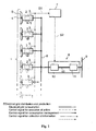
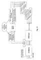
- FIG. 1 illustrates schematically the basic components comprised in a wind farm according to the invention.
- a number of wind turbine plants 1, each having a wind turbine generator 2 (WTG), controlling equipment 3 and a rotor 4 with blades 5, are producing electric power to a local AC grid 6.
- a Supervisory Control Module, in the following called Control Device 7 (CD) is arranged to collect data, through a signal connection S1, from at least one WTG 2 and to control each WTG 2 and an HVDC system 8.
- the WTGs 2 are in this case of an asynchronous fixed speed type and connected, to the AC grid 6, by the principle of an electrical torsion shaft, i.e. direct coupled to the the HVDC system 8.
- the frequency of the local grid 6 is controlled by the HVDC system 8 which is electrically connected to the grid 6.
- the HVDC system 8 is also, on its onshore side, connected to a transmission or distribution network, i.e. a public grid 9.
- the offshore and onshore parts, 10 resp 11, are typically electrically connected to each other by DC-cables 12 which reduce the transmission losses over long transmission distances.
- the figure also describes the line definitions in this and following figures. Each line may also indicate direction of action by an arrow.
- the CD according to the invention is arranged to send control signals to the HVDC system as well as to the WTG's.
- the invention uses the direct relationship between the WTG 2 speed and the wind farm AC grid 6 frequency and uses the control device to generate a signal as an order to perform frequency change, continuously or in different an interval as needed, which is sent to the offshore HVDC system 8 that, by a data signal connection S2, controls the wind farm AC grid 6 frequency.
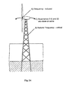
- Figure 2 illustrates a typical offshore wind turbine structure based on the sea bottom, below the sea surface.
- the tower is normally designed of a framework of metal and the whole structure is exposed to resonance due to the fact that the rotating parts, like turbine, blades and generator, induces vibrations to the structure.
- the critical structure frequency is normally within the working range of the turbine and it is important that this frequency can be avoided or passed within as short time as possible.
- FIG. 3 illustrates a block diagram of a CD.
- the CD described in this invention comprises the following features used alone or in combination to execute defined function.
- the features of the CDs function and control can be described as;
- the CD is connected to a grid controller device, project sensors and at least one WTG controller, according to the present invention.
- the WTGs and the grid controller device are both connected electrically to the controllable frequency AC grid.
- the CD comprises a central processor unit, data storage memories and input and output ports. Data from at least one WTG, like capacity (kW), turbine or generator rpm, structure vibration, electrical power output, WTG site data etc are intermittent or continuously fed to the CD.
- the WTG comprises as well of a processor that controls the WTGs functions like start/stop, pitch angle, max power output, ability to receive set points for power regulation and etc.
- the processor transmits WTG computed data to the CD and receives control signals from the CD.
- the CD collecting other data from the wind farm.
- Other data collected are e.g. actual wind speed from individual wind turbine located anemometers, wind direction from wind vanes in the project, individual wind turbine production, collective actual wind turbine production, rpm of the rotors, ambient temperature in the wind farm, air density and on-line/off-line signals from each turbine, grid frequency and torque of drive shafts. Data collected may be used individually or in combinations to establish the current settings of the wind farm.
- the CD is pre-programmed with look-up tables, which defines the performance of a rotor at each wind speed increment and at different rotor rpm's (grid frequencies).
- the collective actual production is then compared to the sum of each wind turbines calculated performance, using the measured actual wind speed at different rpm's all together summed up in total production for each rpm increment.
- the rpm group category that results in the highest total wind farm production then represents the new optimal setting value.
- the rpm value can also be adjusted for air temperature and air density (indicating energy content in wind), which may result in a slight modification to achieve highest performance (higher energy content than average - reduction in rpm and lower energy content that average - increase of rpm).
- An electrical or optical signal is then sent from the CD to the offshore HVDC station, which responds with normal frequency adjustment on the wind farm grid resulting in the new optimal rpm of the wind turbines determining the difference between the performance status and the optimal measure to take in order to calculate the necessary adjustments to achieve optimal aero dynamical performance.
- the principal of these rpm changes are done in partial load operation (below rated power) to reach wind farm optimum rpm and optimal power performance.
- the wind turbines will slow down and stop. Turbines may idle without connection to grid or be in a stand still status.
- the procedure for enabling wind turbines to start up again in as low wind speed as possible, and get them online and in operation the CD must send a signal to the offshore HVDC station to reduce its frequency to lowest level accepted within its range of operation.
- the wind turbine will hereby reach cut-in wind speed earlier in the wind speed spectrum. This increases the operative control spectrum for collective wind farm control and decreases free idling time of rotors, which is known to have negative impact on certain bearings in gearboxes.
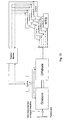
- Figure 4 illustrates a system and the main hardware and the signals used for collective control of the rotor speed (rpm) by interactive use of grid system converter technology to optimize power production and guide rotors rpm through the critical structure frequency resonance range.
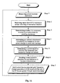
- FIG. 5 illustrates a flow chart of the general principle of the invention.
- the CD is collecting grid data, describing the grid frequency under which the individual WTGs are in operation in a group. Depending upon the gearbox ratio of the wind turbines and the number of poles in the generator, the relationship between grid frequency and rotor rpm are established and used as a direct translation of grid frequency into rotor rpm for each WTG in the group.
- the CD is also collecting performance data from each of the WTGs in the group by compiling each individual WTGs power production, blade angle setting in measurements sets in pre-defined time increments (continuous loop).
- the collection of grid data and WTG data are done in parallel, describing each value at the same point in time.
- the time increments are determined by the project operator and are defined by the necessity to make continuous changes to the rotor rpm to enhance and optimize the power production of the WTGs in a group.
- Each WTG is exposed to different wind energy content depending on its location, wind speed variations, different air temperatures, atmospheric humidity etc.
- the power production collected from each WTG defines the wind energy content at each WTG.
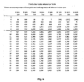
- Figure 6 illustrates a simplified Production data reference table that is used by the CD for establishing of an optimal collective rotor rpm or grid frequency.
- the Production data reference table comprises power production values representing the power production capacity for a specific type of WTG at different generator rpm's and wind speeds. This table is established by compiling fixed rpm power curves in columns, describing the relationship between wind speed and power production at a specific rotor rpm for each wind power generator in the group.
- a power curve exists for each rotor rpm increment, which for example can be with a lot higher resolution with a value for each 1/10 of an rpm, resulting in a total of 70 curves for an operational rotor rpm range of 6 -12 rpm.
- each column comprises power production capacity values for different wind speeds or wind energy contents and for one specific WTG rpm.
- the Production data reference table is pre-produced e.g. by calculations or by empirical studies of what the WTG-type in question may produce with a specific rotor and the data in the Production data reference table is based on that the WTG blade angel control is working optimally. It is also possible to include individual rpm due to generator slip, pitch angle, air density, air temperature etc and adjust the production values in the table.
- the reference values in the table may be updated when relevant new data is collected/available and the table could thereby be improved over time.
- the columns and lines in the table could be more detailed.
- the table may have a much higher resolution, i.e. more columns and lines with values, then illustrated, which would make it possible to very exactly define the production level and its related wind speed or wind energy content.
- the WTG's production status value is identified in the table, according to figure 6 , it is also possible to determine how much the WTG could produce at a change in the collective rpm, i.e. if the rpm will be higher or lower. This is principally done by identifying the production values for the same wind speed but for another rpm, a higher or lower rpm. The values, as an example on the indicated line in figure 6 , to the right and/or to the left of the present rpm column is evaluated.
- the power production values in the table at the same line (i.e. for the same wind speed).but in another rpm-column are summarized in a similar manner as described above giving possible total production values for other rpm-settings for the WTG's.
- the CD compiles each individual WTGs performance data collected and performs the same procedure for all units. By compiling the performance data and establishing the production efficiency for each WTG for each rpm increment, each collective total production for each rpm increment can be established. When this has been done for a predetermined number of rpm-columns the totals are compared to each other and the highest power production total is determined.
- the column producing the highest total power production value indicates and determines the optimal rpm-setting for the group of WTGs. Subsequently, the optimal collective rpm setting for the WTGs in a group can be established, resulting in the highest total power production of the group.
- the established new rpm setting hereby represents the new rpm or Grid frequency setting.
- This rpm value is converted/translated to a grid frequency value by the CD and sent to the GCD which in turn, directly or indirectly, controls/adjusts the WTG grid frequency and thereby the collective rpm of the WTG's and hereby effects each individual wind turbine rotor rpm collectively and subsequently each WTGs performance, resulting in the collectively highest performance of the group or the wind farm.
- Figures 7a illustrates each of five WTG's power production under a column "Meas.1". The total is determined by adding up the column, in this case resulting in a total of 1750 kW. The same numbers now represents the column 7 rpm in Figure 7b , where also the production numbers are displayed for each unit should the rpm been higher or lower.
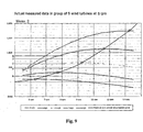
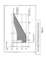
- Figures 8 and 9 illustrate diagrams that on the horizontal lines indicate the production levels at a given wind speed depending on different rpm settings (see horizontal data in Figure 6 ). Here is also marked on each curve the highest performance point on each curve with a cross in a circle, defining the optimized curve between wind speed and rpm on a WTG individual level.
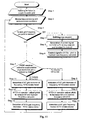
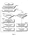
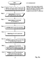
- Figure 10 shows, in a flow chart, a method for power optimization through collective variable speed of active stall regulated WTG from start and in partial load operation according to the invention.
- Optimizing of the power curve of a stall, active stall or variable pitch regulated WTG can be achieved by means of rpm adjustments by the CD (via HVDC).
- the basic principle of a stall regulated machine is based on a fixed rpm and a stall effect, which is designed to occur in such a way that overproduction, is prevented though a relationship between rotor rpm, and wind speed (wind energy content).
- the control element rests with the rotor rpm and if active stall or variable blade pitch also with adjustment of the blade pitch angle to adjust the stall effect.
- the function of the CD is to enhance and optimize the aerodynamic efficiency of the project through collective variable rotor speed and hereby improve performance from the project e.g. compared to normally fixed rotor speed operation, by collecting and compiling grid and WTG performance values, based on such values determining the measure(s) of adjusting rpm to reach improved performance, and sending signal of such measure to the offshore HVDC station for adjustment of the grid frequency and hereby controlting the rpm of the wind turbines.
- the CD collects a minimum of at least two types of information.
- the first type is individual WTG performance value such as power production, rpm, and certain meteorological data such as wind speed, wind direction, temperature, humidity etc.
- the second type is grid data such as frequency, voltage and collective power production.
- this system functions as a collective variable speed system optimizing the speed (rpm) range and aero dynamical efficiency for the wind turbines, achieving a project wide optimal power production, both with and without pitch regulation system of the blades.
- the starting frequency could be 20 Hz and maximum normal speed (rpm) for operation at rated power could be 50 Hz, the system provides for a variable speed range of 60%.
- the power optimization is achieved according to the invention by the following method steps described in a flow chart, starting with the assumption that all WTGs are in no-operation mode due to low wind speed. (WTGs are standing still or are idling at a very low speed):
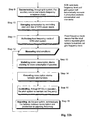
- Figure 11 shows, in a flow chart, a method for power regulation through collective variable speed with active stall and/or variable pitch regulation through common set-point for adjustment.
- This principle is possible through the use of CD, sending control signals to both HVDC grid and to WTGs in combined strategy.
- the basic control principle is to resolve a situation on a HVDC grid system where power export is limited or closed.
- the HVDC grid will in such situation be either pre-programmed or receive signal from CD to administrate any surplus inflow of power to the HVDC grid by increasing frequency and hereby store the power in form of kinetic energy in the WTG rotors.
- the base frequency is increased as a result of the power situation but is still the main frequency level, which the grid will return to as the "base frequency" after restoration of any surplus.
- the grid receives its frequency set point, so do also the WTGs by CD, here sending control set-point of the same frequency or equal rotor rpm in parallel to the WTGs.
- the WTGs will adjust pitch setting and control power production inflow to the HVDC grid system.
- the WTGs reduces production below acceptable HVDC grid export level, which results in that frequency equivalently is reduced until restored.
- close interaction can be achieved between WTGs and the HVDC grid system and power production level can be achieved through the interaction.
- Grid reflecting inflow through frequency adjustment and the WTGs regulating the inflow based on a common set-point through pitch. This process is set forth in the following example through described steps:
- Figure 9 illustrates a WTG located offshore with the components impacting resonance problem.
- Figure 14 illustrates a wind turbine and its structure resonance problems induced by the rotor and turbine.
- the resonance frequency is effected by the natural frequency of the structure.
- the critical resonance frequency is similar for each WTG throughout the wind farm as they are built in the same way and comprise the same parts.
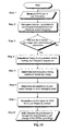
- Figure 15 shows in a flow chart, a method for avoiding resonance between rotor induced frequency and the natural design frequency of the WTG structure through collective variable speed of fixed speed induction generator connected to a WTG AC grid though the principle of an electrical torsion shaft, but where rpm is collectively regulated through grid frequency control according to the invention.
- the control and generation of signal is achieved by the CD.
- the basic principle of the invention is to achieve a collective rpm control, which indirectly also result in control of the rotor induced frequency. As all structures in a project are designed with the same range of natural design frequency, this gives the CD the ability to avoid the critical resonance range of all WTGs by the collective rpm control.
- the principle allows for two optional methods;
- This principle allows the CD to be programmed with a pre-defined range of frequency, the "red zone", which will be avoided by the CD in its control of the rpm.
- the CD will always compare a determined new frequency setting against the red zone values. When a conflict occurs, the CD will with or without delay initiate the pre-programmed ramp-up or ramp-down of frequency, giving the WTG rpm a controlled rpm change through the red zone.
- the rpm change also considers rotor acceleration and avoidance of excess loading on the WTG. This process is described in flow chart below in the following method steps:
- Figure 16 describes a control by use of resonance sensors located in the WTGs, defining activation of cross through sequence.
- This principle allows the CD to be programmed with a pre-defined range of frequency, the "red zone", which will be avoided by the CD in its control of the rpm.
- the CD will always compare a determined new frequency setting against the red zone values.
- the CD will with or without delay initiate the pre-programmed ramp-up or ramp-down of frequency, giving the WTG rpm a controlled rpm change through the red zone.
- the rpm change also considers rotor acceleration and avoidance of excess loading on the WTG.
- This method includes the following method steps:
- Figure 17 illustrates components included in a wind farm for collective frequency control for avoiding resonance, based on measured value
- Figure 18 shows a system, the hardware and signals used for achieving grid code function.
- Figure 19 shows a diagram of the voltage as a function of time at LVRT. This shows voltage dropping from 100% to 15 percent instantaneously, ramping back to 90% within 3 seconds. The requirement is for a project not to drop out of production during such an event.
- Figure 20 shows, in a flow chart, a method for achieving LVRT (grid code), by combined control by CD of both grid and WTGs, using elements of collective pitch strategy, selected shut down strategy and frequency control for ramping back frequency to normal. This is done in the following steps:
- Figure 21 shows a system, the hardware, necessary for achieving auxiliary power by operating WTG or WTGs within the project.
- Figure 22a and 22b shows, in a flow chart, the method for achieving auxiliary power by production by WTG or WTGs in the project.
- the invention is to avoid the operation and installation of expensive diesel generator stations to provide for power.
- the internal production shall provide for enough power to run necessary control and safety functions in stopped WTGs. This is done by the following steps:
- a static electric system there is a fixed relation between frequency and voltage.
- all electrical components are tuned according to these values.
- the composition of components may vary and not necessarily be tuned according to the fixed values on which a static electric power supply system is based.
- the value of having an active voltage control in parallel with an active frequency control is increasing. Consequently different degrees of optimization could be necessary for different components in order to achieve optimal energy output.
- a cable system and equipment for fixed capacitor batteries (fixed phase compensation) has an opposite reaction to voltage control compared to a transformer or a generator. Consequently optimization can be done by controlling the voltage in a system perspective where a multiple of generators, motors, cable systems, transformers, phase compensations etc are considered.
- a change of the frequency influences the magnetic flow in the iron core in a specific asynchronous type of a generator that thereby influences the losses and the heating. This characteristic differs from generator to generator. If only the frequency is changed, the losses in the unit will increase. This means that by also adjusting the voltage the efficiency of the component may be influenced and thereby improve the efficiency of the unit in the system. As an example, by reduction of the grid frequency it is also possible in parallel to decrease the voltage in such a way that the current flow decreases at low frequencies, and hereby the losses in a generator are reduced.
- the iron cores of transformers are affected in the same manner.
- a HVDC-Light system has lower losses if transferring lower power capacity levels at lower DC voltage.
- the total losses will be lower when transferring lower power levels if lower AC voltage is used in combination with lower DC voltage, i.e. when the frequency is low.
Landscapes
- Engineering & Computer Science (AREA)
- Power Engineering (AREA)
- Life Sciences & Earth Sciences (AREA)
- Sustainable Development (AREA)
- Sustainable Energy (AREA)
- Chemical & Material Sciences (AREA)
- Combustion & Propulsion (AREA)
- Mechanical Engineering (AREA)
- General Engineering & Computer Science (AREA)
- Wind Motors (AREA)
- Control Of Eletrric Generators (AREA)
Claims (6)
- Verfahren zum Steuern des Betriebs eines Windparks (1), um eine optimale Leistungserzeugung zu erzielen, umfassend wenigstens zwei Generatoren von Windturbinen (3) des asynchronen Generatortyps (6) mit unveränderlicher Drehzahl, die in Verwendung jeweils mit einem frequenzgesteuerten Wechselstromnetz durch das Prinzip einer elektrischen Torsionswelle verbunden sind, direkt gekoppelt mit einem HVDC-System (10),
gekennzeichnet durch folgende Schritte:- Erfassen wenigstens eines aktuellen Parameters, der die lokale Netzfrequenz repräsentiert,- Erfassen wenigstens eines momentanen Wertes, der sich auf das Leistungsverhalten eines individuellen Generators der Windturbine (3) bezieht, wie etwa Umdrehungen pro Minute, und/oder eines Wertes, der die Windturbinengenerator-Stromerzeugung wenigstens zweier Windturbinengeneratoren (6) in dem Windpark (1) repräsentiert,- Verwenden von Bezugsdaten, die Werte eines individuellen Windturbinengenerators (6) enthalten, die die Stromerzeugungskapazität bei unterschiedlichen Umdrehungen pro Minute der Turbine und für unterschiedlichen Windeenergiegehalt oder Windgeschwindigkeiten repräsentieren,- Bestimmen auf der Basis der erfassten Werte und Bezugsdaten für den individuellen Windturbinengenerator (6), durch Vergleichen und Abstimmen der momentanen Leistungsdaten mit den Bezugsdaten, der Stromerzeugungsänderung der einzelnen Windturbinen (3) infolge der Änderungen der Umdrehung pro Minute,- Bestimmen auf der Basis individueller momentaner Leistungsdaten für wenigstens zwei Windturbinengeneratoren (6) der gesamten Stromerzeugungsdifferenz infolge der Änderung der gesamten Umdrehungen pro Minute oder der Netzfrequenz,- Bestimmen auf der Basis der gesamten Stromerzeugung der Windturbinen (3) bei unterschiedlichen Umdrehung pro Minute der optimalen Umdrehungen pro Minute und der entsprechenden Netzfrequenz, um die höchste gesamte Stromerzeugung zu erzielen, und- Ändern der Netzfrequenz durch die Netzsteuervorrichtung auf die bestimmte optimale Netzfrequenzeinstellung. - Verfahren nach Anspruch 1, gekennzeichnet durch den weiteren Schritt- des Zusammenstellens der Bezugsdaten, die Stromerzeugungswerte beinhalten, in einer Produktionsdatenbezugstabelle.
- Verfahren nach einem der vorhergehenden Ansprüche, gekennzeichnet durch- Erfassen meteorologischer Daten zum Bestimmen des Energiegehaltes in dem Wind.
- Verfahren nach einem der vorhergehenden Ansprüche, gekennzeichnet durch den weiteren Schritt- des Verwendens der Windrichtung, der Lufttemperatur und/oder der Luftfeuchtigkeit als meteorologische Daten.
- System zum Steuern des Betriebs eines Windparks (1), um eine optimale Leistungserzeugung zu erzielen, umfassend wenigstens zwei Generatoren von Windturbinen (3) des asynchronen Generatortyps (6) mit unveränderlicher Drehzahl, die in Verwendung jeweils mit einer Wechselstromseite eines frequenzgesteuerten Netzes durch das Prinzip einer elektrischen Torsionswelle verbunden sind, direkt gekoppelt mit einem HVDC-System (10),
gekennzeichnet dadurch, dass:- ein Speicher dazu eingerichtet ist, Bezugsdaten zu speichern, die die Stromerzeugung eines individuellen Windturbinengenerators (6) bei unterschiedlichen Windgeschwindigkeiten und unterschiedlichen Umdrehungen pro Minute der Turbine repräsentieren,- Einrichtungen dazu eingerichtet sind, wenigstens einen aktuellen Parameter zu erfassen, der die Netzfrequenz repräsentiert,- Einrichtungen dazu eingerichtet sind, wenigstens einen momentanen Wert, der sich auf das Leistungsverhalten eines individuellen Generators der Windturbine (3) bezieht, wie etwa Umdrehungen pro Minute, und/oder einen Wert, der die Windturbinengenerator-Stromerzeugung wenigstens zweier Windturbinengeneratoren (6) in dem Windpark (1) repräsentiert, zu erfassen- Einrichtungen dazu eingerichtet sind, Bezugsdaten zu verwenden, die Werte eines individuellen Windturbinengenerators (6) enthalten, die die Stromerzeugungskapazität bei unterschiedlichen Umdrehungen pro Minute der Turbine und für unterschiedlichen Windeenergiegehalt oder Windgeschwindigkeiten repräsentieren,- Einrichtungen dazu eingerichtet sind, auf der Basis der erfassten Werte und Bezugsdaten für den individuellen Windturbinengenerator (6), durch Vergleichen und Abstimmen der momentanen Leistungsdaten mit den Bezugsdaten, die Stromerzeugungsänderung der einzelnen Windturbinen (3) infolge der Änderungen der Umdrehung pro Minute zu bestimmen,- Einrichtungen dazu eingerichtet sind, auf der Basis individueller momentaner Leistungsdaten für wenigstens zwei Windturbinengeneratoren (6) die gesamte Stromerzeugungsdifferenz infolge der Änderung der gesamten Umdrehungen pro Minute oder der Netzfrequenz zu bestimmen,- Einrichtungen dazu eingerichtet sind, auf der Basis der gesamten Stromerzeugung der Windturbinen (3) bei unterschiedlichen Umdrehungen pro Minute die optimalen Umdrehungen pro Minute und die entsprechenden Netzfrequenz zu bestimmen, um die höchste gesamte Stromerzeugung zu erzielen, und- Einrichtungen dazu eingerichtet sind, die Netzfrequenz durch die Netzsteuervorrichtung auf die bestimmte optimale Netzfrequenzeinstellung zu ändern. - Computerprogrammerzeugnis zum Steuern des Betriebs eines Windparks (1), der eine Gruppe von wenigstens zwei Generatoren von Windturbinen (3) (WTGs) des asynchronen Generatortyps mit unveränderlicher Drehzahl hat, die in Verwendung jeweils mit einem WTG-Netz durch das Prinzip einer elektrischen Torsionswelle verbunden sind, wobei, wenn das Computerprogrammerzeugnis auf einen Computer geladen ist und auf einem Computer läuft, den Computer zu folgenden Tätigkeiten veranlasst:- Erfassen wenigstens eines aktuellen Parameters, der die Netzfrequenz repräsentiert,- Erfassen wenigstens eines momentanen Wertes, der sich auf das Leistungsverhalten eines individuellen Generators der Windturbine (3) bezieht, wie etwa Umdrehungen pro Minute, und/oder eines Wertes, der die Windturbinengenerator-Stromerzeugung wenigstens zweier Windturbinengeneratoren in dem Windpark (1) repräsentiert,- Verwenden von Bezugsdaten, die Werte eines individuellen Windturbinengenerators (6) enthalten, die die Stromerzeugungskapazität bei unterschiedlichen Umdrehungen pro Minute der Turbine und für unterschiedlichen Windeenergiegehalt oder Windgeschwindigkeiten repräsentieren,- Bestimmen auf der Basis der erfassten Werte und Bezugsdaten für den individuellen Windturbinengenerator, durch Vergleichen und Abstimmen der momentanen Leistungsdaten mit den Bezugsdaten, der Stromerzeugungsänderung der einzelnen Windturbinen infolge der Änderungen der Umdrehung pro Minute,- Bestimmen auf der Basis individueller momentaner Leistungsdaten für wenigstens zwei Windturbinengeneratoren der gesamten Stromerzeugungsdifferenz infolge der Änderung der gesamten Umdrehungen pro Minute oder der Netzfrequenz,- Bestimmen auf der Basis der gesamten Stromerzeugung der Windturbinen bei unterschiedlichen Umdrehung pro Minute der optimalen Umdrehungen pro Minute und der entsprechenden Netzfrequenz, um die höchste gesamte Stromerzeugung zu erzielen, und- Ändern der Netzfrequenz durch die Netzsteuervorrichtung auf die bestimmte optimale Netzfrequenzeinstellung.
Applications Claiming Priority (3)
| Application Number | Priority Date | Filing Date | Title |
|---|---|---|---|
| SE0702878 | 2007-12-21 | ||
| SE0800291 | 2008-02-08 | ||
| PCT/SE2008/000741 WO2009082326A1 (en) | 2007-12-21 | 2008-12-22 | Method, system and device for controlling wind power plants |
Publications (3)
| Publication Number | Publication Date |
|---|---|
| EP2232667A1 EP2232667A1 (de) | 2010-09-29 |
| EP2232667A4 EP2232667A4 (de) | 2011-06-15 |
| EP2232667B1 true EP2232667B1 (de) | 2013-01-23 |
Family
ID=40352143
Family Applications (2)
| Application Number | Title | Priority Date | Filing Date |
|---|---|---|---|
| EP08753768.4A Not-in-force EP2235367B1 (de) | 2007-12-21 | 2008-05-14 | Windpark |
| EP08864798A Not-in-force EP2232667B1 (de) | 2007-12-21 | 2008-12-22 | Verfahren und system zur steuerung von windenergieanlagen |
Family Applications Before (1)
| Application Number | Title | Priority Date | Filing Date |
|---|---|---|---|
| EP08753768.4A Not-in-force EP2235367B1 (de) | 2007-12-21 | 2008-05-14 | Windpark |
Country Status (3)
| Country | Link |
|---|---|
| EP (2) | EP2235367B1 (de) |
| DK (1) | DK2235367T3 (de) |
| WO (2) | WO2009082204A1 (de) |
Cited By (3)
| Publication number | Priority date | Publication date | Assignee | Title |
|---|---|---|---|---|
| US9690884B2 (en) | 2013-06-05 | 2017-06-27 | WindLogics Inc. | Wind farm prediction of potential and actual power generation |
| US10724501B2 (en) | 2014-02-06 | 2020-07-28 | Ge Renewable Technologies Wind B.V. | Methods and systems of operating a set of wind turbines |
| US12413073B2 (en) | 2020-06-28 | 2025-09-09 | Xinjiang Goldwind Science & Technology Co., Ltd. | Method and apparatus for controlling power of wind farm |
Families Citing this family (32)
| Publication number | Priority date | Publication date | Assignee | Title |
|---|---|---|---|---|
| DE202009018444U1 (de) * | 2009-12-22 | 2011-09-29 | 2-B Energy B.V. | Windkraftanlage |
| CN102121966B (zh) * | 2010-01-07 | 2013-04-10 | 华北电力科学研究院有限责任公司 | 风力发电机低电压穿越能力的测量方法和分析系统 |
| DE102010000838A1 (de) * | 2010-01-12 | 2011-07-14 | SkyWind GmbH, 24782 | Verfahren und Vorrichtung zum Aufsynchronisieren eines Generators in einem Netz |
| DE102010000837A1 (de) * | 2010-01-12 | 2011-07-14 | SkyWind GmbH, 24782 | Verfahren zur Verminderung der Komplexität von Windenergieanlagen im Windparkverbund und Anordnung eines Windparks |
| CN102142688B (zh) * | 2010-01-29 | 2015-07-08 | 西门子公司 | 电能并网系统以及电能传输系统和方法 |
| US9178456B2 (en) | 2010-04-06 | 2015-11-03 | Ge Energy Power Conversion Technology, Ltd. | Power transmission systems |
| EP2375529B1 (de) * | 2010-04-06 | 2013-08-14 | Converteam Technology Ltd | Stromübertragungssystem umfassend eine mehrheit von turbinen erneuerbarer energie |
| US8463451B2 (en) * | 2010-04-19 | 2013-06-11 | General Electric Company | Automatic primary frequency response contribution monitoring system and method |
| US7939970B1 (en) * | 2010-07-26 | 2011-05-10 | General Electric Company | Variable frequency wind plant |
| EP2458205B1 (de) | 2010-11-26 | 2016-10-19 | Siemens Aktiengesellschaft | Verfahren und System zur Steuerung einer elektrischen Vorrichtung einer Windturbine |
| CN102024079B (zh) * | 2010-12-01 | 2013-06-12 | 中国电力科学研究院 | 一种大型风电场电磁暂态仿真的等效聚合模拟方法 |
| KR101093003B1 (ko) | 2011-02-09 | 2011-12-12 | 전북대학교산학협력단 | 급격한 풍속 변화시 풍력발전단지 제어 방법 및 시스템 |
| EP2495839A1 (de) * | 2011-03-02 | 2012-09-05 | ABB Technology AG | Energiesystem |
| CN102290855B (zh) * | 2011-07-08 | 2014-01-15 | 三一电气有限责任公司 | 一种风电场联合保护装置及方法、风力发电系统 |
| CN104145390B (zh) * | 2012-03-09 | 2018-04-10 | Abb 技术有限公司 | 用于使用电单元的方法 |
| EP2908004B1 (de) * | 2013-01-15 | 2016-10-12 | Mitsubishi Heavy Industries, Ltd. | Windenergieerzeugungsanlage, verfahren zum betrieb davon und windparksteuerungsvorrichtung |
| RU2595643C2 (ru) * | 2014-09-04 | 2016-08-27 | федеральное государственное бюджетное образовательное учреждение высшего образования "Нижегородский государственный технический университет им. Р.Е. Алексеева" (НГТУ) | Ветроэнергетическая установка с системой автоматического регулирования |
| EP3001553A1 (de) * | 2014-09-25 | 2016-03-30 | ABB Oy | Elektrische Anordnung |
| WO2016066188A1 (de) * | 2014-10-28 | 2016-05-06 | Siemens Aktiengesellschaft | Umrichteranordnung mit einer mehrzahl von umrichtern für einen windpark |
| DE102015201431A1 (de) | 2015-01-28 | 2016-07-28 | Wobben Properties Gmbh | Verfahren zum Betreiben eines Windparks |
| ES2900760T3 (es) * | 2015-12-17 | 2022-03-18 | Vestas Wind Sys As | Modulación de salida de planta de energía eólica usando diferentes componentes de modulación de frecuencia para amortiguar oscilaciones de red |
| US10240581B2 (en) | 2017-02-08 | 2019-03-26 | General Electric Company | System and method for controlling pitch angle of a wind turbine rotor blade |
| US10615608B2 (en) | 2017-04-07 | 2020-04-07 | General Electric Company | Low-wind operation of clustered doubly fed induction generator wind turbines |
| DE102017122695A1 (de) | 2017-09-29 | 2019-04-04 | Wobben Properties Gmbh | Verfahren zum Versorgen von Windenergieanlagenkomponenten mit Energie sowie Energieversorgungseinrichtung und Windenergieanlage damit |
| CN110854901B (zh) * | 2019-10-21 | 2021-09-28 | 明阳智慧能源集团股份公司 | 一种风力发电机组黑启动方法 |
| ES2940097T3 (es) * | 2019-12-20 | 2023-05-03 | Schneider Toshiba Inverter Europe Sas | Procedimientos y dispositivos para determinar una frecuencia de resonancia de un sistema mecánico |
| CN113765135A (zh) * | 2020-06-02 | 2021-12-07 | 中国石油化工股份有限公司 | 一种直驱异步风力发电机系统 |
| CN111884229B (zh) * | 2020-08-19 | 2022-03-08 | 南方电网科学研究院有限责任公司 | 背靠背柔性直流输电系统的异同步控制方法及系统 |
| EP4074960A1 (de) * | 2021-04-13 | 2022-10-19 | Wobben Properties GmbH | Verfahren zum betreiben eines windparks und windpark |
| CN114094577B (zh) * | 2021-11-25 | 2023-11-17 | 中国三峡建工(集团)有限公司 | 一种海上风电送出系统稳控与耗能装置协调配合方法 |
| CN117145709A (zh) * | 2023-09-04 | 2023-12-01 | 华能阿荣旗安泰风力发电有限公司 | 风电机组控制方法、装置、设备及计算机可读存储介质 |
| CN121036223A (zh) * | 2025-09-05 | 2025-11-28 | 中国电力工程顾问集团有限公司 | 适用于高空风力发电的多伞梯机组协同控制方法及装置 |
Family Cites Families (14)
| Publication number | Priority date | Publication date | Assignee | Title |
|---|---|---|---|---|
| DE2922972C2 (de) * | 1978-06-15 | 1986-11-13 | United Technologies Corp., Hartford, Conn. | Windturbinenregelsystem |
| SE514934C2 (sv) * | 1999-09-06 | 2001-05-21 | Abb Ab | Anläggning för generering av elektrisk effekt med hjälp av vindkraftspark samt förfarande för drift av en sådan anlägning. |
| SE9904753L (sv) * | 1999-12-23 | 2001-06-24 | Abb Ab | Användning av HVDC-isolerad ledare i magnetiska flödesbärare |
| DE20001864U1 (de) | 2000-02-03 | 2000-04-20 | Siemens AG, 80333 München | Windradgruppe mit zumindest zwei Windrädern |
| DE10016912C1 (de) | 2000-04-05 | 2001-12-13 | Aerodyn Eng Gmbh | Turmeigenfrequenzabhängige Betriebsführung von Offshore-Windenergieanlagen |
| US20020029097A1 (en) | 2000-04-07 | 2002-03-07 | Pionzio Dino J. | Wind farm control system |
| WO2002054561A2 (en) * | 2000-12-29 | 2002-07-11 | Abb Ab | System, method and computer program product for enhancing commercial value of electrical power produced from a renewable energy power production facility |
| US20020084655A1 (en) * | 2000-12-29 | 2002-07-04 | Abb Research Ltd. | System, method and computer program product for enhancing commercial value of electrical power produced from a renewable energy power production facility |
| AU2002340927B2 (en) | 2001-09-28 | 2006-09-14 | Aloys Wobben | Method for operating a wind park |
| DE10320087B4 (de) | 2003-05-05 | 2005-04-28 | Aloys Wobben | Verfahren zum Betreiben eines Windparks |
| GB2410386A (en) * | 2004-01-22 | 2005-07-27 | Areva T & D Uk Ltd | Controlling reactive power output |
| ES2694977T3 (es) * | 2004-03-05 | 2018-12-28 | Gamesa Innovation & Technology, S.L. | Sistema de regulación de potencia activa de un parque eólico |
| DE102005043422B4 (de) | 2005-09-07 | 2016-11-10 | Joachim Falkenhagen | Betrieb eines lokalen Netzes mit reduzierter Frequenz bei geringer Energieübertragung |
| DE102006008014A1 (de) * | 2006-02-21 | 2007-08-30 | Repower Systems Ag | Windenergieanlage mit Zusatzschaltung für Schwachwindbetrieb. |
-
2008
- 2008-05-14 WO PCT/NL2008/050285 patent/WO2009082204A1/en not_active Ceased
- 2008-05-14 EP EP08753768.4A patent/EP2235367B1/de not_active Not-in-force
- 2008-05-14 DK DK08753768.4T patent/DK2235367T3/en active
- 2008-12-22 WO PCT/SE2008/000741 patent/WO2009082326A1/en not_active Ceased
- 2008-12-22 EP EP08864798A patent/EP2232667B1/de not_active Not-in-force
Cited By (3)
| Publication number | Priority date | Publication date | Assignee | Title |
|---|---|---|---|---|
| US9690884B2 (en) | 2013-06-05 | 2017-06-27 | WindLogics Inc. | Wind farm prediction of potential and actual power generation |
| US10724501B2 (en) | 2014-02-06 | 2020-07-28 | Ge Renewable Technologies Wind B.V. | Methods and systems of operating a set of wind turbines |
| US12413073B2 (en) | 2020-06-28 | 2025-09-09 | Xinjiang Goldwind Science & Technology Co., Ltd. | Method and apparatus for controlling power of wind farm |
Also Published As
| Publication number | Publication date |
|---|---|
| EP2232667A1 (de) | 2010-09-29 |
| EP2235367B1 (de) | 2016-03-16 |
| EP2235367A1 (de) | 2010-10-06 |
| WO2009082326A1 (en) | 2009-07-02 |
| EP2232667A4 (de) | 2011-06-15 |
| WO2009082204A1 (en) | 2009-07-02 |
| DK2235367T3 (en) | 2016-06-27 |
Similar Documents
| Publication | Publication Date | Title |
|---|---|---|
| EP2232667B1 (de) | Verfahren und system zur steuerung von windenergieanlagen | |
| US10731629B2 (en) | Wind power plant controller | |
| US8994200B2 (en) | Power system frequency inertia for power generation system | |
| EP2847457B1 (de) | Stromsystem und verfahren zum betreiben einer windenergieanlage mit einem verteilungsalgorithmus | |
| US7002259B2 (en) | Method of controlling electrical rotating machines connected to a common shaft | |
| EP3149325B1 (de) | Windkraftanlage mit verringerten verlusten | |
| EP2688172B1 (de) | Verfahren und Vorrichtung zur adaptiven Steuerung von Windparkturbinen | |
| US20110285130A1 (en) | Power System Frequency Inertia for Wind Turbines | |
| EP2658112B1 (de) | Verfahren und Systeme zur Steuerung eines Stromwandlers | |
| WO2014056504A2 (en) | Line impedance compensation system | |
| EP3926781A1 (de) | Windkraftwerk mit konvertierungssystem | |
| EP2573894A2 (de) | Verfahren und Systeme für den Betrieb eines Stromerzeugungs- und -versorgungssystems | |
| CN101672254B (zh) | 风电场及其控制方法 | |
| EP3738186B1 (de) | System und verfahren zur optmierung der reaktiven energieerzeugung eines windparks | |
| EP3728839B1 (de) | Steuerung der leistungsrampengeschwindigkeit | |
| CN208209537U (zh) | 一种风电次同步振荡监测调节系统 | |
| Han et al. | Research on frequency regulation of power system containing wind farm | |
| Kalfić et al. | Example of Matlab/Simulink Tool Usage for Evaluation of Wind Turbine Operation During Voltage Regulation and Reactive Power Regulation | |
| Saleh et al. | European Journal of Electrical Engineering | |
| Mutlu | Effect of wind turbines on power system operation | |
| Iov et al. | Variable Frequency Operation of Active Stall Wind Farms using a DC Connection to Grid | |
| Abomahdi et al. | TRANSIENT ANALYSIS AND MODELING OF WIND GENERATOR DURING POWER & GRID VOLTAGE DROP |
Legal Events
| Date | Code | Title | Description |
|---|---|---|---|
| PUAI | Public reference made under article 153(3) epc to a published international application that has entered the european phase |
Free format text: ORIGINAL CODE: 0009012 |
|
| 17P | Request for examination filed |
Effective date: 20100701 |
|
| AK | Designated contracting states |
Kind code of ref document: A1 Designated state(s): AT BE BG CH CY CZ DE DK EE ES FI FR GB GR HR HU IE IS IT LI LT LU LV MC MT NL NO PL PT RO SE SI SK TR |
|
| AX | Request for extension of the european patent |
Extension state: AL BA MK RS |
|
| DAX | Request for extension of the european patent (deleted) | ||
| REG | Reference to a national code |
Ref country code: DE Ref legal event code: R079 Ref document number: 602008021946 Country of ref document: DE Free format text: PREVIOUS MAIN CLASS: H02J0003380000 Ipc: F03D0007040000 |
|
| A4 | Supplementary search report drawn up and despatched |
Effective date: 20110512 |
|
| RIC1 | Information provided on ipc code assigned before grant |
Ipc: F03D 9/00 20060101ALI20110506BHEP Ipc: F03D 7/04 20060101AFI20110506BHEP |
|
| RIC1 | Information provided on ipc code assigned before grant |
Ipc: F03D 9/00 20060101ALI20120124BHEP Ipc: F03D 7/04 20060101AFI20120124BHEP Ipc: H02J 3/38 20060101ALI20120124BHEP |
|
| RTI1 | Title (correction) |
Free format text: METHOD AND SYSTEM FOR CONTROLLING WIND POWER PLANTS |
|
| GRAP | Despatch of communication of intention to grant a patent |
Free format text: ORIGINAL CODE: EPIDOSNIGR1 |
|
| GRAS | Grant fee paid |
Free format text: ORIGINAL CODE: EPIDOSNIGR3 |
|
| GRAA | (expected) grant |
Free format text: ORIGINAL CODE: 0009210 |
|
| AK | Designated contracting states |
Kind code of ref document: B1 Designated state(s): AT BE BG CH CY CZ DE DK EE ES FI FR GB GR HR HU IE IS IT LI LT LU LV MC MT NL NO PL PT RO SE SI SK TR |
|
| REG | Reference to a national code |
Ref country code: GB Ref legal event code: FG4D |
|
| REG | Reference to a national code |
Ref country code: CH Ref legal event code: EP |
|
| REG | Reference to a national code |
Ref country code: AT Ref legal event code: REF Ref document number: 595121 Country of ref document: AT Kind code of ref document: T Effective date: 20130215 Ref country code: CH Ref legal event code: EP |
|
| REG | Reference to a national code |
Ref country code: IE Ref legal event code: FG4D |
|
| REG | Reference to a national code |
Ref country code: DE Ref legal event code: R096 Ref document number: 602008021946 Country of ref document: DE Effective date: 20130321 |
|
| REG | Reference to a national code |
Ref country code: AT Ref legal event code: MK05 Ref document number: 595121 Country of ref document: AT Kind code of ref document: T Effective date: 20130123 |
|
| REG | Reference to a national code |
Ref country code: LT Ref legal event code: MG4D |
|
| REG | Reference to a national code |
Ref country code: NL Ref legal event code: VDEP Effective date: 20130123 |
|
| PG25 | Lapsed in a contracting state [announced via postgrant information from national office to epo] |
Ref country code: ES Free format text: LAPSE BECAUSE OF FAILURE TO SUBMIT A TRANSLATION OF THE DESCRIPTION OR TO PAY THE FEE WITHIN THE PRESCRIBED TIME-LIMIT Effective date: 20130504 Ref country code: BG Free format text: LAPSE BECAUSE OF FAILURE TO SUBMIT A TRANSLATION OF THE DESCRIPTION OR TO PAY THE FEE WITHIN THE PRESCRIBED TIME-LIMIT Effective date: 20130423 Ref country code: SE Free format text: LAPSE BECAUSE OF FAILURE TO SUBMIT A TRANSLATION OF THE DESCRIPTION OR TO PAY THE FEE WITHIN THE PRESCRIBED TIME-LIMIT Effective date: 20130123 Ref country code: BE Free format text: LAPSE BECAUSE OF FAILURE TO SUBMIT A TRANSLATION OF THE DESCRIPTION OR TO PAY THE FEE WITHIN THE PRESCRIBED TIME-LIMIT Effective date: 20130123 Ref country code: NO Free format text: LAPSE BECAUSE OF FAILURE TO SUBMIT A TRANSLATION OF THE DESCRIPTION OR TO PAY THE FEE WITHIN THE PRESCRIBED TIME-LIMIT Effective date: 20130423 Ref country code: AT Free format text: LAPSE BECAUSE OF FAILURE TO SUBMIT A TRANSLATION OF THE DESCRIPTION OR TO PAY THE FEE WITHIN THE PRESCRIBED TIME-LIMIT Effective date: 20130123 Ref country code: LT Free format text: LAPSE BECAUSE OF FAILURE TO SUBMIT A TRANSLATION OF THE DESCRIPTION OR TO PAY THE FEE WITHIN THE PRESCRIBED TIME-LIMIT Effective date: 20130123 Ref country code: IS Free format text: LAPSE BECAUSE OF FAILURE TO SUBMIT A TRANSLATION OF THE DESCRIPTION OR TO PAY THE FEE WITHIN THE PRESCRIBED TIME-LIMIT Effective date: 20130523 |
|
| PG25 | Lapsed in a contracting state [announced via postgrant information from national office to epo] |
Ref country code: FI Free format text: LAPSE BECAUSE OF FAILURE TO SUBMIT A TRANSLATION OF THE DESCRIPTION OR TO PAY THE FEE WITHIN THE PRESCRIBED TIME-LIMIT Effective date: 20130123 Ref country code: LV Free format text: LAPSE BECAUSE OF FAILURE TO SUBMIT A TRANSLATION OF THE DESCRIPTION OR TO PAY THE FEE WITHIN THE PRESCRIBED TIME-LIMIT Effective date: 20130123 Ref country code: NL Free format text: LAPSE BECAUSE OF FAILURE TO SUBMIT A TRANSLATION OF THE DESCRIPTION OR TO PAY THE FEE WITHIN THE PRESCRIBED TIME-LIMIT Effective date: 20130123 Ref country code: SI Free format text: LAPSE BECAUSE OF FAILURE TO SUBMIT A TRANSLATION OF THE DESCRIPTION OR TO PAY THE FEE WITHIN THE PRESCRIBED TIME-LIMIT Effective date: 20130123 Ref country code: PL Free format text: LAPSE BECAUSE OF FAILURE TO SUBMIT A TRANSLATION OF THE DESCRIPTION OR TO PAY THE FEE WITHIN THE PRESCRIBED TIME-LIMIT Effective date: 20130123 Ref country code: PT Free format text: LAPSE BECAUSE OF FAILURE TO SUBMIT A TRANSLATION OF THE DESCRIPTION OR TO PAY THE FEE WITHIN THE PRESCRIBED TIME-LIMIT Effective date: 20130523 Ref country code: GR Free format text: LAPSE BECAUSE OF FAILURE TO SUBMIT A TRANSLATION OF THE DESCRIPTION OR TO PAY THE FEE WITHIN THE PRESCRIBED TIME-LIMIT Effective date: 20130424 |
|
| PG25 | Lapsed in a contracting state [announced via postgrant information from national office to epo] |
Ref country code: HR Free format text: LAPSE BECAUSE OF FAILURE TO SUBMIT A TRANSLATION OF THE DESCRIPTION OR TO PAY THE FEE WITHIN THE PRESCRIBED TIME-LIMIT Effective date: 20130123 |
|
| PG25 | Lapsed in a contracting state [announced via postgrant information from national office to epo] |
Ref country code: DK Free format text: LAPSE BECAUSE OF FAILURE TO SUBMIT A TRANSLATION OF THE DESCRIPTION OR TO PAY THE FEE WITHIN THE PRESCRIBED TIME-LIMIT Effective date: 20130123 Ref country code: RO Free format text: LAPSE BECAUSE OF FAILURE TO SUBMIT A TRANSLATION OF THE DESCRIPTION OR TO PAY THE FEE WITHIN THE PRESCRIBED TIME-LIMIT Effective date: 20130123 Ref country code: CZ Free format text: LAPSE BECAUSE OF FAILURE TO SUBMIT A TRANSLATION OF THE DESCRIPTION OR TO PAY THE FEE WITHIN THE PRESCRIBED TIME-LIMIT Effective date: 20130123 Ref country code: EE Free format text: LAPSE BECAUSE OF FAILURE TO SUBMIT A TRANSLATION OF THE DESCRIPTION OR TO PAY THE FEE WITHIN THE PRESCRIBED TIME-LIMIT Effective date: 20130123 Ref country code: SK Free format text: LAPSE BECAUSE OF FAILURE TO SUBMIT A TRANSLATION OF THE DESCRIPTION OR TO PAY THE FEE WITHIN THE PRESCRIBED TIME-LIMIT Effective date: 20130123 |
|
| PG25 | Lapsed in a contracting state [announced via postgrant information from national office to epo] |
Ref country code: CY Free format text: LAPSE BECAUSE OF FAILURE TO SUBMIT A TRANSLATION OF THE DESCRIPTION OR TO PAY THE FEE WITHIN THE PRESCRIBED TIME-LIMIT Effective date: 20130123 |
|
| PLBE | No opposition filed within time limit |
Free format text: ORIGINAL CODE: 0009261 |
|
| STAA | Information on the status of an ep patent application or granted ep patent |
Free format text: STATUS: NO OPPOSITION FILED WITHIN TIME LIMIT |
|
| PG25 | Lapsed in a contracting state [announced via postgrant information from national office to epo] |
Ref country code: IT Free format text: LAPSE BECAUSE OF FAILURE TO SUBMIT A TRANSLATION OF THE DESCRIPTION OR TO PAY THE FEE WITHIN THE PRESCRIBED TIME-LIMIT Effective date: 20130123 |
|
| 26N | No opposition filed |
Effective date: 20131024 |
|
| REG | Reference to a national code |
Ref country code: DE Ref legal event code: R097 Ref document number: 602008021946 Country of ref document: DE Effective date: 20131024 |
|
| PG25 | Lapsed in a contracting state [announced via postgrant information from national office to epo] |
Ref country code: MC Free format text: LAPSE BECAUSE OF FAILURE TO SUBMIT A TRANSLATION OF THE DESCRIPTION OR TO PAY THE FEE WITHIN THE PRESCRIBED TIME-LIMIT Effective date: 20130123 |
|
| REG | Reference to a national code |
Ref country code: CH Ref legal event code: PL |
|
| PG25 | Lapsed in a contracting state [announced via postgrant information from national office to epo] |
Ref country code: LU Free format text: LAPSE BECAUSE OF FAILURE TO SUBMIT A TRANSLATION OF THE DESCRIPTION OR TO PAY THE FEE WITHIN THE PRESCRIBED TIME-LIMIT Effective date: 20131222 |
|
| REG | Reference to a national code |
Ref country code: IE Ref legal event code: MM4A |
|
| REG | Reference to a national code |
Ref country code: FR Ref legal event code: ST Effective date: 20140829 |
|
| PG25 | Lapsed in a contracting state [announced via postgrant information from national office to epo] |
Ref country code: CH Free format text: LAPSE BECAUSE OF NON-PAYMENT OF DUE FEES Effective date: 20131231 Ref country code: LI Free format text: LAPSE BECAUSE OF NON-PAYMENT OF DUE FEES Effective date: 20131231 Ref country code: IE Free format text: LAPSE BECAUSE OF NON-PAYMENT OF DUE FEES Effective date: 20131222 |
|
| PG25 | Lapsed in a contracting state [announced via postgrant information from national office to epo] |
Ref country code: FR Free format text: LAPSE BECAUSE OF NON-PAYMENT OF DUE FEES Effective date: 20131231 |
|
| PG25 | Lapsed in a contracting state [announced via postgrant information from national office to epo] |
Ref country code: TR Free format text: LAPSE BECAUSE OF FAILURE TO SUBMIT A TRANSLATION OF THE DESCRIPTION OR TO PAY THE FEE WITHIN THE PRESCRIBED TIME-LIMIT Effective date: 20130123 |
|
| PG25 | Lapsed in a contracting state [announced via postgrant information from national office to epo] |
Ref country code: HU Free format text: LAPSE BECAUSE OF FAILURE TO SUBMIT A TRANSLATION OF THE DESCRIPTION OR TO PAY THE FEE WITHIN THE PRESCRIBED TIME-LIMIT; INVALID AB INITIO Effective date: 20081222 |
|
| PG25 | Lapsed in a contracting state [announced via postgrant information from national office to epo] |
Ref country code: MT Free format text: LAPSE BECAUSE OF FAILURE TO SUBMIT A TRANSLATION OF THE DESCRIPTION OR TO PAY THE FEE WITHIN THE PRESCRIBED TIME-LIMIT Effective date: 20130123 |
|
| PGFP | Annual fee paid to national office [announced via postgrant information from national office to epo] |
Ref country code: GB Payment date: 20181219 Year of fee payment: 11 |
|
| PGFP | Annual fee paid to national office [announced via postgrant information from national office to epo] |
Ref country code: DE Payment date: 20190214 Year of fee payment: 11 |
|
| REG | Reference to a national code |
Ref country code: DE Ref legal event code: R119 Ref document number: 602008021946 Country of ref document: DE |
|
| GBPC | Gb: european patent ceased through non-payment of renewal fee |
Effective date: 20191222 |
|
| PG25 | Lapsed in a contracting state [announced via postgrant information from national office to epo] |
Ref country code: GB Free format text: LAPSE BECAUSE OF NON-PAYMENT OF DUE FEES Effective date: 20191222 Ref country code: DE Free format text: LAPSE BECAUSE OF NON-PAYMENT OF DUE FEES Effective date: 20200701 |