EP2232659B1 - Steuerung des betriebs eines schutzrelais - Google Patents
Steuerung des betriebs eines schutzrelais Download PDFInfo
- Publication number
- EP2232659B1 EP2232659B1 EP07858367.1A EP07858367A EP2232659B1 EP 2232659 B1 EP2232659 B1 EP 2232659B1 EP 07858367 A EP07858367 A EP 07858367A EP 2232659 B1 EP2232659 B1 EP 2232659B1
- Authority
- EP
- European Patent Office
- Prior art keywords
- threshold value
- measure
- value
- sum
- equation
- Prior art date
- Legal status (The legal status is an assumption and is not a legal conclusion. Google has not performed a legal analysis and makes no representation as to the accuracy of the status listed.)
- Active
Links
Images



Classifications
-
- H—ELECTRICITY
- H02—GENERATION; CONVERSION OR DISTRIBUTION OF ELECTRIC POWER
- H02H—EMERGENCY PROTECTIVE CIRCUIT ARRANGEMENTS
- H02H3/00—Emergency protective circuit arrangements for automatic disconnection directly responsive to an undesired change from normal electric working condition with or without subsequent reconnection ; integrated protection
- H02H3/08—Emergency protective circuit arrangements for automatic disconnection directly responsive to an undesired change from normal electric working condition with or without subsequent reconnection ; integrated protection responsive to excess current
- H02H3/093—Emergency protective circuit arrangements for automatic disconnection directly responsive to an undesired change from normal electric working condition with or without subsequent reconnection ; integrated protection responsive to excess current with timing means
- H02H3/0935—Emergency protective circuit arrangements for automatic disconnection directly responsive to an undesired change from normal electric working condition with or without subsequent reconnection ; integrated protection responsive to excess current with timing means the timing being determined by numerical means
-
- H—ELECTRICITY
- H02—GENERATION; CONVERSION OR DISTRIBUTION OF ELECTRIC POWER
- H02H—EMERGENCY PROTECTIVE CIRCUIT ARRANGEMENTS
- H02H1/00—Details of emergency protective circuit arrangements
- H02H1/04—Arrangements for preventing response to transient abnormal conditions, e.g. to lightning or to short duration over voltage or oscillations; Damping the influence of DC component by short circuits in AC networks
Definitions
- the present invention relates to control of a protection relay and more particularly to control of a protection relay operating in an electric network.
- Relays are used in protection of electric networks and devices, for instance.
- Relay protection functions may be implemented as constant-time functions, where the operation time is independent of the value of the characteristic measure, such as current, voltage or frequency.
- relay protection functions may be inverse-time dependent, when the operation time is inversely dependent on the magnitude of the measured signal.
- the inverse-time based algorithm analysis is typically based on the assumption that the current or overcurrent exceeding a set current threshold value or undercurrent undershooting a set current threshold value is constant during the measurement time. This results in a simple analogy between theoretical calculations and implementation. However, in practice fluctuation and variation in the characteristic measure magnitude level result in a realized operation time of the device.
- US 4,672,501 discloses a protective relay for continuously monitoring the electrical status of a protected power distribution system.
- the ROM and RAM storage elements within the processor are continuously tested and the circuit breaker contacts are opened upon indication that the ROM or RAM element is non-functional.
- US 5,987,393 discloses a system for generating a time overcurrent curve from a set of time and current inputs.
- the overcurrent curve is generated by simultaneously finding four coefficients of a standard overcurrent equation.
- US 6,330,141 discloses an electronic protective relay emulating an electromechanical protective relay so that operation of the two types of relays can be coordinated in providing protection in an electric power distribution network.
- US 2006/0291120 discloses a dynamically configurable relay element configured to protect an electrical system.
- An object of the present invention is thus to provide a method and an apparatus for implementing the method so as to alleviate the above disadvantages.
- Figure 1 shows an embodiment of a state diagram of a protection relay.
- the protection relay inputs a characteristic quantity, upon which operation decisions and different functionalities may be carried out in the protection relay.
- the characteristic quantity is current, but may as well be some other measure, such as voltage, frequency, or temperature, for instance.
- the invention is explained in respect of an overcurrent relay that is the overfunction is overcurrent.
- the invention may as well be applied to an underfunction relay such as an undercurrent relay, in which case the operation is reverse to what is explained in the following.
- INITIAL state the device is not yet in use.
- state ACTING the device is measuring the characteristic quantity, on which the operation of the device is dependent. If the relay is responsive to an over function measure, such as overcurrent, the device will react on a current exceeding a threshold value of the current.
- An example of a relay responsive to an under function measure is an undercurrent relay, which will react on current undershooting a threshold value.
- a state transition "2" from state ACTING to PICKUP depicts the situation where the current level exceeds a startup threshold value.
- state transitions "3" and "4" the device is kept in PICKUP state.
- the nominator of equation 15 is increased but the nominator value does not yet exceed the denominator value.
- the value of the input variable is higher than the start-up threshold value.
- a hysteresis region may be introduced around the startup threshold value, preventing unnecessary state transitions due to a current that oscillates around the startup threshold value. For overfunction, the hysteresis widens the signal range downwards, while for under function upwards.
- the state transition "4" describes a situation where the current is in the hysteresis region, which may be e.g. 2% under the startup threshold value, for instance, if 2% hysteresis has been set.
- the hysteresis region may extend to both sides of the startup threshold, which in the above example would give a +/- 2% region.
- the hysteresis setting may be a factory setting value, which may be determined based upon the transformer measurement inaccuracy etc. In an ideal case, from a pure algorithm point of view, hysteresis may even be set to zero but in practice it may be set to a value above zero. During this time, the equation 15 ratio is freezed, that is it is neither increased nor decreased.
- the state is changed to ACTING as indicated by arrow "7".
- a different hysteresis value than that used in PICKUP state may be used in OPERATE state to reset the operation back to ACTING.
- a reset type equation may be used to this. In this case, state RESET_OPERATE is first reached with a state transition "12" and then the reset equation is followed, which gradually decreases the equation 15 nominator to zero, causing the state change RESET_OPERATE->ACTING shown by arrow "13".
- DROPOFF state may be reached from PICKUP state when the current falls under the threshold minus the hysteresis value as indicated by arrow "8".
- the first transition “9” describes the situation where the input signal lies in the hysteresis region with the result that the calculation of the nominator/denominator of equation 15 is freezed, while the opposite state transition “14" follows if the signal magnitude exceeds the startup threshold value again.
- the state transition "10” describes the situation, where the input value is below the startup threshold value and outside the hysteresis region with the result that the equation 15 ratio value is being decreased while in this state.
- the operation equation (1) and the reset equation (5) also introduced by standards. They are dependent on the signal, that is the characteristic measure quantity, so that the operate equation is only valid for signal magnitude ratios (I versus I>) above the startup threshold value, while the reset equation is only valid for signal magnitude ratios below the startup threshold value.
- the upper limit of the operate equation depends on the transformer dynamic measurement accuracy without saturation while the lower limit of the reset equation is zero. Because the hysteresis region creates a natural 'gray region' between the operating regions, only one of the equations is valid at a time.
- Operation time denotes the time that has elapsed since the current exceeded the startup threshold value and the device thus performed a state transition to PICKUP state.
- Delay compensation denotes a system delay, which is a fully implementational delay when the operation of the device actually starts as calculated from an order to do so. In that case it compensates the measurement delay.
- Another delay that might be included in this same variable is an output relay delay that might also be compensated by shortening the calculating operate time.
- An aspect regarding the delay compensation is that this parameter remains constant during execution.
- equation (4) the relation between I and I > (that is "current ratio") is integrated over time.
- the integration may be carried out in n successive execution intervals. Thereby the fluctuation of the current may be taken into account effectively.
- Equation (4) now shows the incrementation aspect of the cumulative counter corresponding to the state transition 3 in Figure 1 .
- the incrementative counter is in operation when the current is above the startup threshold.
- the operate condition of an overcurrent protection function may be defined by a term called "start duration", which is a variable that indicates how far from operating the device is at a specific time instant. For example, if the curve operate time calculated from equation (1) has been found to be 1 second for a constant input signal, then starting with this particular input signal magnitude level, after half a second the "start duration" has a value of 50% and after 0.75 seconds its value will be 75%. Consequently, “start duration” runs from 0% to 100%, whereby at 0% the device is reset, and at 100% the device is configured to operate.
- the variable "start duration" thus aims to indicate how close to operating the device is if the same constant signal level remains. However, due to signal fluctuation this estimate cannot necessarily be realized.
- start duration (integrated operate time - integrated reset time) / total operate time.
- start duration (integrated operate time - integrated reset time) / total operate time.
- the integrated operate time of equations (1) to (4) and the integrated reset time of equation (5) may be combined to a single counter as follows.
- equation (1) can be written as t I ⁇ k ⁇ a M p ⁇ c + k ⁇ b .
- the integral cumulative sum ⁇ ( M p -c ) may be defined as sumOfS. These values may be either precalculated with predefined current ratio precision to an operate look-up-table so that it is a function of M or they may be calculated with a more precise current ratio value during the execution if sufficient computer power is available.
- resetCounter (equivalent to an operCounter parameter in the operate equation) so that actually, the equation will be (13), where resetCounter may be eliminated.
- startDuration int egTime 1 int egTime 2 ⁇ decOfS resetMult ⁇ 100 ⁇ % .
- a "start duration” counter is in a form having a term in parentheses multiplied by 100%.
- the tripping condition for a state transition to the OPERATE state is at 100% and is reached when the term in the parentheses equals 1.
- the division in equation (15) is not calculated but the tripping (operating) condition occurs when the nominator value exceeds the denominator value in equation 15.
- a state transition DROPOFF->ACTING state takes place when the nominator decreases to the value zero.
- This same equation may also be used for curves, for which some other type of reset equation than an equation-based reset has been chosen. This simplifies the calculation, when many equation terms can be replaced by constants. For example, decOfS has the value zero, causing the second term of the nominator to be zero. Note also that in that particular case, the term re setMult both in the nominator and the denominator may be eliminated.
- the delay compensation may be omitted in the reset condition calculation.
- Equation 16 the overflow management of Equation 16 is explained.
- the denominator is made smaller.
- One way to do this is to divide both equation sides by resetMult or some other corresponding divisor.
- parameter value range is specified already in productization phase and, thus, it is possible to certify already before hand that these execution phase fixed values are restricted However, it is possible to use a similar approach like told below with sumOfS and decOfS restriction, if needed, to restrict also AperTR and BperTr.
- Eq. 18 the overflow of the cumulative sums, i.e. sumOfS and decOfS may be investigated.
- Another non-fixed parameter during execution in the equation (Eq. 18) is operCounter, because the parameters timeShift, curveDelay and curveMult may be fixed during execution.
- an overflow limit to be smaller than log 2 (cumulative sum) and the maximum allowed LUT-insertion value is then difference between 2 selectedBitLength and the overflow limit.
- parameters p and c maximum value may be selected so that the maximum LUT-value is also restricted. For calculation accuracy point of view it may be feasible to use more fragment bit to LUT-item that is later used in cumulative sum.
- the highest possible LUT item and the cumulative sum limit for both operate and reset equation parts may be defined. If, in the operate equation part, the sumOfS is increases over the overflow limit, the sumOfS may be divided by a divisor N .
- the divisor N may be any number but preferably a multiple of 2, such as 2, 4, 8, etc. resulting simple bit-shift in implementation. Then, in the equation the previous sumOfS may be replaced by sumOfS / N.
- the new sumOfS may be sumOfS / ( N + N ) when compared to the original equation value. Then, the inserted LUT value will be LUT item / ( N + N ), accordingly. By this way, overflow may be avoided.
- decOfS may be replaced by decOfS / L, where a good choice for L is also 2, and the next good alternatives are 4, 8 etc. L may also equal N . In this case, Eq.
- startDuration 100 ⁇ % ⁇ ( operCounter ⁇ sumOfS ⁇ 1 / L + timeShift ⁇ sumOfS ⁇ 1 / L ⁇ sumOfS ⁇ curveDelay ⁇ 1 / L + decOfS ⁇ sumOfS ⁇ BperTR ⁇ decOfS ⁇ operCounter ⁇ AperTR operCounter ⁇ curveMult ⁇ 1 / L )
- the inserted LUT values may also be divided by L, L + L etc.
- startDuration 100 ⁇ % ⁇ ( operCounter ⁇ sumOfS ⁇ 1 / L + timeShift ⁇ sumOfS ⁇ 1 / L ⁇ sumOfS ⁇ curveDelay ⁇ 1 / L + decOfS ⁇ sumOfS ⁇ BperTR ⁇ decOfS ⁇ operCounter ⁇ AperTR ⁇ 1 / N operCounter ⁇ curveMult ⁇ 1 / N ⁇ L )
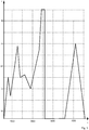
- Figures 2 and 3 show the current ratio I/I> varying in time T ( Figure 2 ) and the respective cumulation of the start duration value ( Figure 3 ) in accordance with the fluctuation of the current in Figure 2 . It has to be noted that the example situation depicted in Figure 2 corresponds to an ideal situation where the current levels change abruptly.
- the current ratio level "1" depicts a startup threshold level, that is a level where a state transition ACTING->PICKUP occurs in accordance with Figure 1 .
- Values greater than 1 depict the operate situation, where the equation 15 ratio value increases.
- operate periods thus occur in time intervals 0..610, 870..1550, 1770..2250 and change in the signal level at the moment 3670 ms.
- Values lower than 1 depict the reset situation where the startup counter value decreases.
- reset periods thus occur in time periods 610..870, 1550..1770, 2250..2800.
- the apparatus performs a state transition to PICKUP state and stays in the PICKUP state until 610 ms has elapsed, whereafter a state transition to DROPOFF state is performed.
- Figure 3 shows the value of the startup duration counter as a function of time in the situation of Figure 2 . It may be seen that the value of the startup duration increases during the operate periods, such as 0..610 ms, and decreases during the reset periods, such as 610..870 ms. The figure also shows that a trip condition occurs at a moment 3900 ms, when the startup counter value reaches 100% and the state machine goes to OPERATE state. When the current falls below the threshold value "1-hysteresis" (which has been 2% in this simulation) after reaching OPERATE, the device goes to ACTING state.
- the threshold value "1-hysteresis" which has been 2% in this simulation
- Figure 4 shows an embodiment of a method.
- the method may be implemented in an overcurrent relay applying an IDMT (Inverse Definite Minimum Timer) principle.
- IDMT Inverse Definite Minimum Timer
- the relay monitors the input current, and in 402, the input current is compared to a startup threshold of the relay protection function. If the outcome of the comparison indicates that the input current is greater than the threshold, the method proceeds to 406 where sumOfS and operCounter counters are incremented.
- the comparison 404 indicates that the input current is lower than the startup threshold minus the hysteresis value, the decOfS counter is incremented in 408.
- a check 412 is carried out whether the equation 15 nominator has gone down to 0.
- the device goes to ACTING state. After reaching OPERATE, when the input current undershoots the startup threshold minus the hysteresis next time, a state transition to ACTING state takes place. Alternatively, if reset is after OPERATE based on a reset equation, the method proceeds to ACTING when equation 15 nominator has gone down to 0.
- the counters processed in the method are arranged into a form, in which the checking of the operate condition may be carried out by a simple comparison of two measures.
- these two measures have been placed in the nominator and denominator.
- the denominator may be multiplied to the right-hand side of the equation, whereby again the tripping condition may be performed by means of a comparison of the two sides of the equation.
- Figure 5 shows a protection relay 500 showing only portions relevant to the disclosure.
- the relay includes an input port 502 for inputting a characteristic measure, such as current, voltage or frequency.
- the relay also includes a control unit 504 configured to control the operation of the device.
- the control unit may be implemented as a processor, and the functionalities may be implemented onto the processor by means of software, for instance.
- Figure 5 also shows a calculating 506 unit, which may update a calculation equation upon the input characteristic measure.
- the relay may also include a module 508 responsible for overflow management of the calculation equation.
- a memory 510 may also be provided for storing LUT table items for use by the calculation equation. Instead of having a separate memory for lookup tables, the values may also be calculated during execution. All these functionalities 506 to 510 may, instead of separate units, be implemented on the control unit, such as a processor.
- the device may also include an output unit 512 for providing an output signal. The output signal is dependent on the outcome of the result of the calculation equation. If, for instance, the calculation equation shows that a tripping or reset condition has been reached, the output unit provides the respective output signal.
- the reset functionality may be embedded in the implementation such that the accuracy of the calculation is kept good.
- the shown embodiments provide an accurate way to implement an inverse definite time operation to calculate the operation time from the equations themselves.
- the embodiments also provide a way to reduce computational complexity by avoiding divisions when making real time computations. The only calculation operations needed are multiplications, additions and subtractions.
Landscapes
- Emergency Protection Circuit Devices (AREA)
Claims (14)
- Verfahren zum Steuern eines Schutzrelais, umfassend;
Eingeben (400) einer Eingangskenngröße;
Bestimmen (402, 410, 414) einer Auslösebedingung für das Schutzrelais mittels einer Berechnungsgleichung, deren Wert zunimmt, wenn die Eingangskenngröße einen ersten Schwellenwert überschreitet, und abnimmt, wenn die Eingangskenngröße einen zweiten Schwellenwert für ein Überfunktionsmaß unterschreitet, und der Wert der Berechnungsgleichung zunimmt, wenn die Eingangskenngröße einen ersten Schwellenwert unterschreitet, und abnimmt, wenn die Eingangskenngröße einen zweiten Schwellenwert für ein Unterfunktionsmaß überschreitet, wobei die Berechnungsgleichung in Form einer Division eingerichtet ist und ein erstes Maß und ein zweites Maß enthält, wobei das erste Maß als Zähler der Division und das zweite Maß als Nenner der Division eingerichtet ist und das Auslösen erfolgt, wenn das erste Maß größer als das zweite Maß ist. - Verfahren nach Anspruch 1, wobei der zweite Schwellenwert durch Reduzieren einer Hystereseeinstellung vom ersten Schwellenwert für ein Überfunktionsmaß und durch Addieren einer Hystereseeinstellung zum ersten Schwellenwert für ein Unterfunktionsmaß erhalten wird, wobei der Bereich zwischen dem ersten Schwellenwert und dem zweiten Schwellenwert einen Hysteresebereich definiert, in dem die Berechnung der Berechnungsgleichung ausgesetzt wird.
- Verfahren nach Anspruch 1, wobei die Berechnungsgleichung einen oder mehrere kumulativ ansteigende Summenterme enthält, die unter einer vorbestimmten Bedingung erhöht werden, und ein vorbestimmter Maximalwert für den einen oder die mehreren Summenterme definiert wird, und wobei ein Summenterm durch einen Divisor geteilt wird, wenn der Summenterm den Maximalwert erreicht.
- Verfahren nach Anspruch 3, wobei die Summentermwerte in einer Nachschlagtabelle in vordefinierten Intervallen als Funktion des Kennmaßes indiziert werden und bei Erreichen des kumulativen Summenmaximalwertes der indizierte Nachschlagtabellensummenterm durch denselben Divisor wie die kumulative Summe selbst geteilt wird.
- Verfahren nach Anspruch 4, wobei sich der vorbestimmte Maximalwert zwischen verschiedenen Summentermen unterscheidet.
- Verfahren nach Anspruch 4, wobei sich die Intervalle zwischen den Indizes der Nachschlagtabelle stufenweise ändern, sodass sich mehr Indizes in einem abrupten Teil einer Kurve befinden, die die Summentermwerte als eine Funktion der Indizes darstellt.
- Verfahren nach Anspruch 1, ferner umfassend Überwachen einer oder mehrerer Variablen in der Berechnungsgleichung und Vergleichen des Wertes jeder der Variablen mit einem vorbestimmten Schwellenwert der Variablen und ähnliches Reduzieren jedes Terms in der Berechnungsgleichung, wenn eine Variable ihren Schwellenwert erreicht.
- Schutzrelais, umfassend:Mittel (502) zum Eingeben einer Eingangskenngröße;Mittel (506, 512) zum Bestimmen einer Auslösebedingung für das Schutzrelais mittels einer Berechnungsgleichung, die so eingerichtet ist, dass sie sich erhöht, wenn die Eingangskenngröße einen ersten Schwellenwert überschreitet, und sich verringert, wenn die Eingangskenngröße einen zweiten Schwellenwert für ein Überfunktionsmaß unterschreitet, und die Berechnungsgleichung so eingerichtet ist, dass sie sich erhöht, wenn die Eingangskenngröße einen ersten Schwellenwert unterschreitet, und sich verringert, wenn die Eingangskenngröße einen zweiten Schwellenwert für ein Unterfunktionsmaß überschreitet, wobei die Berechnungsgleichung in Form einer Division eingerichtet ist und ein erstes Maß und ein zweites Maß enthält, wobei das erste Maß in einen Zähler der Division und das zweite Maß in einen Nenner der Division eingerichtet ist und das Auslösen erfolgt, wenn das erste Maß größer als das zweite Maß ist.
- Schutzrelais nach Anspruch 8, wobei der zweite Schwellenwert durch Reduzieren einer Hystereseeinstellung vom ersten Schwellenwert für ein Überfunktionsmaß und durch Addieren einer Hystereseeinstellung zum ersten Schwellenwert für ein Unterfunktionsmaß erhalten wird, wobei der Bereich zwischen dem ersten Schwellenwert und dem zweiten Schwellenwert einen Hysteresebereich definiert, in dem das Berechnen der Berechnungsgleichung ausgesetzt wird.
- Schutzrelais nach Anspruch 8, wobei die Berechnungsgleichung einen oder mehrere kumulativ ansteigende Summenterme aufweist, die unter einer vorbestimmten Bedingung erhöht werden, und ein vorbestimmter Maximalwert für den einen oder die mehreren Summenterme definiert ist, und wobei ein Summenterm durch einen Divisor geteilt wird, wenn der Summenterm den Maximalwert erreicht.
- Schutzrelais nach Anspruch 10, wobei die Summentermwerte in einer Nachschlagtabelle in vordefinierten Intervallen als Funktion des Kennmaßes indiziert werden und bei Erreichen des kumulativen Summenmaximalwertes der indizierte Nachschlagtabellensummenterm durch denselben Divisor wie die kumulative Summe selbst geteilt wird.
- Schutzrelais nach Anspruch 10, wobei die vorbestimmten Maximalwerte sich zwischen verschiedenen Summentermen unterscheiden.
- Schutzrelais nach Anspruch 10, wobei sich die Intervalle zwischen den Indizes der Nachschlagtabelle stufenweise ändern, sodass sich mehr Indizes in einem abrupten Teil einer Kurve befinden, die die Summentermwerte als eine Funktion der Indizes darstellt.
- Schutzrelais nach Anspruch 8, wobei Überwachen einer oder mehrerer Variablen in der Berechnungsgleichung und Vergleichen des Wertes jeder der Variablen mit einem vorbestimmten Schwellenwert der Variablen und ähnliches Reduzieren jedes Terms in der Berechnungsgleichung wenn eine Variable ihren Schwellenwert erreicht.
Applications Claiming Priority (1)
| Application Number | Priority Date | Filing Date | Title |
|---|---|---|---|
| PCT/FI2007/050716 WO2009080865A1 (en) | 2007-12-20 | 2007-12-20 | Control of operation of protection relay |
Publications (3)
| Publication Number | Publication Date |
|---|---|
| EP2232659A1 EP2232659A1 (de) | 2010-09-29 |
| EP2232659A4 EP2232659A4 (de) | 2014-01-01 |
| EP2232659B1 true EP2232659B1 (de) | 2020-04-15 |
Family
ID=40800753
Family Applications (1)
| Application Number | Title | Priority Date | Filing Date |
|---|---|---|---|
| EP07858367.1A Active EP2232659B1 (de) | 2007-12-20 | 2007-12-20 | Steuerung des betriebs eines schutzrelais |
Country Status (4)
| Country | Link |
|---|---|
| US (1) | US8611060B2 (de) |
| EP (1) | EP2232659B1 (de) |
| CN (1) | CN101904072B (de) |
| WO (1) | WO2009080865A1 (de) |
Families Citing this family (5)
| Publication number | Priority date | Publication date | Assignee | Title |
|---|---|---|---|---|
| EP2501008B1 (de) | 2011-03-15 | 2020-02-19 | ABB Schweiz AG | Schutzrelais |
| DE102011052703B4 (de) * | 2011-08-15 | 2020-07-09 | Dr. Ing. H.C. F. Porsche Aktiengesellschaft | Steuergerät einer Niveauregelung und Niveauregulierungsanlage |
| US20140164995A1 (en) * | 2012-12-12 | 2014-06-12 | Nishant Ghadge | Graphical representation of threshold operations |
| CN107239373B (zh) * | 2017-05-23 | 2020-01-21 | 许继集团有限公司 | 一种嵌入式继电保护设备的仿真方法及系统 |
| CN112583243B (zh) * | 2020-12-04 | 2022-02-18 | 嘉兴丹那赫电子科技有限公司 | 一种用于变频器的硬件限流方法、装置及存储介质 |
Family Cites Families (6)
| Publication number | Priority date | Publication date | Assignee | Title |
|---|---|---|---|---|
| US4672501A (en) * | 1984-06-29 | 1987-06-09 | General Electric Company | Circuit breaker and protective relay unit |
| US5751532A (en) * | 1996-02-28 | 1998-05-12 | Basler Electric Company | Intergrating reset overcurrent relay |
| US5987393A (en) * | 1997-02-20 | 1999-11-16 | Abb Power T&D Company Inc. | Method of configuring a microprocessor-based relay for use in overcurrent protection |
| US6330141B1 (en) * | 2000-06-13 | 2001-12-11 | Eaton Corporation | Electronic protective relay with variable and fixed delay tally time of current protection |
| US7123457B2 (en) * | 2003-06-27 | 2006-10-17 | Schweitzer Engineering Laboratories, Inc. | System for transitioning to the trip threshold for the start condition thermal model for a motor protection relay |
| AU2006261890B2 (en) * | 2005-06-24 | 2010-06-10 | Schweitzer Engineering Laboratories, Inc. | Dynamically configurable relay element and related methods |
-
2007
- 2007-12-20 WO PCT/FI2007/050716 patent/WO2009080865A1/en not_active Ceased
- 2007-12-20 CN CN200780102044.3A patent/CN101904072B/zh active Active
- 2007-12-20 EP EP07858367.1A patent/EP2232659B1/de active Active
-
2010
- 2010-06-21 US US12/819,585 patent/US8611060B2/en active Active
Non-Patent Citations (1)
| Title |
|---|
| None * |
Also Published As
| Publication number | Publication date |
|---|---|
| WO2009080865A1 (en) | 2009-07-02 |
| CN101904072B (zh) | 2014-08-20 |
| EP2232659A1 (de) | 2010-09-29 |
| EP2232659A4 (de) | 2014-01-01 |
| US20100309596A1 (en) | 2010-12-09 |
| US8611060B2 (en) | 2013-12-17 |
| CN101904072A (zh) | 2010-12-01 |
Similar Documents
| Publication | Publication Date | Title |
|---|---|---|
| US6330141B1 (en) | Electronic protective relay with variable and fixed delay tally time of current protection | |
| US8611060B2 (en) | Control of operation of protection relay | |
| US4937757A (en) | Digital circuit interrupter with selectable trip parameters | |
| US7570469B2 (en) | Dynamically configurable relay element and related methods | |
| US20110295529A1 (en) | Control of protection relay | |
| JP3389570B2 (ja) | 引外し装置の即時保護方法 | |
| EP3345272B1 (de) | Breitbandstromüberwachungssystem und verfahren für elektronische auslöseeinheiten | |
| CN103219696B (zh) | 一种过流保护方法及装置 | |
| EP2501008B1 (de) | Schutzrelais | |
| CA2554118A1 (en) | Thermal overload protection | |
| EP3739605B1 (de) | Gesteuertes schalten eines leistungsschalters | |
| RU2459330C2 (ru) | Способ управления реле защиты и реле защиты | |
| EP1643607A2 (de) | Überstromauslösereinheit | |
| JP2005106616A5 (de) | ||
| EP0999629A1 (de) | Thermische Überlastschutzvorrichtung für einen Elektromotor und entsprechendes Verfahren | |
| JP7515354B2 (ja) | 系統安定化システムおよび系統安定化方法 | |
| CN119401485A (zh) | 机组的一次调频方法、装置、存储介质及电子设备 | |
| JP7479012B2 (ja) | 遮断システム、遮断器及び分電盤 | |
| JP2003329708A (ja) | 発信装置付電力量計 | |
| KR20240066728A (ko) | 부하전류를 이용한 동작치 자동 정정 기능을 갖는 과전류 계전기 및 그 동작 방법 | |
| JPH05108178A (ja) | 力率改善用コンデンサ投入遮断制御装置 | |
| JP2908636B2 (ja) | 交流安定化電源装置 | |
| CN118676936A (zh) | 一种基于线路负荷的调压装置智能开启系统及方法 | |
| JP2007312508A (ja) | ディジタル過電流保護継電器システム | |
| JPH0876807A (ja) | プロセス伝達関数同定装置 |
Legal Events
| Date | Code | Title | Description |
|---|---|---|---|
| PUAI | Public reference made under article 153(3) epc to a published international application that has entered the european phase |
Free format text: ORIGINAL CODE: 0009012 |
|
| 17P | Request for examination filed |
Effective date: 20100706 |
|
| AK | Designated contracting states |
Kind code of ref document: A1 Designated state(s): AT BE BG CH CY CZ DE DK EE ES FI FR GB GR HU IE IS IT LI LT LU LV MC MT NL PL PT RO SE SI SK TR |
|
| AX | Request for extension of the european patent |
Extension state: AL BA HR MK RS |
|
| DAX | Request for extension of the european patent (deleted) | ||
| A4 | Supplementary search report drawn up and despatched |
Effective date: 20131202 |
|
| RIC1 | Information provided on ipc code assigned before grant |
Ipc: H02H 1/04 20060101ALN20131126BHEP Ipc: H02H 3/093 20060101AFI20131126BHEP |
|
| 17Q | First examination report despatched |
Effective date: 20150512 |
|
| STAA | Information on the status of an ep patent application or granted ep patent |
Free format text: STATUS: EXAMINATION IS IN PROGRESS |
|
| RAP1 | Party data changed (applicant data changed or rights of an application transferred) |
Owner name: ABB SCHWEIZ AG |
|
| REG | Reference to a national code |
Ref country code: DE Ref legal event code: R079 Ref document number: 602007060112 Country of ref document: DE Free format text: PREVIOUS MAIN CLASS: H02H0003000000 Ipc: H02H0003093000 |
|
| GRAP | Despatch of communication of intention to grant a patent |
Free format text: ORIGINAL CODE: EPIDOSNIGR1 |
|
| STAA | Information on the status of an ep patent application or granted ep patent |
Free format text: STATUS: GRANT OF PATENT IS INTENDED |
|
| RIC1 | Information provided on ipc code assigned before grant |
Ipc: H02H 1/04 20060101ALN20191023BHEP Ipc: H02H 3/093 20060101AFI20191023BHEP |
|
| RIC1 | Information provided on ipc code assigned before grant |
Ipc: H02H 3/093 20060101AFI20191105BHEP Ipc: H02H 1/04 20060101ALN20191105BHEP |
|
| INTG | Intention to grant announced |
Effective date: 20191119 |
|
| GRAS | Grant fee paid |
Free format text: ORIGINAL CODE: EPIDOSNIGR3 |
|
| GRAA | (expected) grant |
Free format text: ORIGINAL CODE: 0009210 |
|
| STAA | Information on the status of an ep patent application or granted ep patent |
Free format text: STATUS: THE PATENT HAS BEEN GRANTED |
|
| RAP1 | Party data changed (applicant data changed or rights of an application transferred) |
Owner name: ABB SCHWEIZ AG |
|
| AK | Designated contracting states |
Kind code of ref document: B1 Designated state(s): AT BE BG CH CY CZ DE DK EE ES FI FR GB GR HU IE IS IT LI LT LU LV MC MT NL PL PT RO SE SI SK TR |
|
| REG | Reference to a national code |
Ref country code: GB Ref legal event code: FG4D Ref country code: CH Ref legal event code: EP |
|
| REG | Reference to a national code |
Ref country code: DE Ref legal event code: R096 Ref document number: 602007060112 Country of ref document: DE |
|
| REG | Reference to a national code |
Ref country code: IE Ref legal event code: FG4D |
|
| REG | Reference to a national code |
Ref country code: AT Ref legal event code: REF Ref document number: 1258413 Country of ref document: AT Kind code of ref document: T Effective date: 20200515 |
|
| REG | Reference to a national code |
Ref country code: FI Ref legal event code: FGE |
|
| REG | Reference to a national code |
Ref country code: NL Ref legal event code: MP Effective date: 20200415 |
|
| REG | Reference to a national code |
Ref country code: LT Ref legal event code: MG4D |
|
| PG25 | Lapsed in a contracting state [announced via postgrant information from national office to epo] |
Ref country code: PT Free format text: LAPSE BECAUSE OF FAILURE TO SUBMIT A TRANSLATION OF THE DESCRIPTION OR TO PAY THE FEE WITHIN THE PRESCRIBED TIME-LIMIT Effective date: 20200817 Ref country code: NL Free format text: LAPSE BECAUSE OF FAILURE TO SUBMIT A TRANSLATION OF THE DESCRIPTION OR TO PAY THE FEE WITHIN THE PRESCRIBED TIME-LIMIT Effective date: 20200415 Ref country code: LT Free format text: LAPSE BECAUSE OF FAILURE TO SUBMIT A TRANSLATION OF THE DESCRIPTION OR TO PAY THE FEE WITHIN THE PRESCRIBED TIME-LIMIT Effective date: 20200415 Ref country code: GR Free format text: LAPSE BECAUSE OF FAILURE TO SUBMIT A TRANSLATION OF THE DESCRIPTION OR TO PAY THE FEE WITHIN THE PRESCRIBED TIME-LIMIT Effective date: 20200716 Ref country code: SE Free format text: LAPSE BECAUSE OF FAILURE TO SUBMIT A TRANSLATION OF THE DESCRIPTION OR TO PAY THE FEE WITHIN THE PRESCRIBED TIME-LIMIT Effective date: 20200415 Ref country code: IS Free format text: LAPSE BECAUSE OF FAILURE TO SUBMIT A TRANSLATION OF THE DESCRIPTION OR TO PAY THE FEE WITHIN THE PRESCRIBED TIME-LIMIT Effective date: 20200815 |
|
| REG | Reference to a national code |
Ref country code: AT Ref legal event code: MK05 Ref document number: 1258413 Country of ref document: AT Kind code of ref document: T Effective date: 20200415 |
|
| PG25 | Lapsed in a contracting state [announced via postgrant information from national office to epo] |
Ref country code: BG Free format text: LAPSE BECAUSE OF FAILURE TO SUBMIT A TRANSLATION OF THE DESCRIPTION OR TO PAY THE FEE WITHIN THE PRESCRIBED TIME-LIMIT Effective date: 20200715 Ref country code: LV Free format text: LAPSE BECAUSE OF FAILURE TO SUBMIT A TRANSLATION OF THE DESCRIPTION OR TO PAY THE FEE WITHIN THE PRESCRIBED TIME-LIMIT Effective date: 20200415 |
|
| REG | Reference to a national code |
Ref country code: DE Ref legal event code: R097 Ref document number: 602007060112 Country of ref document: DE |
|
| PG25 | Lapsed in a contracting state [announced via postgrant information from national office to epo] |
Ref country code: RO Free format text: LAPSE BECAUSE OF FAILURE TO SUBMIT A TRANSLATION OF THE DESCRIPTION OR TO PAY THE FEE WITHIN THE PRESCRIBED TIME-LIMIT Effective date: 20200415 Ref country code: CZ Free format text: LAPSE BECAUSE OF FAILURE TO SUBMIT A TRANSLATION OF THE DESCRIPTION OR TO PAY THE FEE WITHIN THE PRESCRIBED TIME-LIMIT Effective date: 20200415 Ref country code: AT Free format text: LAPSE BECAUSE OF FAILURE TO SUBMIT A TRANSLATION OF THE DESCRIPTION OR TO PAY THE FEE WITHIN THE PRESCRIBED TIME-LIMIT Effective date: 20200415 Ref country code: ES Free format text: LAPSE BECAUSE OF FAILURE TO SUBMIT A TRANSLATION OF THE DESCRIPTION OR TO PAY THE FEE WITHIN THE PRESCRIBED TIME-LIMIT Effective date: 20200415 Ref country code: DK Free format text: LAPSE BECAUSE OF FAILURE TO SUBMIT A TRANSLATION OF THE DESCRIPTION OR TO PAY THE FEE WITHIN THE PRESCRIBED TIME-LIMIT Effective date: 20200415 Ref country code: EE Free format text: LAPSE BECAUSE OF FAILURE TO SUBMIT A TRANSLATION OF THE DESCRIPTION OR TO PAY THE FEE WITHIN THE PRESCRIBED TIME-LIMIT Effective date: 20200415 |
|
| PLBE | No opposition filed within time limit |
Free format text: ORIGINAL CODE: 0009261 |
|
| STAA | Information on the status of an ep patent application or granted ep patent |
Free format text: STATUS: NO OPPOSITION FILED WITHIN TIME LIMIT |
|
| PG25 | Lapsed in a contracting state [announced via postgrant information from national office to epo] |
Ref country code: SK Free format text: LAPSE BECAUSE OF FAILURE TO SUBMIT A TRANSLATION OF THE DESCRIPTION OR TO PAY THE FEE WITHIN THE PRESCRIBED TIME-LIMIT Effective date: 20200415 Ref country code: PL Free format text: LAPSE BECAUSE OF FAILURE TO SUBMIT A TRANSLATION OF THE DESCRIPTION OR TO PAY THE FEE WITHIN THE PRESCRIBED TIME-LIMIT Effective date: 20200415 |
|
| 26N | No opposition filed |
Effective date: 20210118 |
|
| PG25 | Lapsed in a contracting state [announced via postgrant information from national office to epo] |
Ref country code: SI Free format text: LAPSE BECAUSE OF FAILURE TO SUBMIT A TRANSLATION OF THE DESCRIPTION OR TO PAY THE FEE WITHIN THE PRESCRIBED TIME-LIMIT Effective date: 20200415 |
|
| REG | Reference to a national code |
Ref country code: CH Ref legal event code: PL |
|
| GBPC | Gb: european patent ceased through non-payment of renewal fee |
Effective date: 20201220 |
|
| PG25 | Lapsed in a contracting state [announced via postgrant information from national office to epo] |
Ref country code: MC Free format text: LAPSE BECAUSE OF FAILURE TO SUBMIT A TRANSLATION OF THE DESCRIPTION OR TO PAY THE FEE WITHIN THE PRESCRIBED TIME-LIMIT Effective date: 20200415 |
|
| REG | Reference to a national code |
Ref country code: BE Ref legal event code: MM Effective date: 20201231 |
|
| PG25 | Lapsed in a contracting state [announced via postgrant information from national office to epo] |
Ref country code: LU Free format text: LAPSE BECAUSE OF NON-PAYMENT OF DUE FEES Effective date: 20201220 Ref country code: IE Free format text: LAPSE BECAUSE OF NON-PAYMENT OF DUE FEES Effective date: 20201220 |
|
| PG25 | Lapsed in a contracting state [announced via postgrant information from national office to epo] |
Ref country code: CH Free format text: LAPSE BECAUSE OF NON-PAYMENT OF DUE FEES Effective date: 20201231 Ref country code: GB Free format text: LAPSE BECAUSE OF NON-PAYMENT OF DUE FEES Effective date: 20201220 Ref country code: LI Free format text: LAPSE BECAUSE OF NON-PAYMENT OF DUE FEES Effective date: 20201231 |
|
| PG25 | Lapsed in a contracting state [announced via postgrant information from national office to epo] |
Ref country code: TR Free format text: LAPSE BECAUSE OF FAILURE TO SUBMIT A TRANSLATION OF THE DESCRIPTION OR TO PAY THE FEE WITHIN THE PRESCRIBED TIME-LIMIT Effective date: 20200415 Ref country code: MT Free format text: LAPSE BECAUSE OF FAILURE TO SUBMIT A TRANSLATION OF THE DESCRIPTION OR TO PAY THE FEE WITHIN THE PRESCRIBED TIME-LIMIT Effective date: 20200415 Ref country code: CY Free format text: LAPSE BECAUSE OF FAILURE TO SUBMIT A TRANSLATION OF THE DESCRIPTION OR TO PAY THE FEE WITHIN THE PRESCRIBED TIME-LIMIT Effective date: 20200415 |
|
| PG25 | Lapsed in a contracting state [announced via postgrant information from national office to epo] |
Ref country code: BE Free format text: LAPSE BECAUSE OF NON-PAYMENT OF DUE FEES Effective date: 20201231 |
|
| PG25 | Lapsed in a contracting state [announced via postgrant information from national office to epo] |
Ref country code: IS Free format text: LAPSE BECAUSE OF NON-PAYMENT OF DUE FEES Effective date: 20200815 |
|
| PGFP | Annual fee paid to national office [announced via postgrant information from national office to epo] |
Ref country code: DE Payment date: 20251211 Year of fee payment: 19 |
|
| PGFP | Annual fee paid to national office [announced via postgrant information from national office to epo] |
Ref country code: IT Payment date: 20251223 Year of fee payment: 19 Ref country code: FI Payment date: 20251223 Year of fee payment: 19 |
|
| PGFP | Annual fee paid to national office [announced via postgrant information from national office to epo] |
Ref country code: FR Payment date: 20251222 Year of fee payment: 19 |