EP2232659B1 - Control of operation of protection relay - Google Patents
Control of operation of protection relay Download PDFInfo
- Publication number
- EP2232659B1 EP2232659B1 EP07858367.1A EP07858367A EP2232659B1 EP 2232659 B1 EP2232659 B1 EP 2232659B1 EP 07858367 A EP07858367 A EP 07858367A EP 2232659 B1 EP2232659 B1 EP 2232659B1
- Authority
- EP
- European Patent Office
- Prior art keywords
- threshold value
- measure
- value
- sum
- equation
- Prior art date
- Legal status (The legal status is an assumption and is not a legal conclusion. Google has not performed a legal analysis and makes no representation as to the accuracy of the status listed.)
- Active
Links
Images



Classifications
-
- H—ELECTRICITY
- H02—GENERATION; CONVERSION OR DISTRIBUTION OF ELECTRIC POWER
- H02H—EMERGENCY PROTECTIVE CIRCUIT ARRANGEMENTS
- H02H3/00—Emergency protective circuit arrangements for automatic disconnection directly responsive to an undesired change from normal electric working condition with or without subsequent reconnection ; integrated protection
- H02H3/08—Emergency protective circuit arrangements for automatic disconnection directly responsive to an undesired change from normal electric working condition with or without subsequent reconnection ; integrated protection responsive to excess current
- H02H3/093—Emergency protective circuit arrangements for automatic disconnection directly responsive to an undesired change from normal electric working condition with or without subsequent reconnection ; integrated protection responsive to excess current with timing means
- H02H3/0935—Emergency protective circuit arrangements for automatic disconnection directly responsive to an undesired change from normal electric working condition with or without subsequent reconnection ; integrated protection responsive to excess current with timing means the timing being determined by numerical means
-
- H—ELECTRICITY
- H02—GENERATION; CONVERSION OR DISTRIBUTION OF ELECTRIC POWER
- H02H—EMERGENCY PROTECTIVE CIRCUIT ARRANGEMENTS
- H02H1/00—Details of emergency protective circuit arrangements
- H02H1/04—Arrangements for preventing response to transient abnormal conditions, e.g. to lightning or to short duration over voltage or oscillations; Damping the influence of DC component by short circuits in AC networks
Definitions
- the present invention relates to control of a protection relay and more particularly to control of a protection relay operating in an electric network.
- Relays are used in protection of electric networks and devices, for instance.
- Relay protection functions may be implemented as constant-time functions, where the operation time is independent of the value of the characteristic measure, such as current, voltage or frequency.
- relay protection functions may be inverse-time dependent, when the operation time is inversely dependent on the magnitude of the measured signal.
- the inverse-time based algorithm analysis is typically based on the assumption that the current or overcurrent exceeding a set current threshold value or undercurrent undershooting a set current threshold value is constant during the measurement time. This results in a simple analogy between theoretical calculations and implementation. However, in practice fluctuation and variation in the characteristic measure magnitude level result in a realized operation time of the device.
- US 4,672,501 discloses a protective relay for continuously monitoring the electrical status of a protected power distribution system.
- the ROM and RAM storage elements within the processor are continuously tested and the circuit breaker contacts are opened upon indication that the ROM or RAM element is non-functional.
- US 5,987,393 discloses a system for generating a time overcurrent curve from a set of time and current inputs.
- the overcurrent curve is generated by simultaneously finding four coefficients of a standard overcurrent equation.
- US 6,330,141 discloses an electronic protective relay emulating an electromechanical protective relay so that operation of the two types of relays can be coordinated in providing protection in an electric power distribution network.
- US 2006/0291120 discloses a dynamically configurable relay element configured to protect an electrical system.
- An object of the present invention is thus to provide a method and an apparatus for implementing the method so as to alleviate the above disadvantages.
- Figure 1 shows an embodiment of a state diagram of a protection relay.
- the protection relay inputs a characteristic quantity, upon which operation decisions and different functionalities may be carried out in the protection relay.
- the characteristic quantity is current, but may as well be some other measure, such as voltage, frequency, or temperature, for instance.
- the invention is explained in respect of an overcurrent relay that is the overfunction is overcurrent.
- the invention may as well be applied to an underfunction relay such as an undercurrent relay, in which case the operation is reverse to what is explained in the following.
- INITIAL state the device is not yet in use.
- state ACTING the device is measuring the characteristic quantity, on which the operation of the device is dependent. If the relay is responsive to an over function measure, such as overcurrent, the device will react on a current exceeding a threshold value of the current.
- An example of a relay responsive to an under function measure is an undercurrent relay, which will react on current undershooting a threshold value.
- a state transition "2" from state ACTING to PICKUP depicts the situation where the current level exceeds a startup threshold value.
- state transitions "3" and "4" the device is kept in PICKUP state.
- the nominator of equation 15 is increased but the nominator value does not yet exceed the denominator value.
- the value of the input variable is higher than the start-up threshold value.
- a hysteresis region may be introduced around the startup threshold value, preventing unnecessary state transitions due to a current that oscillates around the startup threshold value. For overfunction, the hysteresis widens the signal range downwards, while for under function upwards.
- the state transition "4" describes a situation where the current is in the hysteresis region, which may be e.g. 2% under the startup threshold value, for instance, if 2% hysteresis has been set.
- the hysteresis region may extend to both sides of the startup threshold, which in the above example would give a +/- 2% region.
- the hysteresis setting may be a factory setting value, which may be determined based upon the transformer measurement inaccuracy etc. In an ideal case, from a pure algorithm point of view, hysteresis may even be set to zero but in practice it may be set to a value above zero. During this time, the equation 15 ratio is freezed, that is it is neither increased nor decreased.
- the state is changed to ACTING as indicated by arrow "7".
- a different hysteresis value than that used in PICKUP state may be used in OPERATE state to reset the operation back to ACTING.
- a reset type equation may be used to this. In this case, state RESET_OPERATE is first reached with a state transition "12" and then the reset equation is followed, which gradually decreases the equation 15 nominator to zero, causing the state change RESET_OPERATE->ACTING shown by arrow "13".
- DROPOFF state may be reached from PICKUP state when the current falls under the threshold minus the hysteresis value as indicated by arrow "8".
- the first transition “9” describes the situation where the input signal lies in the hysteresis region with the result that the calculation of the nominator/denominator of equation 15 is freezed, while the opposite state transition “14" follows if the signal magnitude exceeds the startup threshold value again.
- the state transition "10” describes the situation, where the input value is below the startup threshold value and outside the hysteresis region with the result that the equation 15 ratio value is being decreased while in this state.
- the operation equation (1) and the reset equation (5) also introduced by standards. They are dependent on the signal, that is the characteristic measure quantity, so that the operate equation is only valid for signal magnitude ratios (I versus I>) above the startup threshold value, while the reset equation is only valid for signal magnitude ratios below the startup threshold value.
- the upper limit of the operate equation depends on the transformer dynamic measurement accuracy without saturation while the lower limit of the reset equation is zero. Because the hysteresis region creates a natural 'gray region' between the operating regions, only one of the equations is valid at a time.
- Operation time denotes the time that has elapsed since the current exceeded the startup threshold value and the device thus performed a state transition to PICKUP state.
- Delay compensation denotes a system delay, which is a fully implementational delay when the operation of the device actually starts as calculated from an order to do so. In that case it compensates the measurement delay.
- Another delay that might be included in this same variable is an output relay delay that might also be compensated by shortening the calculating operate time.
- An aspect regarding the delay compensation is that this parameter remains constant during execution.
- equation (4) the relation between I and I > (that is "current ratio") is integrated over time.
- the integration may be carried out in n successive execution intervals. Thereby the fluctuation of the current may be taken into account effectively.
- Equation (4) now shows the incrementation aspect of the cumulative counter corresponding to the state transition 3 in Figure 1 .
- the incrementative counter is in operation when the current is above the startup threshold.
- the operate condition of an overcurrent protection function may be defined by a term called "start duration", which is a variable that indicates how far from operating the device is at a specific time instant. For example, if the curve operate time calculated from equation (1) has been found to be 1 second for a constant input signal, then starting with this particular input signal magnitude level, after half a second the "start duration" has a value of 50% and after 0.75 seconds its value will be 75%. Consequently, “start duration” runs from 0% to 100%, whereby at 0% the device is reset, and at 100% the device is configured to operate.
- the variable "start duration" thus aims to indicate how close to operating the device is if the same constant signal level remains. However, due to signal fluctuation this estimate cannot necessarily be realized.
- start duration (integrated operate time - integrated reset time) / total operate time.
- start duration (integrated operate time - integrated reset time) / total operate time.
- the integrated operate time of equations (1) to (4) and the integrated reset time of equation (5) may be combined to a single counter as follows.
- equation (1) can be written as t I ⁇ k ⁇ a M p ⁇ c + k ⁇ b .
- the integral cumulative sum ⁇ ( M p -c ) may be defined as sumOfS. These values may be either precalculated with predefined current ratio precision to an operate look-up-table so that it is a function of M or they may be calculated with a more precise current ratio value during the execution if sufficient computer power is available.
- resetCounter (equivalent to an operCounter parameter in the operate equation) so that actually, the equation will be (13), where resetCounter may be eliminated.
- startDuration int egTime 1 int egTime 2 ⁇ decOfS resetMult ⁇ 100 ⁇ % .
- a "start duration” counter is in a form having a term in parentheses multiplied by 100%.
- the tripping condition for a state transition to the OPERATE state is at 100% and is reached when the term in the parentheses equals 1.
- the division in equation (15) is not calculated but the tripping (operating) condition occurs when the nominator value exceeds the denominator value in equation 15.
- a state transition DROPOFF->ACTING state takes place when the nominator decreases to the value zero.
- This same equation may also be used for curves, for which some other type of reset equation than an equation-based reset has been chosen. This simplifies the calculation, when many equation terms can be replaced by constants. For example, decOfS has the value zero, causing the second term of the nominator to be zero. Note also that in that particular case, the term re setMult both in the nominator and the denominator may be eliminated.
- the delay compensation may be omitted in the reset condition calculation.
- Equation 16 the overflow management of Equation 16 is explained.
- the denominator is made smaller.
- One way to do this is to divide both equation sides by resetMult or some other corresponding divisor.
- parameter value range is specified already in productization phase and, thus, it is possible to certify already before hand that these execution phase fixed values are restricted However, it is possible to use a similar approach like told below with sumOfS and decOfS restriction, if needed, to restrict also AperTR and BperTr.
- Eq. 18 the overflow of the cumulative sums, i.e. sumOfS and decOfS may be investigated.
- Another non-fixed parameter during execution in the equation (Eq. 18) is operCounter, because the parameters timeShift, curveDelay and curveMult may be fixed during execution.
- an overflow limit to be smaller than log 2 (cumulative sum) and the maximum allowed LUT-insertion value is then difference between 2 selectedBitLength and the overflow limit.
- parameters p and c maximum value may be selected so that the maximum LUT-value is also restricted. For calculation accuracy point of view it may be feasible to use more fragment bit to LUT-item that is later used in cumulative sum.
- the highest possible LUT item and the cumulative sum limit for both operate and reset equation parts may be defined. If, in the operate equation part, the sumOfS is increases over the overflow limit, the sumOfS may be divided by a divisor N .
- the divisor N may be any number but preferably a multiple of 2, such as 2, 4, 8, etc. resulting simple bit-shift in implementation. Then, in the equation the previous sumOfS may be replaced by sumOfS / N.
- the new sumOfS may be sumOfS / ( N + N ) when compared to the original equation value. Then, the inserted LUT value will be LUT item / ( N + N ), accordingly. By this way, overflow may be avoided.
- decOfS may be replaced by decOfS / L, where a good choice for L is also 2, and the next good alternatives are 4, 8 etc. L may also equal N . In this case, Eq.
- startDuration 100 ⁇ % ⁇ ( operCounter ⁇ sumOfS ⁇ 1 / L + timeShift ⁇ sumOfS ⁇ 1 / L ⁇ sumOfS ⁇ curveDelay ⁇ 1 / L + decOfS ⁇ sumOfS ⁇ BperTR ⁇ decOfS ⁇ operCounter ⁇ AperTR operCounter ⁇ curveMult ⁇ 1 / L )
- the inserted LUT values may also be divided by L, L + L etc.
- startDuration 100 ⁇ % ⁇ ( operCounter ⁇ sumOfS ⁇ 1 / L + timeShift ⁇ sumOfS ⁇ 1 / L ⁇ sumOfS ⁇ curveDelay ⁇ 1 / L + decOfS ⁇ sumOfS ⁇ BperTR ⁇ decOfS ⁇ operCounter ⁇ AperTR ⁇ 1 / N operCounter ⁇ curveMult ⁇ 1 / N ⁇ L )
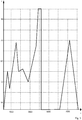
- Figures 2 and 3 show the current ratio I/I> varying in time T ( Figure 2 ) and the respective cumulation of the start duration value ( Figure 3 ) in accordance with the fluctuation of the current in Figure 2 . It has to be noted that the example situation depicted in Figure 2 corresponds to an ideal situation where the current levels change abruptly.
- the current ratio level "1" depicts a startup threshold level, that is a level where a state transition ACTING->PICKUP occurs in accordance with Figure 1 .
- Values greater than 1 depict the operate situation, where the equation 15 ratio value increases.
- operate periods thus occur in time intervals 0..610, 870..1550, 1770..2250 and change in the signal level at the moment 3670 ms.
- Values lower than 1 depict the reset situation where the startup counter value decreases.
- reset periods thus occur in time periods 610..870, 1550..1770, 2250..2800.
- the apparatus performs a state transition to PICKUP state and stays in the PICKUP state until 610 ms has elapsed, whereafter a state transition to DROPOFF state is performed.
- Figure 3 shows the value of the startup duration counter as a function of time in the situation of Figure 2 . It may be seen that the value of the startup duration increases during the operate periods, such as 0..610 ms, and decreases during the reset periods, such as 610..870 ms. The figure also shows that a trip condition occurs at a moment 3900 ms, when the startup counter value reaches 100% and the state machine goes to OPERATE state. When the current falls below the threshold value "1-hysteresis" (which has been 2% in this simulation) after reaching OPERATE, the device goes to ACTING state.
- the threshold value "1-hysteresis" which has been 2% in this simulation
- Figure 4 shows an embodiment of a method.
- the method may be implemented in an overcurrent relay applying an IDMT (Inverse Definite Minimum Timer) principle.
- IDMT Inverse Definite Minimum Timer
- the relay monitors the input current, and in 402, the input current is compared to a startup threshold of the relay protection function. If the outcome of the comparison indicates that the input current is greater than the threshold, the method proceeds to 406 where sumOfS and operCounter counters are incremented.
- the comparison 404 indicates that the input current is lower than the startup threshold minus the hysteresis value, the decOfS counter is incremented in 408.
- a check 412 is carried out whether the equation 15 nominator has gone down to 0.
- the device goes to ACTING state. After reaching OPERATE, when the input current undershoots the startup threshold minus the hysteresis next time, a state transition to ACTING state takes place. Alternatively, if reset is after OPERATE based on a reset equation, the method proceeds to ACTING when equation 15 nominator has gone down to 0.
- the counters processed in the method are arranged into a form, in which the checking of the operate condition may be carried out by a simple comparison of two measures.
- these two measures have been placed in the nominator and denominator.
- the denominator may be multiplied to the right-hand side of the equation, whereby again the tripping condition may be performed by means of a comparison of the two sides of the equation.
- Figure 5 shows a protection relay 500 showing only portions relevant to the disclosure.
- the relay includes an input port 502 for inputting a characteristic measure, such as current, voltage or frequency.
- the relay also includes a control unit 504 configured to control the operation of the device.
- the control unit may be implemented as a processor, and the functionalities may be implemented onto the processor by means of software, for instance.
- Figure 5 also shows a calculating 506 unit, which may update a calculation equation upon the input characteristic measure.
- the relay may also include a module 508 responsible for overflow management of the calculation equation.
- a memory 510 may also be provided for storing LUT table items for use by the calculation equation. Instead of having a separate memory for lookup tables, the values may also be calculated during execution. All these functionalities 506 to 510 may, instead of separate units, be implemented on the control unit, such as a processor.
- the device may also include an output unit 512 for providing an output signal. The output signal is dependent on the outcome of the result of the calculation equation. If, for instance, the calculation equation shows that a tripping or reset condition has been reached, the output unit provides the respective output signal.
- the reset functionality may be embedded in the implementation such that the accuracy of the calculation is kept good.
- the shown embodiments provide an accurate way to implement an inverse definite time operation to calculate the operation time from the equations themselves.
- the embodiments also provide a way to reduce computational complexity by avoiding divisions when making real time computations. The only calculation operations needed are multiplications, additions and subtractions.
Landscapes
- Emergency Protection Circuit Devices (AREA)
Description
- The present invention relates to control of a protection relay and more particularly to control of a protection relay operating in an electric network.
- Relays are used in protection of electric networks and devices, for instance. Relay protection functions may be implemented as constant-time functions, where the operation time is independent of the value of the characteristic measure, such as current, voltage or frequency. Alternatively, relay protection functions may be inverse-time dependent, when the operation time is inversely dependent on the magnitude of the measured signal.
- The inverse-time based algorithm analysis is typically based on the assumption that the current or overcurrent exceeding a set current threshold value or undercurrent undershooting a set current threshold value is constant during the measurement time. This results in a simple analogy between theoretical calculations and implementation. However, in practice fluctuation and variation in the characteristic measure magnitude level result in a realized operation time of the device.
-
US 4,672,501 discloses a protective relay for continuously monitoring the electrical status of a protected power distribution system. The ROM and RAM storage elements within the processor are continuously tested and the circuit breaker contacts are opened upon indication that the ROM or RAM element is non-functional. -
US 5,987,393 discloses a system for generating a time overcurrent curve from a set of time and current inputs. The overcurrent curve is generated by simultaneously finding four coefficients of a standard overcurrent equation. -
US 6,330,141 discloses an electronic protective relay emulating an electromechanical protective relay so that operation of the two types of relays can be coordinated in providing protection in an electric power distribution network. -
US 2006/0291120 discloses a dynamically configurable relay element configured to protect an electrical system. - An object of the present invention is thus to provide a method and an apparatus for implementing the method so as to alleviate the above disadvantages.
- The present invention is further defined in the appended claims.
- In the following the invention will be described in greater detail by means of preferred embodiments with reference to the attached drawings, in which
-
Figure 1 shows a state diagram of an electronic device; -
Figure 2 shows another state diagram of an electronic device; -
Figure 3 shows an example of dependence of the signal magnitude on time; -
Figure 4 shows an embodiment of a method; and -
Figure 5 shows an embodiment of an apparatus. -
Figure 1 shows an embodiment of a state diagram of a protection relay. The protection relay inputs a characteristic quantity, upon which operation decisions and different functionalities may be carried out in the protection relay. In the following figures and description, the characteristic quantity is current, but may as well be some other measure, such as voltage, frequency, or temperature, for instance. In the following, the invention is explained in respect of an overcurrent relay that is the overfunction is overcurrent. The invention may as well be applied to an underfunction relay such as an undercurrent relay, in which case the operation is reverse to what is explained in the following. - In the simplified state diagram of
Figure 1 , four states have been depicted. In INITIAL state, the device is not yet in use. When the device is taken into use, that is coupled to the system to be used, a state transition "1" to state ACTING is carried out. In state ACTING, the device is measuring the characteristic quantity, on which the operation of the device is dependent. If the relay is responsive to an over function measure, such as overcurrent, the device will react on a current exceeding a threshold value of the current. An example of a relay responsive to an under function measure is an undercurrent relay, which will react on current undershooting a threshold value. - A state transition "2" from state ACTING to PICKUP depicts the situation where the current level exceeds a startup threshold value. In state transitions "3" and "4", the device is kept in PICKUP state. In "3", the nominator of equation 15 is increased but the nominator value does not yet exceed the denominator value. During this state transition, the value of the input variable is higher than the start-up threshold value.
- A hysteresis region may be introduced around the startup threshold value, preventing unnecessary state transitions due to a current that oscillates around the startup threshold value. For overfunction, the hysteresis widens the signal range downwards, while for under function upwards. The state transition "4" describes a situation where the current is in the hysteresis region, which may be e.g. 2% under the startup threshold value, for instance, if 2% hysteresis has been set. Alternatively, the hysteresis region may extend to both sides of the startup threshold, which in the above example would give a +/- 2% region.
- The hysteresis setting may be a factory setting value, which may be determined based upon the transformer measurement inaccuracy etc. In an ideal case, from a pure algorithm point of view, hysteresis may even be set to zero but in practice it may be set to a value above zero. During this time, the equation 15 ratio is freezed, that is it is neither increased nor decreased.
- When the equation 15 nominator value finally exceeds the same equation denominator value, a state transition "5" PICKUP->OPERATE is executed. State OPERATE is kept as shown by arrow "6", while the signal stays above the startup threshold minus the hysteresis value.
- If the input signal value drops below the startup threshold value minus the hysteresis value, the state is changed to ACTING as indicated by arrow "7". Alternatively, a different hysteresis value than that used in PICKUP state may be used in OPERATE state to reset the operation back to ACTING. In another embodiment, a reset type equation may be used to this. In this case, state RESET_OPERATE is first reached with a state transition "12" and then the reset equation is followed, which gradually decreases the equation 15 nominator to zero, causing the state change RESET_OPERATE->ACTING shown by arrow "13".
- DROPOFF state may be reached from PICKUP state when the current falls under the threshold minus the hysteresis value as indicated by arrow "8".
- In DROPOFF state, two
internal state transitions 9 and 10 and thethird transition 14 are introduced. The first transition "9" describes the situation where the input signal lies in the hysteresis region with the result that the calculation of the nominator/denominator of equation 15 is freezed, while the opposite state transition "14" follows if the signal magnitude exceeds the startup threshold value again. The state transition "10" describes the situation, where the input value is below the startup threshold value and outside the hysteresis region with the result that the equation 15 ratio value is being decreased while in this state. - If the equation 15 nominator value reaches 0, the device is reset with the result that the device returns to state ACTING.
- In the following, the operation is explained mathematically. We may define two separate equations for current relays: the operation equation (1) and the reset equation (5), also introduced by standards. They are dependent on the signal, that is the characteristic measure quantity, so that the operate equation is only valid for signal magnitude ratios (I versus I>) above the startup threshold value, while the reset equation is only valid for signal magnitude ratios below the startup threshold value. The upper limit of the operate equation depends on the transformer dynamic measurement accuracy without saturation while the lower limit of the reset equation is zero. Because the hysteresis region creates a natural 'gray region' between the operating regions, only one of the equations is valid at a time. We are starting with the incrementation aspects of the final equation 15, i.e. explaining how the operate equation is constructed.
- The operation equation of an overcurrent relay has the basic form of (1):

- t(I) gives the operate time in seconds
- k is a settable time multiplier of the function
- a,b,p,c are curve parameters
- I is the measured current input to the equation
- I > is the startup threshold value of the current settable by a user.
- Equation (1) may be written in form (2)

- Here we can see that the operation time, that is the time in which to reach OPERATE state with the assumption of a constant input signal magnitude, is inversely dependent on current I. Thus, the greater the current is, the shorter the time t to the operation of the relay is. Curves may be drawn having different parameters in this equation. Such curves may be drawn as a function of constant signal magnitude ratio. However, in practice, the current may fluctuate in time, resulting to a curve implementation with successive integrations.
- Equation (2) may be written in form (3):

- OT
- is the operation time, and
- delayC
- is delay compensation.
- Operation time denotes the time that has elapsed since the current exceeded the startup threshold value and the device thus performed a state transition to PICKUP state. Delay compensation denotes a system delay, which is a fully implementational delay when the operation of the device actually starts as calculated from an order to do so. In that case it compensates the measurement delay. Another delay that might be included in this same variable is an output relay delay that might also be compensated by shortening the calculating operate time. An aspect regarding the delay compensation is that this parameter remains constant during execution.
- When taking into account that the calculation contains several successive integrations, equation (3) may be written as (4)

- n
- is the number of successive execution intervals.
- In equation (4), the relation between I and I> (that is "current ratio") is integrated over time. The integration may be carried out in n successive execution intervals. Thereby the fluctuation of the current may be taken into account effectively.
- Equation (4) now shows the incrementation aspect of the cumulative counter corresponding to the state transition 3 in
Figure 1 . The incrementative counter is in operation when the current is above the startup threshold. - However, during periods when the current is below the starting threshold setting minus hysteresis, the equation 15 nominator decreases as shown by the
internal state transition 10 inFigure 1 . This type of decreasing function, reset function, may be written in form
- t(I) gives the reset time in seconds
- k is a settable time multiplier of the function (the same that is used for operate time calculation)
- tr, pr, cr are curve parameters
- I is the measured current inputted to the equation
- I > is a settable startup threshold value of the current.
- The operate condition of an overcurrent protection function may be defined by a term called "start duration", which is a variable that indicates how far from operating the device is at a specific time instant. For example, if the curve operate time calculated from equation (1) has been found to be 1 second for a constant input signal, then starting with this particular input signal magnitude level, after half a second the "start duration" has a value of 50% and after 0.75 seconds its value will be 75%. Consequently, "start duration" runs from 0% to 100%, whereby at 0% the device is reset, and at 100% the device is configured to operate. The variable "start duration" thus aims to indicate how close to operating the device is if the same constant signal level remains. However, due to signal fluctuation this estimate cannot necessarily be realized. Also, drop-off periods during the operation lengthen the operate time, so that actually the definition of "start duration" may be extended to also include drop-off periods. Then the start duration may be defined as: Start duration = (integrated operate time - integrated reset time) / total operate time. Thus, the state transition DROPOFF->ACTING may take place when the "integrated operate time" minus "integrated reset time" => 0 and PICKUP->OPERATE takes place when (integrated operate time - integrated reset time) = total operate time. On the basis of this condition it may be found out that, while the total operate time in this context is a linear function, the nominator (integrated operate time - integrated reset time) as a derivative of the operate and reset equations has exponentially increasing characteristics, which can be seen in the following.
- The integrated operate time of equations (1) to (4) and the integrated reset time of equation (5) may be combined to a single counter as follows.
- When the current ratio (I/I>) is abbreviated as M, equation (1) can be written as

- Equation (6) may be written, by writing n => operCounter and including a taskTime (this is a synonym of the previously mentioned execution time/cycle) concept into the equation we will get operation inequality (7)

- By defining timeShift => delayC * 1000/taskTime, k*b*1/taskTime => curveDelay and k*a*1/taskTime => curveMult, we get (8):

- Furthermore, the integral cumulative sum Σ(Mp-c) may be defined as sumOfS. These values may be either precalculated with predefined current ratio precision to an operate look-up-table so that it is a function of M or they may be calculated with a more precise current ratio value during the execution if sufficient computer power is available. Finally we obtain (9):

- This is a so-called operate counter equation, where the left-hand side parameter is defined as integTime1 and the right-hand side parameter as integTime2 (these terms refer to the manner they have been calculated, i.e. by integrating the successive terms) so that

- and

- With regard to the reset equation, by beginning from (5) and defining similarly with sumOfS another look-up-table item (reset LUT) or calculating directly during the execution a cumulative sum called decOfS ≡ Σ(Mpr-cr) and k*tr*1/taskTime => resetMult, this leads to reset inequality (12):

- There can also be a so-called resetCounter parameter (equivalent to an operCounter parameter in the operate equation) so that actually, the equation will be (13), where resetCounter may be eliminated.

- Now both factors of the "start duration" definition have been calculated in order to show the operate condition. As a result, a combined counter equation is obtained by combining both operate and reset counter equations as the same equation. Eventually, the start duration value in two counter systems can be calculated as

- This expands to be

- Here, it can now be seen that the operate counter and the reset counter have been combined to a single counter, a "start duration" counter. This "start duration" counter is in a form having a term in parentheses multiplied by 100%. As a result, the tripping condition for a state transition to the OPERATE state is at 100% and is reached when the term in the parentheses equals 1. However, as already explained previously, the division in equation (15) is not calculated but the tripping (operating) condition occurs when the nominator value exceeds the denominator value in equation 15. Respectively, a state transition DROPOFF->ACTING state takes place when the nominator decreases to the value zero.
- This same equation may also be used for curves, for which some other type of reset equation than an equation-based reset has been chosen. This simplifies the calculation, when many equation terms can be replaced by constants. For example, decOfS has the value zero, causing the second term of the nominator to be zero. Note also that in that particular case, the term resetMult both in the nominator and the denominator may be eliminated.
- Another aspect that may be taken into account here is the delay compensation regarding the drop-off timer. If Eq. 7 and Eq. 13 are compared, it may be seen that the delay compensation does not affect the reset operation and thus resetCounter could be eliminated from the equation. In fact, the delay compensation may also affect the reset counter operation by shortening the reset time so that the actual start output may be deactivated at a correct time. However, this would mean that we should end the reset period calculation before the function itself has seen that the drop-off period has delayed for a set reset time, and this is not allowed. Thus, in an embodiment, the delay compensation may be omitted in the reset condition calculation.
- In the following, the variables used in the equations are summarized:
- operCounter is a cumulative tick counter for pick-up function
- timeShift is delayC * 1000/taskTime (where delayC may be given in seconds). This represents a fixed value during the pick-up operation.
- curveMult is k*a*1/taskTime. This represents a fixed value during the pick-up operation.
- curveDelay is k*b*1/taskTime. This represents a fixed value during the pick-up operation.
- resetMult is k*tr*1/taskTime. This represents a fixed value during the pick-up operation.
- sumOfS is Σ(Mp-c). These values may have been stored in a look-up table (LUT) beforehand. This LUT is called operate-LUT in the following.
- decOfS is Σ(Mpr-cr). These values may have been stored in a look-up table beforehand. This LUT is called reset-LUT in the following.
- Equation 15 may be written out to give

- In the following, the overflow management of Equation 16 is explained. In a first embodiment, the denominator is made smaller. One way to do this is to divide both equation sides by resetMult or some other corresponding divisor. After dividing both sides by resetMult, Eq. 16 may be written:

- If the variable curveDelay/resetMult is replaced by BperTR and curveMult/resetMult is replaced by AperTR, the equation may be written as

- A special case, where tr has the value zero, cannot be used to avoid division by zero. The parameter tr value zero actually means an immediate reset equation and consequently, the latter part of eq. 14 will be zero, and as a result, eq. 14 can be given in a more simple form

- Equation expansion gives then

- When comparing this equation to Eq. 15, it may be seen that instead of setting resetMult to zero (implying tr to be zero), resetMult has been set to unity. Another question is, if AperTR and BperTr can have too high values when resetMult has been set to a very low value. Actually, highest AperTR and BperTr results when resetMult has its minimum. For very small tr values in Eq. 18, either a and b may be restricted, or alternatively the lowest value of tr or all these three parameters may be restricted. Typically parameter value range is specified already in productization phase and, thus, it is possible to certify already before hand that these execution phase fixed values are restricted However, it is possible to use a similar approach like told below with sumOfS and decOfS restriction, if needed, to restrict also AperTR and BperTr.
- In Eq. 18, the overflow of the cumulative sums, i.e. sumOfS and decOfS may be investigated. Another non-fixed parameter during execution in the equation (Eq. 18) is operCounter, because the parameters timeShift, curveDelay and curveMult may be fixed during execution.
- In the following, an embodiment of a process for determining a limit value to the cumulative operate sum is described. The process itself is the same for the cumulative reset sum, too. At first, the LUT item content is investigated in order to find the maximum item value to be inserted to the cumulative sum sumOfS. Operate LUT-equation (and item content) is Mp-c, and its fixed point representation depends on the selected integer and fragment bit lengths, where selected bit length is a sum between the integer and fragment bit lengths. An operate overflow limit may then be calculated by solving inequality log2(cumulative sum + maximum item value) ≤ selected bit length for cumulative sum. Now we may select an overflow limit to be smaller than log2(cumulative sum) and the maximum allowed LUT-insertion value is then difference between 2selectedBitLength and the overflow limit. Similarly, for user programmable curves, parameters p and c maximum value may be selected so that the maximum LUT-value is also restricted. For calculation accuracy point of view it may be feasible to use more fragment bit to LUT-item that is later used in cumulative sum.
- In Eq. 18 there is the multiplication sumOfS*decOfS*BperTR. If cumulative sum bit length is assumed to be 28, a 64-bit representation for the multiplication result may be used, if 36 bits are also sufficient for the multiplication value decOfS*BperTR. Of course, these selections depends highly on selected processor characteristics. In an embodiment, for example 22 bits may be reserved for decOfS and 12 bits for BperTR so that in the worst case 28+18+12 = 58 bits are used here. If now all these three variables have their maximum value, there is still some marginal for overflow. If the signed integer is used for registering, a total number of 63 bits might be used and so 5 additional bits may be used to increase the operate overflow limit and the reset overflow limit.
- Thus, the highest possible LUT item and the cumulative sum limit for both operate and reset equation parts may be defined. If, in the operate equation part, the sumOfS is increases over the overflow limit, the sumOfS may be divided by a divisor N. The divisor N may be any number but preferably a multiple of 2, such as 2, 4, 8, etc. resulting simple bit-shift in implementation. Then, in the equation the previous sumOfS may be replaced by sumOfS / N. To preserve the value of the equation, all the multiplications in the inequality equation may be divided by N, thus giving:


- As the original sumOfS has been divided by N, subsequently LUT-item / N should be used instead of a pure LUT-item to keep the equation in shape. If the overflow limit is later exceeded again, the new sumOfS may be sumOfS / (N+N) when compared to the original equation value. Then, the inserted LUT value will be LUT item / (N+N), accordingly. By this way, overflow may be avoided.
- To prevent overflow of decOfS, similar operations as above for sumOfS may be made but now decOfS may be replaced by decOfS / L, where a good choice for L is also 2, and the next good alternatives are 4, 8 etc. L may also equal N. In this case, Eq. 18 gives

- When replacing decOfS / L => decOfS, it may be continued from the equation:

- Also here it may be continued with successive divisions (actually bit shifts) by L as in the case of the operate sum. Correspondingly, the inserted LUT values may also be divided by L, L+L etc.
- The combined equation may be written as:

-
Figures 2 and3 show the current ratio I/I> varying in time T (Figure 2 ) and the respective cumulation of the start duration value (Figure 3 ) in accordance with the fluctuation of the current inFigure 2 . It has to be noted that the example situation depicted inFigure 2 corresponds to an ideal situation where the current levels change abruptly. - In
Figure 2 , the current ratio level "1" depicts a startup threshold level, that is a level where a state transition ACTING->PICKUP occurs in accordance withFigure 1 . Values greater than 1 depict the operate situation, where the equation 15 ratio value increases. Before 4000 ms, operate periods thus occur intime intervals 0..610, 870..1550, 1770..2250 and change in the signal level at the moment 3670 ms. Values lower than 1 depict the reset situation where the startup counter value decreases. Before 4000 ms, reset periods thus occur in time periods 610..870, 1550..1770, 2250..2800. Referring to the state diagram ofFigure 1 , at themoment 0 ms the apparatus performs a state transition to PICKUP state and stays in the PICKUP state until 610 ms has elapsed, whereafter a state transition to DROPOFF state is performed. -
Figure 3 shows the value of the startup duration counter as a function of time in the situation ofFigure 2 . It may be seen that the value of the startup duration increases during the operate periods, such as 0..610 ms, and decreases during the reset periods, such as 610..870 ms. The figure also shows that a trip condition occurs at a moment 3900 ms, when the startup counter value reaches 100% and the state machine goes to OPERATE state. When the current falls below the threshold value "1-hysteresis" (which has been 2% in this simulation) after reaching OPERATE, the device goes to ACTING state. - In
Figure 3 , the OPERATE condition occurs, referring to equation (15), when the clause in parentheses reaches "1", that is the nominator becomes as great as or greater than the denominator. When the state transition OPERATE->ACTING occurs, equation (15) parameters are reset to zero. When the simulation continues, a new start takes place in 6200 but after the state transition ACTING>DROPOFF occurs, and the nominator in equation (15) falls gradually to zero. After reaching the value zero, the state transition DROPOFF->ACTING takes place in 8100. -
Figure 4 shows an embodiment of a method. The method may be implemented in an overcurrent relay applying an IDMT (Inverse Definite Minimum Timer) principle. - In 400, the relay monitors the input current, and in 402, the input current is compared to a startup threshold of the relay protection function. If the outcome of the comparison indicates that the input current is greater than the threshold, the method proceeds to 406 where sumOfS and operCounter counters are incremented. Correspondingly, if the
comparison 404 indicates that the input current is lower than the startup threshold minus the hysteresis value, the decOfS counter is incremented in 408. At theincrementation 406, it is checked in 410 whether the equation 15 nominator exceeds the denominator value. If this is the case, the device starts to operate in 414. At theincrementation 408, acheck 412 is carried out whether the equation 15 nominator has gone down to 0. If yes, then the device goes to ACTING state. After reaching OPERATE, when the input current undershoots the startup threshold minus the hysteresis next time, a state transition to ACTING state takes place. Alternatively, if reset is after OPERATE based on a reset equation, the method proceeds to ACTING when equation 15 nominator has gone down to 0. - The counters processed in the method are arranged into a form, in which the checking of the operate condition may be carried out by a simple comparison of two measures. In equation (15) these two measures have been placed in the nominator and denominator. However, in equation (15), the denominator may be multiplied to the right-hand side of the equation, whereby again the tripping condition may be performed by means of a comparison of the two sides of the equation. By this way, no divisions, which take a lot of processing capacity of the computer of the relay, need to be carried out.
-
Figure 5 shows aprotection relay 500 showing only portions relevant to the disclosure. The relay includes aninput port 502 for inputting a characteristic measure, such as current, voltage or frequency. The relay also includes acontrol unit 504 configured to control the operation of the device. The control unit may be implemented as a processor, and the functionalities may be implemented onto the processor by means of software, for instance. -
Figure 5 also shows a calculating 506 unit, which may update a calculation equation upon the input characteristic measure. The relay may also include amodule 508 responsible for overflow management of the calculation equation. Amemory 510 may also be provided for storing LUT table items for use by the calculation equation. Instead of having a separate memory for lookup tables, the values may also be calculated during execution. All thesefunctionalities 506 to 510 may, instead of separate units, be implemented on the control unit, such as a processor. The device may also include anoutput unit 512 for providing an output signal. The output signal is dependent on the outcome of the result of the calculation equation. If, for instance, the calculation equation shows that a tripping or reset condition has been reached, the output unit provides the respective output signal. - By way of the embodiments disclosed, the reset functionality may be embedded in the implementation such that the accuracy of the calculation is kept good. The shown embodiments provide an accurate way to implement an inverse definite time operation to calculate the operation time from the equations themselves. The embodiments also provide a way to reduce computational complexity by avoiding divisions when making real time computations. The only calculation operations needed are multiplications, additions and subtractions.
- It will be obvious to a person skilled in the art that, as the technology advances, the inventive concept can be implemented in various ways. The invention and its embodiments are not limited to the examples described above but may vary within the scope of the claims.
Claims (14)
- A method of controlling a protection relay, comprising;
inputting (400) an input characteristic quantity;
determining (402, 410, 414) a triggering condition for the protection relay using a calculation equation, the value of which increases when the input characteristic quantity exceeds a first threshold value, and decreases when the input characteristic quantity undershoots a second threshold value for an over function measure, and the value of the calculation equation increases when the input characteristic quantity undershoots a first threshold value, and decreases when the input characteristic quantity exceeds a second threshold value for an under function measure, wherein the calculation equation is arranged into a form of a division and includes a first measure and a second measure, where the first measure is arranged as a nominator of the division and the second measure is arranged as a denominator of the division and the triggering occurs when the first measure is greater than the second measure. - A method according to claim 1, wherein the second threshold value is obtained by reducing a hysteresis setting from the first threshold value for an over function measure, and by adding a hysteresis setting to the first threshold value for an under function measure, the region between the first threshold value and the second threshold value defining a hysteresis region in which calculation of the calculation equation is stopped.
- A method according to claim 1, wherein the calculation equation includes one or more cumulatively increasing sum terms which are increased upon a predetermined condition, and a predetermined maximum value is defined for the one or more sum terms, and wherein a sum term is divided by a divisor if the sum term reaches the maximum value.
- A method according to claim 3, wherein the sum term values are indexed in a look-up table at pre-defined intervals as a function of the characteristic measure, and upon reaching the cumulative sum maximum value the indexed look-up-table sum term is divided by the same divisor as the cumulative sum itself.
- A method according to claim 4, wherein pre-determined maximum value differ between different sum terms.
- A method according to claim 4, wherein the intervals between the look-up table indices vary stepwise, such that more indices are located in an abrupt part of a curve representing the sum term values as a function of the indices.
- A method according to claim 1, further comprising monitoring one or more variables in the calculation equation, and comparing the value of each of the variables to a predetermined threshold value of the variable, and reducing each term in the calculation equation similarly, if a variable reaches its threshold value.
- A protection relay, comprising;
means (502) for inputting an input characteristic quantity;
means (506, 512) for determining a triggering condition for the protection relay using a calculation equation, which is configured to increase when the input characteristic quantity exceeds a first threshold value, and decrease when the input characteristic quantity undershoots a second threshold value for an over function measure, and the calculation equation is configured to increase when the input characteristic quantity undershoots a first threshold value, and decrease when the input characteristic quantity exceeds a second threshold value for an under function measure, wherein the calculation equation is arranged into a form of a division and includes a first measure and a second measure, where the first measure is arranged into a nominator of the division and the second measure is arranged into a denominator of the division and the triggering occurs when the first measure is greater than the second measure. - A protection relay according to claim 8, wherein the second threshold value is obtained by reducing a hysteresis setting from the first threshold value for an over function measure, and by adding a hysteresis setting to the first threshold value for an under function measure, the region between the first threshold value and the second threshold value defining a hysteresis region in which calculation of the calculation equation is stopped.
- A protection relay according to claim 8, wherein the calculation equation includes one or more cumulatively increasing sum term, which is increased upon a predetermined condition, and a predetermined maximum value is defined for the one or more sum term, and wherein a sum term is divided by a divisor if the sum term reaches the maximum value.
- A protection relay according to claim 10, wherein the sum term values are indexed in a look-up table at pre-defined intervals as a function of the characteristic measure, and upon reaching the cumulative sum maximum value the indexed look-up-table sum term is divided by the same divisor as the cumulative sum itself.
- A protection relay according to claim 10, wherein the pre-determined maximum values differ between different sum terms.
- A protection relay according to claim 10, wherein the intervals between the look-up table indices vary stepwise, such that more indices are located in an abrupt part of a curve representing the sum term values as a function of the indices.
- A protection relay according to claim 8, wherein monitoring one or more variables in the calculation equation, and comparing the value of each of the variables to a predetermined threshold value of the variable, and reducing each term in the calculation equation similarly if a variable reaches its threshold value.
Applications Claiming Priority (1)
| Application Number | Priority Date | Filing Date | Title |
|---|---|---|---|
| PCT/FI2007/050716 WO2009080865A1 (en) | 2007-12-20 | 2007-12-20 | Control of operation of protection relay |
Publications (3)
| Publication Number | Publication Date |
|---|---|
| EP2232659A1 EP2232659A1 (en) | 2010-09-29 |
| EP2232659A4 EP2232659A4 (en) | 2014-01-01 |
| EP2232659B1 true EP2232659B1 (en) | 2020-04-15 |
Family
ID=40800753
Family Applications (1)
| Application Number | Title | Priority Date | Filing Date |
|---|---|---|---|
| EP07858367.1A Active EP2232659B1 (en) | 2007-12-20 | 2007-12-20 | Control of operation of protection relay |
Country Status (4)
| Country | Link |
|---|---|
| US (1) | US8611060B2 (en) |
| EP (1) | EP2232659B1 (en) |
| CN (1) | CN101904072B (en) |
| WO (1) | WO2009080865A1 (en) |
Families Citing this family (5)
| Publication number | Priority date | Publication date | Assignee | Title |
|---|---|---|---|---|
| EP2501008B1 (en) | 2011-03-15 | 2020-02-19 | ABB Schweiz AG | Protection relay |
| DE102011052703B4 (en) * | 2011-08-15 | 2020-07-09 | Dr. Ing. H.C. F. Porsche Aktiengesellschaft | Control device of a level control and level control system |
| US20140164995A1 (en) * | 2012-12-12 | 2014-06-12 | Nishant Ghadge | Graphical representation of threshold operations |
| CN107239373B (en) * | 2017-05-23 | 2020-01-21 | 许继集团有限公司 | A simulation method and system for embedded relay protection equipment |
| CN112583243B (en) * | 2020-12-04 | 2022-02-18 | 嘉兴丹那赫电子科技有限公司 | A hardware current limiting method, device and storage medium for frequency converter |
Family Cites Families (6)
| Publication number | Priority date | Publication date | Assignee | Title |
|---|---|---|---|---|
| US4672501A (en) * | 1984-06-29 | 1987-06-09 | General Electric Company | Circuit breaker and protective relay unit |
| US5751532A (en) * | 1996-02-28 | 1998-05-12 | Basler Electric Company | Intergrating reset overcurrent relay |
| US5987393A (en) * | 1997-02-20 | 1999-11-16 | Abb Power T&D Company Inc. | Method of configuring a microprocessor-based relay for use in overcurrent protection |
| US6330141B1 (en) * | 2000-06-13 | 2001-12-11 | Eaton Corporation | Electronic protective relay with variable and fixed delay tally time of current protection |
| US7123457B2 (en) * | 2003-06-27 | 2006-10-17 | Schweitzer Engineering Laboratories, Inc. | System for transitioning to the trip threshold for the start condition thermal model for a motor protection relay |
| US7570469B2 (en) * | 2005-06-24 | 2009-08-04 | Schweitzer Engineering Laboratories, Inc. | Dynamically configurable relay element and related methods |
-
2007
- 2007-12-20 EP EP07858367.1A patent/EP2232659B1/en active Active
- 2007-12-20 WO PCT/FI2007/050716 patent/WO2009080865A1/en not_active Ceased
- 2007-12-20 CN CN200780102044.3A patent/CN101904072B/en active Active
-
2010
- 2010-06-21 US US12/819,585 patent/US8611060B2/en active Active
Non-Patent Citations (1)
| Title |
|---|
| None * |
Also Published As
| Publication number | Publication date |
|---|---|
| EP2232659A4 (en) | 2014-01-01 |
| CN101904072A (en) | 2010-12-01 |
| US20100309596A1 (en) | 2010-12-09 |
| CN101904072B (en) | 2014-08-20 |
| WO2009080865A1 (en) | 2009-07-02 |
| US8611060B2 (en) | 2013-12-17 |
| EP2232659A1 (en) | 2010-09-29 |
Similar Documents
| Publication | Publication Date | Title |
|---|---|---|
| US6330141B1 (en) | Electronic protective relay with variable and fixed delay tally time of current protection | |
| US8611060B2 (en) | Control of operation of protection relay | |
| US4937757A (en) | Digital circuit interrupter with selectable trip parameters | |
| US7570469B2 (en) | Dynamically configurable relay element and related methods | |
| US20110295529A1 (en) | Control of protection relay | |
| EP3345272B1 (en) | Wide range current monitoring system and method for electronic trip units | |
| JP3389570B2 (en) | Immediate protection method for trip device | |
| CN103219696B (en) | A kind of over-current protection method and device | |
| EP2501008B1 (en) | Protection relay | |
| CA2554118A1 (en) | Thermal overload protection | |
| EP3739605B1 (en) | Controlled switching of a circuit breaker | |
| RU2459330C2 (en) | Method of protection relay control and protection relay | |
| EP1643607A2 (en) | Overload tripping system | |
| JP7479012B2 (en) | Circuit breaker systems, circuit breakers and distribution boards | |
| JP2005106616A5 (en) | ||
| EP0999629A1 (en) | Device for the thermal overload protection of an electric motor and related method | |
| JP7515354B2 (en) | Power system stabilization system and power system stabilization method | |
| CN119401485A (en) | Primary frequency modulation method, device, storage medium and electronic equipment for unit | |
| JP2003329708A (en) | Watt hour meter with transmitter | |
| KR20240066728A (en) | Overcurrent relay having automatic operation value correction function using load current and operation method thereof | |
| JPH05108178A (en) | Power factor improvement capacitor closing and interruption control device | |
| JP2908636B2 (en) | AC stabilized power supply | |
| CN118676936A (en) | Intelligent opening system and method for voltage regulating device based on line load | |
| JP2007312508A (en) | Digital overcurrent protection relay system | |
| JPH0876807A (en) | Process transfer function identification device |
Legal Events
| Date | Code | Title | Description |
|---|---|---|---|
| PUAI | Public reference made under article 153(3) epc to a published international application that has entered the european phase |
Free format text: ORIGINAL CODE: 0009012 |
|
| 17P | Request for examination filed |
Effective date: 20100706 |
|
| AK | Designated contracting states |
Kind code of ref document: A1 Designated state(s): AT BE BG CH CY CZ DE DK EE ES FI FR GB GR HU IE IS IT LI LT LU LV MC MT NL PL PT RO SE SI SK TR |
|
| AX | Request for extension of the european patent |
Extension state: AL BA HR MK RS |
|
| DAX | Request for extension of the european patent (deleted) | ||
| A4 | Supplementary search report drawn up and despatched |
Effective date: 20131202 |
|
| RIC1 | Information provided on ipc code assigned before grant |
Ipc: H02H 1/04 20060101ALN20131126BHEP Ipc: H02H 3/093 20060101AFI20131126BHEP |
|
| 17Q | First examination report despatched |
Effective date: 20150512 |
|
| STAA | Information on the status of an ep patent application or granted ep patent |
Free format text: STATUS: EXAMINATION IS IN PROGRESS |
|
| RAP1 | Party data changed (applicant data changed or rights of an application transferred) |
Owner name: ABB SCHWEIZ AG |
|
| REG | Reference to a national code |
Ref country code: DE Ref legal event code: R079 Ref document number: 602007060112 Country of ref document: DE Free format text: PREVIOUS MAIN CLASS: H02H0003000000 Ipc: H02H0003093000 |
|
| GRAP | Despatch of communication of intention to grant a patent |
Free format text: ORIGINAL CODE: EPIDOSNIGR1 |
|
| STAA | Information on the status of an ep patent application or granted ep patent |
Free format text: STATUS: GRANT OF PATENT IS INTENDED |
|
| RIC1 | Information provided on ipc code assigned before grant |
Ipc: H02H 1/04 20060101ALN20191023BHEP Ipc: H02H 3/093 20060101AFI20191023BHEP |
|
| RIC1 | Information provided on ipc code assigned before grant |
Ipc: H02H 3/093 20060101AFI20191105BHEP Ipc: H02H 1/04 20060101ALN20191105BHEP |
|
| INTG | Intention to grant announced |
Effective date: 20191119 |
|
| GRAS | Grant fee paid |
Free format text: ORIGINAL CODE: EPIDOSNIGR3 |
|
| GRAA | (expected) grant |
Free format text: ORIGINAL CODE: 0009210 |
|
| STAA | Information on the status of an ep patent application or granted ep patent |
Free format text: STATUS: THE PATENT HAS BEEN GRANTED |
|
| RAP1 | Party data changed (applicant data changed or rights of an application transferred) |
Owner name: ABB SCHWEIZ AG |
|
| AK | Designated contracting states |
Kind code of ref document: B1 Designated state(s): AT BE BG CH CY CZ DE DK EE ES FI FR GB GR HU IE IS IT LI LT LU LV MC MT NL PL PT RO SE SI SK TR |
|
| REG | Reference to a national code |
Ref country code: GB Ref legal event code: FG4D Ref country code: CH Ref legal event code: EP |
|
| REG | Reference to a national code |
Ref country code: DE Ref legal event code: R096 Ref document number: 602007060112 Country of ref document: DE |
|
| REG | Reference to a national code |
Ref country code: IE Ref legal event code: FG4D |
|
| REG | Reference to a national code |
Ref country code: AT Ref legal event code: REF Ref document number: 1258413 Country of ref document: AT Kind code of ref document: T Effective date: 20200515 |
|
| REG | Reference to a national code |
Ref country code: FI Ref legal event code: FGE |
|
| REG | Reference to a national code |
Ref country code: NL Ref legal event code: MP Effective date: 20200415 |
|
| REG | Reference to a national code |
Ref country code: LT Ref legal event code: MG4D |
|
| PG25 | Lapsed in a contracting state [announced via postgrant information from national office to epo] |
Ref country code: PT Free format text: LAPSE BECAUSE OF FAILURE TO SUBMIT A TRANSLATION OF THE DESCRIPTION OR TO PAY THE FEE WITHIN THE PRESCRIBED TIME-LIMIT Effective date: 20200817 Ref country code: NL Free format text: LAPSE BECAUSE OF FAILURE TO SUBMIT A TRANSLATION OF THE DESCRIPTION OR TO PAY THE FEE WITHIN THE PRESCRIBED TIME-LIMIT Effective date: 20200415 Ref country code: LT Free format text: LAPSE BECAUSE OF FAILURE TO SUBMIT A TRANSLATION OF THE DESCRIPTION OR TO PAY THE FEE WITHIN THE PRESCRIBED TIME-LIMIT Effective date: 20200415 Ref country code: GR Free format text: LAPSE BECAUSE OF FAILURE TO SUBMIT A TRANSLATION OF THE DESCRIPTION OR TO PAY THE FEE WITHIN THE PRESCRIBED TIME-LIMIT Effective date: 20200716 Ref country code: SE Free format text: LAPSE BECAUSE OF FAILURE TO SUBMIT A TRANSLATION OF THE DESCRIPTION OR TO PAY THE FEE WITHIN THE PRESCRIBED TIME-LIMIT Effective date: 20200415 Ref country code: IS Free format text: LAPSE BECAUSE OF FAILURE TO SUBMIT A TRANSLATION OF THE DESCRIPTION OR TO PAY THE FEE WITHIN THE PRESCRIBED TIME-LIMIT Effective date: 20200815 |
|
| REG | Reference to a national code |
Ref country code: AT Ref legal event code: MK05 Ref document number: 1258413 Country of ref document: AT Kind code of ref document: T Effective date: 20200415 |
|
| PG25 | Lapsed in a contracting state [announced via postgrant information from national office to epo] |
Ref country code: BG Free format text: LAPSE BECAUSE OF FAILURE TO SUBMIT A TRANSLATION OF THE DESCRIPTION OR TO PAY THE FEE WITHIN THE PRESCRIBED TIME-LIMIT Effective date: 20200715 Ref country code: LV Free format text: LAPSE BECAUSE OF FAILURE TO SUBMIT A TRANSLATION OF THE DESCRIPTION OR TO PAY THE FEE WITHIN THE PRESCRIBED TIME-LIMIT Effective date: 20200415 |
|
| REG | Reference to a national code |
Ref country code: DE Ref legal event code: R097 Ref document number: 602007060112 Country of ref document: DE |
|
| PG25 | Lapsed in a contracting state [announced via postgrant information from national office to epo] |
Ref country code: RO Free format text: LAPSE BECAUSE OF FAILURE TO SUBMIT A TRANSLATION OF THE DESCRIPTION OR TO PAY THE FEE WITHIN THE PRESCRIBED TIME-LIMIT Effective date: 20200415 Ref country code: CZ Free format text: LAPSE BECAUSE OF FAILURE TO SUBMIT A TRANSLATION OF THE DESCRIPTION OR TO PAY THE FEE WITHIN THE PRESCRIBED TIME-LIMIT Effective date: 20200415 Ref country code: AT Free format text: LAPSE BECAUSE OF FAILURE TO SUBMIT A TRANSLATION OF THE DESCRIPTION OR TO PAY THE FEE WITHIN THE PRESCRIBED TIME-LIMIT Effective date: 20200415 Ref country code: ES Free format text: LAPSE BECAUSE OF FAILURE TO SUBMIT A TRANSLATION OF THE DESCRIPTION OR TO PAY THE FEE WITHIN THE PRESCRIBED TIME-LIMIT Effective date: 20200415 Ref country code: DK Free format text: LAPSE BECAUSE OF FAILURE TO SUBMIT A TRANSLATION OF THE DESCRIPTION OR TO PAY THE FEE WITHIN THE PRESCRIBED TIME-LIMIT Effective date: 20200415 Ref country code: EE Free format text: LAPSE BECAUSE OF FAILURE TO SUBMIT A TRANSLATION OF THE DESCRIPTION OR TO PAY THE FEE WITHIN THE PRESCRIBED TIME-LIMIT Effective date: 20200415 |
|
| PLBE | No opposition filed within time limit |
Free format text: ORIGINAL CODE: 0009261 |
|
| STAA | Information on the status of an ep patent application or granted ep patent |
Free format text: STATUS: NO OPPOSITION FILED WITHIN TIME LIMIT |
|
| PG25 | Lapsed in a contracting state [announced via postgrant information from national office to epo] |
Ref country code: SK Free format text: LAPSE BECAUSE OF FAILURE TO SUBMIT A TRANSLATION OF THE DESCRIPTION OR TO PAY THE FEE WITHIN THE PRESCRIBED TIME-LIMIT Effective date: 20200415 Ref country code: PL Free format text: LAPSE BECAUSE OF FAILURE TO SUBMIT A TRANSLATION OF THE DESCRIPTION OR TO PAY THE FEE WITHIN THE PRESCRIBED TIME-LIMIT Effective date: 20200415 |
|
| 26N | No opposition filed |
Effective date: 20210118 |
|
| PG25 | Lapsed in a contracting state [announced via postgrant information from national office to epo] |
Ref country code: SI Free format text: LAPSE BECAUSE OF FAILURE TO SUBMIT A TRANSLATION OF THE DESCRIPTION OR TO PAY THE FEE WITHIN THE PRESCRIBED TIME-LIMIT Effective date: 20200415 |
|
| REG | Reference to a national code |
Ref country code: CH Ref legal event code: PL |
|
| GBPC | Gb: european patent ceased through non-payment of renewal fee |
Effective date: 20201220 |
|
| PG25 | Lapsed in a contracting state [announced via postgrant information from national office to epo] |
Ref country code: MC Free format text: LAPSE BECAUSE OF FAILURE TO SUBMIT A TRANSLATION OF THE DESCRIPTION OR TO PAY THE FEE WITHIN THE PRESCRIBED TIME-LIMIT Effective date: 20200415 |
|
| REG | Reference to a national code |
Ref country code: BE Ref legal event code: MM Effective date: 20201231 |
|
| PG25 | Lapsed in a contracting state [announced via postgrant information from national office to epo] |
Ref country code: LU Free format text: LAPSE BECAUSE OF NON-PAYMENT OF DUE FEES Effective date: 20201220 Ref country code: IE Free format text: LAPSE BECAUSE OF NON-PAYMENT OF DUE FEES Effective date: 20201220 |
|
| PG25 | Lapsed in a contracting state [announced via postgrant information from national office to epo] |
Ref country code: CH Free format text: LAPSE BECAUSE OF NON-PAYMENT OF DUE FEES Effective date: 20201231 Ref country code: GB Free format text: LAPSE BECAUSE OF NON-PAYMENT OF DUE FEES Effective date: 20201220 Ref country code: LI Free format text: LAPSE BECAUSE OF NON-PAYMENT OF DUE FEES Effective date: 20201231 |
|
| PG25 | Lapsed in a contracting state [announced via postgrant information from national office to epo] |
Ref country code: TR Free format text: LAPSE BECAUSE OF FAILURE TO SUBMIT A TRANSLATION OF THE DESCRIPTION OR TO PAY THE FEE WITHIN THE PRESCRIBED TIME-LIMIT Effective date: 20200415 Ref country code: MT Free format text: LAPSE BECAUSE OF FAILURE TO SUBMIT A TRANSLATION OF THE DESCRIPTION OR TO PAY THE FEE WITHIN THE PRESCRIBED TIME-LIMIT Effective date: 20200415 Ref country code: CY Free format text: LAPSE BECAUSE OF FAILURE TO SUBMIT A TRANSLATION OF THE DESCRIPTION OR TO PAY THE FEE WITHIN THE PRESCRIBED TIME-LIMIT Effective date: 20200415 |
|
| PG25 | Lapsed in a contracting state [announced via postgrant information from national office to epo] |
Ref country code: BE Free format text: LAPSE BECAUSE OF NON-PAYMENT OF DUE FEES Effective date: 20201231 |
|
| PG25 | Lapsed in a contracting state [announced via postgrant information from national office to epo] |
Ref country code: IS Free format text: LAPSE BECAUSE OF NON-PAYMENT OF DUE FEES Effective date: 20200815 |
|
| PGFP | Annual fee paid to national office [announced via postgrant information from national office to epo] |
Ref country code: DE Payment date: 20251211 Year of fee payment: 19 |
|
| PGFP | Annual fee paid to national office [announced via postgrant information from national office to epo] |
Ref country code: IT Payment date: 20251223 Year of fee payment: 19 Ref country code: FI Payment date: 20251223 Year of fee payment: 19 |
|
| PGFP | Annual fee paid to national office [announced via postgrant information from national office to epo] |
Ref country code: FR Payment date: 20251222 Year of fee payment: 19 |