EP2232155B1 - Facility for producing sanitary hot water for congregate housing - Google Patents
Facility for producing sanitary hot water for congregate housing Download PDFInfo
- Publication number
- EP2232155B1 EP2232155B1 EP09703886.3A EP09703886A EP2232155B1 EP 2232155 B1 EP2232155 B1 EP 2232155B1 EP 09703886 A EP09703886 A EP 09703886A EP 2232155 B1 EP2232155 B1 EP 2232155B1
- Authority
- EP
- European Patent Office
- Prior art keywords
- air
- heat
- tank
- dwelling
- network
- Prior art date
- Legal status (The legal status is an assumption and is not a legal conclusion. Google has not performed a legal analysis and makes no representation as to the accuracy of the status listed.)
- Active
Links
- XLYOFNOQVPJJNP-UHFFFAOYSA-N water Substances O XLYOFNOQVPJJNP-UHFFFAOYSA-N 0.000 title claims description 38
- 238000009434 installation Methods 0.000 claims description 42
- 238000000605 extraction Methods 0.000 claims description 31
- 239000012530 fluid Substances 0.000 claims description 26
- 238000007664 blowing Methods 0.000 claims description 8
- 239000003507 refrigerant Substances 0.000 claims description 7
- 238000011144 upstream manufacturing Methods 0.000 claims description 6
- 238000004064 recycling Methods 0.000 claims description 5
- 239000013529 heat transfer fluid Substances 0.000 claims description 3
- 239000003638 chemical reducing agent Substances 0.000 claims 1
- 238000009423 ventilation Methods 0.000 description 11
- 238000004519 manufacturing process Methods 0.000 description 7
- 238000009826 distribution Methods 0.000 description 4
- 239000002826 coolant Substances 0.000 description 3
- 238000010438 heat treatment Methods 0.000 description 3
- 239000007788 liquid Substances 0.000 description 2
- 238000005399 mechanical ventilation Methods 0.000 description 2
- WYTGDNHDOZPMIW-RCBQFDQVSA-N alstonine Natural products C1=CC2=C3C=CC=CC3=NC2=C2N1C[C@H]1[C@H](C)OC=C(C(=O)OC)[C@H]1C2 WYTGDNHDOZPMIW-RCBQFDQVSA-N 0.000 description 1
- 238000010276 construction Methods 0.000 description 1
- 230000002950 deficient Effects 0.000 description 1
- 230000009977 dual effect Effects 0.000 description 1
- 230000007613 environmental effect Effects 0.000 description 1
- 239000012774 insulation material Substances 0.000 description 1
- 239000000779 smoke Substances 0.000 description 1
- 238000003892 spreading Methods 0.000 description 1
Images


Classifications
-
- F—MECHANICAL ENGINEERING; LIGHTING; HEATING; WEAPONS; BLASTING
- F24—HEATING; RANGES; VENTILATING
- F24D—DOMESTIC- OR SPACE-HEATING SYSTEMS, e.g. CENTRAL HEATING SYSTEMS; DOMESTIC HOT-WATER SUPPLY SYSTEMS; ELEMENTS OR COMPONENTS THEREFOR
- F24D17/00—Domestic hot-water supply systems
- F24D17/02—Domestic hot-water supply systems using heat pumps
-
- F—MECHANICAL ENGINEERING; LIGHTING; HEATING; WEAPONS; BLASTING
- F24—HEATING; RANGES; VENTILATING
- F24D—DOMESTIC- OR SPACE-HEATING SYSTEMS, e.g. CENTRAL HEATING SYSTEMS; DOMESTIC HOT-WATER SUPPLY SYSTEMS; ELEMENTS OR COMPONENTS THEREFOR
- F24D17/00—Domestic hot-water supply systems
- F24D17/0005—Domestic hot-water supply systems using recuperation of waste heat
- F24D17/001—Domestic hot-water supply systems using recuperation of waste heat with accumulation of heated water
-
- F—MECHANICAL ENGINEERING; LIGHTING; HEATING; WEAPONS; BLASTING
- F24—HEATING; RANGES; VENTILATING
- F24F—AIR-CONDITIONING; AIR-HUMIDIFICATION; VENTILATION; USE OF AIR CURRENTS FOR SCREENING
- F24F12/00—Use of energy recovery systems in air conditioning, ventilation or screening
-
- F—MECHANICAL ENGINEERING; LIGHTING; HEATING; WEAPONS; BLASTING
- F24—HEATING; RANGES; VENTILATING
- F24F—AIR-CONDITIONING; AIR-HUMIDIFICATION; VENTILATION; USE OF AIR CURRENTS FOR SCREENING
- F24F5/00—Air-conditioning systems or apparatus not covered by F24F1/00 or F24F3/00, e.g. using solar heat or combined with household units such as an oven or water heater
- F24F5/0096—Air-conditioning systems or apparatus not covered by F24F1/00 or F24F3/00, e.g. using solar heat or combined with household units such as an oven or water heater combined with domestic apparatus
-
- F—MECHANICAL ENGINEERING; LIGHTING; HEATING; WEAPONS; BLASTING
- F24—HEATING; RANGES; VENTILATING
- F24D—DOMESTIC- OR SPACE-HEATING SYSTEMS, e.g. CENTRAL HEATING SYSTEMS; DOMESTIC HOT-WATER SUPPLY SYSTEMS; ELEMENTS OR COMPONENTS THEREFOR
- F24D2200/00—Heat sources or energy sources
- F24D2200/16—Waste heat
- F24D2200/22—Ventilation air
-
- F—MECHANICAL ENGINEERING; LIGHTING; HEATING; WEAPONS; BLASTING
- F24—HEATING; RANGES; VENTILATING
- F24F—AIR-CONDITIONING; AIR-HUMIDIFICATION; VENTILATION; USE OF AIR CURRENTS FOR SCREENING
- F24F12/00—Use of energy recovery systems in air conditioning, ventilation or screening
- F24F12/001—Use of energy recovery systems in air conditioning, ventilation or screening with heat-exchange between supplied and exhausted air
- F24F12/006—Use of energy recovery systems in air conditioning, ventilation or screening with heat-exchange between supplied and exhausted air using an air-to-air heat exchanger
-
- F—MECHANICAL ENGINEERING; LIGHTING; HEATING; WEAPONS; BLASTING
- F24—HEATING; RANGES; VENTILATING
- F24F—AIR-CONDITIONING; AIR-HUMIDIFICATION; VENTILATION; USE OF AIR CURRENTS FOR SCREENING
- F24F12/00—Use of energy recovery systems in air conditioning, ventilation or screening
- F24F12/001—Use of energy recovery systems in air conditioning, ventilation or screening with heat-exchange between supplied and exhausted air
- F24F2012/007—Use of energy recovery systems in air conditioning, ventilation or screening with heat-exchange between supplied and exhausted air using a by-pass for bypassing the heat-exchanger
-
- Y—GENERAL TAGGING OF NEW TECHNOLOGICAL DEVELOPMENTS; GENERAL TAGGING OF CROSS-SECTIONAL TECHNOLOGIES SPANNING OVER SEVERAL SECTIONS OF THE IPC; TECHNICAL SUBJECTS COVERED BY FORMER USPC CROSS-REFERENCE ART COLLECTIONS [XRACs] AND DIGESTS
- Y02—TECHNOLOGIES OR APPLICATIONS FOR MITIGATION OR ADAPTATION AGAINST CLIMATE CHANGE
- Y02B—CLIMATE CHANGE MITIGATION TECHNOLOGIES RELATED TO BUILDINGS, e.g. HOUSING, HOUSE APPLIANCES OR RELATED END-USER APPLICATIONS
- Y02B30/00—Energy efficient heating, ventilation or air conditioning [HVAC]
- Y02B30/18—Domestic hot-water supply systems using recuperated or waste heat
-
- Y—GENERAL TAGGING OF NEW TECHNOLOGICAL DEVELOPMENTS; GENERAL TAGGING OF CROSS-SECTIONAL TECHNOLOGIES SPANNING OVER SEVERAL SECTIONS OF THE IPC; TECHNICAL SUBJECTS COVERED BY FORMER USPC CROSS-REFERENCE ART COLLECTIONS [XRACs] AND DIGESTS
- Y02—TECHNOLOGIES OR APPLICATIONS FOR MITIGATION OR ADAPTATION AGAINST CLIMATE CHANGE
- Y02B—CLIMATE CHANGE MITIGATION TECHNOLOGIES RELATED TO BUILDINGS, e.g. HOUSING, HOUSE APPLIANCES OR RELATED END-USER APPLICATIONS
- Y02B30/00—Energy efficient heating, ventilation or air conditioning [HVAC]
- Y02B30/56—Heat recovery units
Landscapes
- Engineering & Computer Science (AREA)
- Chemical & Material Sciences (AREA)
- Combustion & Propulsion (AREA)
- Mechanical Engineering (AREA)
- General Engineering & Computer Science (AREA)
- Physics & Mathematics (AREA)
- Thermal Sciences (AREA)
- Life Sciences & Earth Sciences (AREA)
- Sustainable Development (AREA)
- Heat-Pump Type And Storage Water Heaters (AREA)
- Bidet-Like Cleaning Device And Other Flush Toilet Accessories (AREA)
Description
L'invention concerne une installation de production d'eau chaude sanitaire pour une habitation collective.The invention relates to an installation for producing domestic hot water for a collective dwelling.
Compte tenu des contraintes environnementales et du coût important de l'énergie, il est nécessaire de réduire la consommation des différentes installations équipant une habitation. Les besoins de l'installation de chauffage de l'habitation ont été considérablement réduits, en particulier par l'utilisation de nouveaux matériaux d'isolation, la pose de vitrages adaptés, et la diminution des ponts thermiques lors de la construction du bâtiment.Given the environmental constraints and the high cost of energy, it is necessary to reduce the consumption of the various installations equipping a dwelling. The needs of the residential heating system have been considerably reduced, in particular by the use of new insulation materials, the installation of suitable glazings, and the reduction of thermal bridges during the construction of the building.
De même, les besoins d'une installation destinée à la ventilation de l'habitation sont considérablement réduits en utilisant une ventilation double flux, permettant de récupérer des calories sur le flux d'air extrait pour les transférer au flux d'air insufflé ou en utilisant une ventilation modulée, dont le fonctionnement est limité aux besoins réels et fonction, par exemple, du taux d'hygrométrie à l'intérieur de l'habitation.Likewise, the needs of an installation intended for the ventilation of the dwelling are considerably reduced by using a double-flow ventilation, making it possible to recover calories from the flow of extracted air to transfer them to the flow of blown air or using a modulated ventilation, whose operation is limited to real needs and function, for example, the hygrometry rate inside the house.
On constate actuellement que, dans les habitations de type « basse consommation », l'installation destinée à la production d'eau chaude sanitaire est celle consommant le plus d'énergie.It is currently found that in homes of "low consumption" type, the installation intended for the production of domestic hot water is the one consuming the most energy.
Il apparaît donc nécessaire de réduire les besoins en énergie de ce type d'installation.It therefore appears necessary to reduce the energy requirements of this type of installation.
Dans ce but, il est connu d'utiliser une installation de production d'eau chaude sanitaire comportant un chauffe-eau comprenant un réservoir à l'intérieur duquel est stocké un fluide à chauffer, ainsi qu'un système de ventilation mécanique contrôlée destiné à extraire de l'air d'une habitation, le système de ventilation mécanique contrôlée étant couplé à un circuit thermodynamique à l'intérieur duquel circule un fluide frigorigène, le circuit thermodynamique comportant un évaporateur agencé pour échanger de la chaleur avec l'air extrait, un compresseur, un détendeur, et un condenseur agencé pour échanger de la chaleur avec le fluide contenu dans le réservoir.For this purpose, it is known to use a domestic hot water production installation comprising a water heater comprising a reservoir inside which is stored a fluid to be heated, and a controlled mechanical ventilation system intended for extracting air from a dwelling, the controlled mechanical ventilation system being coupled to a thermodynamic circuit inside which a refrigerant circulates, the thermodynamic circuit comprising an evaporator arranged to exchange heat with the extracted air, a compressor, an expander, and a condenser arranged to exchange heat with the fluid contained in the reservoir.
Une telle installation est généralement désignée par le terme « chauffe-eau thermodynamique sur l'air extrait ».Such an installation is generally referred to as "thermodynamic water heater on extracted air".
Une installation de ce type, comme décrite dans le document
Les installations connues de ce type ne sont toutefois pas adaptées aux habitations collectives.The known installations of this type are however not adapted to collective dwellings.
Pour des raisons de sécurité liées à la propagation des incendies, il n'est pas possible de rejeter l'air extrait de chaque installation dans un conduit d'extraction commun aux différents logements. Dans le cas où une telle installation était prévue et dans l'hypothèse d'une panne au niveau de l'extraction d'un des logements, par exemple en cas de défaillance d'un ventilateur d'extraction correspondant, les phénomènes de surpression à l'intérieur du conduit commun entraîneraient un risque de propagation des fumées ou du feu à l'intérieur du logement équipé du ventilateur défaillant.For security reasons related to the spread of fires, it is not possible to reject the air extracted from each installation in a common exhaust duct to the different housing. In the case where such an installation was planned and in the event of a failure in the extraction of a housing, for example in case of failure of a corresponding exhaust fan, the phenomena of overpressure to the interior of the common duct would carry a risk of propagation of smoke or fire inside the housing equipped with the defective fan.
Il serait alors nécessaire que chaque logement possède son propre réseau d'extraction d'air, ce qui engendre un surcoût et/ou une difficulté importante de mise en œuvre.It would then be necessary for each dwelling to have its own air extraction network, which entails an additional cost and / or a significant difficulty of implementation.
Il existe d'autres d'installation de production d'eau chaude sanitaire, adaptées aux habitations collectives.There are other installations for the production of domestic hot water, suitable for collective dwellings.
Il est par exemple connu d'utiliser une installation de production d'eau chaude centralisée, équipée d'une chaudière raccordée à un réseau de distribution permettant d'acheminer l'eau chaude sanitaire aux différents logements. Une telle installation doit ainsi comporter au moins une pompe de circulation de l'eau chaude.It is for example known to use a centralized hot water production plant, equipped with a boiler connected to a distribution network for conveying domestic hot water to the various dwellings. Such an installation must thus include at least one hot water circulation pump.
Ce type d'installation est coûteux et entraîne de fortes déperditions thermiques puisque l'eau chaude doit circuler sur de longues distances dans le réseau de distribution, ainsi qu'une consommation électrique au niveau des pompes.This type of installation is expensive and leads to high heat losses as hot water has to circulate long distances in the distribution network, as well as an electrical consumption at the pumps.
Une autre installation connue est le chauffe-eau solaire collectif. Une telle installation comporte un réservoir commun d'eau à chauffer, à partir duquel s'étend un réseau de distribution d'eau chaude sanitaire dans les différents logements. Ce type d'installation présente les mêmes inconvénients que l'installation précédente.Another known installation is the collective solar water heater. Such an installation comprises a common tank of water to be heated, from which extends a hot water distribution network in the different dwellings. This type of installation has the same disadvantages as the previous installation.
L'invention vise à remédier à ces inconvénients en proposant une installation de production d'eau chaude sanitaire adaptée à une habitation collective, peu coûteuse, et présentant un rendement accru.The invention aims to remedy these drawbacks by proposing a domestic hot water production facility suitable for a collective housing, inexpensive, and having an increased yield.
A cet effet, l'invention concerne une installation de production d'eau chaude sanitaire pour une habitation collective, caractérisée en ce qu'elle comporte une pluralité de chauffe-eau, destinés à équiper une pluralité de logements individuels de l'habitation, chaque chauffe-eau comportant un réservoir à l'intérieur duquel est stocké un fluide à chauffer, chaque logement étant en outre équipé d'au moins une conduite d'extraction d'air, en particulier au niveau des pièces techniques, raccordée à un réseau d'extraction d'air commun aux différents logements, chaque logement comportant en outre des moyens d'échange de chaleur agencés pour échanger de la chaleur entre l'air extrait circulant dans la conduite d'extraction d'air et le fluide contenu dans le réservoir, de manière à chauffer le fluide en vue de produire de l'eau chaude sanitaire, caractérisée en ce que le réseau d'extraction d'air commun aux différents logements est équipé d'au moins un ventilateur apte à créer une dépression dans ledit réseau d'extraction, de manière à effectuer l'extraction d'air de chaque logement.For this purpose, the invention relates to an installation for producing sanitary hot water for a collective dwelling, characterized in that it comprises a plurality of water heaters, intended to equip a plurality of individual dwellings of the dwelling, each water heater comprising a reservoir inside which a fluid to be heated is stored, each housing being furthermore equipped with at least one air extraction pipe, in particular at the level of the technical parts, connected to an air extraction network common to the different housing, each housing further comprising heat exchange means arranged to exchange heat between the extracted air flowing in the air extraction pipe and the fluid contained in the tank, so as to heat the fluid for producing domestic hot water, characterized in that the air extraction network common to the different dwellings is equipped with at least one fan capable of creating a depression in said extraction network, of way to perform the extraction of air from each housing.
L'eau chaude sanitaire peut être produite au niveau de chaque logement, de manière à limiter les déperditions thermiques liées au transport de l'eau sur de longues distances.The domestic hot water can be produced in each dwelling, so as to limit the thermal losses associated with the transport of water over long distances.
En outre, les calories puisées dans l'air extrait permettent le chauffage du fluide contenu dans le réservoir du chauffe-eau, de manière à augmenter le rendement global de l'installation.In addition, the calories drawn in the extracted air allow the heating of the fluid contained in the tank of the water heater, so as to increase the overall efficiency of the installation.
Enfin, le fait que l'extraction soit réalisée par l'intermédiaire d'un réseau commun d'extraction d'air évite de prévoir des moyens de ventilation, par exemple des ventilateurs, au niveau de chaque logement. De cette manière, les phénomènes précités de surpression à l'intérieur du réseau d'extraction sont évités et, par conséquent, les risques de propagation d'incendie également.Finally, the fact that the extraction is carried out via a common air extraction network avoids providing ventilation means, for example fans, at each housing. In this way, the aforementioned phenomena of overpressure inside the extraction network are avoided and, therefore, the risk of spreading fire also.
Selon une caractéristique de l'invention, les moyens d'échange de chaleur comportent un circuit thermodynamique à l'intérieur duquel circule un fluide frigorigène, le circuit thermodynamique comportant un évaporateur agencé pour échanger de la chaleur avec l'air extrait, un compresseur, un détendeur, et un condenseur agencé pour échanger de la chaleur avec le fluide contenu dans le réservoir.According to one characteristic of the invention, the heat exchange means comprise a thermodynamic circuit inside which a refrigerant circulates, the thermodynamic circuit comprising an evaporator arranged to exchange heat with the extracted air, a compressor, an expander, and a condenser arranged to exchange heat with the fluid contained in the reservoir.
Selon une forme de réalisation de l'invention, le condenseur est disposé à l'intérieur du réservoir du chauffe-eau, de manière à échanger directement de la chaleur avec le fluide contenu dans le réservoir.According to one embodiment of the invention, the condenser is disposed inside the tank of the water heater, so as to exchange heat directly with the fluid contained in the tank.
Selon une autre forme de réalisation de l'invention, les moyens d'échange de chaleur comportent un circuit secondaire d'échange de chaleur à l'intérieur duquel circule un fluide caloporteur, traversant le condenseur de manière à échanger de la chaleur avec le fluide caloporteur, le circuit secondaire comportant en outre un échangeur de chaleur disposé à l'intérieur du réservoir du chauffe-eau, de manière à échanger de la chaleur avec le fluide contenu dans le réservoir.According to another embodiment of the invention, the heat exchange means comprise a secondary heat exchange circuit inside which circulates a heat transfer fluid, passing through the condenser so as to exchange heat with the fluid. coolant, the circuit secondary member further comprising a heat exchanger disposed within the tank of the water heater, so as to exchange heat with the fluid contained in the tank.
Selon une possibilité de l'invention, l'installation comporte un réseau d'insufflation d'air commun aux différents logements, chaque logement étant équipé d'un échangeur de chaleur de type double flux, dans lequel le flux d'air insufflé dans le logement et provenant du réseau d'insufflation d'air échange de la chaleur avec le flux d'air extrait du logement.According to a possibility of the invention, the installation comprises an air blowing network common to the various housings, each housing being equipped with a heat exchanger of the double flow type, in which the flow of air blown into the housing and coming from the air supply network exchange of heat with the air flow extracted from the housing.
L'utilisation d'un échangeur de type double flux permet de limiter les déperditions thermiques liées à l'extraction d'air et de récupérer une partie des calories contenues dans l'air extrait pour chauffer l'air insufflé dans le logement.The use of a double-flow type heat exchanger limits the heat losses associated with the extraction of air and recover a portion of the calories contained in the extracted air to heat the air blown into the housing.
Préférentiellement, l'échangeur de chaleur de type double flux est disposé en amont des moyens d'échange de chaleur entre l'air extrait et le fluide contenu dans le réservoir, dans le sens de circulation de l'air extrait.Preferably, the heat exchanger of the double flow type is disposed upstream of the heat exchange means between the extracted air and the fluid contained in the tank, in the direction of circulation of the extracted air.
Selon une caractéristique de l'invention, l'installation comporte des moyens de recyclage permettant de diriger une partie de l'air insufflé provenant du réseau d'insufflation, directement dans le réseau d'extraction d'air, en amont des moyens d'échange de chaleur dans le sens de circulation de l'air extrait.According to a characteristic of the invention, the installation comprises recycling means for directing a portion of the air blown from the insufflation network, directly into the air extraction network, upstream of the means of delivery. heat exchange in the direction of circulation of the extracted air.
Les moyens de recyclage permettent de pouvoir accélérer, si nécessaire, le débit d'air circulant dans les moyens d'échange de chaleur, de manière à favoriser le chauffage de l'eau chaude sanitaire.The recycling means can be used to accelerate, if necessary, the flow of air flowing in the heat exchange means, so as to promote the heating of domestic hot water.
Avantageusement, le réseau d'extraction d'air commun aux différents logements est équipé d'au moins un ventilateur apte à effectuer l'extraction d'air de chaque logement.Advantageously, the air extraction network common to the different dwellings is equipped with at least one fan capable of extracting air from each housing.
Selon une possibilité de l'invention, le réseau d'insufflation d'air commun aux différents logements est équipé d'au moins un ventilateur apte à effectuer l'insufflation d'air de chaque logement.According to a possibility of the invention, the air supply network common to the different housing is equipped with at least one fan capable of blowing air from each housing.
De toute façon, l'invention sera bien comprise à l'aide de la description qui suit, en référence au dessin schématique annexé représentant, à titre d'exemples non limitatifs, plusieurs formes d'exécution de cette installation de production d'eau chaude sanitaire.
-
Figure 1 est une représentation schématique d'une habitation collective équipée d'une installation selon l'invention : -
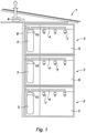
Figure 2 est un plan d'un logement de l'habitation détaillant l'emplacement des différents éléments de l'installation ; -
Figure 3 est une vue schématique d'une partie de l'installation, selon une première forme de réalisation de l'invention ; -
Figure 4 est une vue correspondant à lafigure 3 , d'une seconde forme de réalisation de l'invention.
-
Figure 1 is a schematic representation of a collective dwelling equipped with an installation according to the invention: -
Figure 2 is a plan of a dwelling housing detailing the location of the various elements of the facility; -
Figure 3 is a schematic view of part of the installation, according to a first embodiment of the invention; -
Figure 4 is a view corresponding to thefigure 3 of a second embodiment of the invention.
Une habitation collective 1 équipée d'une installation de production d'eau chaude sanitaire est représentée à la
L'habitation comporte une pluralité de logements 2 répartis sur plusieurs étages. Seul un logement 2 par étage est représenté à la
Chaque logement 2 comporte un chauffe-eau comportant un réservoir 3 à l'intérieur duquel est stocké un fluide à chauffer.Each
Chaque logement 2 est en outre équipé d'au moins une conduite d'extraction d'air 4, en particulier au niveau des pièces techniques 5, comme cela est mieux représenté à la
Dans le cas représenté aux
Les débits d'air insufflé et d'air extrait indiqué à la
La conduite 4 d'extraction d'air de chaque logement 2 est raccordée à un réseau d'extraction d'air 8 commun aux différents logements, le réseau d'extraction d'air 8 comportant une partie supérieure équipée d'un ventilateur 9.The
En outre, chaque logement 2 comporte des moyens d'échange de chaleur 10 agencés pour chauffer le fluide contenu dans le réservoir 3 à partir de l'air extrait circulant dans la conduite 4.In addition, each
Selon une autre possibilité de l'invention, un réseau d'insufflation d'air 11 commun aux différents logements (
La structure des moyens d'échange de chaleur 10 va maintenant être décrite plus en détail en référence aux
Selon une première forme de réalisation représentée à la
Le circuit thermodynamique 13 comporte successivement, dans le sens de circulation de fluide frigorigène, un évaporateur 14 disposé dans la conduite 4 et agencé pour échanger de la chaleur avec l'air extrait, un compresseur 15, un condenseur 16 agencé pour échanger de la chaleur avec le fluide contenu dans le réservoir 3, et un détendeur 17. Le sens de circulation du fluide frigorigène est représenté par des flèches. En outre, la phase et la pression du fluide frigorigène sont identifiés par les références VBP (Vapeur Basse Pression), VHP (Vapeur Haute Pression), LHP (Liquide Haute Pression) et LBP (Liquide Basse Pression).The
Plus particulièrement, le condenseur 16 présente la forme d'un sepentin et est disposé à l'intérieur du réservoir 3 du chauffe-eau, de manière à échanger directement de la chaleur avec le fluide contenu dans le réservoir 3.More particularly, the
L'installation comporte en outre un échangeur de chaleur de type double flux 18, dans lequel le flux d'air insufflé F1 dans le logement 2 échange de la chaleur avec le flux d'air extrait F2 du logement 2.The installation further comprises a heat exchanger of the
Plus précisément, l'échangeur double flux 18 permet d'échanger de la chaleur entre le flux d'air entrant F1 provenant du réseau d'insufflation d'air 11 et dirigé vers le logement 2 par l'intermédiaire d'une conduite de distribution individuelle 19 permettant de distribuer l'air insufflé dans les différentes pièces de séjour 12, et le flux d'air sortant F2 provenant des pièces techniques 5, acheminé depuis ces différentes pièces par la conduite d'extraction d'air 4, et dirigé vers le réseau d'extraction d'air 8.More specifically, the double
Ainsi, l'échangeur de chaleur de type double flux 18 est disposé en amont de l'évaporateur 14 du circuit thermodynamique 13, dans le sens de circulation de l'air extrait.Thus, the heat exchanger of the
En outre, l'installation comporte des moyens de recyclage 20 permettant de diriger une partie de l'air insufflé, provenant du réseau d'insufflation 11, directement dans le réseau d'extraction d'air 8, c'est-à-dire sans le rejeter dans le logement 2. Les moyens de recyclage sont situés en amont de l'évaporateur, dans le sens de circulation de l'air extrait, et comportent un clapet commandé ainsi qu'une branche de dérivation permettant de dériver l'air insufflé hors de l'échangeur double flux 18.In addition, the installation comprises recycling means 20 for directing a portion of the air blown from the
Dans une seconde forme de réalisation représentée à la
La structure des moyens d'échange de chaleur 10 est décrite ci-dessus en combinaison avec une ventilation de type double-flux. Toutefois, la structure des moyens d'échange de chaleur 10 reste inchangée dans le cas d'une ventilation simple flux, seuls le réseau d'insufflation d'air 11 et l'échangeur de chaleur de type double flux 18 étant dans ce cas inexistants.The structure of the heat exchange means 10 is described above in combination with a double flow type ventilation. However, the structure of the heat exchange means 10 remains unchanged in the case of single flow ventilation, only the
Il apparaît ainsi que l'installation selon l'invention permet de récupérer, au moins en partie, l'énergie thermique disponible dans l'air extrait de manière à la transférer au fluide contenue dans le réservoir afin de produire de l'eau chaude sanitaire avec un rendement élevé.It thus appears that the installation according to the invention makes it possible to recover, at least in part, the heat energy available in the extracted air so as to transfer it to the fluid contained in the tank in order to produce hot water with high efficiency.
En outre, une telle installation peut être adaptée à des habitations collectives, du fait de l'utilisation d'un réseau d'extraction d'air commun aux différents logements auquel chaque conduite d'extraction d'air correspondante est raccordée.In addition, such an installation can be adapted to collective dwellings, because of the use of an air extraction network common to the different housing to which each corresponding air exhaust duct is connected.
De plus, dans le cas particulier de la ventilation double flux, l'utilisation d'un échangeur de type double flux permet de limiter les déperditions thermiques au travers de l'air extrait.In addition, in the particular case of double-flow ventilation, the use of a double-flow type heat exchanger makes it possible to limit thermal losses through the extracted air.
Claims (8)
- An installation for producing domestic hot water for a congregate housing (1) including a plurality of water heaters, intended to equip a plurality of individual dwellings (2) of the housing (1), each water heater including a tank (3) inside which a fluid to be heated is stored, each dwelling (2) being further equipped with at least one air extraction conduit (4), in particular at the level of the technical rooms (5), connected to an air extraction network (8) common to the different dwellings (2), each dwelling further including heat exchange means (10) arranged to exchange heat between the extracted air circulating in the air extraction conduit (4) and the fluid contained in the tank (3), so as to heat the fluid in order to produce domestic hot water, characterized in that the air extraction network (8) common to the different dwellings (2) is equipped with at least one fan (9) adapted to create a depression in said extraction network, so as to perform the extraction of air from each dwelling.
- The installation according to claim 1, characterized in that the heat exchange means (10) include a thermodynamic circuit (13) inside which a refrigerant fluid circulates, the thermodynamic circuit including an evaporator (14) arranged to exchange heat with the extracted air, a compressor (15), a pressure reducer valve (17), and a condenser (16) arranged to exchange heat with the fluid contained in the tank (3).
- The installation according to any of claims 1 and 2, characterized in that the condenser (16) is disposed inside the tank (3) of the water heater, so as to directly exchange heat with the fluid contained in the tank (3).
- The installation according to any of claims 1 and 2, characterized in that the heat exchange means (10) include a heat exchange secondary circuit (21) inside which a heat-transfer fluid circulates, passing through the condenser (16) so as to exchange heat with the heat-transfer fluid, the secondary circuit (21) further including a heat exchanger (23) disposed inside the tank (3) of the water heater, so as to exchange heat with the fluid contained in the tank (3).
- The installation according to any of claims 1 to 4, characterized in that it includes an air blowing network (11) common to the different dwellings (2), each dwelling being equipped with a double-flow type heat exchanger (18), in which the air flow (F1) blown into the dwelling (2) and coming from the air blowing network (11) exchanges heat with the air flow (F2) extracted from the dwelling (2).
- The installation according to claim 5, characterized in that the double-flow type heat exchanger (18) is disposed upstream of the means (10) for exchanging heat between the extracted air and the fluid contained in the tank (3), in the direction of circulation of the extracted air.
- The installation according to any of claims 5 and 6, characterized in that it includes recycling means (20) allowing directing a portion of the blown air coming from the blowing network (11), directly in the air extraction network (8), upstream of the heat exchange means (10) in the direction of circulation of the extracted air.
- The installation according to any of claims 1 to 7, characterized in that the air blowing network (11) common to the different dwelling (2) is equipped with at least one fan adapted to perform the air blowing of each dwelling.
Priority Applications (1)
| Application Number | Priority Date | Filing Date | Title |
|---|---|---|---|
| PL09703886T PL2232155T3 (en) | 2008-01-22 | 2009-01-19 | Facility for producing sanitary hot water for congregate housing |
Applications Claiming Priority (2)
| Application Number | Priority Date | Filing Date | Title |
|---|---|---|---|
| FR0800315A FR2926626B1 (en) | 2008-01-22 | 2008-01-22 | HOT WATER PRODUCTION FACILITY FOR COLLECTIVE HOUSING |
| PCT/FR2009/050065 WO2009092976A2 (en) | 2008-01-22 | 2009-01-19 | Facility for producing sanitary hot water for congregate housing |
Publications (2)
| Publication Number | Publication Date |
|---|---|
| EP2232155A2 EP2232155A2 (en) | 2010-09-29 |
| EP2232155B1 true EP2232155B1 (en) | 2019-12-04 |
Family
ID=39673416
Family Applications (1)
| Application Number | Title | Priority Date | Filing Date |
|---|---|---|---|
| EP09703886.3A Active EP2232155B1 (en) | 2008-01-22 | 2009-01-19 | Facility for producing sanitary hot water for congregate housing |
Country Status (7)
| Country | Link |
|---|---|
| US (1) | US20110023517A1 (en) |
| EP (1) | EP2232155B1 (en) |
| CA (1) | CA2712189A1 (en) |
| ES (1) | ES2774179T3 (en) |
| FR (1) | FR2926626B1 (en) |
| PL (1) | PL2232155T3 (en) |
| WO (1) | WO2009092976A2 (en) |
Families Citing this family (15)
| Publication number | Priority date | Publication date | Assignee | Title |
|---|---|---|---|---|
| US8805597B2 (en) * | 2009-02-10 | 2014-08-12 | Steffes Corporation | Electrical appliance energy consumption control |
| FR2962794B1 (en) * | 2010-07-15 | 2014-11-21 | Anjos Ventilation | METHOD FOR CONTROLLING AN AIR TREATMENT PLANT AND INSTALLATION USING SUCH A METHOD |
| FR2966563B1 (en) * | 2010-10-25 | 2012-12-21 | Atlantic Climatisation Et Ventilation | HOT WATER PRODUCTION FACILITY FOR COLLECTIVE HOUSING |
| FR2966564A1 (en) | 2010-10-25 | 2012-04-27 | Atlantic Climatisation Et Ventilation | HOT WATER PRODUCTION FACILITY FOR COLLECTIVE HOUSING COMPRISING A COMMON AIR EXTRACTION FAN |
| FR2966565B1 (en) | 2010-10-25 | 2012-12-07 | Atlantic Climatisation Et Ventilation | DOMESTIC HOT WATER PRODUCTION INSTALLATION FOR COLLECTIVE HOUSING AND PROCESS FOR IMPLEMENTING SUCH AN INSTALLATION |
| FR2972246B1 (en) * | 2011-03-04 | 2013-03-15 | Aldes Aeraulique | HOT WATER PRODUCTION FACILITY OPERATING A THERMODYNAMIC TECHNOLOGY IN A COLLECTIVE HOUSING AND ADAPTED METHOD FOR VENTILATION MANAGEMENT |
| FR2982345B1 (en) * | 2011-11-04 | 2018-01-19 | Atlantic Climatisation Et Ventilation | HOT WATER PRODUCTION FACILITIES |
| FR2984998B1 (en) * | 2011-12-27 | 2014-01-24 | France Air | AIR TREATMENT BOX |
| FR2998353B1 (en) * | 2012-11-20 | 2014-12-19 | Aldes Aeraulique | METHOD AND APPARATUS FOR REFRIGERATING AIR IN A HOME AND METHOD OF OPERATION |
| EP2778542A1 (en) * | 2013-03-12 | 2014-09-17 | BDR Thermea Group | Facility for producing domestic hot water in a dwelling via a thermodynamic water heater on extracted air |
| BE1021689B1 (en) * | 2013-09-25 | 2016-01-08 | Renson Ventilation Nv | CLIMATIZING DEVICE AND METHOD FOR CONTROLLING SUCH CLIMATIZING DEVICE |
| CA2935852C (en) | 2014-01-31 | 2023-03-14 | Steffes Corporation | Power consumption management through energy storage devices |
| FR3017192B1 (en) * | 2014-02-06 | 2019-01-25 | France Air | HOT WATER PRODUCTION FACILITY AND METHOD FOR CONTROLLING SUCH FACILITY |
| JP6949130B2 (en) * | 2017-09-26 | 2021-10-13 | 三菱電機株式会社 | Refrigeration cycle equipment |
| US11209199B2 (en) * | 2019-02-07 | 2021-12-28 | Heatcraft Refrigeration Products Llc | Cooling system |
Family Cites Families (19)
| Publication number | Priority date | Publication date | Assignee | Title |
|---|---|---|---|---|
| FR2356098A1 (en) * | 1975-11-19 | 1978-01-20 | Costa Mario | Domestic heat recovery system - uses ventilation air to heat water using compressor for air |
| FR2602310B1 (en) | 1986-07-31 | 1988-11-10 | Roussel Michel | DEVICE FOR TRANSMITTING A COLLECTIVE SAFETY SIGNAL FOR A MECHANICAL EXTRACTION NETWORK OF AIR AND COMBUSTION GAS FROM A SET OF LIVING ROOMS |
| FI83134C (en) * | 1987-12-18 | 1991-05-27 | Ilmaterae Oy | FOERFARANDE OCH ANORDNING FOER REGLERING AV LUFTSTROEMMAR OCH TRYCK I LUFTKONDITIONERING. |
| SE8901045L (en) * | 1989-03-23 | 1990-09-24 | Givent Roger Ericsson Ab | PROCEDURE AND DEVICE FOR TEMPERATURE CONTROL IN A BUILDING |
| US5056712A (en) * | 1989-12-06 | 1991-10-15 | Enck Harry J | Water heater controller |
| US5050394A (en) * | 1990-09-20 | 1991-09-24 | Electric Power Research Institute, Inc. | Controllable variable speed heat pump for combined water heating and space cooling |
| DE4412844C2 (en) * | 1994-02-09 | 1999-06-17 | Stiebel Eltron Gmbh & Co Kg | Air conditioner |
| DE29706131U1 (en) * | 1997-04-07 | 1997-05-22 | Hoose Heinz Dieter | Heat pumps / air conditioning system with heat recovery |
| FR2763390B1 (en) * | 1997-05-13 | 1999-07-23 | Andre Amphoux | VENTILATION SYSTEM WITH ADDITIONAL AIR INJECTION FOR DRAFT ASSISTANCE |
| DE29710913U1 (en) * | 1997-06-23 | 1997-09-25 | Hoose Heinz Dieter | Heat pump system with supply air heating |
| FR2769693B1 (en) | 1997-10-14 | 1999-12-17 | Aldes Aeraulique | DUAL FLOW VENTILATION SYSTEM |
| DE19819639C2 (en) * | 1998-05-05 | 2000-05-31 | Caldyn Apparatebau Gmbh | Heating passive houses |
| DE10058273A1 (en) * | 2000-11-23 | 2002-05-29 | Woelfle Gmbh | Ventilator comprises heat pump unit, service and drinking water accumulator, heating water accumulator, electric heater, heat exchanger, closeable connections. |
| DE20300465U1 (en) * | 2003-01-10 | 2003-07-24 | Erlus Baustoffwerke | Aerating and ventilating system for buildings has fresh air shaft and exhaust air shaft in vertical air shaft and located vertically and parallel to one another |
| JP3918786B2 (en) * | 2003-07-30 | 2007-05-23 | 株式会社デンソー | Hot water storage type heat pump water heater |
| WO2005075896A1 (en) | 2004-02-06 | 2005-08-18 | J.E. Stork Ventilatoren B.V. | Method and apparatus for cooling ventilation air to be supplied to a space |
| FR2870326B1 (en) | 2004-05-14 | 2006-07-28 | France Air | INSTALLATION FOR HEATING, REFRIGERATION AND VENTILATION OF COLLECTIVE HOUSING |
| DE202004008792U1 (en) * | 2004-06-02 | 2004-08-26 | K.C.R. 28 Küchen und mehr GmbH | A building ventilation system has fan assisted extraction of air from rooms and entry to a vertical chimney only in the roof space or cellar |
| DE102006019175B4 (en) * | 2006-04-21 | 2008-05-08 | Stiebel Eltron Gmbh & Co. Kg | heat pump device |
-
2008
- 2008-01-22 FR FR0800315A patent/FR2926626B1/en not_active Expired - Fee Related
-
2009
- 2009-01-19 ES ES09703886T patent/ES2774179T3/en active Active
- 2009-01-19 US US12/864,085 patent/US20110023517A1/en not_active Abandoned
- 2009-01-19 WO PCT/FR2009/050065 patent/WO2009092976A2/en active Application Filing
- 2009-01-19 PL PL09703886T patent/PL2232155T3/en unknown
- 2009-01-19 EP EP09703886.3A patent/EP2232155B1/en active Active
- 2009-01-19 CA CA2712189A patent/CA2712189A1/en not_active Abandoned
Non-Patent Citations (1)
| Title |
|---|
| None * |
Also Published As
| Publication number | Publication date |
|---|---|
| US20110023517A1 (en) | 2011-02-03 |
| FR2926626A1 (en) | 2009-07-24 |
| WO2009092976A2 (en) | 2009-07-30 |
| FR2926626B1 (en) | 2010-06-25 |
| ES2774179T3 (en) | 2020-07-17 |
| EP2232155A2 (en) | 2010-09-29 |
| PL2232155T3 (en) | 2020-05-18 |
| CA2712189A1 (en) | 2009-07-30 |
| WO2009092976A3 (en) | 2009-09-17 |
Similar Documents
| Publication | Publication Date | Title |
|---|---|---|
| EP2232155B1 (en) | Facility for producing sanitary hot water for congregate housing | |
| EP3371516B1 (en) | A district thermal energy distribution system | |
| EP2312227B1 (en) | Controlled mechanical ventilation device of the type with reversible double thermodynamic flow with domestic hot water production | |
| WO2014044864A1 (en) | Domestic water heating facility having a heating function | |
| FR2947896A1 (en) | INSTALLATION FOR HEATING AND / OR SUPPLYING HOT WATER | |
| EP2306107A1 (en) | Double-flow ventilation system and method for domestic hot water production and compact heating with built-in heat pump | |
| FR2938900A1 (en) | Air conditioning device for use in e.g. house, has circuit whose secondary heat exchanger is controlled and arranged in downstream of section and exchanging heat between air and exchanging medium formed by solar sensor | |
| FR2922632A1 (en) | Dual flow, thermodynamic, reversible controlled mechanical ventilation installation for dwelling, has heat exchanger connected to secondary circuit, where fluid utilized for heating receiver is circulated at interior of secondary circuit | |
| EP2232156B1 (en) | Plant for producing sanitary hot water | |
| FR2982345A1 (en) | Installation for production of warm water for single-family housing, has control units e.g. flap, for selectively directing exhaust air passing through heat exchange units to pipe and/or for directing air outwardly of housing | |
| FR3057651B1 (en) | HOT WATER PRODUCTION FACILITY FOR A COLLECTIVE CONSTRUCTION | |
| EP2241827B1 (en) | Cogeneration installation and process using a fuel cell for heating and for producing sanitary hot water | |
| FR3072767A1 (en) | THERMODYNAMIC MACHINE HAVING A DEFROSTING EXCHANGER | |
| FR3064725B1 (en) | INSTALLATION FOR THE THERMAL REQUIREMENTS OF A SANITARY WATER BUILDING AND HEATING COMPRISING A THERMODYNAMIC HEATING | |
| BE1026742B1 (en) | Method for transferring condensation energy from the steam of cogeneration fumes | |
| EP3139100B1 (en) | System and method for producing hot water | |
| FR2984997A1 (en) | Installation for treatment of air in building e.g. office, has thermodynamic water-heater, where calorific energy is extracted from air, and water-heater is connected to storage balloon for providing pre-heated water to building | |
| FR3063132B1 (en) | THERMAL MANAGEMENT SYSTEM FOR AIR AND HOT WATER PRODUCTION FOR A LOCAL | |
| US20140251309A1 (en) | Method and configuration for heating buildings with an infrared heater | |
| EP2461108B1 (en) | Wall-mounted boiler device, device for heating a fluid, facility for heating a room and method for adapting a wall-mounted boiler device | |
| FR2947895A3 (en) | Heating system for supplying heating circuit with radiators or ensuring provision of household warm water from boiler, has boiler, which is connected and combined with heating circuit | |
| EP3969819B1 (en) | Hydraulic interconnection system for thermal network | |
| FR2979975A1 (en) | Reversible thermodynamic double flow-type controlled mechanical ventilation installation for ventilating, heating, cooling and producing hot water of building of e.g. industry, has heat exchangers placed in instilled and extracted air ducts | |
| EP2743601B1 (en) | Compact inner module for thermal control facility with heat pump | |
| FR2913755A1 (en) | Ventilation device for heat regulation system of e.g. dwelling, has turbine mounted in cylindrical case and comprising rotation shaft integrated to ventilation unit, where turbine is rotated by circulation of heat transfer fluid in case |
Legal Events
| Date | Code | Title | Description |
|---|---|---|---|
| PUAI | Public reference made under article 153(3) epc to a published international application that has entered the european phase |
Free format text: ORIGINAL CODE: 0009012 |
|
| 17P | Request for examination filed |
Effective date: 20100628 |
|
| AK | Designated contracting states |
Kind code of ref document: A2 Designated state(s): AT BE BG CH CY CZ DE DK EE ES FI FR GB GR HR HU IE IS IT LI LT LU LV MC MK MT NL NO PL PT RO SE SI SK TR |
|
| AX | Request for extension of the european patent |
Extension state: AL BA RS |
|
| RIN1 | Information on inventor provided before grant (corrected) |
Inventor name: BUSEYNE, SERGE Inventor name: LABAUME, DAMIEN |
|
| TPAC | Observations filed by third parties |
Free format text: ORIGINAL CODE: EPIDOSNTIPA |
|
| DAX | Request for extension of the european patent (deleted) | ||
| STAA | Information on the status of an ep patent application or granted ep patent |
Free format text: STATUS: EXAMINATION IS IN PROGRESS |
|
| 17Q | First examination report despatched |
Effective date: 20170404 |
|
| GRAP | Despatch of communication of intention to grant a patent |
Free format text: ORIGINAL CODE: EPIDOSNIGR1 |
|
| STAA | Information on the status of an ep patent application or granted ep patent |
Free format text: STATUS: GRANT OF PATENT IS INTENDED |
|
| INTG | Intention to grant announced |
Effective date: 20190821 |
|
| GRAS | Grant fee paid |
Free format text: ORIGINAL CODE: EPIDOSNIGR3 |
|
| GRAA | (expected) grant |
Free format text: ORIGINAL CODE: 0009210 |
|
| STAA | Information on the status of an ep patent application or granted ep patent |
Free format text: STATUS: THE PATENT HAS BEEN GRANTED |
|
| AK | Designated contracting states |
Kind code of ref document: B1 Designated state(s): AT BE BG CH CY CZ DE DK EE ES FI FR GB GR HR HU IE IS IT LI LT LU LV MC MK MT NL NO PL PT RO SE SI SK TR |
|
| REG | Reference to a national code |
Ref country code: GB Ref legal event code: FG4D Free format text: NOT ENGLISH |
|
| REG | Reference to a national code |
Ref country code: CH Ref legal event code: EP |
|
| REG | Reference to a national code |
Ref country code: AT Ref legal event code: REF Ref document number: 1209886 Country of ref document: AT Kind code of ref document: T Effective date: 20191215 |
|
| REG | Reference to a national code |
Ref country code: DE Ref legal event code: R096 Ref document number: 602009060609 Country of ref document: DE |
|
| REG | Reference to a national code |
Ref country code: IE Ref legal event code: FG4D Free format text: LANGUAGE OF EP DOCUMENT: FRENCH |
|
| REG | Reference to a national code |
Ref country code: NL Ref legal event code: MP Effective date: 20191204 |
|
| REG | Reference to a national code |
Ref country code: LT Ref legal event code: MG4D |
|
| PG25 | Lapsed in a contracting state [announced via postgrant information from national office to epo] |
Ref country code: LV Free format text: LAPSE BECAUSE OF FAILURE TO SUBMIT A TRANSLATION OF THE DESCRIPTION OR TO PAY THE FEE WITHIN THE PRESCRIBED TIME-LIMIT Effective date: 20191204 Ref country code: SE Free format text: LAPSE BECAUSE OF FAILURE TO SUBMIT A TRANSLATION OF THE DESCRIPTION OR TO PAY THE FEE WITHIN THE PRESCRIBED TIME-LIMIT Effective date: 20191204 Ref country code: NO Free format text: LAPSE BECAUSE OF FAILURE TO SUBMIT A TRANSLATION OF THE DESCRIPTION OR TO PAY THE FEE WITHIN THE PRESCRIBED TIME-LIMIT Effective date: 20200304 Ref country code: FI Free format text: LAPSE BECAUSE OF FAILURE TO SUBMIT A TRANSLATION OF THE DESCRIPTION OR TO PAY THE FEE WITHIN THE PRESCRIBED TIME-LIMIT Effective date: 20191204 Ref country code: BG Free format text: LAPSE BECAUSE OF FAILURE TO SUBMIT A TRANSLATION OF THE DESCRIPTION OR TO PAY THE FEE WITHIN THE PRESCRIBED TIME-LIMIT Effective date: 20200304 Ref country code: LT Free format text: LAPSE BECAUSE OF FAILURE TO SUBMIT A TRANSLATION OF THE DESCRIPTION OR TO PAY THE FEE WITHIN THE PRESCRIBED TIME-LIMIT Effective date: 20191204 Ref country code: GR Free format text: LAPSE BECAUSE OF FAILURE TO SUBMIT A TRANSLATION OF THE DESCRIPTION OR TO PAY THE FEE WITHIN THE PRESCRIBED TIME-LIMIT Effective date: 20200305 |
|
| PG25 | Lapsed in a contracting state [announced via postgrant information from national office to epo] |
Ref country code: HR Free format text: LAPSE BECAUSE OF FAILURE TO SUBMIT A TRANSLATION OF THE DESCRIPTION OR TO PAY THE FEE WITHIN THE PRESCRIBED TIME-LIMIT Effective date: 20191204 |
|
| REG | Reference to a national code |
Ref country code: ES Ref legal event code: FG2A Ref document number: 2774179 Country of ref document: ES Kind code of ref document: T3 Effective date: 20200717 |
|
| PG25 | Lapsed in a contracting state [announced via postgrant information from national office to epo] |
Ref country code: EE Free format text: LAPSE BECAUSE OF FAILURE TO SUBMIT A TRANSLATION OF THE DESCRIPTION OR TO PAY THE FEE WITHIN THE PRESCRIBED TIME-LIMIT Effective date: 20191204 Ref country code: CZ Free format text: LAPSE BECAUSE OF FAILURE TO SUBMIT A TRANSLATION OF THE DESCRIPTION OR TO PAY THE FEE WITHIN THE PRESCRIBED TIME-LIMIT Effective date: 20191204 Ref country code: NL Free format text: LAPSE BECAUSE OF FAILURE TO SUBMIT A TRANSLATION OF THE DESCRIPTION OR TO PAY THE FEE WITHIN THE PRESCRIBED TIME-LIMIT Effective date: 20191204 Ref country code: RO Free format text: LAPSE BECAUSE OF FAILURE TO SUBMIT A TRANSLATION OF THE DESCRIPTION OR TO PAY THE FEE WITHIN THE PRESCRIBED TIME-LIMIT Effective date: 20191204 Ref country code: PT Free format text: LAPSE BECAUSE OF FAILURE TO SUBMIT A TRANSLATION OF THE DESCRIPTION OR TO PAY THE FEE WITHIN THE PRESCRIBED TIME-LIMIT Effective date: 20200429 |
|
| PG25 | Lapsed in a contracting state [announced via postgrant information from national office to epo] |
Ref country code: SK Free format text: LAPSE BECAUSE OF FAILURE TO SUBMIT A TRANSLATION OF THE DESCRIPTION OR TO PAY THE FEE WITHIN THE PRESCRIBED TIME-LIMIT Effective date: 20191204 Ref country code: IS Free format text: LAPSE BECAUSE OF FAILURE TO SUBMIT A TRANSLATION OF THE DESCRIPTION OR TO PAY THE FEE WITHIN THE PRESCRIBED TIME-LIMIT Effective date: 20200404 |
|
| REG | Reference to a national code |
Ref country code: CH Ref legal event code: PL |
|
| REG | Reference to a national code |
Ref country code: DE Ref legal event code: R097 Ref document number: 602009060609 Country of ref document: DE |
|
| REG | Reference to a national code |
Ref country code: AT Ref legal event code: MK05 Ref document number: 1209886 Country of ref document: AT Kind code of ref document: T Effective date: 20191204 |
|
| PG25 | Lapsed in a contracting state [announced via postgrant information from national office to epo] |
Ref country code: MC Free format text: LAPSE BECAUSE OF FAILURE TO SUBMIT A TRANSLATION OF THE DESCRIPTION OR TO PAY THE FEE WITHIN THE PRESCRIBED TIME-LIMIT Effective date: 20191204 |
|
| PLBE | No opposition filed within time limit |
Free format text: ORIGINAL CODE: 0009261 |
|
| STAA | Information on the status of an ep patent application or granted ep patent |
Free format text: STATUS: NO OPPOSITION FILED WITHIN TIME LIMIT |
|
| REG | Reference to a national code |
Ref country code: BE Ref legal event code: MM Effective date: 20200131 |
|
| PG25 | Lapsed in a contracting state [announced via postgrant information from national office to epo] |
Ref country code: LU Free format text: LAPSE BECAUSE OF NON-PAYMENT OF DUE FEES Effective date: 20200119 Ref country code: DK Free format text: LAPSE BECAUSE OF FAILURE TO SUBMIT A TRANSLATION OF THE DESCRIPTION OR TO PAY THE FEE WITHIN THE PRESCRIBED TIME-LIMIT Effective date: 20191204 |
|
| 26N | No opposition filed |
Effective date: 20200907 |
|
| PG25 | Lapsed in a contracting state [announced via postgrant information from national office to epo] |
Ref country code: SI Free format text: LAPSE BECAUSE OF FAILURE TO SUBMIT A TRANSLATION OF THE DESCRIPTION OR TO PAY THE FEE WITHIN THE PRESCRIBED TIME-LIMIT Effective date: 20191204 Ref country code: BE Free format text: LAPSE BECAUSE OF NON-PAYMENT OF DUE FEES Effective date: 20200131 Ref country code: CH Free format text: LAPSE BECAUSE OF NON-PAYMENT OF DUE FEES Effective date: 20200131 Ref country code: AT Free format text: LAPSE BECAUSE OF FAILURE TO SUBMIT A TRANSLATION OF THE DESCRIPTION OR TO PAY THE FEE WITHIN THE PRESCRIBED TIME-LIMIT Effective date: 20191204 Ref country code: LI Free format text: LAPSE BECAUSE OF NON-PAYMENT OF DUE FEES Effective date: 20200131 |
|
| PG25 | Lapsed in a contracting state [announced via postgrant information from national office to epo] |
Ref country code: IT Free format text: LAPSE BECAUSE OF FAILURE TO SUBMIT A TRANSLATION OF THE DESCRIPTION OR TO PAY THE FEE WITHIN THE PRESCRIBED TIME-LIMIT Effective date: 20191204 Ref country code: IE Free format text: LAPSE BECAUSE OF NON-PAYMENT OF DUE FEES Effective date: 20200119 |
|
| GBPC | Gb: european patent ceased through non-payment of renewal fee |
Effective date: 20200304 |
|
| PG25 | Lapsed in a contracting state [announced via postgrant information from national office to epo] |
Ref country code: GB Free format text: LAPSE BECAUSE OF NON-PAYMENT OF DUE FEES Effective date: 20200304 |
|
| PG25 | Lapsed in a contracting state [announced via postgrant information from national office to epo] |
Ref country code: TR Free format text: LAPSE BECAUSE OF FAILURE TO SUBMIT A TRANSLATION OF THE DESCRIPTION OR TO PAY THE FEE WITHIN THE PRESCRIBED TIME-LIMIT Effective date: 20191204 Ref country code: MT Free format text: LAPSE BECAUSE OF FAILURE TO SUBMIT A TRANSLATION OF THE DESCRIPTION OR TO PAY THE FEE WITHIN THE PRESCRIBED TIME-LIMIT Effective date: 20191204 Ref country code: CY Free format text: LAPSE BECAUSE OF FAILURE TO SUBMIT A TRANSLATION OF THE DESCRIPTION OR TO PAY THE FEE WITHIN THE PRESCRIBED TIME-LIMIT Effective date: 20191204 |
|
| PG25 | Lapsed in a contracting state [announced via postgrant information from national office to epo] |
Ref country code: MK Free format text: LAPSE BECAUSE OF FAILURE TO SUBMIT A TRANSLATION OF THE DESCRIPTION OR TO PAY THE FEE WITHIN THE PRESCRIBED TIME-LIMIT Effective date: 20191204 |
|
| PGFP | Annual fee paid to national office [announced via postgrant information from national office to epo] |
Ref country code: ES Payment date: 20230206 Year of fee payment: 15 |
|
| PGFP | Annual fee paid to national office [announced via postgrant information from national office to epo] |
Ref country code: PL Payment date: 20230104 Year of fee payment: 15 Ref country code: DE Payment date: 20221230 Year of fee payment: 15 |
|
| P01 | Opt-out of the competence of the unified patent court (upc) registered |
Effective date: 20230526 |
|
| PGFP | Annual fee paid to national office [announced via postgrant information from national office to epo] |
Ref country code: FR Payment date: 20231229 Year of fee payment: 16 |
|
| PGFP | Annual fee paid to national office [announced via postgrant information from national office to epo] |
Ref country code: ES Payment date: 20240207 Year of fee payment: 16 |