EP2232091B1 - Cage for roller bodies - Google Patents
Cage for roller bodies Download PDFInfo
- Publication number
- EP2232091B1 EP2232091B1 EP08869295.9A EP08869295A EP2232091B1 EP 2232091 B1 EP2232091 B1 EP 2232091B1 EP 08869295 A EP08869295 A EP 08869295A EP 2232091 B1 EP2232091 B1 EP 2232091B1
- Authority
- EP
- European Patent Office
- Prior art keywords
- cage
- webs
- rolling
- rolling elements
- web
- Prior art date
- Legal status (The legal status is an assumption and is not a legal conclusion. Google has not performed a legal analysis and makes no representation as to the accuracy of the status listed.)
- Not-in-force
Links
Images

Classifications
-
- F—MECHANICAL ENGINEERING; LIGHTING; HEATING; WEAPONS; BLASTING
- F16—ENGINEERING ELEMENTS AND UNITS; GENERAL MEASURES FOR PRODUCING AND MAINTAINING EFFECTIVE FUNCTIONING OF MACHINES OR INSTALLATIONS; THERMAL INSULATION IN GENERAL
- F16C—SHAFTS; FLEXIBLE SHAFTS; ELEMENTS OR CRANKSHAFT MECHANISMS; ROTARY BODIES OTHER THAN GEARING ELEMENTS; BEARINGS
- F16C19/00—Bearings with rolling contact, for exclusively rotary movement
- F16C19/02—Bearings with rolling contact, for exclusively rotary movement with bearing balls essentially of the same size in one or more circular rows
- F16C19/10—Bearings with rolling contact, for exclusively rotary movement with bearing balls essentially of the same size in one or more circular rows for axial load mainly
-
- F—MECHANICAL ENGINEERING; LIGHTING; HEATING; WEAPONS; BLASTING
- F16—ENGINEERING ELEMENTS AND UNITS; GENERAL MEASURES FOR PRODUCING AND MAINTAINING EFFECTIVE FUNCTIONING OF MACHINES OR INSTALLATIONS; THERMAL INSULATION IN GENERAL
- F16C—SHAFTS; FLEXIBLE SHAFTS; ELEMENTS OR CRANKSHAFT MECHANISMS; ROTARY BODIES OTHER THAN GEARING ELEMENTS; BEARINGS
- F16C33/00—Parts of bearings; Special methods for making bearings or parts thereof
- F16C33/30—Parts of ball or roller bearings
- F16C33/38—Ball cages
- F16C33/3887—Details of individual pockets, e.g. shape or ball retaining means
-
- F—MECHANICAL ENGINEERING; LIGHTING; HEATING; WEAPONS; BLASTING
- F16—ENGINEERING ELEMENTS AND UNITS; GENERAL MEASURES FOR PRODUCING AND MAINTAINING EFFECTIVE FUNCTIONING OF MACHINES OR INSTALLATIONS; THERMAL INSULATION IN GENERAL
- F16C—SHAFTS; FLEXIBLE SHAFTS; ELEMENTS OR CRANKSHAFT MECHANISMS; ROTARY BODIES OTHER THAN GEARING ELEMENTS; BEARINGS
- F16C33/00—Parts of bearings; Special methods for making bearings or parts thereof
- F16C33/30—Parts of ball or roller bearings
- F16C33/38—Ball cages
- F16C33/42—Ball cages made from wire or sheet metal strips
- F16C33/422—Ball cages made from wire or sheet metal strips made from sheet metal
- F16C33/425—Ball cages made from wire or sheet metal strips made from sheet metal from a single part, e.g. ribbon cages with one corrugated annular part
Definitions
- the invention relates to a cage for spherical rolling elements, for example, for thrust bearings or flat guides, which is formed in a longitudinal section in an approximately W-shaped, with an axially aligned radially outer side wall and an axially aligned radially inner side wall, which are interconnected by webs and so gaps form for receiving the rolling elements, wherein the webs are formed such that they limit the freedom of movement of the rolling elements in the radial direction, in the axial direction and in the tangential direction of the cage, wherein the webs have starting from the side walls obliquely extending web portions.
- Cages for rolling elements are known to guide the rolling elements between the mutually rotating rolling element raceways safely and keep at a distance. This is the only way to ensure a uniform load distribution, to prevent mutual obstruction of the rolling elements and thus to ensure faultless functioning of the rolling bearing.
- the skilled person strives to be able to accommodate as many rolling elements in the rolling bearing in a compact manner in order to provide by a high rolling element density bearings for highest loads can.
- this requires the creation of a corresponding number of pockets or spaces in the rolling element cage and in turn leads to a constructive weakening of the cage. The result is a lack of stiffness and increased risk of mechanical failure of the cage in operation.
- W-shaped or sigma-shaped cages have proven themselves in cross-section in this connection. These are generally formed in one piece and have a comparatively high rigidity with high achievable rolling element density.
- the cage is designed for cylindrical rolling elements and has webs with a specially designed profile, such that the parallel to the horizontal plane of division of the rolling elements extending web portions have a greater width than the transverse thereto extending web portions, and the leadership of the rolling elements therefore exclusively by the takes place parallel to the dividing plane of the rolling elements extending web sections.
- the profile of the webs is adapted to limit the freedom of movement of the rolling elements in two degrees of freedom (the rolling elements in these degrees of freedom even close to fix), namely both in the circumferential direction and in the axial direction of the cage.
- the invention has the object of developing a generic cage for a rolling bearing such that the leadership of the rolling elements is improved over known solutions.
- the invention is based on the finding that by suitable choice of the web profile of the cage whose leadership properties can be significantly improved.
- the invention relates to a circular cage for spherical rolling elements, for example for thrust bearings or flat guides, which is formed in a longitudinal section in an approximately W-shaped, with an axially aligned radially outer side wall and an axially aligned radially inner side wall, which by webs interconnected and thus form spaces for receiving the rolling elements, wherein the webs are formed such that they limit the freedom of movement of the rolling elements in the radial direction, in the axial direction and in the tangential direction of the cage, wherein the webs starting from the side walls obliquely extending web portions exhibit.
- this rolling bearing cage is also provided for solving the problem that the restriction of the freedom of movement of the rolling elements in the radial direction by guide surfaces, which are formed on the inclined web portions.
- the guide surfaces enclose an angle ⁇ with one another which is in each case less than 180 degrees.
- the inclined web portions are connected to each other via a radially extending web portion, wherein such a web portion of a web with the radially extending web portion of an adjacent web each forms a clearance, which is smaller than the diameter of the recorded between the webs rolling element.
- the spaces have longitudinally to the side walls extending sides whose distance is smaller than the diameter of the rolling bodies received in the interstices, whereby the holder of the rolling elements is ensured in the axial direction of the cage in a structurally simple manner.
- a highly expedient embodiment of the inventive concept provides that the intermediate spaces formed between the webs in the plan view have an approximately square contour, wherein the sides merge into one another by means of radii. On the one hand, this makes it possible to significantly reduce the notch effect in these areas, and on the other hand this contributes to increasing the packing or rolling element density. However, the packing density can also be increased by reducing the web width.
- the webs have an axial extent H which is greater than an axial extent h associated with the side walls, then the stability of the cage can be positively influenced.
- the stability of the cage can be positively influenced.
- a roller bearing assembly should be equipped with at least one cage according to the invention to improve the reliability of the rolling bearing assembly.
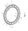
- FIGS. 1 to 3 a first preferred embodiment of a cage 1 according to the invention is shown in different views.
- the cage 1 has a radially outer side wall 2 and a radially inner side wall 3, which are connected to one another via webs 4.
- the webs 4 are arranged distributed at equal intervals over the circumference of the cage 1 and form between adjacent webs 4 spaces 5, in which rolling elements 6 can be mounted, which good the FIGS. 4 to 9 is removable.
- the webs 4, starting from the side walls 2, 3 initially obliquely to axially outwardly extending web portions 40 which merge into an approximately radially extending web portion 41 having an axial extent H ( Fig. 2 ).
- the obliquely extending web portions 40 have guide surfaces 400 for the rolling elements 6 at their sides facing the mounted rolling elements 6 and enclose an angle ⁇ ⁇ 180 degrees with one another.
- FIG. 3 shows the intermediate spaces 5 in the plan view in the outline approximately in the shape of a square with strongly rounded corners and with two parallel, along the side walls 2, 3 extending sides 51, 52, said sides 51, 52 with the webs 4 via Radii r are connected.
- the cage 1 is preferably made in one piece from drawn and stamped sheet steel.
- the thickness s of the steel sheet (cf. Fig. 2 ) can be adjusted according to the ball diameter of the rolling elements 6 and function of the unit accordingly be.
- the rolling elements 6 should protrude only slightly or not at all against the axially flat side of the cage 1.
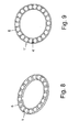
- the cage 1 according to the invention with mounted rolling elements 6 is shown.
- the rolling elements 6 are spherical and have a diameter d. But they could also have other shapes, such as cylindrical. This would require a corresponding structural adaptation of the cage 1.
- the sides 51 and 52 extending along the side walls 3, 2 have a distance a from each other which is smaller than the diameter d of the rolling bodies 6.
- the radially extending web portion 41 of a web 4 with the radially extending web portion 41 of an adjacent web 4 each forms a clearance A, which is smaller than the diameter d of the recorded between the webs 4 rolling element 6.
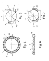
- the freedom of movement of the rolling elements 6 in three To limit degrees of freedom, namely in a first, radially to the cage 1 standing degree of freedom F1, in a second, axially to the cage 1 standing degree of freedom F2 and a third, tangent to the cage 1 degree of freedom F3 (see FIGS. 4, 5 and 7 ).
- FIG. 9 a second embodiment of a cage according to the invention 1 'shown in which, in contrast to the cage 1 of the Fig. 8 the cage 1 'narrower webs 4' has. This makes it possible to increase the packing density of the cage 1 with rolling elements 6 and thereby a greater bearing capacity of a rolling bearing constructed in this way.
Description
Die Erfindung betrifft einen Käfig für kugelförmige Wälzkörper, beispielsweise für Axiallager oder Flachführungen, welcher im Längsschnitt in etwa W-förmig ausgebildet ist, mit einer axial ausgerichteten radial äußeren Seitenwand und einer axial ausgerichteten radial inneren Seitenwand, die durch Stege miteinander verbunden sind und so Zwischenräume zur Aufnahme der Wälzkörper bilden, wobei die Stege derartig ausgebildet sind, dass sie die Bewegungsfreiheit der Wälzkörper in radialer Richtung, in axialer Richtung und in tangentialer Richtung des Käfigs begrenzen, wobei die Stege ausgehend von den Seitenwänden schräg verlaufende Stegabschnitte aufweisen.The invention relates to a cage for spherical rolling elements, for example, for thrust bearings or flat guides, which is formed in a longitudinal section in an approximately W-shaped, with an axially aligned radially outer side wall and an axially aligned radially inner side wall, which are interconnected by webs and so gaps form for receiving the rolling elements, wherein the webs are formed such that they limit the freedom of movement of the rolling elements in the radial direction, in the axial direction and in the tangential direction of the cage, wherein the webs have starting from the side walls obliquely extending web portions.
Käfige für Wälzkörper dienen bekanntlich dazu, die Wälzkörper zwischen den sich gegeneinander drehenden Wälzkörper-Laufbahnen sicher zu führen und auf Abstand zu halten. Nur so wird eine gleichmäßige Lastverteilung ermöglicht, eine gegenseitige Behinderung der Wälzkörper verhindert und damit eine einwandfreie Funktion des Wälzlagers gewährleistet. Zudem ist der Fachmann bestrebt, möglichst viele Wälzkörper im Wälzlager in kompakter Weise unterbringen zu können, um durch eine hohe Wälzkörperdichte Wälzlager für höchste Beanspruchungen bereitstellen zu können. Dies erfordert jedoch die Schaffung von entsprechend vielen Taschen bzw. Freiräumen in dem Wälzkörper-Käfig und führt wiederum zu einer konstruktiven Schwächung des Käfigs. Die Folge ist eine mangelnde Steifigkeit und eine erhöhte Gefahr des mechanischen Versagens des Käfigs im Betrieb.Cages for rolling elements are known to guide the rolling elements between the mutually rotating rolling element raceways safely and keep at a distance. This is the only way to ensure a uniform load distribution, to prevent mutual obstruction of the rolling elements and thus to ensure faultless functioning of the rolling bearing. In addition, the skilled person strives to be able to accommodate as many rolling elements in the rolling bearing in a compact manner in order to provide by a high rolling element density bearings for highest loads can. However, this requires the creation of a corresponding number of pockets or spaces in the rolling element cage and in turn leads to a constructive weakening of the cage. The The result is a lack of stiffness and increased risk of mechanical failure of the cage in operation.
Im Bereich der Axial-Nadellager haben sich in diesem Zusammenhang im Querschnitt W-förmige bzw. Sigma-förmige Käfige bewährt. Diese sind in der Regel einstückig ausgebildet und weisen eine vergleichsweise große Steifigkeit bei hoher erzielbarer Wälzkörperdichte auf.In the area of the axial needle roller bearings, W-shaped or sigma-shaped cages have proven themselves in cross-section in this connection. These are generally formed in one piece and have a comparatively high rigidity with high achievable rolling element density.
Aus der
Bei einem mechanischen Versagen des Käfigs (Bruch einer der Seitenwände), welches in der Regel durch äußere Einwirkungen ausgelöst wird, kann es passieren, dass es zu einem "Überrollen" durch die Wälzkörper im Bereich des beschädigten Käfigs kommt, das heißt, die Wälzkörper verlassen in radialer Richtung ihren Laufbahn- bzw. Funktionsdurchmesser. Dies führt zu einer örtlichen Schwächung der Lager-Tragfähigkeit und kann unter Umständen weiteren Schaden nach sich ziehen.In the event of a mechanical failure of the cage (fracture of one of the side walls), which is usually triggered by external influences, it can happen that the rolling elements roll over in the area of the damaged cage, that is, leave the rolling elements in the radial direction of their career or functional diameter. This leads to a local weakening of the bearing capacity and may possibly cause further damage.
In der
Der Erfindung liegt die Aufgabe zugrunde, einen gattungsgemäßen Käfig für ein Wälzlager derart weiterzubilden, dass die Führung der Wälzkörper gegenüber bekannten Lösungen verbessert wird.The invention has the object of developing a generic cage for a rolling bearing such that the leadership of the rolling elements is improved over known solutions.
Der Erfindung liegt die Erkenntnis zugrunde, dass durch geeignete Wahl des Stegprofils des Käfigs dessen Führungseigenschaften entscheidend verbessert werden können.The invention is based on the finding that by suitable choice of the web profile of the cage whose leadership properties can be significantly improved.
Gemäß den Merkmalen des Hauptanspruchs betrifft die Erfindung einen kreisförmigen Käfig für kugelförmige Wälzkörper, beispielsweise für Axiallager oder Flachführungen, welcher im Längsschnitt in etwa W-förmig ausgebildet ist, mit einer axial ausgerichteten radial äußeren Seitenwand und einer axial ausgerichteten radial inneren Seitenwand, die durch Stege miteinander verbunden sind und so Zwischenräume zur Aufnahme der Wälzkörper bilden, wobei die Stege derartig ausgebildet sind, dass sie die Bewegungsfreiheit der Wälzkörper in radialer Richtung, in axialer Richtung und in tangentialer Richtung des Käfigs begrenzen, wobei die Stege ausgehend von den Seitenwänden schräg verlaufende Stegabschnitte aufweisen. Bei diesem Wälzlagerkäfig ist zur Lösung der Aufgabe außerdem vorgesehen, dass die Einschränkung der Bewegungsfreiheit der Wälzkörper in radialer Richtung durch Führungsflächen erfolgt, die an den schräg verlaufenden Stegabschnitten ausgebildet sind.According to the features of the main claim, the invention relates to a circular cage for spherical rolling elements, for example for thrust bearings or flat guides, which is formed in a longitudinal section in an approximately W-shaped, with an axially aligned radially outer side wall and an axially aligned radially inner side wall, which by webs interconnected and thus form spaces for receiving the rolling elements, wherein the webs are formed such that they limit the freedom of movement of the rolling elements in the radial direction, in the axial direction and in the tangential direction of the cage, wherein the webs starting from the side walls obliquely extending web portions exhibit. In this rolling bearing cage is also provided for solving the problem that the restriction of the freedom of movement of the rolling elements in the radial direction by guide surfaces, which are formed on the inclined web portions.
Durch diesen Aufbau wird erreicht, dass die Führung der Wälzkörper deutlich verbessert ist. Außerdem ist die Gefahr eines Überrollens von Käfigteilen durch die Wälzkörper im Schadensfall deutlich reduziert. Die Wälzkörper werden somit allein durch die Stege immer an ihrem Funktionsdurchmesser bzw. an den Wälzkörperlaufbahnen der Lagerteile gehalten.By this construction it is achieved that the guidance of the rolling elements is significantly improved. In addition, the risk of rolling over of cage parts by the rolling elements in the event of damage is significantly reduced. The rolling elements are thus held solely by the webs always on their functional diameter or on the Wälzkörperlaufbahnen the bearing parts.
Die Unteransprüche beschreiben bevorzugte Weiterbildungen oder Ausgestaltungen der Erfindung.The subclaims describe preferred developments or refinements of the invention.
Gemäß einer ersten bevorzugten Weiterbildung ist vorgesehen, dass an jeder einem Wälzkörper zugeordneten Seite eines Stegs die Führungsflächen einen Winkel α miteinander einschließen, der jeweils kleiner als 180 Grad ist. Hierdurch wird unter Beibehaltung des W- bzw. Sigma-Profils mit einfachen Mitteln die radiale Führung der Wälzkörper ermöglicht.According to a first preferred embodiment, it is provided that on each side of a web associated with a rolling element, the guide surfaces enclose an angle α with one another which is in each case less than 180 degrees. As a result, the radial guidance of the rolling elements is made possible while retaining the W or sigma profile with simple means.
Es ist sehr vorteilhaft, wenn die schräg verlaufenden Stegabschnitte über einen radial verlaufenden Stegabschnitt miteinander verbunden sind, wobei ein solcher Stegabschnitt eines Steges mit dem radial verlaufenden Stegabschnitt eines benachbarten Steges jeweils einen lichten Abstand bildet, welcher kleiner ist als der Durchmesser des zwischen den Stegen aufgenommenen Wälzkörpers. Durch diese Maßnahme ist eine leichte, einklipsartige Montage der Wälzkörper in die zwischen den Stegen befindlichen Zwischenräume möglich, denn bei der Montage drückt der Wälzkörper die benachbarten Stege elastisch auf und bei Erreichen der Wälzkörper-Funktionsstellung federn die Stege wieder in ihre Ausgangsstellung zurück.It is very advantageous if the inclined web portions are connected to each other via a radially extending web portion, wherein such a web portion of a web with the radially extending web portion of an adjacent web each forms a clearance, which is smaller than the diameter of the recorded between the webs rolling element. By this measure, a light, einklipsartige mounting of the rolling elements in the interstices located between the webs is possible, because during assembly of the rolling elements presses the adjacent webs elastically and upon reaching the rolling element functional position, the webs spring back into their starting position.
Es kann dabei vorteilhafterweise vorgesehen sein, dass die Zwischenräume längs zu den Seitenwänden verlaufende Seiten aufweisen, deren Abstand kleiner ist als der Durchmesser der in den Zwischenräumen aufgenommenen Wälzkörper, wodurch die Halterung der Wälzkörper auch in axialer Richtung des Käfigs auf konstruktiv einfache Weise gewährleistet ist.It can be advantageously provided that the spaces have longitudinally to the side walls extending sides whose distance is smaller than the diameter of the rolling bodies received in the interstices, whereby the holder of the rolling elements is ensured in the axial direction of the cage in a structurally simple manner.
Eine höchst zweckmäßige Ausgestaltung des Erfindungsgedankens sieht vor, dass die zwischen den Stegen gebildeten Zwischenräume in der Draufsicht eine in etwa quadratische Kontur aufweisen, wobei deren Seiten mittels Radien ineinander übergehen. Dies ermöglicht zum einen eine deutliche Verminderung der Kerbwirkung in diesen Bereichen, zum anderen trägt dies zur Erhöhung der Packungs- bzw. Wälzkörperdichte bei. Die Packungsdichte lässt sich allerdings auch durch Verminderung der Stegbreite erhöhen.A highly expedient embodiment of the inventive concept provides that the intermediate spaces formed between the webs in the plan view have an approximately square contour, wherein the sides merge into one another by means of radii. On the one hand, this makes it possible to significantly reduce the notch effect in these areas, and on the other hand this contributes to increasing the packing or rolling element density. However, the packing density can also be increased by reducing the web width.
Wenn vorteilhafterweise die Stege eine axiale Erstreckung H aufweisen, die größer als eine den Seitenwänden zugeordnete axiale Erstreckung h ist, dann kann die Stabilität des Käfigs positiv beeinflusst werden. Außerdem lässt sich durch die axiale Erstreckung der Stege die axiale Freigängigkeit der Wälzkörper beeinflussen.If, advantageously, the webs have an axial extent H which is greater than an axial extent h associated with the side walls, then the stability of the cage can be positively influenced. In addition, can be influenced by the axial extent of the webs, the axial clearance of the rolling elements.
Zweckmäßigerweise sollte eine Wälzlager-Baueinheit mit wenigstens einem erfindungsgemäßen Käfig ausgestattet sein, um die Funktionssicherheit der Wälzlager-Baueinheit zu verbessern.Conveniently, a roller bearing assembly should be equipped with at least one cage according to the invention to improve the reliability of the rolling bearing assembly.
Die Erfindung wird im Folgenden anhand der beiliegenden Zeichnung anhand bevorzugter Ausführungsbeispiele näher erläutert. Darin zeigt
- Fig. 1
- ein erstes Ausführungsbeispiel eines erfindungsgemäßen Käfigs in einer perspektivischen Ansicht,
- Fig. 2
- eine Schnittansicht gemäß Schnittverlauf II-II aus
Fig. 1 , - Fig. 3
- eine Detailansicht III-III aus
Fig. 1 in der Draufsicht, - Fig. 4
- eine Draufsicht auf einen erfindungsgemäßen Käfig mit montierten Wälzkörpern,
- Fig. 5
- eine Schnittansicht gemäß dem Schnittverlauf V-V aus
Fig. 4 , - Fig. 6
- eine Schnittansicht gemäß dem Schnittverlauf VI-VI aus
Fig. 4 , - Fig. 7
- eine Detailansicht VII aus
Fig. 6 , - Fig. 8
- der Käfig gemäß
Fig. 1 in perspektivischer Ansicht mit montierten Wälzkörpern, und - Fig. 9
- ein zweites Ausführungsbeispiel eines erfindungsgemäßen Käfigs in perspektivischer Ansicht mit montierten Wälzkörpern.
- Fig. 1
- A first embodiment of a cage according to the invention in a perspective view,
- Fig. 2
- a sectional view according to section line II-II off
Fig. 1 . - Fig. 3
- a detailed view of III-III
Fig. 1 in the plan view, - Fig. 4
- a top view of a cage according to the invention with mounted rolling elements,
- Fig. 5
- a sectional view according to the section VV from
Fig. 4 . - Fig. 6
- a sectional view according to the section line VI-VI from
Fig. 4 . - Fig. 7
- a detailed view VII from
Fig. 6 . - Fig. 8
- the cage according to
Fig. 1 in perspective view with mounted rolling elements, and - Fig. 9
- A second embodiment of a cage according to the invention in a perspective view with mounted rolling elements.
Zunächst wird auf die
Wie insbesondere
Der Käfig 1 ist vorzugsweise einstückig aus gezogenem und gestanztem Stahlblech hergestellt. Die Dicke s des Stahlblechs (vgl.
In den
Schließlich ist in
- 1, 1'1, 1 '
- KäfigCage
- 22
- Radial äußere Seitenwand des KäfigsRadially outer side wall of the cage
- 33
- Radial innere Seitenwand des KäfigsRadial inner side wall of the cage
- 4, 4'4, 4 '
- Stegweb
- 4040
- Schräg verlaufender StegabschnittSloping bridge section
- 400400
- Führungsfläche des schräg verlaufenden StegabschnittsGuide surface of the inclined web portion
- 4141
- Radial verlaufender StegabschnittRadially extending bridge section
- 55
- Zwischenraum zwischen zwei benachbarten StegenSpace between two adjacent webs
- 5151
- Längs der Seitenwände verlaufende Seite eines ZwischenraumsSide of a gap extending along the side walls
- 5252
- Längs der Seitenwände verlaufende Seite eines ZwischenraumsSide of a gap extending along the side walls
- 66
- Wälzkörperrolling elements
- aa
- Abstand zwischen den längs der Seitenwände verlaufenden Seiten des ZwischenraumesDistance between the sides of the gap running along the side walls
- AA
- Abstand der benachbarten horizontalen StegabschnitteDistance between the adjacent horizontal web sections
- dd
- Durchmesser der WälzkörperDiameter of the rolling elements
- F1F1
- Freiheitsgrad in radialer Richtung des Käfigs, in dem die Bewegungsfreiheit der Wälzkörper eingeschränkt istDegree of freedom in the radial direction of the cage, in which the freedom of movement of the rolling elements is limited
- F2F2
- Freiheitsgrad in axialer Richtung des Käfigs, in dem die Bewegungsfreiheit der Wälzkörper eingeschränkt istDegree of freedom in the axial direction of the cage, in which the freedom of movement of the rolling elements is limited
- F3F3
- Freiheitsgrad in tangentialer Richtung des Käfigs, in dem die Bewegungsfreiheit der Wälzkörper eingeschränkt istDegree of freedom in the tangential direction of the cage, in which the freedom of movement of the rolling elements is limited
- hH
- Axiale Erstreckung der SeitenwändeAxial extension of the side walls
- HH
- Axiale Erstreckung der StegeAxial extent of the webs
- rr
- Radien über die die längs der Seitenwände verlaufenden Seiten mit den Stegen verbunden sindRadii over which the sides along the sides extending sides are connected to the webs
- ss
- Dicke des KäfigwerkstoffesThickness of the cage material
- αα
- Winkel, den die Führungsflächen miteinander einschließenAngle that the guide surfaces enclose with each other
Claims (7)
- Cage (1, 1') for spherical rolling bodies (6), for example for axial bearings or flat guides, which is of approximately W-shaped form in longitudinal section, with an axially oriented radially outer side wall (2) and with an axially oriented radially inner side wall (3) which are connected to one another by means of webs (4) and thus form interspaces (5) for receiving the rolling bodies (6), the webs (4) being formed in such a way that they limit the freedom of movement of the rolling bodies (6) in the radial direction (F1), in the axial direction (F2) and in the tangential direction (F3) of the cage (1, 1'), the webs (4) having web portions (40) running obliquely from the side walls (2, 3), characterized in that the restriction of the freedom of movement of the rolling bodies (6) in the radial direction (F1) takes place by means of guide faces (400) which are formed on the obliquely running web portions (40).
- Cage according to Claim 1, characterized in that, on each side, assigned to a rolling body (6), of a web (4), the guide faces (400) form with one another an angle (α) which in each case is smaller than 180 degrees.
- Cage according to Claim 1 or 2, characterized in that the obliquely running web portions (40) are connected to one another via a radially running web portion (41), such a web portion (41) of a web (4) forming with the radially running web portion (41) of an adjacent web (4) in each case a clearance (A) which is smaller than the diameter (d) of the rolling body (6) received between the webs (4).
- Cage according to one of the preceding claims, characterized in that the interspaces (5) have an approximately square contour in a top view, their sides emerging one into the other by means of radii (r).
- Cage according to Claim 4, characterized in that the interspaces (5) have sides (51, 52) which run longitudinally with respect to the side walls (2, 3) and the clearance (a) between which is smaller than the diameter (d) of the rolling bodies (6) received in the interspaces (5).
- Cage according to one of the preceding claims, characterized in that the webs (4) have an axial extent (H) which is greater than the axial extent (h) of the side walls (2, 3).
- Rolling-bearing structural unit with at least one cage (1, 1') according to at least one of the preceding claims.
Priority Applications (1)
| Application Number | Priority Date | Filing Date | Title |
|---|---|---|---|
| SI200831187T SI2232091T1 (en) | 2008-01-11 | 2008-11-10 | Cage for roller bodies |
Applications Claiming Priority (2)
| Application Number | Priority Date | Filing Date | Title |
|---|---|---|---|
| DE102008004033A DE102008004033B4 (en) | 2008-01-11 | 2008-01-11 | Cage for rolling elements |
| PCT/EP2008/065204 WO2009086964A2 (en) | 2008-01-11 | 2008-11-10 | Cage for roller bodies |
Publications (2)
| Publication Number | Publication Date |
|---|---|
| EP2232091A2 EP2232091A2 (en) | 2010-09-29 |
| EP2232091B1 true EP2232091B1 (en) | 2014-01-22 |
Family
ID=40686256
Family Applications (1)
| Application Number | Title | Priority Date | Filing Date |
|---|---|---|---|
| EP08869295.9A Not-in-force EP2232091B1 (en) | 2008-01-11 | 2008-11-10 | Cage for roller bodies |
Country Status (8)
| Country | Link |
|---|---|
| US (1) | US8690452B2 (en) |
| EP (1) | EP2232091B1 (en) |
| JP (1) | JP2011509383A (en) |
| CN (1) | CN101918726B (en) |
| BR (1) | BRPI0822025A2 (en) |
| DE (1) | DE102008004033B4 (en) |
| SI (1) | SI2232091T1 (en) |
| WO (1) | WO2009086964A2 (en) |
Families Citing this family (6)
| Publication number | Priority date | Publication date | Assignee | Title |
|---|---|---|---|---|
| DE102009048875A1 (en) * | 2009-10-09 | 2011-04-14 | Schaeffler Technologies Gmbh & Co. Kg | Rolling cage for a ball bearing |
| DE102013221363A1 (en) * | 2013-10-22 | 2015-04-23 | Schaeffler Technologies Gmbh & Co. Kg | Axial cage for cylindrical rolling elements |
| DE102013225996A1 (en) | 2013-12-16 | 2015-06-18 | Schaeffler Technologies AG & Co. KG | Plastic roller bearing cage for a thrust bearing and thrust bearing |
| DE102015223255A1 (en) | 2015-11-25 | 2017-06-01 | Schaeffler Technologies AG & Co. KG | A ball bearing retainer |
| DE102016205440A1 (en) * | 2016-04-01 | 2017-10-05 | Schaeffler Technologies AG & Co. KG | Cage for an axial ball bearing, thrust ball bearing with cage and method for manufacturing the cage |
| DE102021105455A1 (en) | 2021-03-08 | 2022-09-08 | Schaeffler Technologies AG & Co. KG | Cage for a thrust ball bearing and method of assembling a ball race with this cage |
Family Cites Families (22)
| Publication number | Priority date | Publication date | Assignee | Title |
|---|---|---|---|---|
| DE280119C (en) * | 1900-01-01 | |||
| DE212758C (en) * | 1900-01-01 | |||
| DE279476C (en) * | ||||
| FR340433A (en) * | 1904-02-15 | 1904-07-06 | Ernst Gustav Hoffmann | Ball bearing improvements |
| FR459683A (en) * | 1913-06-12 | 1913-11-11 | Cie Anonyme Francaise Pour La Fabrication Des Roulements A Billes Dwf | Ball cage |
| US1232523A (en) * | 1917-05-15 | 1917-07-10 | Edward S Folk | Roller-bearing. |
| US1395244A (en) * | 1920-07-31 | 1921-10-25 | Gustaf E Andre | Bearing |
| DE1840219U (en) * | 1961-08-23 | 1961-10-26 | Schaeffler Ohg Industriewerk | SINGLE-PIECE CAGE FOR CYLINDRICAL ROLLED BODY. |
| DE1174113B (en) * | 1962-02-20 | 1964-07-16 | Schaeffler Ohg Industriewerk | Axial cage for cylindrical rolling elements |
| US3306685A (en) * | 1965-07-19 | 1967-02-28 | Mcgill Mfg Company Inc | Angular contact ball bearing assembly |
| JP3316307B2 (en) * | 1994-06-07 | 2002-08-19 | 日本トムソン株式会社 | Thrust bearing |
| DE19740435A1 (en) * | 1997-09-15 | 1999-03-18 | Schaeffler Waelzlager Ohg | Method for manufacturing rolling element bearing cages from thin-walled strip |
| DE19812252A1 (en) * | 1998-03-20 | 1999-09-23 | Schaeffler Waelzlager Ohg | Needle roller bearing cage with slit in shoulder between two crosspieces |
| JP3933336B2 (en) * | 1999-01-28 | 2007-06-20 | Ntn株式会社 | Cage for thrust needle roller bearing and method for manufacturing the same |
| JP4165226B2 (en) * | 2003-01-06 | 2008-10-15 | 株式会社ジェイテクト | Thrust roller bearing cage |
| JP2004353775A (en) * | 2003-05-29 | 2004-12-16 | Ntn Corp | Ball thrust bearing |
| US7178982B2 (en) * | 2003-11-13 | 2007-02-20 | Hiwin Mikrosystem Corp. | Retaining device for rolling-element |
| JP4606128B2 (en) * | 2004-11-11 | 2011-01-05 | 宇都宮機器株式会社 | Method for manufacturing roller bearing cage |
| JP4432741B2 (en) * | 2004-11-16 | 2010-03-17 | 株式会社ジェイテクト | Thrust roller bearing cage |
| FR2883941B1 (en) * | 2005-04-04 | 2008-09-12 | Skf Ab | CAGE DEVICE FOR BEARING, BEARING AND HARMONIC REDUCER |
| JP4591386B2 (en) * | 2006-03-02 | 2010-12-01 | 株式会社ジェイテクト | Thrust roller bearing |
| CN101876341B (en) * | 2010-05-24 | 2012-01-25 | 杭州钱江压缩机有限公司 | Plane bearing of compressor crankshaft |
-
2008
- 2008-01-11 DE DE102008004033A patent/DE102008004033B4/en active Active
- 2008-11-10 BR BRPI0822025A patent/BRPI0822025A2/en active Search and Examination
- 2008-11-10 CN CN2008801245386A patent/CN101918726B/en active Active
- 2008-11-10 WO PCT/EP2008/065204 patent/WO2009086964A2/en active Application Filing
- 2008-11-10 US US12/812,352 patent/US8690452B2/en not_active Expired - Fee Related
- 2008-11-10 JP JP2010541723A patent/JP2011509383A/en active Pending
- 2008-11-10 SI SI200831187T patent/SI2232091T1/en unknown
- 2008-11-10 EP EP08869295.9A patent/EP2232091B1/en not_active Not-in-force
Also Published As
| Publication number | Publication date |
|---|---|
| US8690452B2 (en) | 2014-04-08 |
| JP2011509383A (en) | 2011-03-24 |
| CN101918726B (en) | 2013-03-27 |
| WO2009086964A3 (en) | 2010-08-12 |
| DE102008004033B4 (en) | 2012-05-31 |
| DE102008004033A1 (en) | 2009-07-16 |
| WO2009086964A2 (en) | 2009-07-16 |
| CN101918726A (en) | 2010-12-15 |
| US20100278473A1 (en) | 2010-11-04 |
| EP2232091A2 (en) | 2010-09-29 |
| SI2232091T1 (en) | 2014-06-30 |
| BRPI0822025A2 (en) | 2019-02-26 |
Similar Documents
| Publication | Publication Date | Title |
|---|---|---|
| DE2635053C2 (en) | Rolling bearings for longitudinal movements | |
| EP3359832B1 (en) | Cage segment of a rolling bearing | |
| EP2232091B1 (en) | Cage for roller bodies | |
| DE2422488C2 (en) | Rolling bearings with inserted raceways | |
| WO2007065414A1 (en) | Radial antifriction bearing, especially single-row grooved antifriction bearing | |
| WO2018086650A1 (en) | Roller bearing cage having retaining claws | |
| DE102015200381A1 (en) | Cage segment of a rolling bearing | |
| EP4212751A1 (en) | Bearing cage | |
| WO2011018491A1 (en) | Cage segment for a plastic cage of a rolling bearing and rolling bearing with a cage segment of this type | |
| WO2017186210A1 (en) | Cage segment of a cylindrical roller bearing | |
| DE102019112815A1 (en) | Rolling bearing cage | |
| DE2125402A1 (en) | Pocket cage for roller bearings | |
| DE3418621A1 (en) | Rolling bearing | |
| WO2009086965A2 (en) | Cage for roller bodies | |
| DE102019213988A1 (en) | Bearing cage, especially axial bearing cage | |
| DE102008062913A1 (en) | segment cage | |
| DE102017129773A1 (en) | Spherical roller bearings | |
| DE102007058824A1 (en) | Radial rolling bearing used in machine tools comprises a guiding board arranged on the track of the inner bearing ring and a guiding board arranged on the track of the outer bearing ring | |
| DE2257761A1 (en) | ROLLER BEARING CAGE | |
| DE202008017091U1 (en) | segment cage | |
| DE10030268A1 (en) | Cage for cylindrical roller bearing has endfaces of side rings with stud stumps able to expand axially | |
| WO2007088144A2 (en) | Double-row thin ring bearing comprising inclined rolls | |
| DE102013222008B4 (en) | Bearing cage for an angular contact roller bearing and axial angular contact roller bearing | |
| DE102008018380A1 (en) | Roller bearing cage for guiding roller body between two paths of roller bearing, has roller bearing slots whose respective pairs of two corners provided opposite along diagonals exhibit different corner geometries | |
| DE102016211917A1 (en) | Rolling bearing cage or rolling bearing cage segment |
Legal Events
| Date | Code | Title | Description |
|---|---|---|---|
| PUAI | Public reference made under article 153(3) epc to a published international application that has entered the european phase |
Free format text: ORIGINAL CODE: 0009012 |
|
| AK | Designated contracting states |
Kind code of ref document: A2 Designated state(s): AT BE BG CH CY CZ DE DK EE ES FI FR GB GR HR HU IE IS IT LI LT LU LV MC MT NL NO PL PT RO SE SI SK TR |
|
| AX | Request for extension of the european patent |
Extension state: AL BA MK RS |
|
| 17P | Request for examination filed |
Effective date: 20110214 |
|
| RBV | Designated contracting states (corrected) |
Designated state(s): AT BE BG CH CY CZ DE DK EE ES FI FR GB GR HR HU IE IS IT LI LT LU LV MC MT NL NO PL PT RO SE SI SK TR |
|
| DAX | Request for extension of the european patent (deleted) | ||
| RAP1 | Party data changed (applicant data changed or rights of an application transferred) |
Owner name: SCHAEFFLER TECHNOLOGIES AG & CO. KG |
|
| GRAP | Despatch of communication of intention to grant a patent |
Free format text: ORIGINAL CODE: EPIDOSNIGR1 |
|
| RIC1 | Information provided on ipc code assigned before grant |
Ipc: F16C 19/10 20060101ALI20130906BHEP Ipc: F16C 33/42 20060101AFI20130906BHEP Ipc: F16C 33/38 20060101ALI20130906BHEP |
|
| INTG | Intention to grant announced |
Effective date: 20131007 |
|
| GRAS | Grant fee paid |
Free format text: ORIGINAL CODE: EPIDOSNIGR3 |
|
| GRAA | (expected) grant |
Free format text: ORIGINAL CODE: 0009210 |
|
| AK | Designated contracting states |
Kind code of ref document: B1 Designated state(s): AT BE BG CH CY CZ DE DK EE ES FI FR GB GR HR HU IE IS IT LI LT LU LV MC MT NL NO PL PT RO SE SI SK TR |
|
| REG | Reference to a national code |
Ref country code: GB Ref legal event code: FG4D Free format text: NOT ENGLISH |
|
| REG | Reference to a national code |
Ref country code: CH Ref legal event code: EP |
|
| REG | Reference to a national code |
Ref country code: AT Ref legal event code: REF Ref document number: 650955 Country of ref document: AT Kind code of ref document: T Effective date: 20140215 |
|
| REG | Reference to a national code |
Ref country code: IE Ref legal event code: FG4D Free format text: LANGUAGE OF EP DOCUMENT: GERMAN |
|
| REG | Reference to a national code |
Ref country code: DE Ref legal event code: R096 Ref document number: 502008011280 Country of ref document: DE Effective date: 20140313 |
|
| RAP2 | Party data changed (patent owner data changed or rights of a patent transferred) |
Owner name: SCHAEFFLER TECHNOLOGIES GMBH & CO. KG |
|
| REG | Reference to a national code |
Ref country code: DE Ref legal event code: R081 Ref document number: 502008011280 Country of ref document: DE Owner name: SCHAEFFLER TECHNOLOGIES AG & CO. KG, DE Free format text: FORMER OWNER: SCHAEFFLER TECHNOLOGIES AG & CO. KG, 91074 HERZOGENAURACH, DE Effective date: 20140212 Ref country code: DE Ref legal event code: R081 Ref document number: 502008011280 Country of ref document: DE Owner name: SCHAEFFLER TECHNOLOGIES GMBH & CO. KG, DE Free format text: FORMER OWNER: SCHAEFFLER TECHNOLOGIES AG & CO. KG, 91074 HERZOGENAURACH, DE Effective date: 20140212 |
|
| REG | Reference to a national code |
Ref country code: NL Ref legal event code: VDEP Effective date: 20140122 |
|
| REG | Reference to a national code |
Ref country code: LT Ref legal event code: MG4D |
|
| PG25 | Lapsed in a contracting state [announced via postgrant information from national office to epo] |
Ref country code: IS Free format text: LAPSE BECAUSE OF FAILURE TO SUBMIT A TRANSLATION OF THE DESCRIPTION OR TO PAY THE FEE WITHIN THE PRESCRIBED TIME-LIMIT Effective date: 20140522 Ref country code: NO Free format text: LAPSE BECAUSE OF FAILURE TO SUBMIT A TRANSLATION OF THE DESCRIPTION OR TO PAY THE FEE WITHIN THE PRESCRIBED TIME-LIMIT Effective date: 20140422 Ref country code: LT Free format text: LAPSE BECAUSE OF FAILURE TO SUBMIT A TRANSLATION OF THE DESCRIPTION OR TO PAY THE FEE WITHIN THE PRESCRIBED TIME-LIMIT Effective date: 20140122 |
|
| PG25 | Lapsed in a contracting state [announced via postgrant information from national office to epo] |
Ref country code: FI Free format text: LAPSE BECAUSE OF FAILURE TO SUBMIT A TRANSLATION OF THE DESCRIPTION OR TO PAY THE FEE WITHIN THE PRESCRIBED TIME-LIMIT Effective date: 20140122 Ref country code: PT Free format text: LAPSE BECAUSE OF FAILURE TO SUBMIT A TRANSLATION OF THE DESCRIPTION OR TO PAY THE FEE WITHIN THE PRESCRIBED TIME-LIMIT Effective date: 20140522 Ref country code: SE Free format text: LAPSE BECAUSE OF FAILURE TO SUBMIT A TRANSLATION OF THE DESCRIPTION OR TO PAY THE FEE WITHIN THE PRESCRIBED TIME-LIMIT Effective date: 20140122 Ref country code: NL Free format text: LAPSE BECAUSE OF FAILURE TO SUBMIT A TRANSLATION OF THE DESCRIPTION OR TO PAY THE FEE WITHIN THE PRESCRIBED TIME-LIMIT Effective date: 20140122 Ref country code: CY Free format text: LAPSE BECAUSE OF FAILURE TO SUBMIT A TRANSLATION OF THE DESCRIPTION OR TO PAY THE FEE WITHIN THE PRESCRIBED TIME-LIMIT Effective date: 20140122 Ref country code: ES Free format text: LAPSE BECAUSE OF FAILURE TO SUBMIT A TRANSLATION OF THE DESCRIPTION OR TO PAY THE FEE WITHIN THE PRESCRIBED TIME-LIMIT Effective date: 20140122 |
|
| PG25 | Lapsed in a contracting state [announced via postgrant information from national office to epo] |
Ref country code: LV Free format text: LAPSE BECAUSE OF FAILURE TO SUBMIT A TRANSLATION OF THE DESCRIPTION OR TO PAY THE FEE WITHIN THE PRESCRIBED TIME-LIMIT Effective date: 20140122 Ref country code: HR Free format text: LAPSE BECAUSE OF FAILURE TO SUBMIT A TRANSLATION OF THE DESCRIPTION OR TO PAY THE FEE WITHIN THE PRESCRIBED TIME-LIMIT Effective date: 20140122 |
|
| REG | Reference to a national code |
Ref country code: DE Ref legal event code: R097 Ref document number: 502008011280 Country of ref document: DE |
|
| PG25 | Lapsed in a contracting state [announced via postgrant information from national office to epo] |
Ref country code: RO Free format text: LAPSE BECAUSE OF FAILURE TO SUBMIT A TRANSLATION OF THE DESCRIPTION OR TO PAY THE FEE WITHIN THE PRESCRIBED TIME-LIMIT Effective date: 20140122 Ref country code: CZ Free format text: LAPSE BECAUSE OF FAILURE TO SUBMIT A TRANSLATION OF THE DESCRIPTION OR TO PAY THE FEE WITHIN THE PRESCRIBED TIME-LIMIT Effective date: 20140122 Ref country code: EE Free format text: LAPSE BECAUSE OF FAILURE TO SUBMIT A TRANSLATION OF THE DESCRIPTION OR TO PAY THE FEE WITHIN THE PRESCRIBED TIME-LIMIT Effective date: 20140122 Ref country code: DK Free format text: LAPSE BECAUSE OF FAILURE TO SUBMIT A TRANSLATION OF THE DESCRIPTION OR TO PAY THE FEE WITHIN THE PRESCRIBED TIME-LIMIT Effective date: 20140122 |
|
| REG | Reference to a national code |
Ref country code: SK Ref legal event code: T3 Ref document number: E 16899 Country of ref document: SK |
|
| PG25 | Lapsed in a contracting state [announced via postgrant information from national office to epo] |
Ref country code: PL Free format text: LAPSE BECAUSE OF FAILURE TO SUBMIT A TRANSLATION OF THE DESCRIPTION OR TO PAY THE FEE WITHIN THE PRESCRIBED TIME-LIMIT Effective date: 20140122 |
|
| PLBE | No opposition filed within time limit |
Free format text: ORIGINAL CODE: 0009261 |
|
| STAA | Information on the status of an ep patent application or granted ep patent |
Free format text: STATUS: NO OPPOSITION FILED WITHIN TIME LIMIT |
|
| 26N | No opposition filed |
Effective date: 20141023 |
|
| REG | Reference to a national code |
Ref country code: DE Ref legal event code: R097 Ref document number: 502008011280 Country of ref document: DE Effective date: 20141023 |
|
| REG | Reference to a national code |
Ref country code: DE Ref legal event code: R081 Ref document number: 502008011280 Country of ref document: DE Owner name: SCHAEFFLER TECHNOLOGIES AG & CO. KG, DE Free format text: FORMER OWNER: SCHAEFFLER TECHNOLOGIES GMBH & CO. KG, 91074 HERZOGENAURACH, DE Effective date: 20150123 |
|
| REG | Reference to a national code |
Ref country code: CH Ref legal event code: PFA Owner name: SCHAEFFLER TECHNOLOGIES AG AND CO. KG, DE Free format text: FORMER OWNER: SCHAEFFLER TECHNOLOGIES GMBH AND CO. KG, DE |
|
| REG | Reference to a national code |
Ref country code: DE Ref legal event code: R119 Ref document number: 502008011280 Country of ref document: DE |
|
| PG25 | Lapsed in a contracting state [announced via postgrant information from national office to epo] |
Ref country code: BE Free format text: LAPSE BECAUSE OF NON-PAYMENT OF DUE FEES Effective date: 20141130 Ref country code: MC Free format text: LAPSE BECAUSE OF FAILURE TO SUBMIT A TRANSLATION OF THE DESCRIPTION OR TO PAY THE FEE WITHIN THE PRESCRIBED TIME-LIMIT Effective date: 20140122 |
|
| REG | Reference to a national code |
Ref country code: AT Ref legal event code: PC Ref document number: 650955 Country of ref document: AT Kind code of ref document: T Owner name: SCHAEFFLER TECHNOLOGIES AG & CO. KG, DE Effective date: 20150526 |
|
| REG | Reference to a national code |
Ref country code: IE Ref legal event code: MM4A |
|
| REG | Reference to a national code |
Ref country code: FR Ref legal event code: ST Effective date: 20150731 |
|
| PG25 | Lapsed in a contracting state [announced via postgrant information from national office to epo] |
Ref country code: DE Free format text: LAPSE BECAUSE OF NON-PAYMENT OF DUE FEES Effective date: 20150602 Ref country code: IE Free format text: LAPSE BECAUSE OF NON-PAYMENT OF DUE FEES Effective date: 20141110 |
|
| PG25 | Lapsed in a contracting state [announced via postgrant information from national office to epo] |
Ref country code: FR Free format text: LAPSE BECAUSE OF NON-PAYMENT OF DUE FEES Effective date: 20141201 |
|
| PG25 | Lapsed in a contracting state [announced via postgrant information from national office to epo] |
Ref country code: BG Free format text: LAPSE BECAUSE OF FAILURE TO SUBMIT A TRANSLATION OF THE DESCRIPTION OR TO PAY THE FEE WITHIN THE PRESCRIBED TIME-LIMIT Effective date: 20140122 |
|
| PG25 | Lapsed in a contracting state [announced via postgrant information from national office to epo] |
Ref country code: GR Free format text: LAPSE BECAUSE OF FAILURE TO SUBMIT A TRANSLATION OF THE DESCRIPTION OR TO PAY THE FEE WITHIN THE PRESCRIBED TIME-LIMIT Effective date: 20140423 |
|
| PG25 | Lapsed in a contracting state [announced via postgrant information from national office to epo] |
Ref country code: TR Free format text: LAPSE BECAUSE OF FAILURE TO SUBMIT A TRANSLATION OF THE DESCRIPTION OR TO PAY THE FEE WITHIN THE PRESCRIBED TIME-LIMIT Effective date: 20140122 Ref country code: HU Free format text: LAPSE BECAUSE OF FAILURE TO SUBMIT A TRANSLATION OF THE DESCRIPTION OR TO PAY THE FEE WITHIN THE PRESCRIBED TIME-LIMIT; INVALID AB INITIO Effective date: 20081110 Ref country code: MT Free format text: LAPSE BECAUSE OF FAILURE TO SUBMIT A TRANSLATION OF THE DESCRIPTION OR TO PAY THE FEE WITHIN THE PRESCRIBED TIME-LIMIT Effective date: 20140122 |
|
| PGFP | Annual fee paid to national office [announced via postgrant information from national office to epo] |
Ref country code: GB Payment date: 20161130 Year of fee payment: 9 Ref country code: SK Payment date: 20161109 Year of fee payment: 9 Ref country code: LU Payment date: 20161125 Year of fee payment: 9 |
|
| PGFP | Annual fee paid to national office [announced via postgrant information from national office to epo] |
Ref country code: IT Payment date: 20161123 Year of fee payment: 9 Ref country code: SI Payment date: 20161103 Year of fee payment: 9 |
|
| GBPC | Gb: european patent ceased through non-payment of renewal fee |
Effective date: 20171110 |
|
| PG25 | Lapsed in a contracting state [announced via postgrant information from national office to epo] |
Ref country code: SK Free format text: LAPSE BECAUSE OF NON-PAYMENT OF DUE FEES Effective date: 20171110 |
|
| REG | Reference to a national code |
Ref country code: SK Ref legal event code: MM4A Ref document number: E 16899 Country of ref document: SK Effective date: 20171110 |
|
| PG25 | Lapsed in a contracting state [announced via postgrant information from national office to epo] |
Ref country code: SI Free format text: LAPSE BECAUSE OF NON-PAYMENT OF DUE FEES Effective date: 20171111 Ref country code: LU Free format text: LAPSE BECAUSE OF NON-PAYMENT OF DUE FEES Effective date: 20171110 |
|
| REG | Reference to a national code |
Ref country code: SI Ref legal event code: KO00 Effective date: 20180711 |
|
| PG25 | Lapsed in a contracting state [announced via postgrant information from national office to epo] |
Ref country code: IT Free format text: LAPSE BECAUSE OF NON-PAYMENT OF DUE FEES Effective date: 20171110 |
|
| PG25 | Lapsed in a contracting state [announced via postgrant information from national office to epo] |
Ref country code: GB Free format text: LAPSE BECAUSE OF NON-PAYMENT OF DUE FEES Effective date: 20171110 |
|
| PGFP | Annual fee paid to national office [announced via postgrant information from national office to epo] |
Ref country code: CH Payment date: 20191125 Year of fee payment: 12 Ref country code: AT Payment date: 20191126 Year of fee payment: 12 |
|
| REG | Reference to a national code |
Ref country code: CH Ref legal event code: PL |
|
| REG | Reference to a national code |
Ref country code: AT Ref legal event code: MM01 Ref document number: 650955 Country of ref document: AT Kind code of ref document: T Effective date: 20201110 |
|
| PG25 | Lapsed in a contracting state [announced via postgrant information from national office to epo] |
Ref country code: LI Free format text: LAPSE BECAUSE OF NON-PAYMENT OF DUE FEES Effective date: 20201130 Ref country code: CH Free format text: LAPSE BECAUSE OF NON-PAYMENT OF DUE FEES Effective date: 20201130 Ref country code: AT Free format text: LAPSE BECAUSE OF NON-PAYMENT OF DUE FEES Effective date: 20201110 |
|
| P01 | Opt-out of the competence of the unified patent court (upc) registered |
Effective date: 20230523 |